Omron RFID Business Development Department V740-BA50CX2 RFID Frequency Hopping Transmitter User Manual 511361
Omron Corporation, RFID Business Development Depar RFID Frequency Hopping Transmitter 511361
UserManual.wiki
>
Omron RFID Business Development Department
>
V740 BA50CX2 User Manual
users manual
Navigation menu
Upload a User Manual
Namespaces
Wiki Guide
HTML
PDF
Info
Views
User Manual
Discussion / Help
Navigation


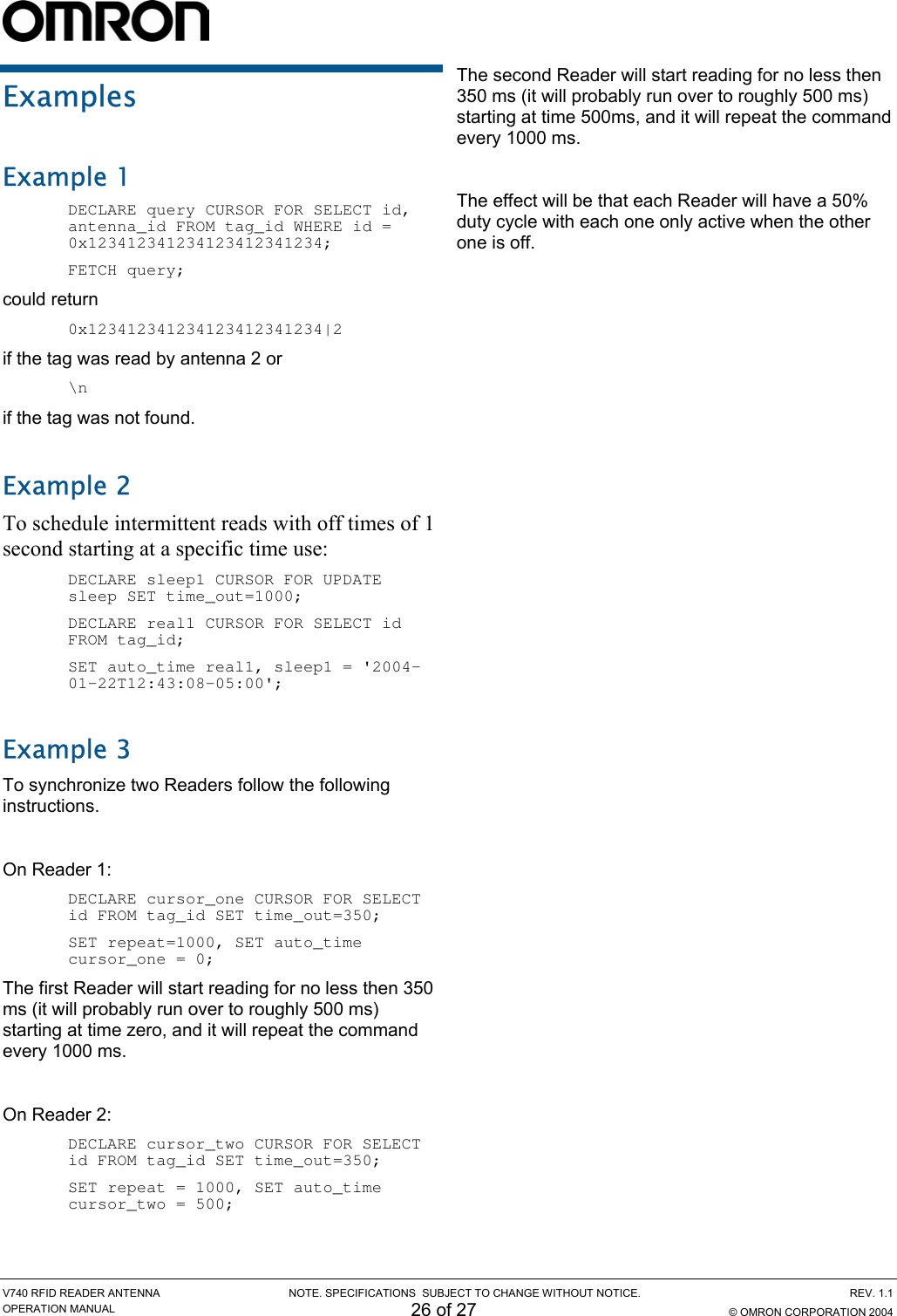
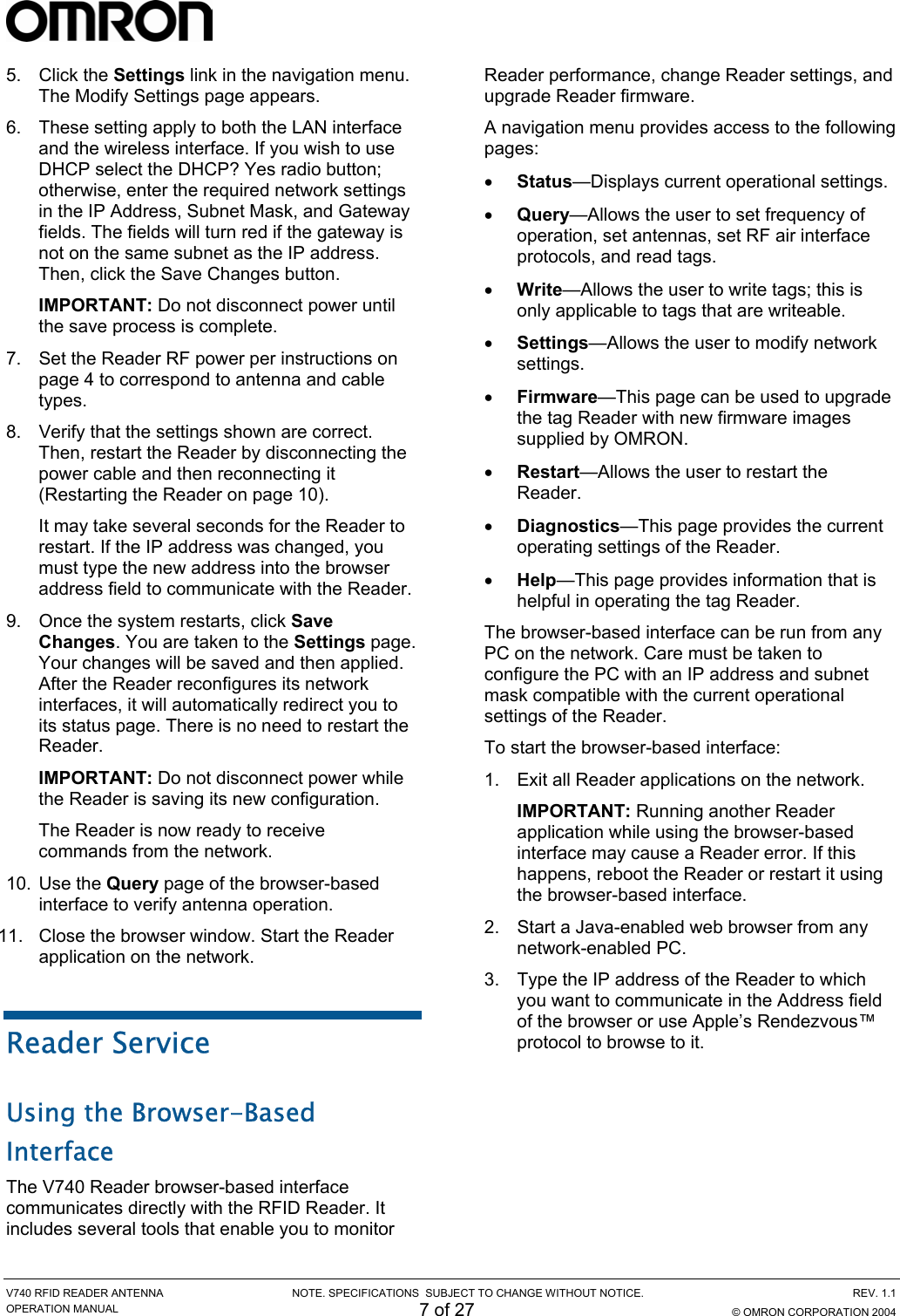
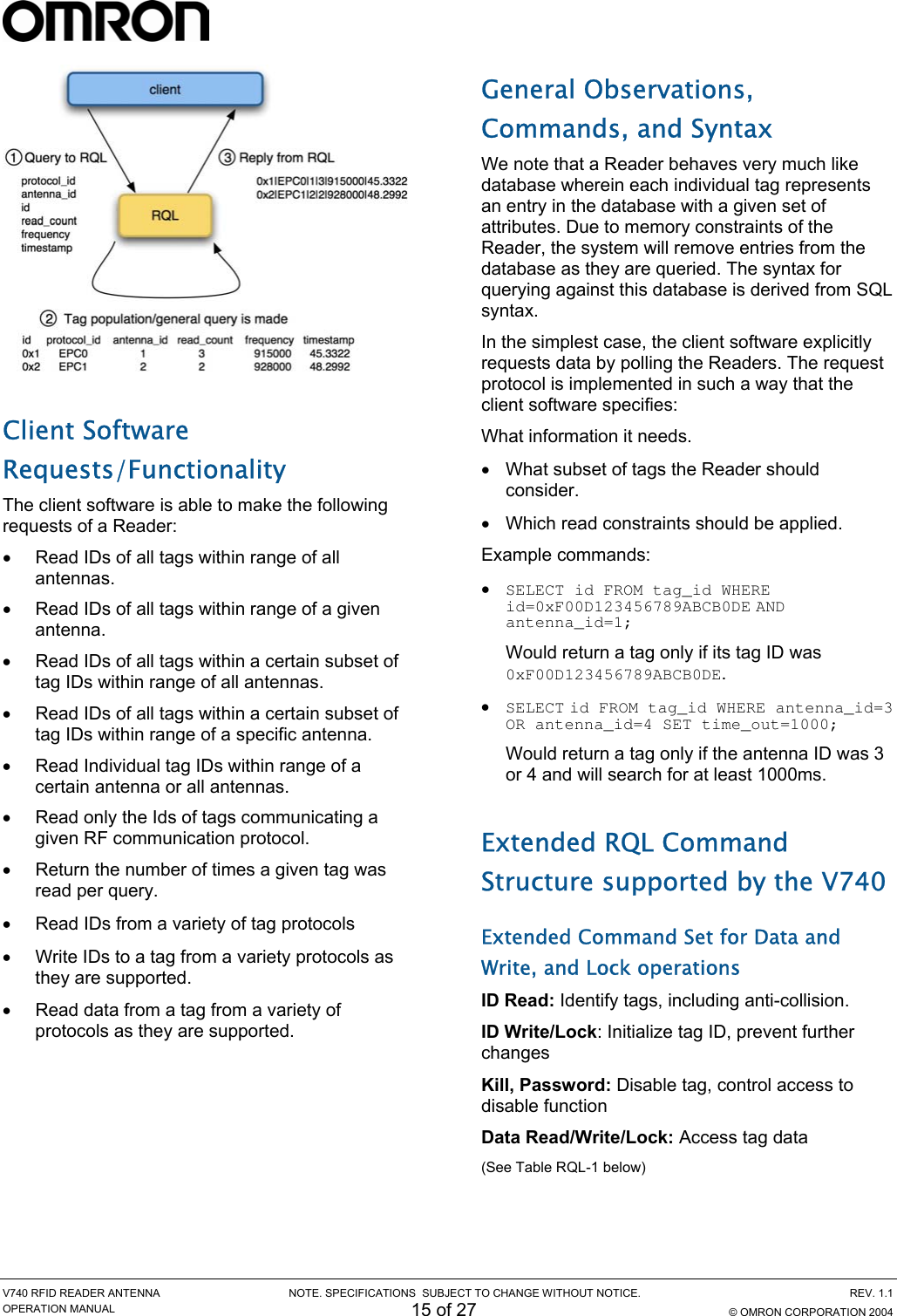
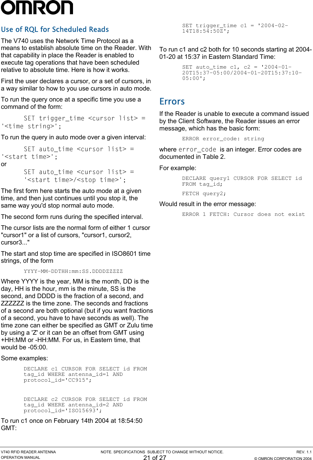
![V740 RFID READER NOTE. SPECIFICATIONS SUBJECT TO CHANGE WITHOUT NOTICE. REV. 1.1 OPERATION MANUAL 5 of 27 © OMRON CORPORATION 2004 Reader Installation The following parts are provided with the Reader: Part Qty. Part Number V740 RFID Reader 1 V740-BA50C**-US Power Supply 1 - Operation Manual 1 This manual IMPORTANT: Be sure the user reads the section on Declarations to maintain compliance with FCC regulations. Install the Reader You can place the Reader on a shelf or mount it to a wall. To mount the Reader on a wall: 1. Hold the Reader in its mounting location and mark the position of the mounting screws (2). Minimum screw size is #12 (M5). 2. Drill holes for the screws and install wall anchors if required. 3. Insert the screws and tighten until almost flush with the wall. 4. Slip the Reader over the screws and slide down to lock the screws in the keyhole openings. 5. Tighten the screws. Mechanical Loading - Mounting of the equipment in the rack should be such that a hazardous condition is not achieved due to uneven mechanical loading. Install the Antennas The antennas can be mounted directly to a variety of surfaces. Follow the installation instructions provided with the antennas. Connect the Reader A = RJ-45 Ethernet port C = RS232/RS485,GPIO(not available) B = Safe Mode button D = DC power input One to four dual-antennas can be connected to the Reader, depending on the number of cards installed. Silk-screen markings on the Reader identify the cards installed. 1. Connect required UHF antennas to the ports on the Reader (see “Antenna Connection Option” on page 6). IMPORTANT: Connect antennas to the ports before applying power to the Reader. Any port not having an antenna connected to it will be disabled when the Reader is powered on. 2. Verify that all antennas are securely connected. 3. Connect the Reader to the network by plugging an Ethernet cable into the Ethernet port. or Connect the Reader to a PC (personal computer) by plugging a crossover Ethernet cable into the Ethernet port. [If DHCP is to be used, then the network must be connected before powering up the Reader. If a DHCP server is not found the Reader will fall back to the IP address: “10.0.0.101”.] IMPORTANT: The Reader and the antennas are installed by only professionals at specific location and also they must be used at the separate distance of at least 21 cm (8.3in).MODULE A MODULE B FAULT / ERRORSTATUSACTIVITYMounting holes](https://usermanual.wiki/Omron-RFID-Business-Development-Department/V740-BA50CX2/User-Guide-511361-Page-5.png)
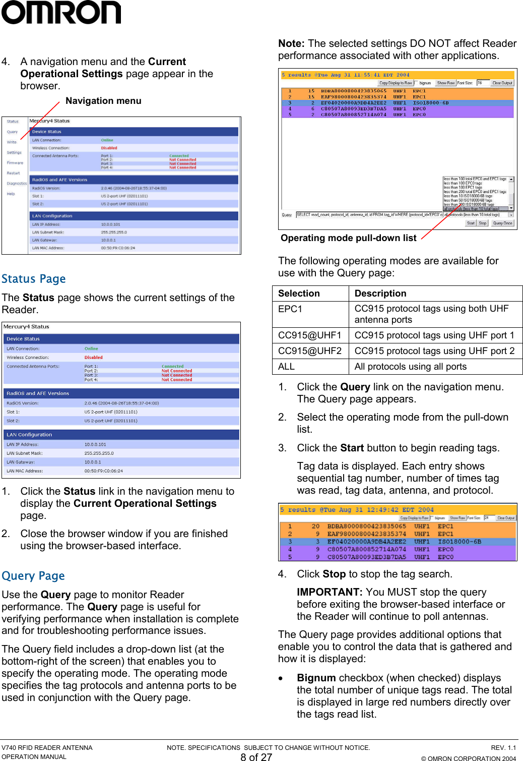
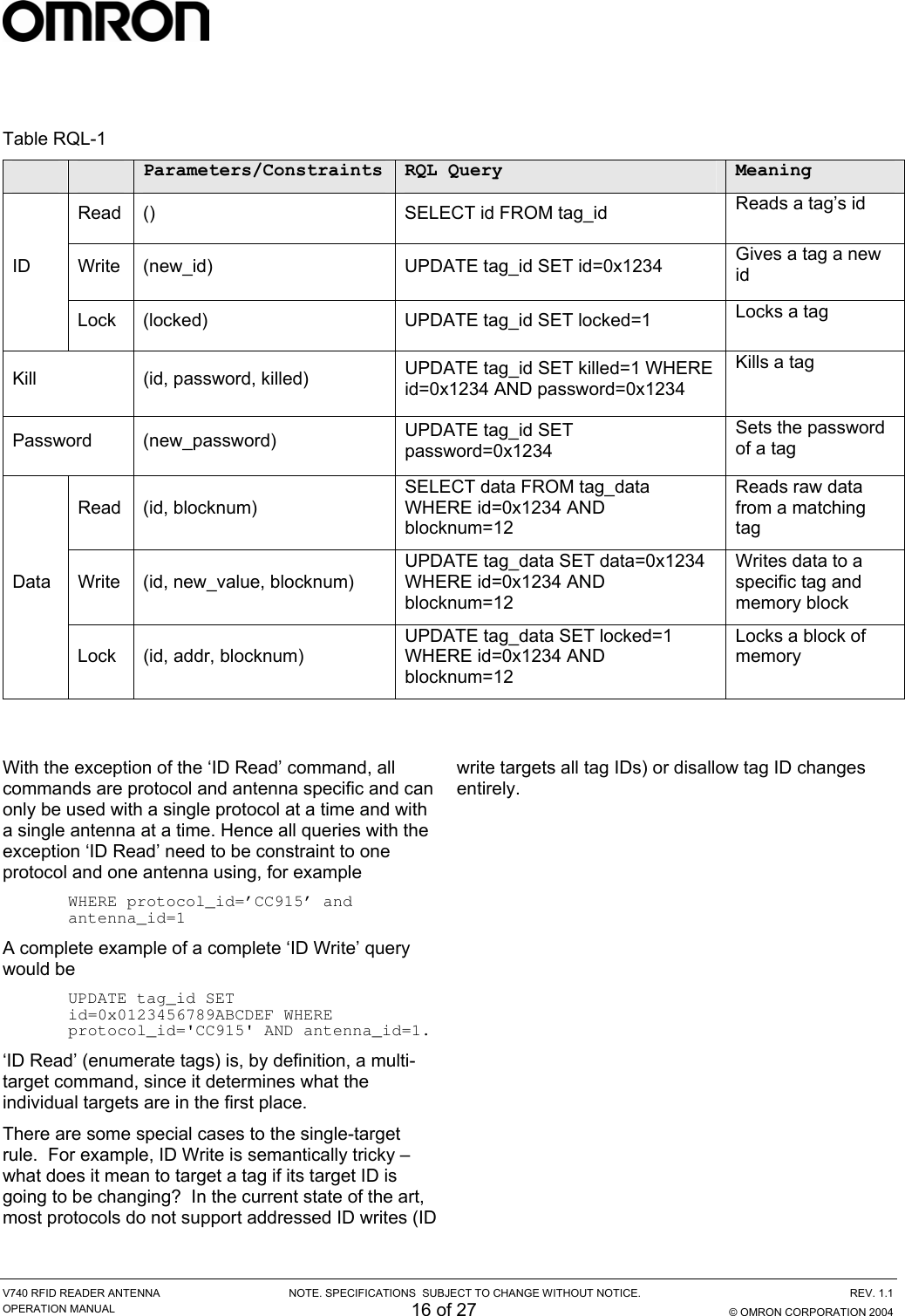
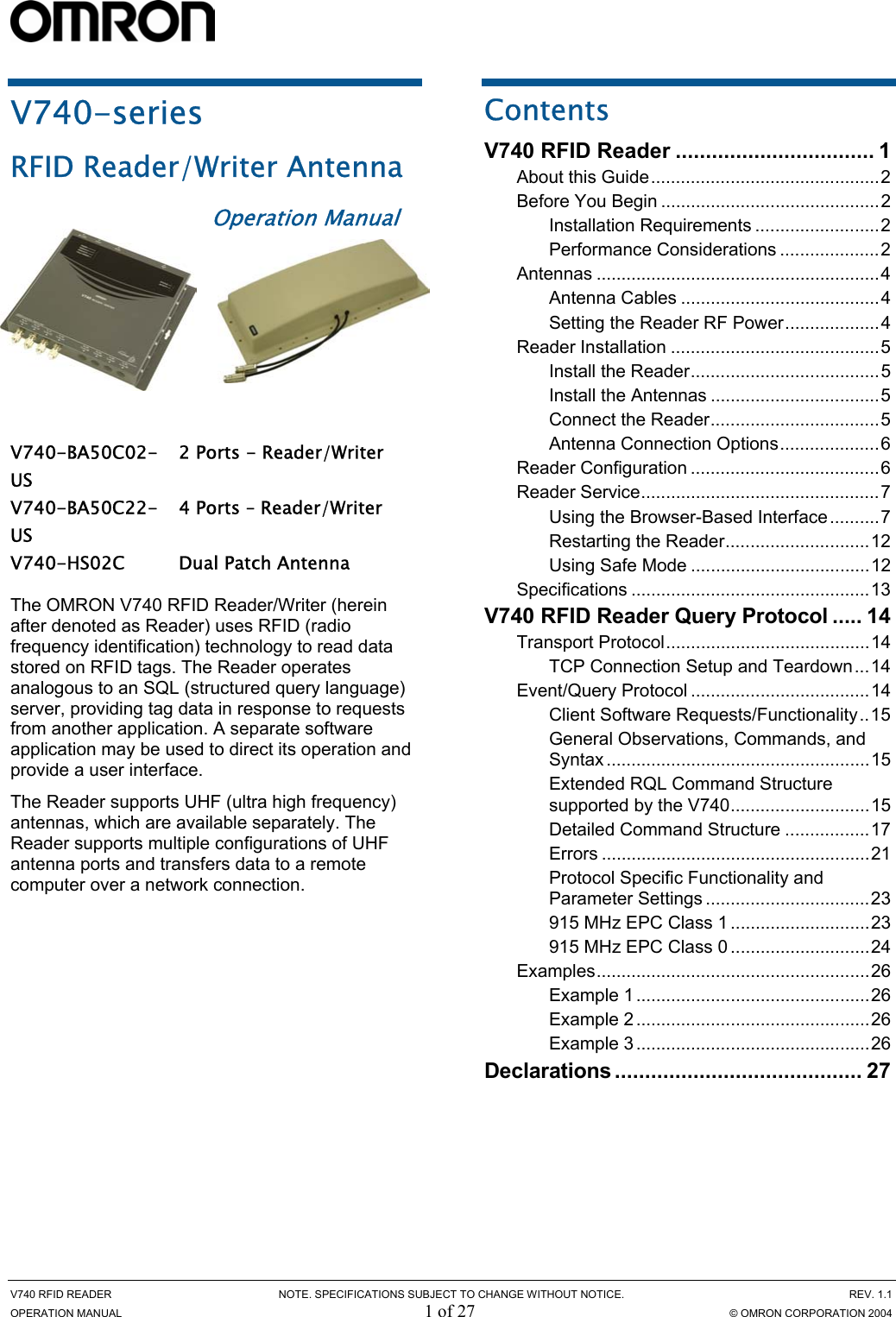
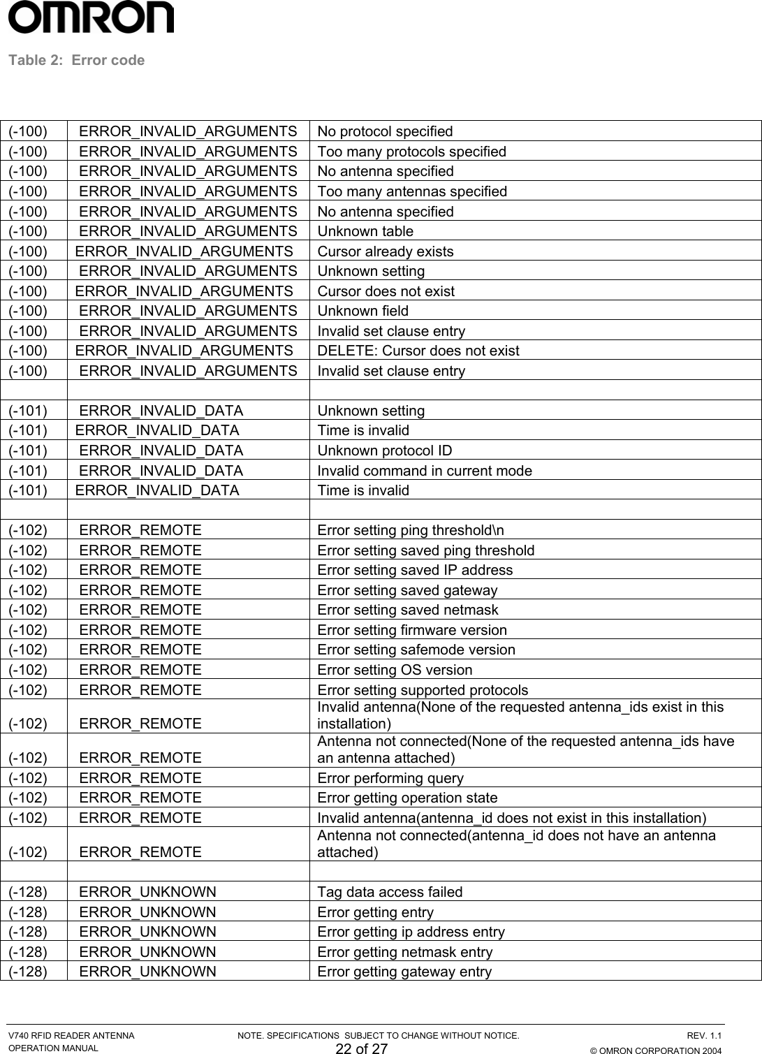
![V740 RFID READER ANTENNA NOTE. SPECIFICATIONS SUBJECT TO CHANGE WITHOUT NOTICE. REV. 1.1 OPERATION MANUAL 17 of 27 © OMRON CORPORATION 2004 RQL Table Schema As was mentioned before, RQL is derived from the SQL language, which allows the user to define arbitrary tables. RQL has predefined tables according to the schema below. NOTE: Tag_id and Tad_data values are case-sensitive and are all lowercase only. Read/Write Tag_id Type Read/Write Tag_data Type R protocol Int R id Hex String R antenna Int R/W blocknum Int R/W id Hex String R/W data Hex String W killed Int R locked Int W password Hex String R/W locked Int R frequency Int R dspmicros Int R timestamp string Read/Write Tag_id Type R version String R supported_protocols String Read/Write Settings Type R current_time String Detailed Command Structure Select, Where, Set The SELECT command is for querying the tag population of the Reader as well as static variables such as firmware version and supported protocols. The structure of a SELECT command is as follows: SELECT select_list FROM table_expression [where_specification] [set_specification]; A where_specification is entered as: WHERE boolean_expr boolean_expr can consist of any expression which evaluates to a boolean value. In many cases, this expression will be: expr binary_operator expr or unary_operator expr where binary_operator can be one of =, <, <=, >, >= , <>, AND, or OR, and unary_operator can be “NOT”. Parentheses may also be used to create associations of subexpressions. In the presence of a WHERE clause, SELECT will not return any rows for which the WHERE condition does not evaluate to TRUE. A set_specification is entered as: SET expression In the following we provide some more examples for the usage of SELECT, WHERE, SET: • To query a specific tag, given its ePC code, one can specify a specific tag with id as a hexadecimal number: SELECT id FROM tag_id WHERE id=id AND antenna_id=antenna_id; SELECT id FROM tag_id WHERE id=id SET time_out=500; The Reader returns the tag if the tag is present followed by an empty event (‘\n’) or an empty](https://usermanual.wiki/Omron-RFID-Business-Development-Department/V740-BA50CX2/User-Guide-511361-Page-17.png)
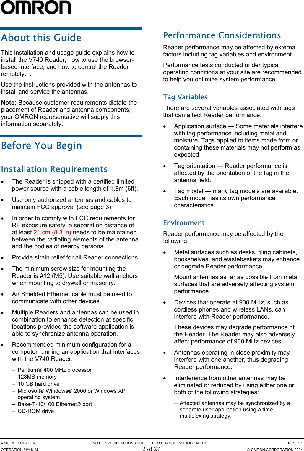
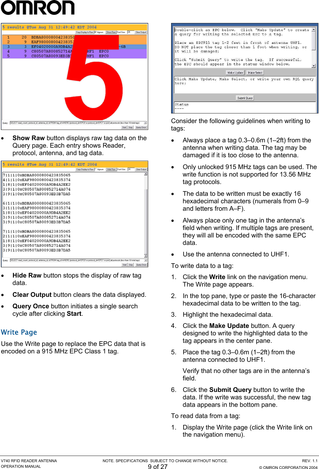
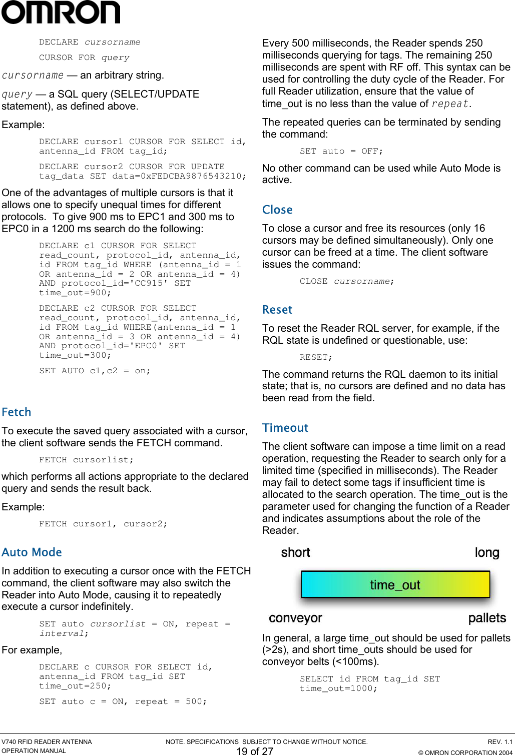
![V740 RFID READER ANTENNA NOTE. SPECIFICATIONS SUBJECT TO CHANGE WITHOUT NOTICE. REV. 1.1 OPERATION MANUAL 18 of 27 © OMRON CORPORATION 2004 event (‘\n’) if tags matching the WHERE clause are not present. The first version requests a read from a specific antenna, while the second does not. The second command imposes a time out constraint of 500ms; i.e., the Reader stops reading and returns all collected data after 500ms. The order in which specifying arguments are used is irrelevant. The default timeout if none is specified is 250ms. Any previous statement’s use of the time_out variable will change the default timeout until a RESET is asserted. It is important to always use a timeout in specifying a query to achieve optimal performance for a given application. This will be discussed later in section • To query a specific sub class of tags, given a range of ePCs: SELECT id FROM tag_id WHERE tag_id>min_tag_id AND tag_id<max_tag_id SET timeout=1000; The Reader returns the ePCs for all the present tags between id_min and id_max, which are hexadecimal values. • To query all tags: SELECT id FROM tag_id SET timeout=2500; SELECT id FROM tag_id WHERE antenna_id=1 SET timeout=2500; The Reader returns all the tags it can find. The second version requests a read from a specific antenna, while the first does not. • The client software specifies which information it requires in the select_list field of the SELECT command: SELECT id, antenna_id FROM tag_id SET timeout=2500; SELECT frequency, timestamp, id, antenna_id FROM tag_id SET time_out=1000; Returns the id and antenna_id of every tag in the field in the first example and the frequency and time the tag was read at (seconds from the unix epoch, Jan 1, 1970) in the second example. Update, Where The UPDATE command is to write new data into a table. This can be used to write a new tag_id or sleep the Reader for a specified amount of time. The structure of an UPDATE command is as follows: UPDATE table SET col=expression [, …] [WHERE wherelist]; table and col entries are provided in Table 1. The WHERE clause is specified in the same manner as in the SELECT call above. In the following we provide some examples for usage of UPDATE: • To write data for a 64-bit ePC tag id with a specified lock code, password and block_number: UPDATE tag_data SET data=0xFEDCBA9876543210, block_number=0, lock_code=0xef, password=0xcd WHERE protocol=’CC915’ AND antenna_id=1; The Reader returns the tag_id if the write operation was successful or “Error 128: Error encountered while attempting to process tags\n\n” in safe mode, and "Error 128: Error encountered while attempting to process tags\n\n" in single query mode otherwise. • To write for a specified amount of time: UPDATE tag_data SET data=0xFEDCBA9876543210, block_number=1, lock_code=0xef, password=0xcd, time_out=250 WHERE protocol=’CC915’ AND antenna_id=1; Would try to write the tag id for 250ms. • To sleep the Reader for a specified amount of time: UPDATE sleep SET time_out=500; Would turn off the RF interface for 500ms. This can be useful for scheduling Readers and reducing interference. • Other Updates: kill, locking, password UPDATE tag_id SET killed=1, id=0x112233445566778899AABBCC,password=0x88 WHERE protocol_id='EPC1' AND antenna_id=4; UPDATE tag_id SET locked=1, id=0x0123456789ABCDEF WHERE protocol_id='EPC1' AND antenna_id=4; UPDATE tag_id SET password=0x88, id=0x0123456789ABCDEF WHERE protocol_id='EPC1' AND antenna_id=4; Cursors The client software has the ability to declare cursors (saved queries), which it can then use to request data repeatedly using the OPEN or the AUTO_MODE command. A maximum of 16 cursors can be defined. To create a cursor:](https://usermanual.wiki/Omron-RFID-Business-Development-Department/V740-BA50CX2/User-Guide-511361-Page-18.png)
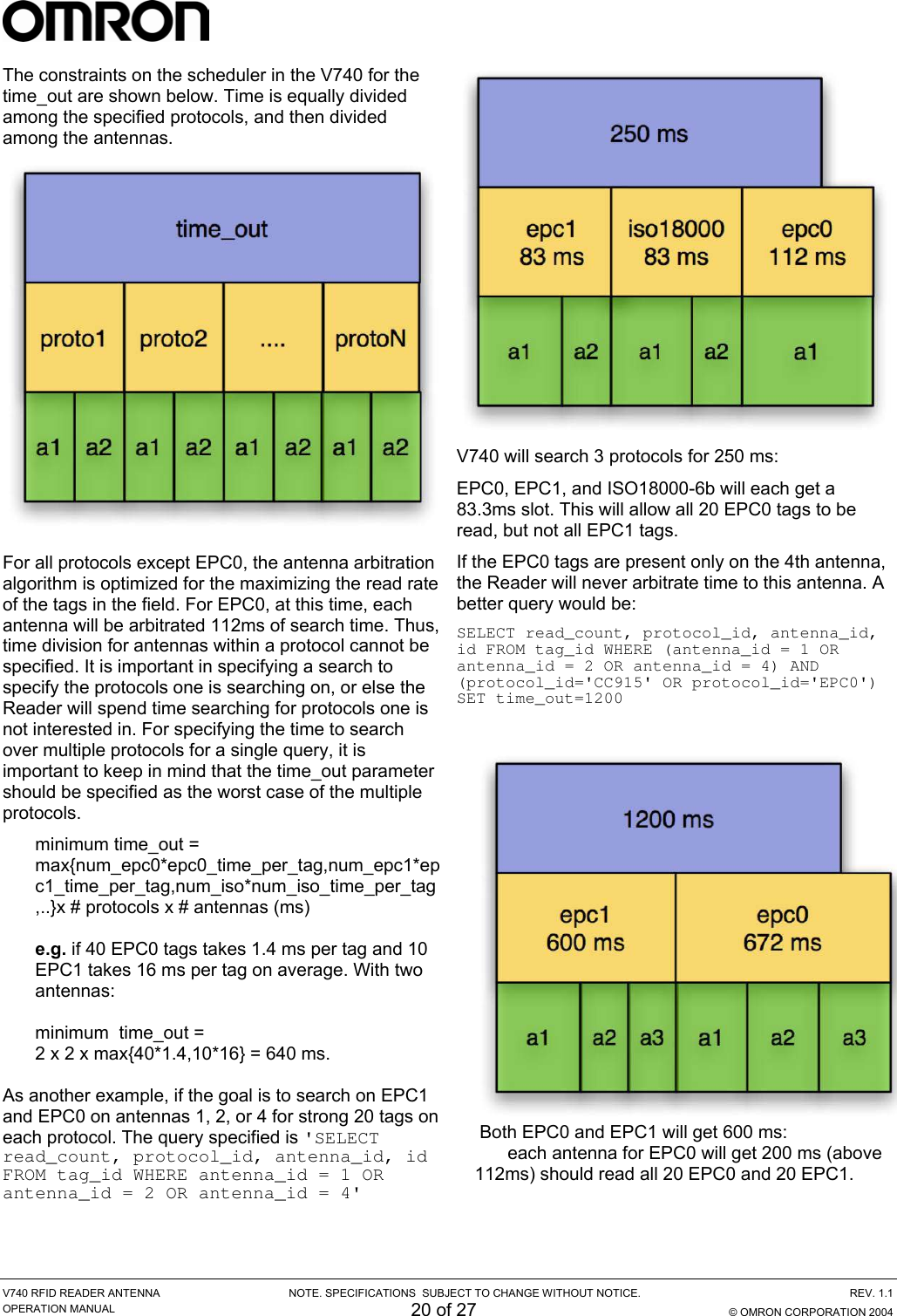
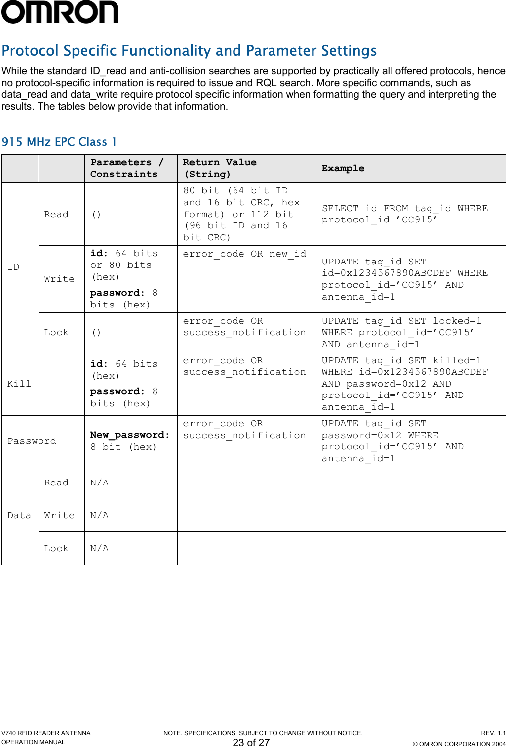

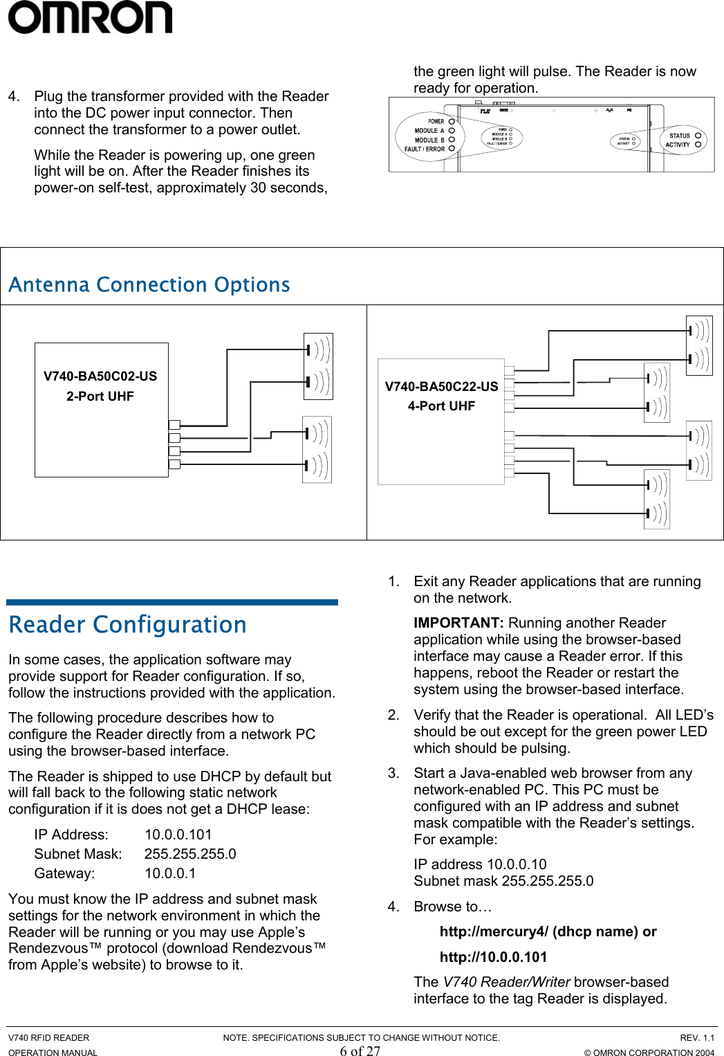
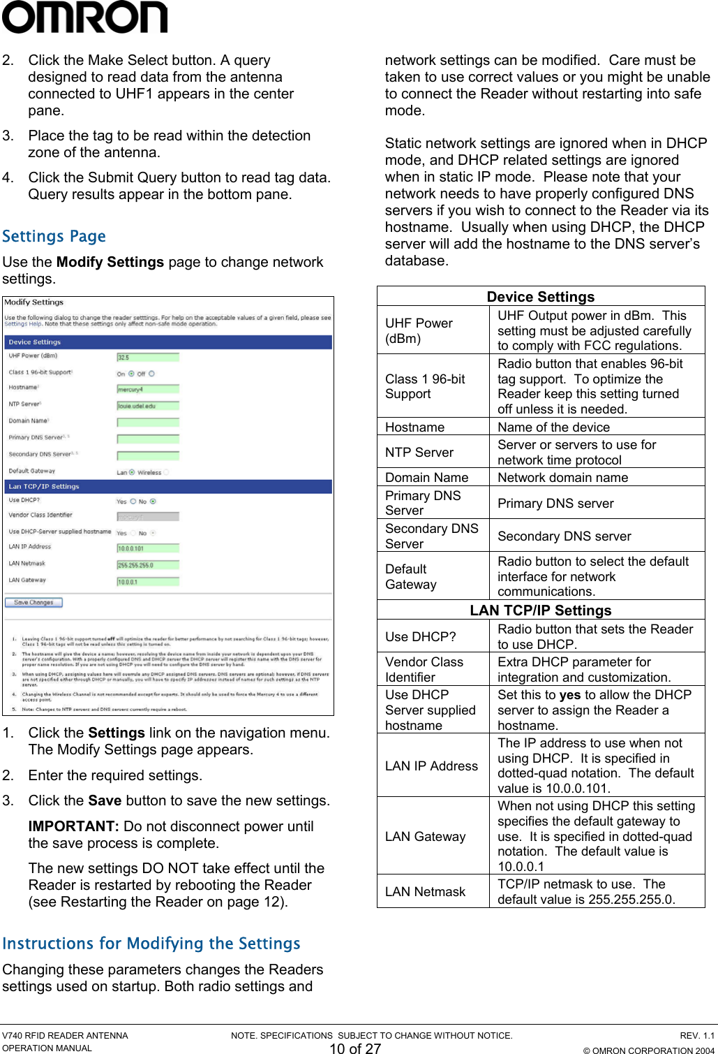
![V740 RFID READER ANTENNA NOTE. SPECIFICATIONS SUBJECT TO CHANGE WITHOUT NOTICE. REV. 1.1 OPERATION MANUAL 25 of 27 © OMRON CORPORATION 2004 915 MHz ISO18000-6B Parameters / Constraints Return Value (String) Example Read () 80 bit (64 bit ID and 16 bit CRC, hex) SELECT id FROM tag_id WHERE protocol_id=’ISO18000-6B’ ID Write N/A Lock N/A Kill N/A Password N/A Read id: 64 bit (hex) addr: integer [0…223] 8 bit (hex) SELECT data FROM tag_data WHERE id=0x1234567890ABCDEF AND blocknum=12 AND protocol_id=’ISO18000-6B’ AND antenna_id=1 Data Write id: 64 bit (hex) addr: integer [8…223] new_value: 8 bit (hex) error_code OR success_notification UPDATE tag_data SET data=0x12 WHERE id=0x1234567890ABCDEF AND blocknum=12 AND protocol_id=’ISO18000-6B’ AND antenna_id=1 Lock id: 64 bit (hex) addr: integer [8…223] error_code OR success_notification UPDATE tag_data SET locked=1 WHERE id=0x1234567890ABCDEF AND blocknum=12 AND protocol_id=’ISO18000-6B’ AND antenna_id=1](https://usermanual.wiki/Omron-RFID-Business-Development-Department/V740-BA50CX2/User-Guide-511361-Page-25.png)