Omron RFID Business Development Department V740-BA50CX2 RFID Frequency Hopping Transmitter User Manual 511361
Omron Corporation, RFID Business Development Depar RFID Frequency Hopping Transmitter 511361
users manual

V740 RFID READER NOTE. SPECIFICATIONS SUBJECT TO CHANGE WITHOUT NOTICE. REV. 1.1
OPERATION MANUAL 1 of 27 © OMRON CORPORATION 2004
V740-series
RFID Reader/Writer Antenna
Operation Manual
V740-BA50C02-
US
2 Ports - Reader/Writer
V740-BA50C22-
US
4 Ports – Reader/Writer
V740-HS02C Dual Patch Antenna
The OMRON V740 RFID Reader/Writer (herein
after denoted as Reader) uses RFID (radio
frequency identification) technology to read data
stored on RFID tags. The Reader operates
analogous to an SQL (structured query language)
server, providing tag data in response to requests
from another application. A separate software
application may be used to direct its operation and
provide a user interface.
The Reader supports UHF (ultra high frequency)
antennas, which are available separately. The
Reader supports multiple configurations of UHF
antenna ports and transfers data to a remote
computer over a network connection.
Contents
V740 RFID Reader ................................. 1
About this Guide..............................................2
Before You Begin ............................................2
Installation Requirements .........................2
Performance Considerations ....................2
Antennas .........................................................4
Antenna Cables ........................................4
Setting the Reader RF Power...................4
Reader Installation ..........................................5
Install the Reader......................................5
Install the Antennas ..................................5
Connect the Reader..................................5
Antenna Connection Options....................6
Reader Configuration ......................................6
Reader Service................................................7
Using the Browser-Based Interface..........7
Restarting the Reader.............................12
Using Safe Mode ....................................12
Specifications ................................................13
V740 RFID Reader Query Protocol ..... 14
Transport Protocol.........................................14
TCP Connection Setup and Teardown...14
Event/Query Protocol ....................................14
Client Software Requests/Functionality..15
General Observations, Commands, and
Syntax .....................................................15
Extended RQL Command Structure
supported by the V740............................15
Detailed Command Structure .................17
Errors ......................................................21
Protocol Specific Functionality and
Parameter Settings .................................23
915 MHz EPC Class 1 ............................23
915 MHz EPC Class 0 ............................24
Examples.......................................................26
Example 1 ...............................................26
Example 2 ...............................................26
Example 3 ...............................................26
Declarations ......................................... 27

V740 RFID READER NOTE. SPECIFICATIONS SUBJECT TO CHANGE WITHOUT NOTICE. REV. 1.1
OPERATION MANUAL 2 of 27 © OMRON CORPORATION 2004
About this Guide
This installation and usage guide explains how to
install the V740 Reader, how to use the browser-
based interface, and how to control the Reader
remotely. .
Use the instructions provided with the antennas to
install and service the antennas.
Note: Because customer requirements dictate the
placement of Reader and antenna components,
your OMRON representative will supply this
information separately.
Before You Begin
Installation Requirements
• The Reader is shipped with a certified limited
power source with a cable length of 1.8m (6ft).
• Use only authorized antennas and cables to
maintain FCC approval (see page 3).
• In order to comply with FCC requirements for
RF exposure safety, a separation distance of
at least 21 cm (8.3 in) needs to be maintained
between the radiating elements of the antenna
and the bodies of nearby persons.
• Provide strain relief for all Reader connections.
• The minimum screw size for mounting the
Reader is #12 (M5). Use suitable wall anchors
when mounting to drywall or masonry.
• An Shielded Ethernet cable must be used to
communicate with other devices.
• Multiple Readers and antennas can be used in
combination to enhance detection at specific
locations provided the software application is
able to synchronize antenna operation.
• Recommended minimum configuration for a
computer running an application that interfaces
with the V740 Reader:
– Pentium® 400 MHz processor
– 128MB memory
– 10 GB hard drive
– Microsoft® Windows® 2000 or Windows XP
operating system
– Base-T-10/100 Ethernet® port
– CD-ROM drive
Performance Considerations
Reader performance may be affected by external
factors including tag variables and environment.
Performance tests conducted under typical
operating conditions at your site are recommended
to help you optimize system performance.
Tag Variables
There are several variables associated with tags
that can affect Reader performance:
• Application surface — Some materials interfere
with tag performance including metal and
moisture. Tags applied to items made from or
containing these materials may not perform as
expected.
• Tag orientation — Reader performance is
affected by the orientation of the tag in the
antenna field.
• Tag model — many tag models are available.
Each model has its own performance
characteristics.
Environment
Reader performance may be affected by the
following:
• Metal surfaces such as desks, filing cabinets,
bookshelves, and wastebaskets may enhance
or degrade Reader performance.
Mount antennas as far as possible from metal
surfaces that are adversely affecting system
performance.
• Devices that operate at 900 MHz, such as
cordless phones and wireless LANs, can
interfere with Reader performance.
These devices may degrade performance of
the Reader. The Reader may also adversely
affect performance of 900 MHz devices.
• Antennas operating in close proximity may
interfere with one another, thus degrading
Reader performance.
• Interference from other antennas may be
eliminated or reduced by using either one or
both of the following strategies:
– Affected antennas may be synchronized by a
separate user application using a time-
multiplexing strategy.

V740 RFID READER NOTE. SPECIFICATIONS SUBJECT TO CHANGE WITHOUT NOTICE. REV. 1.1
OPERATION MANUAL 3 of 27 © OMRON CORPORATION 2004
– Antenna power can be reduced by reconfiguring
the RF Transmit Power setting for the Reader.
V740 RFID READER NOTE. SPECIFICATIONS SUBJECT TO CHANGE WITHOUT NOTICE. REV. 1.1
OPERATION MANUAL 4 of 27 © OMRON CORPORATION 2004
Authorized Antennas
The only antennas authorized by the FCC for use
with the V740 Reader/Writer are listed below.
Detailed information on each antenna is available
from their respective manufacturers.
IMPORTANT: No other antennas may be used
with the V740 Reader/Writer without violating FCC
regulations. It is the responsibility of the user to
comply with this requirement.
OMRON Dual Patch Antenna
Model: V740-HS02C
Gain: 6 dBi max.
Connector: Reverse TNC
Antenna Cables
The only cables authorized by the FCC for use with
the V740 Reader/Writerare listed below:
Short R-TNC/N
Model: V740-A01-3.0M
Length: 9.8'
Insertion Loss: 1.4 dB min.
Cable Type: 3D-2V
Connectors: Reverse TNC to Type N
Long R-TNC/N
Model: V740-A01-10M
Length: 32.8'
Insertion Loss: 1.5 dB min.
Cable Type: 5D-SFA
Connectors: Reverse TNC to Type N
Setting the Reader RF Power
During initial installation, the Reader must be
properly configured to use the correct RF power to
comply with FCC regulations. DO NOT increase
the power beyond this level.
The maximum RF power is determined from
antenna gain and antenna cable loss using the
formula:
Pmax = 36 dBm - Antenna Gain + Cable Loss
For example, if the antenna has a maximum gain
of 6 dBi, and the cable has a minimum loss of 1.4
dB, the maximum RF power that may be set is (36-
6 + 1.4) = 31.4 dBm.
The Reader RF Power is set through the Settings
Page as described on Page 10. Note that in no
case may the power be set higher than 32.5 dBm.
Recommended Power Settings
Antenna Type Short Cable Long Cable
V740-HS02C 31.4 dBm 31.5dBm
V740 RFID READER NOTE. SPECIFICATIONS SUBJECT TO CHANGE WITHOUT NOTICE. REV. 1.1
OPERATION MANUAL 5 of 27 © OMRON CORPORATION 2004
Reader Installation
The following parts are provided with the Reader:
Part Qty. Part Number
V740 RFID Reader 1 V740-BA50C**-US
Power Supply 1 -
Operation Manual 1 This manual
IMPORTANT: Be sure the user reads the section
on Declarations to maintain compliance with FCC
regulations.
Install the Reader
You can place the Reader on a shelf or mount it to
a wall.
To mount the Reader on a wall:
1. Hold the Reader in its mounting location and
mark the position of the mounting screws (2).
Minimum screw size is #12 (M5).
2. Drill holes for the screws and install wall
anchors if required.
3. Insert the screws and tighten until almost flush
with the wall.
4. Slip the Reader over the screws and slide
down to lock the screws in the keyhole
openings.
5. Tighten the screws.
Mechanical Loading - Mounting of the equipment
in the rack should be such that a hazardous
condition is not achieved due to uneven
mechanical loading.
Install the Antennas
The antennas can be mounted directly to a variety
of surfaces. Follow the installation instructions
provided with the antennas.
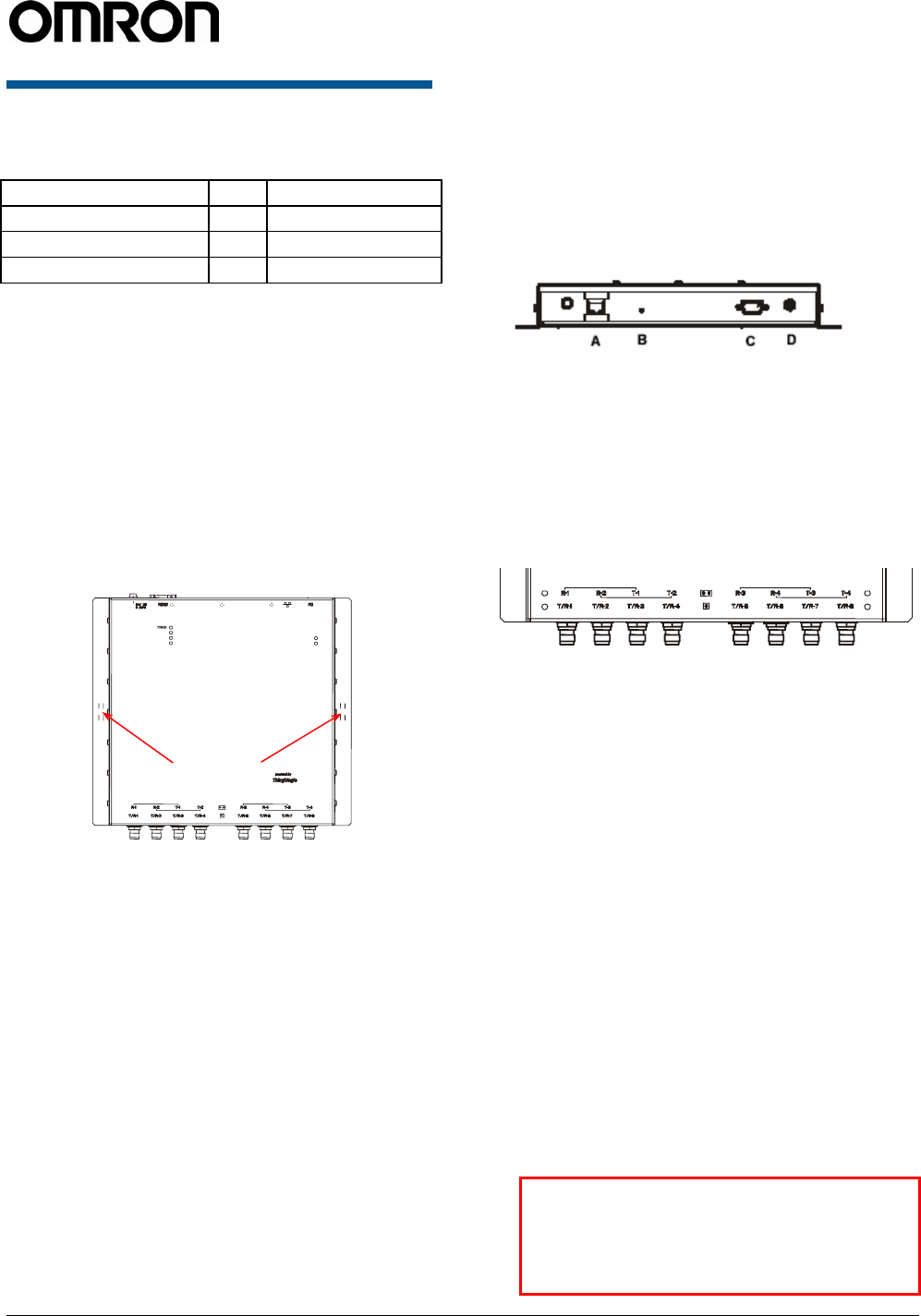
Connect the Reader
A = RJ-45 Ethernet port C =
RS232/RS485,GPIO
(not
available)
B = Safe Mode button D = DC power input
One to four dual-antennas can be connected to the
Reader, depending on the number of cards
installed. Silk-screen markings on the Reader
identify the cards installed.
1. Connect required UHF antennas to the ports
on the Reader (see “Antenna Connection
Option” on page 6).
IMPORTANT: Connect antennas to the ports
before applying power to the Reader. Any port
not having an antenna connected to it will be
disabled when the Reader is powered on.
2. Verify that all antennas are securely
connected.
3. Connect the Reader to the network by plugging
an Ethernet cable into the Ethernet port.
or
Connect the Reader to a PC (personal
computer) by plugging a crossover Ethernet
cable into the Ethernet port.
[If DHCP is to be used, then the network must
be connected before powering up the Reader.
If a DHCP server is not found the Reader will
fall back to the IP address: “10.0.0.101”.]
IMPORTANT: The Reader and the antennas
are installed by only professionals at
specific location and also they must be
used at the separate distance of at least 21
cm (8.3in).
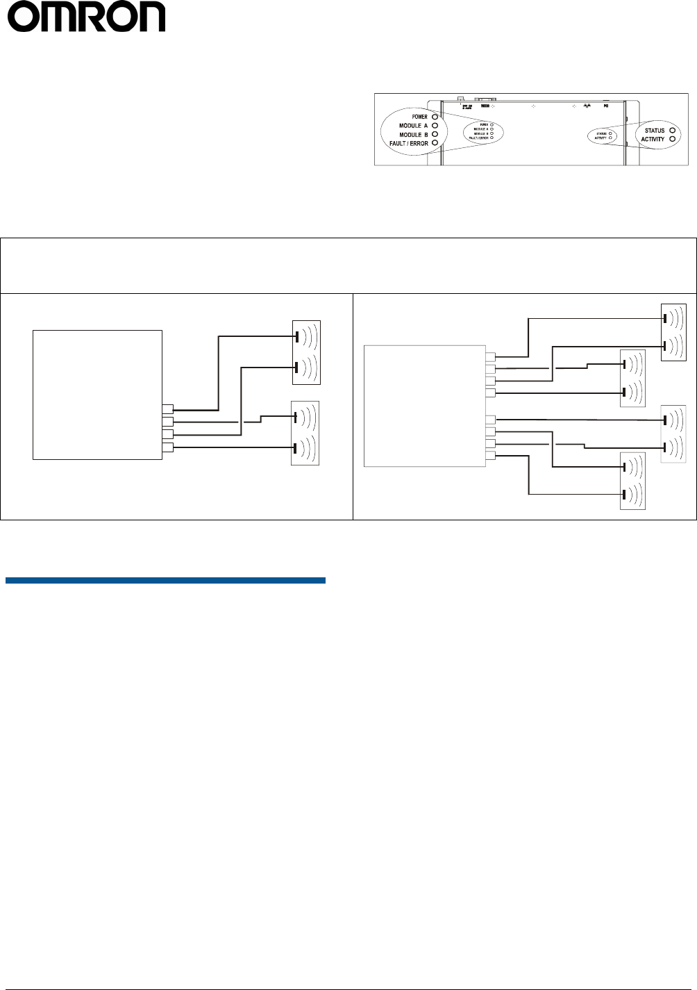
MODULE A
MODULE B
FAULT / ERROR
STATUS
ACTIVITY
Mounting
holes
V740 RFID READER NOTE. SPECIFICATIONS SUBJECT TO CHANGE WITHOUT NOTICE. REV. 1.1
OPERATION MANUAL 6 of 27 © OMRON CORPORATION 2004
4. Plug the transformer provided with the Reader
into the DC power input connector. Then
connect the transformer to a power outlet.
While the Reader is powering up, one green
light will be on. After the Reader finishes its
power-on self-test, approximately 30 seconds,
the green light will pulse. The Reader is now
ready for operation.
Antenna Connection Options
Reader Configuration
In some cases, the application software may
provide support for Reader configuration. If so,
follow the instructions provided with the application.
The following procedure describes how to
configure the Reader directly from a network PC
using the browser-based interface.
The Reader is shipped to use DHCP by default but
will fall back to the following static network
configuration if it is does not get a DHCP lease:
IP Address: 10.0.0.101
Subnet Mask: 255.255.255.0
Gateway: 10.0.0.1
You must know the IP address and subnet mask
settings for the network environment in which the
Reader will be running or you may use Apple’s
Rendezvous™ protocol (download Rendezvous™
from Apple’s website) to browse to it.
1. Exit any Reader applications that are running
on the network.
IMPORTANT: Running another Reader
application while using the browser-based
interface may cause a Reader error. If this
happens, reboot the Reader or restart the
system using the browser-based interface.
2. Verify that the Reader is operational. All LED’s
should be out except for the green power LED
which should be pulsing.
3. Start a Java-enabled web browser from any
network-enabled PC. This PC must be
configured with an IP address and subnet
mask compatible with the Reader’s settings.
For example:
IP address 10.0.0.10
Subnet mask 255.255.255.0
4. Browse to…
http://mercury4/ (dhcp name) or
http://10.0.0.101
The V740 Reader/Writer browser-based
interface to the tag Reader is displayed.
V
740-BA50C02-US
2-Port UHF
V
740-BA50C22-US
4-Port UHF

V740 RFID READER ANTENNA NOTE. SPECIFICATIONS SUBJECT TO CHANGE WITHOUT NOTICE. REV. 1.1
OPERATION MANUAL 7 of 27 © OMRON CORPORATION 2004
5. Click the Settings link in the navigation menu.
The Modify Settings page appears.
6. These setting apply to both the LAN interface
and the wireless interface. If you wish to use
DHCP select the DHCP? Yes radio button;
otherwise, enter the required network settings
in the IP Address, Subnet Mask, and Gateway
fields. The fields will turn red if the gateway is
not on the same subnet as the IP address.
Then, click the Save Changes button.
IMPORTANT: Do not disconnect power until
the save process is complete.
7. Set the Reader RF power per instructions on
page 4 to correspond to antenna and cable
types.
8. Verify that the settings shown are correct.
Then, restart the Reader by disconnecting the
power cable and then reconnecting it
(Restarting the Reader on page 10).
It may take several seconds for the Reader to
restart. If the IP address was changed, you
must type the new address into the browser
address field to communicate with the Reader.
9. Once the system restarts, click Save
Changes. You are taken to the Settings page.
Your changes will be saved and then applied.
After the Reader reconfigures its network
interfaces, it will automatically redirect you to
its status page. There is no need to restart the
Reader.
IMPORTANT: Do not disconnect power while
the Reader is saving its new configuration.
The Reader is now ready to receive
commands from the network.
10. Use the Query page of the browser-based
interface to verify antenna operation.
11. Close the browser window. Start the Reader
application on the network.
Reader Service
Using the Browser-Based
Interface
The V740 Reader browser-based interface
communicates directly with the RFID Reader. It
includes several tools that enable you to monitor
Reader performance, change Reader settings, and
upgrade Reader firmware.
A navigation menu provides access to the following
pages:
• Status—Displays current operational settings.
• Query—Allows the user to set frequency of
operation, set antennas, set RF air interface
protocols, and read tags.
• Write—Allows the user to write tags; this is
only applicable to tags that are writeable.
• Settings—Allows the user to modify network
settings.
• Firmware—This page can be used to upgrade
the tag Reader with new firmware images
supplied by OMRON.
• Restart—Allows the user to restart the
Reader.
• Diagnostics—This page provides the current
operating settings of the Reader.
• Help—This page provides information that is
helpful in operating the tag Reader.
The browser-based interface can be run from any
PC on the network. Care must be taken to
configure the PC with an IP address and subnet
mask compatible with the current operational
settings of the Reader.
To start the browser-based interface:
1. Exit all Reader applications on the network.
IMPORTANT: Running another Reader
application while using the browser-based
interface may cause a Reader error. If this
happens, reboot the Reader or restart it using
the browser-based interface.
2. Start a Java-enabled web browser from any
network-enabled PC.
3. Type the IP address of the Reader to which
you want to communicate in the Address field
of the browser or use Apple’s Rendezvous™
protocol to browse to it.
V740 RFID READER ANTENNA NOTE. SPECIFICATIONS SUBJECT TO CHANGE WITHOUT NOTICE. REV. 1.1
OPERATION MANUAL 8 of 27 © OMRON CORPORATION 2004
4. A navigation menu and the Current
Operational Settings page appear in the
browser.
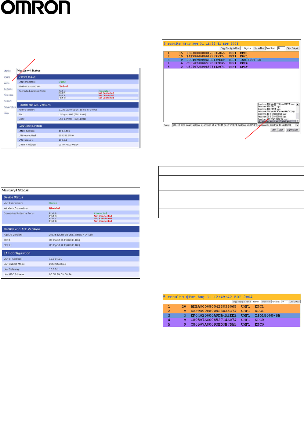
Status Page
The Status page shows the current settings of the
Reader.
1. Click the Status link in the navigation menu to
display the Current Operational Settings
page.
2. Close the browser window if you are finished
using the browser-based interface.
Query Page
Use the Query page to monitor Reader
performance. The Query page is useful for
verifying performance when installation is complete
and for troubleshooting performance issues.
The Query field includes a drop-down list (at the
bottom-right of the screen) that enables you to
specify the operating mode. The operating mode
specifies the tag protocols and antenna ports to be
used in conjunction with the Query page.
Note: The selected settings DO NOT affect Reader
performance associated with other applications.
The following operating modes are available for
use with the Query page:
Selection Description
EPC1 CC915 protocol tags using both UHF
antenna ports
CC915@UHF1 CC915 protocol tags using UHF port 1
CC915@UHF2 CC915 protocol tags using UHF port 2
ALL All protocols using all ports
1. Click the Query link on the navigation menu.
The Query page appears.
2. Select the operating mode from the pull-down
list.
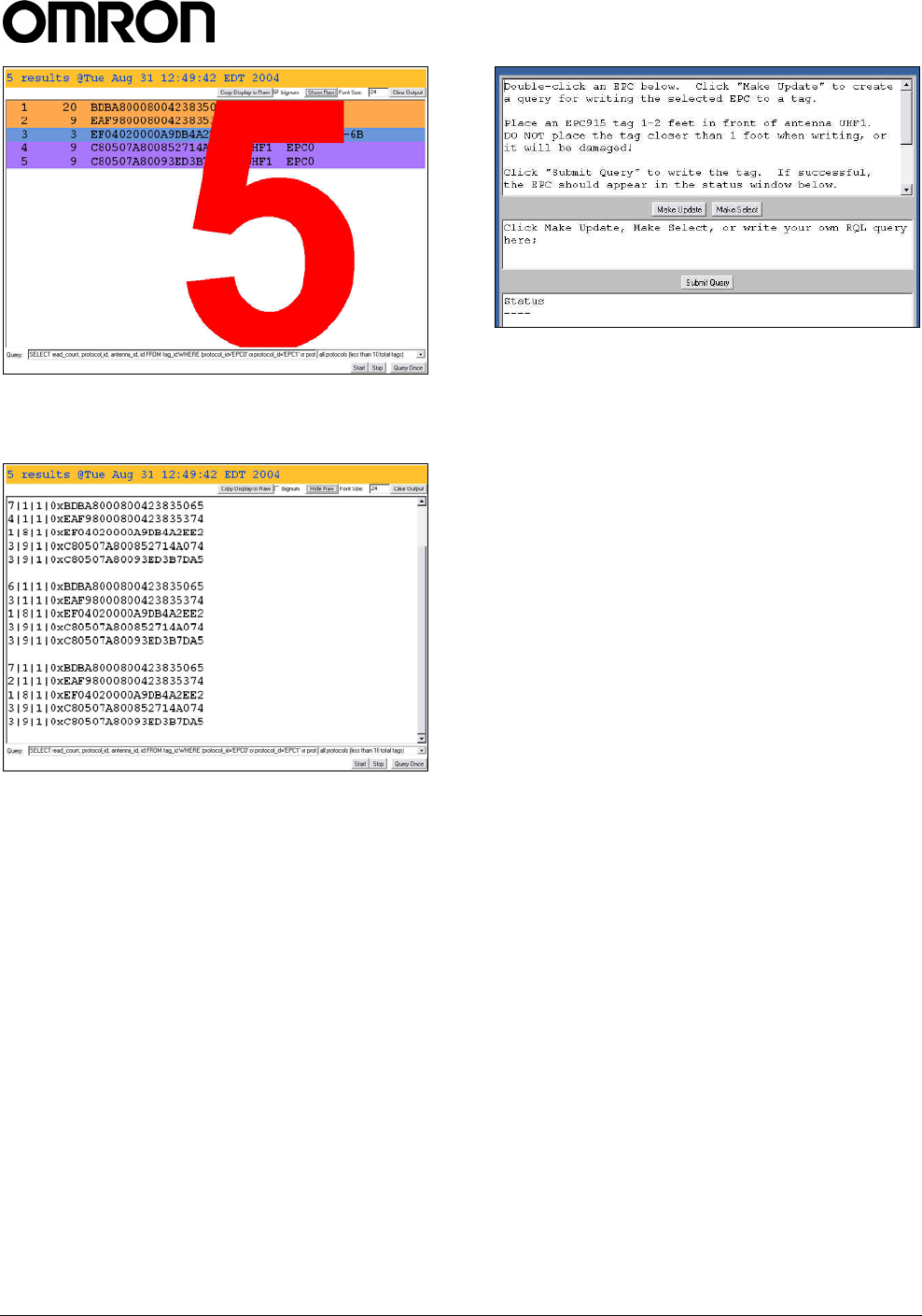
3. Click the Start button to begin reading tags.
Tag data is displayed. Each entry shows
sequential tag number, number of times tag
was read, tag data, antenna, and protocol.
4. Click Stop to stop the tag search.
IMPORTANT: You MUST stop the query
before exiting the browser-based interface or
the Reader will continue to poll antennas.
The Query page provides additional options that
enable you to control the data that is gathered and
how it is displayed:
• Bignum checkbox (when checked) displays
the total number of unique tags read. The total
is displayed in large red numbers directly over
the tags read list.
Operating mode pull-down list
Navigation menu
V740 RFID READER ANTENNA NOTE. SPECIFICATIONS SUBJECT TO CHANGE WITHOUT NOTICE. REV. 1.1
OPERATION MANUAL 9 of 27 © OMRON CORPORATION 2004
• Show Raw button displays raw tag data on the
Query page. Each entry shows Reader,
protocol, antenna, and tag data.
• Hide Raw button stops the display of raw tag
data.
• Clear Output button clears the data displayed.
• Query Once button initiates a single search
cycle after clicking Start.
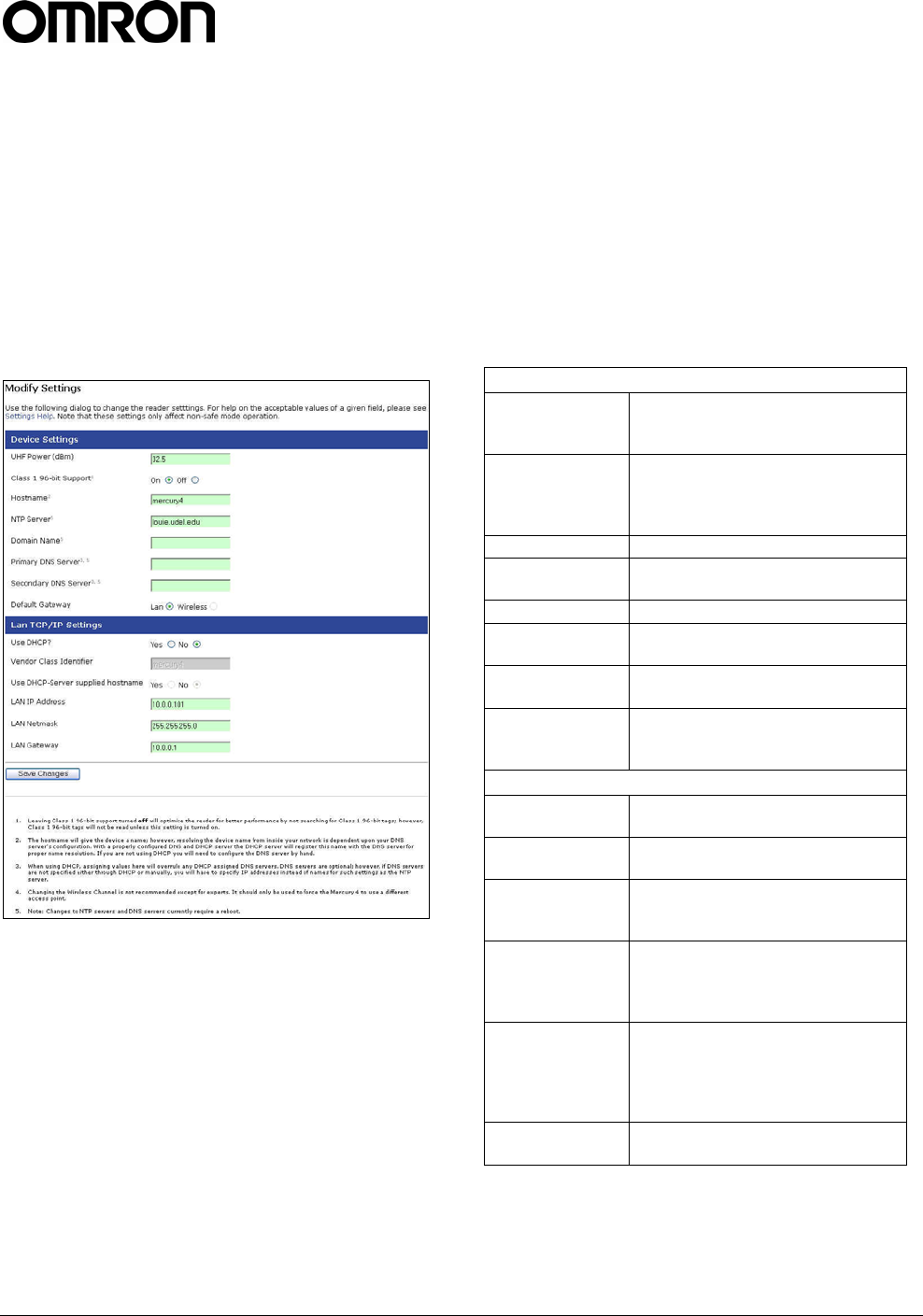
Write Page
Use the Write page to replace the EPC data that is
encoded on a 915 MHz EPC Class 1 tag.
Consider the following guidelines when writing to
tags:
• Always place a tag 0.3–0.6m (1–2ft) from the
antenna when writing data. The tag may be
damaged if it is too close to the antenna.
• Only unlocked 915 MHz tags can be used. The
write function is not supported for 13.56 MHz
tag protocols.
• The data to be written must be exactly 16
hexadecimal characters (numerals from 0–9
and letters from A–F).
• Always place only one tag in the antenna’s
field when writing. If multiple tags are present,
they will all be encoded with the same EPC
data.
• Use the antenna connected to UHF1.
To write data to a tag:
1. Click the Write link on the navigation menu.
The Write page appears.
2. In the top pane, type or paste the 16-character
hexadecimal data to be written to the tag.
3. Highlight the hexadecimal data.
4. Click the Make Update button. A query
designed to write the highlighted data to the
tag appears in the center pane.
5. Place the tag 0.3–0.6m (1–2ft) from the
antenna connected to UHF1.
Verify that no other tags are in the antenna’s
field.
6. Click the Submit Query button to write the
data. If the write was successful, the new tag
data appears in the bottom pane.
To read data from a tag:
1. Display the Write page (click the Write link on
the navigation menu).
V740 RFID READER ANTENNA NOTE. SPECIFICATIONS SUBJECT TO CHANGE WITHOUT NOTICE. REV. 1.1
OPERATION MANUAL 10 of 27 © OMRON CORPORATION 2004
2. Click the Make Select button. A query
designed to read data from the antenna
connected to UHF1 appears in the center
pane.
3. Place the tag to be read within the detection
zone of the antenna.
4. Click the Submit Query button to read tag data.
Query results appear in the bottom pane.
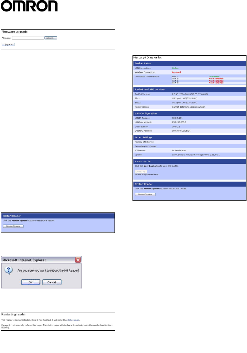
Settings Page
Use the Modify Settings page to change network
settings.
1. Click the Settings link on the navigation menu.
The Modify Settings page appears.
2. Enter the required settings.
3. Click the Save button to save the new settings.
IMPORTANT: Do not disconnect power until
the save process is complete.
The new settings DO NOT take effect until the
Reader is restarted by rebooting the Reader
(see Restarting the Reader on page 12).
Instructions for Modifying the Settings
Changing these parameters changes the Readers
settings used on startup. Both radio settings and
network settings can be modified. Care must be
taken to use correct values or you might be unable
to connect the Reader without restarting into safe
mode.
Static network settings are ignored when in DHCP
mode, and DHCP related settings are ignored
when in static IP mode. Please note that your
network needs to have properly configured DNS
servers if you wish to connect to the Reader via its
hostname. Usually when using DHCP, the DHCP
server will add the hostname to the DNS server’s
database.
Device Settings
UHF Power
(dBm)
UHF Output power in dBm. This
setting must be adjusted carefully
to comply with FCC regulations.
Class 1 96-bit
Support
Radio button that enables 96-bit
tag support. To optimize the
Reader keep this setting turned
off unless it is needed.
Hostname Name of the device
NTP Server Server or servers to use for
network time protocol
Domain Name Network domain name
Primary DNS
Server Primary DNS server
Secondary DNS
Server Secondary DNS server
Default
Gateway
Radio button to select the default
interface for network
communications.
LAN TCP/IP Settings
Use DHCP? Radio button that sets the Reader
to use DHCP.
Vendor Class
Identifier
Extra DHCP parameter for
integration and customization.
Use DHCP
Server supplied
hostname
Set this to yes to allow the DHCP
server to assign the Reader a
hostname.
LAN IP Address
The IP address to use when not
using DHCP. It is specified in
dotted-quad notation. The default
value is 10.0.0.101.
LAN Gateway
When not using DHCP this setting
specifies the default gateway to
use. It is specified in dotted-quad
notation. The default value is
10.0.0.1
LAN Netmask TCP/IP netmask to use. The
default value is 255.255.255.0.
V740 RFID READER ANTENNA NOTE. SPECIFICATIONS SUBJECT TO CHANGE WITHOUT NOTICE. REV. 1.1
OPERATION MANUAL 11 of 27 © OMRON CORPORATION 2004
Firmware Upgrade Page
1. Click the Firmware link on the navigation
menu. The Firmware Upgrade page appears.
2. Place the cursor in the Filename field and type
the complete network pathname of the
firmware file or click the Browse button to
locate the new firmware file.
3. Click the Upgrade button to download the new
firmware to the Reader.
The status frame at the bottom of the page
displays the progress of the upgrade if the web
browser supports automatic page reload. Click
the Refresh button to update the status bar if
the web browser does not support automatic
page reload.
Downloaded firmware IS NOT implemented
until the Reader is restarted.
If an error occurs during the firmware upgrade,
use Safe Mode to recover.
Restart Page
Use the Restart page to restart the Reader.
1. Click the Restart link on the navigation menu;
The Restart Reader page appears.
2. To restart the Reader, click the Restart
System button. The following dialog boa
appears.
3. Click OK. The following message appears and
remains on the screen until the Reader
restarts. Then the Status page appears.
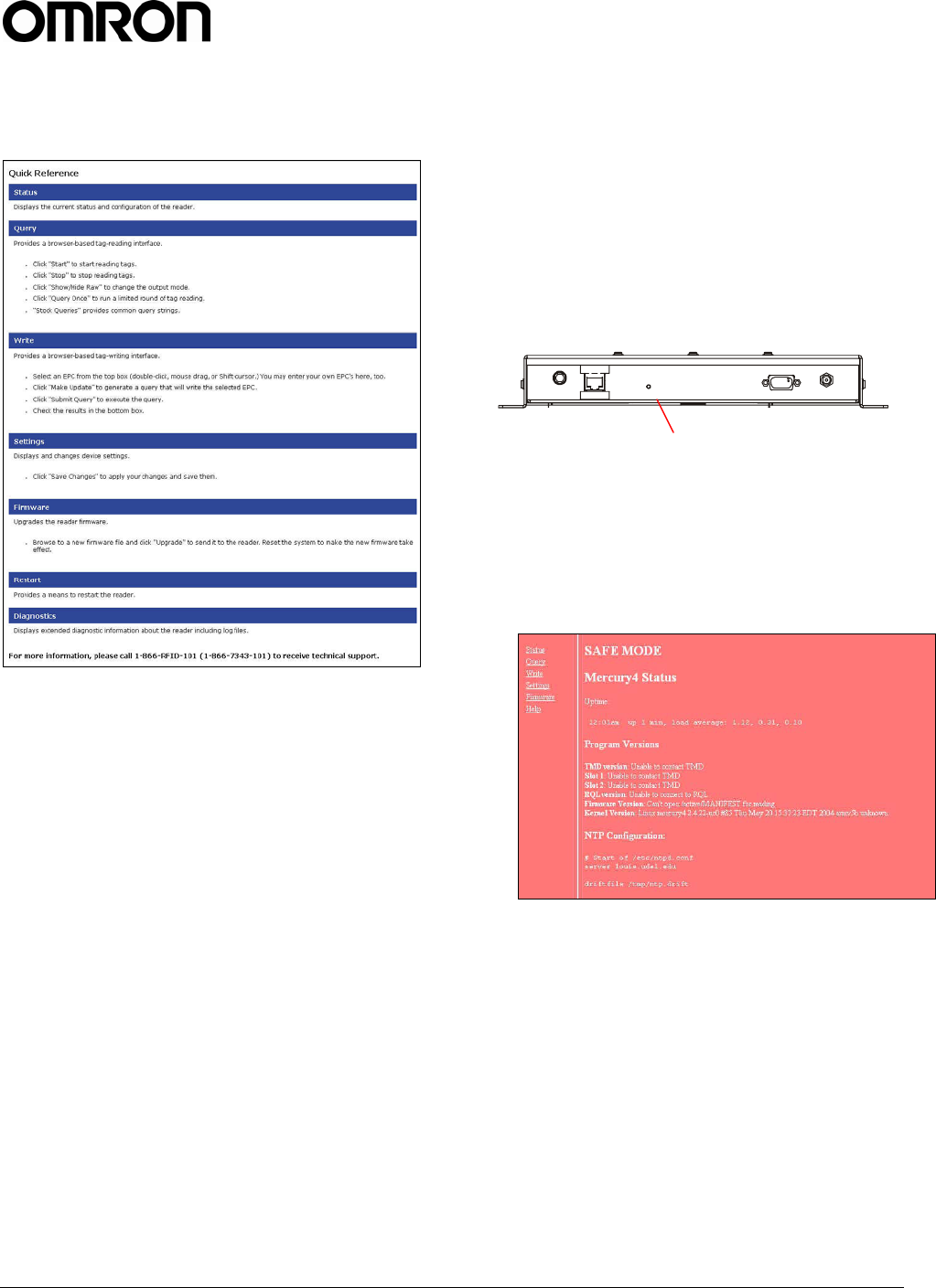
Diagnostics Page
The diagnostics page provides a wealth of
information, including the current settings of the
Reader, comprehensive version information, and
current status of network interfaces.
V740 RFID READER ANTENNA NOTE. SPECIFICATIONS SUBJECT TO CHANGE WITHOUT NOTICE. REV. 1.1
OPERATION MANUAL 12 of 27 © OMRON CORPORATION 2004
Help Page
Use the Help page to view descriptions of system
operations.
Restarting the Reader
Use this procedure to recover from a Reader error.
1. Click the restart link on the navigation menu.
2. Click the restart button and the OK button on
the confirmation dialog.
Wait for at least 60 seconds for the Reader to
boot up. The Power/Heartbeat LED is solid
green while the Reader boots. When the LED
begins blinking, the boot process is complete.
Using Safe Mode
Use the Safe Mode button on the Reader
connector panel to recover from errors that disable
the Reader.
Safe mode operation restores factory default
settings as follows:
Firmware Version: .............. factory installed version
UHF (915 MHz) RF Transmit Power:.................32.5
IP Address:.....................................................DHCP
Hostname: ....................................................... V740
Although the browser-based interface pages are
displayed in red when operating in Safe mode, the
Reader is fully functional. In most cases, the
Reader will need to be reconfigured for operation
with the Reader application after starting in Safe
mode.
1. Disconnect power from the Reader.
2. Depress and hold the Safe Mode button, using
a nonconductive object, while restoring power
to the Reader. Keep the Safe Mode button
depressed until the Reader boots completely
(the green Power/Heartbeat LED blinks).
3. Factory-default settings are restored.
4. Use the browser-based interface to configure
the Reader for use with your system.
This PC must be configured with an IP address
and subnet mask compatible with the Reader
default settings. For example: IP address
10.0.0.10, net mask 255.255.255.0.
5. Click the Settings link on the navigation menu
and verify the new settings.
6. Restart the Reader with the new settings.
Once the restart is complete, the Reader is no
longer in Safe Mode.
Safe Mode button

V740 RFID READER ANTENNA NOTE. SPECIFICATIONS SUBJECT TO CHANGE WITHOUT NOTICE. REV. 1.1
OPERATION MANUAL 13 of 27 © OMRON CORPORATION 2004
Specifications
Electrical
Reader
UHF operating frequency ................... 902–928MHz
Input voltage.........................................24Vdc, 2.0A
Separate Power Supply
Input voltage.......... Nominal 100–240Vac, 50/60Hz
AC line current...................... Nominal 0.5A at 120V
Output voltage ...............Nominal 24Vdc, 2.5A peak
Certified limited power source
Class 2
Environmental
Operating temperature: ... 0° to 40°C (32° to 104°F)
Relative humidity: ........... 0 to 90% non-condensing
Mechanical
Reader
Length............................................. 26.5cm (10.4in)
Width .............................................. 26.6cm (10.4in)
Width (with mounting bracket)........... 30.5cm (12in)
Depth.................................................. 3.8cm (1.5in)
Weight ..................................................1.4kg (3 lbs)
Supported Tag Protocols
915 MHz .............................................. EPC Class 1
EPC Class 0
ISO 18000-6B

V740 RFID READER ANTENNA NOTE. SPECIFICATIONS SUBJECT TO CHANGE WITHOUT NOTICE. REV. 1.1
OPERATION MANUAL 14 of 27 © OMRON CORPORATION 2004
V740
RFID Reader Query
Protocol
Reference Guide
This chapter lays the groundwork for the
communication protocol between client software
running on a remote computer and V740 RFID
Readers. The client software can be any kind of
database system, enterprise software, or user
software.
In this chapter, we discuss the underlying transport
protocol used and present the initial
communication protocol RQL. This protocol is
loosely based on the SQL language with
extensions for a better notion of time. This protocol
was designed for rapid prototyping of applications,
where a full query to the Reader can be
encapsulated in a single line of ASCII text. A
simple polling mechanism exists for automatically
receiving tag events and for testing, a connection
can be mode from a standard telnet client.
Transport Protocol
In the current implementation, TCP/IP is used as
the transport protocol. TCP is a connection-
oriented protocol that provides a reliable, in-order
data transport layer with end-to-end checksums
and flow control.
TCP Connection Setup and
Teardown
A session between client software and the Reader
consists of connection setup, data transactions,
and connection teardown.
At present, all connections are initiated only by the
client software. If, for example, the Reader is
configured to automatically forward events and/or
data to the client software but the client software
has not established a connection, then no attempt
is made by the Reader to contact the client
software to establish a connection. Furthermore, if
an extant connection terminates unexpectedly, the
Reader will not attempt to contact the client
software to re-establish a connection. All
responsibility for opening, maintaining, and closing
the connection during a session rests with client
software.
The client software sets up a TCP socket
connection on Reader port 8080. After connecting
successfully, communication between the client
software and the Reader can proceed as described
below. Once the client software has determined
that communication has concluded, the connection
must be terminated at the TCP level. In order to
prevent synchronization issues, each Reader will
support only one TCP connection.
Other transport protocols may be used to
communicate between the client software and its
subjugate Readers. The application-level protocol
discussed below is neutral with respect to the
transport layer.
Event/Query Protocol
The client software can acquire data from the
Readers in two modes: (a) by requesting specific
data or (b) automatically receive events in another
mode. The two modes are discussed in further
detail in the following subsections.
In order to keep the protocol light but
comprehensive, we specify a small set of
commands that allow the client software to fully
configure the Readers and exploit their capabilities.
This minimal set of commands includes the ability
to request reads based on several relevant criteria
(for example, group reads, range reads, reads by
prefix, and so on). The ability to reset the Reader
database and other control capabilities are also
provided for.
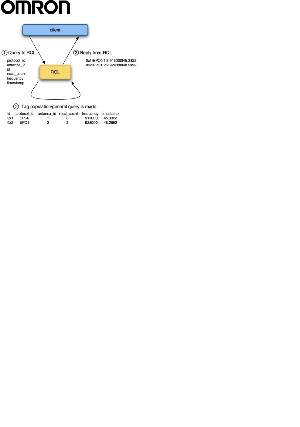
Figure 1 Control flow of RQL
V740 RFID READER ANTENNA NOTE. SPECIFICATIONS SUBJECT TO CHANGE WITHOUT NOTICE. REV. 1.1
OPERATION MANUAL 15 of 27 © OMRON CORPORATION 2004
Client Software
Requests/Functionality
The client software is able to make the following
requests of a Reader:
• Read IDs of all tags within range of all
antennas.
• Read IDs of all tags within range of a given
antenna.
• Read IDs of all tags within a certain subset of
tag IDs within range of all antennas.
• Read IDs of all tags within a certain subset of
tag IDs within range of a specific antenna.
• Read Individual tag IDs within range of a
certain antenna or all antennas.
• Read only the Ids of tags communicating a
given RF communication protocol.
• Return the number of times a given tag was
read per query.
• Read IDs from a variety of tag protocols
• Write IDs to a tag from a variety protocols as
they are supported.
• Read data from a tag from a variety of
protocols as they are supported.
General Observations,
Commands, and Syntax
We note that a Reader behaves very much like
database wherein each individual tag represents
an entry in the database with a given set of
attributes. Due to memory constraints of the
Reader, the system will remove entries from the
database as they are queried. The syntax for
querying against this database is derived from SQL
syntax.
In the simplest case, the client software explicitly
requests data by polling the Readers. The request
protocol is implemented in such a way that the
client software specifies:
What information it needs.
• What subset of tags the Reader should
consider.
• Which read constraints should be applied.
Example commands:
• SELECT id FROM tag_id WHERE
id=0xF00D123456789ABCB0DE AND
antenna_id=1;
Would return a tag only if its tag ID was
0xF00D123456789ABCB0DE.
• SELECT id FROM tag_id WHERE antenna_id=3
OR antenna_id=4 SET time_out=1000;
Would return a tag only if the antenna ID was 3
or 4 and will search for at least 1000ms.
Extended RQL Command
Structure supported by the V740
Extended Command Set for Data and
Write, and Lock operations
ID Read: Identify tags, including anti-collision.
ID Write/Lock: Initialize tag ID, prevent further
changes
Kill, Password: Disable tag, control access to
disable function
Data Read/Write/Lock: Access tag data
(See Table RQL-1 below)

V740 RFID READER ANTENNA NOTE. SPECIFICATIONS SUBJECT TO CHANGE WITHOUT NOTICE. REV. 1.1
OPERATION MANUAL 16 of 27 © OMRON CORPORATION 2004
Table RQL-1
Parameters/Constraints RQL Query Meaning
Read () SELECT id FROM tag_id Reads a tag’s id
Write (new_id) UPDATE tag_id SET id=0x1234 Gives a tag a new
id
ID
Lock (locked) UPDATE tag_id SET locked=1 Locks a tag
Kill (id, password, killed) UPDATE tag_id SET killed=1 WHERE
id=0x1234 AND password=0x1234
Kills a tag
Password (new_password) UPDATE tag_id SET
password=0x1234
Sets the password
of a tag
Read (id, blocknum)
SELECT data FROM tag_data
WHERE id=0x1234 AND
blocknum=12
Reads raw data
from a matching
tag
Write (id, new_value, blocknum)
UPDATE tag_data SET data=0x1234
WHERE id=0x1234 AND
blocknum=12
Writes data to a
specific tag and
memory block
Data
Lock (id, addr, blocknum)
UPDATE tag_data SET locked=1
WHERE id=0x1234 AND
blocknum=12
Locks a block of
memory
With the exception of the ‘ID Read’ command, all
commands are protocol and antenna specific and can
only be used with a single protocol at a time and with
a single antenna at a time. Hence all queries with the
exception ‘ID Read’ need to be constraint to one
protocol and one antenna using, for example
WHERE protocol_id=’CC915’ and
antenna_id=1
A complete example of a complete ‘ID Write’ query
would be
UPDATE tag_id SET
id=0x0123456789ABCDEF WHERE
protocol_id='CC915' AND antenna_id=1.
‘ID Read’ (enumerate tags) is, by definition, a multi-
target command, since it determines what the
individual targets are in the first place.
There are some special cases to the single-target
rule. For example, ID Write is semantically tricky –
what does it mean to target a tag if its target ID is
going to be changing? In the current state of the art,
most protocols do not support addressed ID writes (ID
write targets all tag IDs) or disallow tag ID changes
entirely.
V740 RFID READER ANTENNA NOTE. SPECIFICATIONS SUBJECT TO CHANGE WITHOUT NOTICE. REV. 1.1
OPERATION MANUAL 17 of 27 © OMRON CORPORATION 2004
RQL Table Schema
As was mentioned before, RQL is derived from the SQL language, which allows the user to define arbitrary
tables. RQL has predefined tables according to the schema below. NOTE: Tag_id and Tad_data values are
case-sensitive and are all lowercase only.
Read/Write Tag_id Type Read/Write Tag_data Type
R protocol Int R id Hex String
R antenna Int R/W blocknum Int
R/W id Hex String R/W data Hex String
W killed Int R locked Int
W password Hex String
R/W locked Int
R frequency Int
R dspmicros Int
R timestamp string
Read/Write Tag_id Type
R version String
R supported_p
rotocols
String
Read/Write Settings Type
R current_time String
Detailed Command Structure
Select, Where, Set
The SELECT command is for querying the tag population
of the Reader as well as static variables such as firmware
version and supported protocols. The structure of a
SELECT command is as follows:
SELECT select_list FROM
table_expression [where_specification]
[set_specification];
A where_specification is entered as:
WHERE boolean_expr
boolean_expr can consist of any expression which
evaluates to a boolean value. In many cases, this
expression will be:
expr binary_operator expr
or
unary_operator expr
where binary_operator can be one of =, <, <=, >,
>= , <>, AND, or OR, and unary_operator can
be “NOT”. Parentheses may also be used to create
associations of subexpressions. In the presence of a
WHERE clause, SELECT will not return any rows for
which the WHERE condition does not evaluate to
TRUE.
A set_specification is entered as:
SET expression
In the following we provide some more examples for
the usage of SELECT, WHERE, SET:
• To query a specific tag, given its ePC code, one
can specify a specific tag with id as a hexadecimal
number:
SELECT id FROM tag_id WHERE id=id AND
antenna_id=antenna_id;
SELECT id FROM tag_id WHERE id=id SET
time_out=500;
The Reader returns the tag if the tag is present
followed by an empty event (‘\n’) or an empty

V740 RFID READER ANTENNA NOTE. SPECIFICATIONS SUBJECT TO CHANGE WITHOUT NOTICE. REV. 1.1
OPERATION MANUAL 18 of 27 © OMRON CORPORATION 2004
event (‘\n’) if tags matching the WHERE clause
are not present. The first version requests a read
from a specific antenna, while the second does
not. The second command imposes a time out
constraint of 500ms; i.e., the Reader stops
reading and returns all collected data after 500ms.
The order in which specifying arguments are used
is irrelevant. The default timeout if none is
specified is 250ms.
Any previous statement’s use of the time_out
variable will change the default timeout until a
RESET is asserted. It is important to always use
a timeout in specifying a query to achieve optimal
performance for a given application. This will be
discussed later in section
• To query a specific sub class of tags, given a
range of ePCs:
SELECT id FROM tag_id WHERE
tag_id>min_tag_id AND
tag_id<max_tag_id SET timeout=1000;
The Reader returns the ePCs for all the present
tags between id_min and id_max, which are
hexadecimal values.
• To query all tags:
SELECT id FROM tag_id SET
timeout=2500;
SELECT id FROM tag_id WHERE
antenna_id=1 SET timeout=2500;
The Reader returns all the tags it can find. The
second version requests a read from a specific
antenna, while the first does not.
• The client software specifies which information it
requires in the select_list field of the
SELECT command:
SELECT id, antenna_id FROM tag_id SET
timeout=2500;
SELECT frequency, timestamp, id,
antenna_id FROM tag_id SET
time_out=1000;
Returns the id and antenna_id of every tag in the
field in the first example and the frequency and
time the tag was read at (seconds from the unix
epoch, Jan 1, 1970) in the second example.
Update, Where
The UPDATE command is to write new data into a
table. This can be used to write a new tag_id or sleep
the Reader for a specified amount of time. The
structure of an UPDATE command is as follows:
UPDATE table SET col=expression [,
…] [WHERE wherelist];
table and col entries are provided in Table 1.
The WHERE clause is specified in the same manner
as in the SELECT call above. In the following we
provide some examples for usage of UPDATE:
• To write data for a 64-bit ePC tag id with a
specified lock code, password and block_number:
UPDATE tag_data SET
data=0xFEDCBA9876543210,
block_number=0, lock_code=0xef,
password=0xcd WHERE protocol=’CC915’
AND antenna_id=1;
The Reader returns the tag_id if the write
operation was successful or “Error 128:
Error encountered while attempting to
process tags\n\n” in safe mode, and "Error
128: Error encountered while
attempting to process tags\n\n" in
single query mode otherwise.
• To write for a specified amount of time:
UPDATE tag_data SET
data=0xFEDCBA9876543210,
block_number=1, lock_code=0xef,
password=0xcd, time_out=250 WHERE
protocol=’CC915’ AND antenna_id=1;
Would try to write the tag id for 250ms.
• To sleep the Reader for a specified amount of
time:
UPDATE sleep SET time_out=500;
Would turn off the RF interface for 500ms. This
can be useful for scheduling Readers and
reducing interference.
• Other Updates: kill, locking, password
UPDATE tag_id SET killed=1,
id=0x112233445566778899AABBCC,passwor
d=0x88 WHERE protocol_id='EPC1' AND
antenna_id=4;
UPDATE tag_id SET locked=1,
id=0x0123456789ABCDEF WHERE
protocol_id='EPC1' AND antenna_id=4;
UPDATE tag_id SET password=0x88,
id=0x0123456789ABCDEF WHERE
protocol_id='EPC1' AND antenna_id=4;
Cursors
The client software has the ability to declare cursors
(saved queries), which it can then use to request data
repeatedly using the OPEN or the AUTO_MODE
command. A maximum of 16 cursors can be defined.
To create a cursor:
V740 RFID READER ANTENNA NOTE. SPECIFICATIONS SUBJECT TO CHANGE WITHOUT NOTICE. REV. 1.1
OPERATION MANUAL 19 of 27 © OMRON CORPORATION 2004
DECLARE cursorname
CURSOR FOR query
cursorname — an arbitrary string.
query — a SQL query (SELECT/UPDATE
statement), as defined above.
Example:
DECLARE cursor1 CURSOR FOR SELECT id,
antenna_id FROM tag_id;
DECLARE cursor2 CURSOR FOR UPDATE
tag_data SET data=0xFEDCBA9876543210;
One of the advantages of multiple cursors is that it
allows one to specify unequal times for different
protocols. To give 900 ms to EPC1 and 300 ms to
EPC0 in a 1200 ms search do the following:
DECLARE c1 CURSOR FOR SELECT
read_count, protocol_id, antenna_id,
id FROM tag_id WHERE (antenna_id = 1
OR antenna_id = 2 OR antenna_id = 4)
AND protocol_id='CC915' SET
time_out=900;
DECLARE c2 CURSOR FOR SELECT
read_count, protocol_id, antenna_id,
id FROM tag_id WHERE(antenna_id = 1
OR antenna_id = 3 OR antenna_id = 4)
AND protocol_id='EPC0' SET
time_out=300;
SET AUTO c1,c2 = on;
Fetch
To execute the saved query associated with a cursor,
the client software sends the FETCH command.
FETCH cursorlist;
which performs all actions appropriate to the declared
query and sends the result back.
Example:
FETCH cursor1, cursor2;
Auto Mode
In addition to executing a cursor once with the FETCH
command, the client software may also switch the
Reader into Auto Mode, causing it to repeatedly
execute a cursor indefinitely.
SET auto cursorlist = ON, repeat =
interval;
For example,
DECLARE c CURSOR FOR SELECT id,
antenna_id FROM tag_id SET
time_out=250;
SET auto c = ON, repeat = 500;
Every 500 milliseconds, the Reader spends 250
milliseconds querying for tags. The remaining 250
milliseconds are spent with RF off. This syntax can be
used for controlling the duty cycle of the Reader. For
full Reader utilization, ensure that the value of
time_out is no less than the value of repeat.
The repeated queries can be terminated by sending
the command:
SET auto = OFF;
No other command can be used while Auto Mode is
active.
Close
To close a cursor and free its resources (only 16
cursors may be defined simultaneously). Only one
cursor can be freed at a time. The client software
issues the command:
CLOSE cursorname;
Reset
To reset the Reader RQL server, for example, if the
RQL state is undefined or questionable, use:
RESET;
The command returns the RQL daemon to its initial
state; that is, no cursors are defined and no data has
been read from the field.
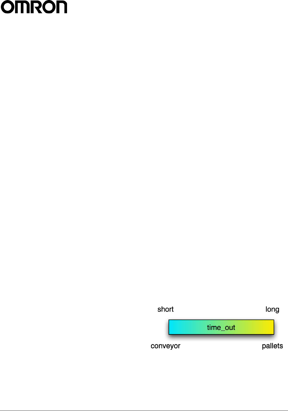
Timeout
The client software can impose a time limit on a read
operation, requesting the Reader to search only for a
limited time (specified in milliseconds). The Reader
may fail to detect some tags if insufficient time is
allocated to the search operation. The time_out is the
parameter used for changing the function of a Reader
and indicates assumptions about the role of the
Reader.
In general, a large time_out should be used for pallets
(>2s), and short time_outs should be used for
conveyor belts (<100ms).
SELECT id FROM tag_id SET
time_out=1000;
V740 RFID READER ANTENNA NOTE. SPECIFICATIONS SUBJECT TO CHANGE WITHOUT NOTICE. REV. 1.1
OPERATION MANUAL 20 of 27 © OMRON CORPORATION 2004
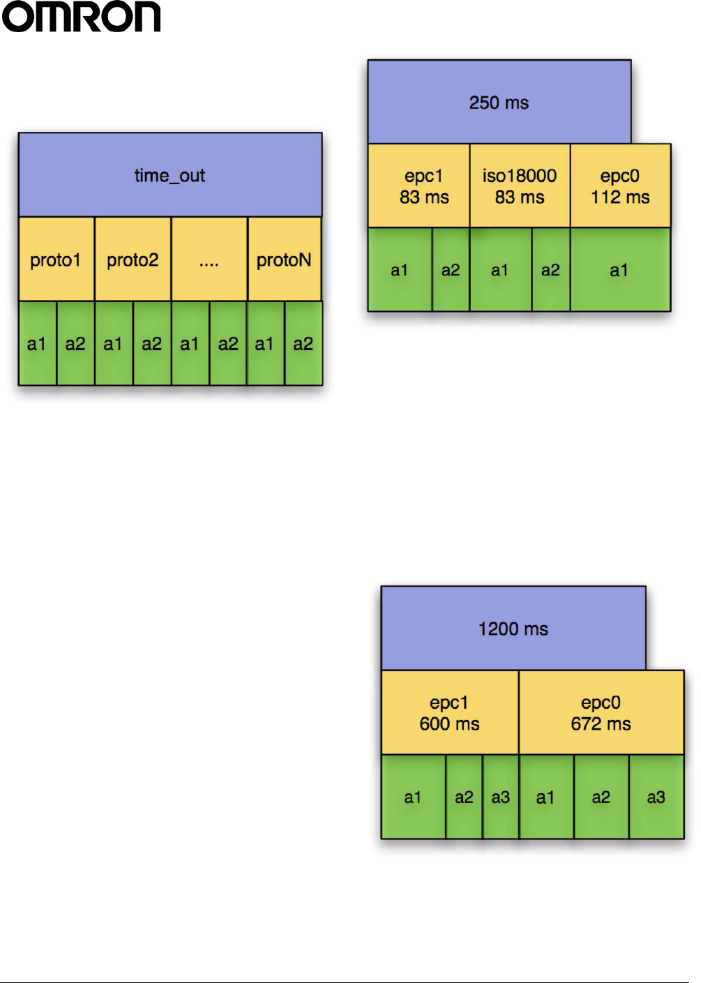
The constraints on the scheduler in the V740 for the
time_out are shown below. Time is equally divided
among the specified protocols, and then divided
among the antennas.
For all protocols except EPC0, the antenna arbitration
algorithm is optimized for the maximizing the read rate
of the tags in the field. For EPC0, at this time, each
antenna will be arbitrated 112ms of search time. Thus,
time division for antennas within a protocol cannot be
specified. It is important in specifying a search to
specify the protocols one is searching on, or else the
Reader will spend time searching for protocols one is
not interested in. For specifying the time to search
over multiple protocols for a single query, it is
important to keep in mind that the time_out parameter
should be specified as the worst case of the multiple
protocols.
minimum time_out =
max{num_epc0*epc0_time_per_tag,num_epc1*ep
c1_time_per_tag,num_iso*num_iso_time_per_tag
,..}x # protocols x # antennas (ms)
e.g. if 40 EPC0 tags takes 1.4 ms per tag and 10
EPC1 takes 16 ms per tag on average. With two
antennas:
minimum time_out =
2 x 2 x max{40*1.4,10*16} = 640 ms.
As another example, if the goal is to search on EPC1
and EPC0 on antennas 1, 2, or 4 for strong 20 tags on
each protocol. The query specified is 'SELECT
read_count, protocol_id, antenna_id, id
FROM tag_id WHERE antenna_id = 1 OR
antenna_id = 2 OR antenna_id = 4'
V740 will search 3 protocols for 250 ms:
EPC0, EPC1, and ISO18000-6b will each get a
83.3ms slot. This will allow all 20 EPC0 tags to be
read, but not all EPC1 tags.
If the EPC0 tags are present only on the 4th antenna,
the Reader will never arbitrate time to this antenna. A
better query would be:
SELECT read_count, protocol_id, antenna_id,
id FROM tag_id WHERE (antenna_id = 1 OR
antenna_id = 2 OR antenna_id = 4) AND
(protocol_id='CC915' OR protocol_id='EPC0')
SET time_out=1200
Both EPC0 and EPC1 will get 600 ms:
each antenna for EPC0 will get 200 ms (above
112ms) should read all 20 EPC0 and 20 EPC1.

V740 RFID READER ANTENNA NOTE. SPECIFICATIONS SUBJECT TO CHANGE WITHOUT NOTICE. REV. 1.1
OPERATION MANUAL 21 of 27 © OMRON CORPORATION 2004
Use of RQL for Scheduled Reads
The V740 uses the Network Time Protocol as a
means to establish absolute time on the Reader. With
that capability in place the Reader is enabled to
execute tag operations that have been scheduled
relative to absolute time. Here is how it works.
First the user declares a cursor, or a set of cursors, in
a way similar to how to you use cursors in auto mode.
To run the query once at a specific time you use a
command of the form:
SET trigger_time <cursor list> =
'<time string>';
To run the query in auto mode over a given interval:
SET auto_time <cursor list> =
'<start time>';
or
SET auto_time <cursor list> =
'<start time>/<stop time>';
The first form here starts the auto mode at a given
time, and then just continues until you stop it, the
same way you'd stop normal auto mode.
The second form runs during the specified interval.
The cursor lists are the normal form of either 1 cursor
"cursor1" or a list of cursors, "cursor1, cursor2,
cursor3..."
The start and stop time are specified in ISO8601 time
strings, of the form
YYYY-MM-DDTHH:mm:SS.DDDDZZZZZ
Where YYYY is the year, MM is the month, DD is the
day, HH is the hour, mm is the minute, SS is the
second, and DDDD is the fraction of a second, and
ZZZZZZ is the time zone. The seconds and fractions
of a second are both optional (but if you want fractions
of a second, you have to have seconds as well). The
time zone can either be specified as GMT or Zulu time
by using a 'Z' or it can be an offset from GMT using
+HH:MM or -HH:MM. For us, in Eastern time, that
would be -05:00.
Some examples:
DECLARE c1 CURSOR FOR SELECT id FROM
tag_id WHERE antenna_id=1 AND
protocol_id='CC915';
DECLARE c2 CURSOR FOR SELECT id FROM
tag_id WHERE antenna_id=2 AND
protocol_id='ISO15693';
To run c1 once on February 14th 2004 at 18:54:50
GMT:
SET trigger_time c1 = '2004-02-
14T18:54:50Z';
To run c1 and c2 both for 10 seconds starting at 2004-
01-20 at 15:37 in Eastern Standard Time:
SET auto_time c1, c2 = '2004-01-
20T15:37-05:00/2004-01-20T15:37:10-
05:00';
Errors
If the Reader is unable to execute a command issued
by the Client Software, the Reader issues an error
message, which has the basic form:
ERROR error_code: string
where error_code is an integer. Error codes are
documented in Table 2.
For example:
DECLARE query1 CURSOR FOR SELECT id
FROM tag_id;
FETCH query2;
Would result in the error message:
ERROR 1 FETCH: Cursor does not exist

V740 RFID READER ANTENNA NOTE. SPECIFICATIONS SUBJECT TO CHANGE WITHOUT NOTICE. REV. 1.1
OPERATION MANUAL 22 of 27 © OMRON CORPORATION 2004
Table 2: Error code
(-100) ERROR_INVALID_ARGUMENTS No protocol specified
(-100) ERROR_INVALID_ARGUMENTS Too many protocols specified
(-100) ERROR_INVALID_ARGUMENTS No antenna specified
(-100) ERROR_INVALID_ARGUMENTS Too many antennas specified
(-100) ERROR_INVALID_ARGUMENTS No antenna specified
(-100) ERROR_INVALID_ARGUMENTS Unknown table
(-100) ERROR_INVALID_ARGUMENTS Cursor already exists
(-100) ERROR_INVALID_ARGUMENTS Unknown setting
(-100) ERROR_INVALID_ARGUMENTS Cursor does not exist
(-100) ERROR_INVALID_ARGUMENTS Unknown field
(-100) ERROR_INVALID_ARGUMENTS Invalid set clause entry
(-100) ERROR_INVALID_ARGUMENTS DELETE: Cursor does not exist
(-100) ERROR_INVALID_ARGUMENTS Invalid set clause entry
(-101) ERROR_INVALID_DATA Unknown setting
(-101) ERROR_INVALID_DATA Time is invalid
(-101) ERROR_INVALID_DATA Unknown protocol ID
(-101) ERROR_INVALID_DATA Invalid command in current mode
(-101) ERROR_INVALID_DATA Time is invalid
(-102) ERROR_REMOTE Error setting ping threshold\n
(-102) ERROR_REMOTE Error setting saved ping threshold
(-102) ERROR_REMOTE Error setting saved IP address
(-102) ERROR_REMOTE Error setting saved gateway
(-102) ERROR_REMOTE Error setting saved netmask
(-102) ERROR_REMOTE Error setting firmware version
(-102) ERROR_REMOTE Error setting safemode version
(-102) ERROR_REMOTE Error setting OS version
(-102) ERROR_REMOTE Error setting supported protocols
(-102) ERROR_REMOTE
Invalid antenna(None of the requested antenna_ids exist in this
installation)
(-102) ERROR_REMOTE
Antenna not connected(None of the requested antenna_ids have
an antenna attached)
(-102) ERROR_REMOTE Error performing query
(-102) ERROR_REMOTE Error getting operation state
(-102) ERROR_REMOTE Invalid antenna(antenna_id does not exist in this installation)
(-102) ERROR_REMOTE
Antenna not connected(antenna_id does not have an antenna
attached)
(-128) ERROR_UNKNOWN Tag data access failed
(-128) ERROR_UNKNOWN Error getting entry
(-128) ERROR_UNKNOWN Error getting ip address entry
(-128) ERROR_UNKNOWN Error getting netmask entry
(-128) ERROR_UNKNOWN Error getting gateway entry

V740 RFID READER ANTENNA NOTE. SPECIFICATIONS SUBJECT TO CHANGE WITHOUT NOTICE. REV. 1.1
OPERATION MANUAL 23 of 27 © OMRON CORPORATION 2004
Protocol Specific Functionality and Parameter Settings
While the standard ID_read and anti-collision searches are supported by practically all offered protocols, hence
no protocol-specific information is required to issue and RQL search. More specific commands, such as
data_read and data_write require protocol specific information when formatting the query and interpreting the
results. The tables below provide that information.
915 MHz EPC Class 1
Parameters /
Constraints
Return Value
(String) Example
Read ()
80 bit (64 bit ID
and 16 bit CRC, hex
format) or 112 bit
(96 bit ID and 16
bit CRC)
SELECT id FROM tag_id WHERE
protocol_id=’CC915’
Write
id: 64 bits
or 80 bits
(hex)
password: 8
bits (hex)
error_code OR new_id UPDATE tag_id SET
id=0x1234567890ABCDEF WHERE
protocol_id=’CC915’ AND
antenna_id=1
ID
Lock ()
error_code OR
success_notification
UPDATE tag_id SET locked=1
WHERE protocol_id=’CC915’
AND antenna_id=1
Kill
id: 64 bits
(hex)
password: 8
bits (hex)
error_code OR
success_notification
UPDATE tag_id SET killed=1
WHERE id=0x1234567890ABCDEF
AND password=0x12 AND
protocol_id=’CC915’ AND
antenna_id=1
Password New_password:
8 bit (hex)
error_code OR
success_notification
UPDATE tag_id SET
password=0x12 WHERE
protocol_id=’CC915’ AND
antenna_id=1
Read N/A
Write N/A
Data
Lock N/A

V740 RFID READER ANTENNA NOTE. SPECIFICATIONS SUBJECT TO CHANGE WITHOUT NOTICE. REV. 1.1
OPERATION MANUAL 24 of 27 © OMRON CORPORATION 2004
915 MHz EPC Class 0
Parameters /
Constraints
Return Value
(String) Example
Read ()
80 bit (64 bit
ID and 16 bit
CRC, hex
format) or 112
bit (96 bit ID
and 16 bit
CRC)
SELECT id FROM tag_id WHERE
protocol_id=’EPC0’
ID Write N/A
Lock N/A
Kill
Id: 64 bits
or 80 bits
(hex)
password: 8
bits (hex)
error_code OR
success_notifi
cation
UPDATE tag_id SET killed=1
WHERE id=0x1234567890ABCDEF AND
password=0x12 AND
protocol_id=’EPC0’ AND
antenna_id=1
Password New_password:
8 bit (hex)
error_code OR
success_notifi
cation
UPDATE tag_id SET password=0x12
WHERE protocol_id=’EPC0’ AND
antenna_id=1
Read N/A
Data Write N/A
Lock N/A

V740 RFID READER ANTENNA NOTE. SPECIFICATIONS SUBJECT TO CHANGE WITHOUT NOTICE. REV. 1.1
OPERATION MANUAL 25 of 27 © OMRON CORPORATION 2004
915 MHz ISO18000-6B
Parameters /
Constraints
Return Value
(String) Example
Read ()
80 bit (64 bit
ID and 16 bit
CRC, hex)
SELECT id FROM tag_id WHERE
protocol_id=’ISO18000-6B’
ID Write N/A
Lock N/A
Kill N/A
Passwor
d N/A
Read
id: 64 bit
(hex)
addr: integer
[0…223]
8 bit (hex) SELECT data FROM tag_data WHERE
id=0x1234567890ABCDEF AND
blocknum=12 AND
protocol_id=’ISO18000-6B’ AND
antenna_id=1
Data Write
id: 64 bit
(hex)
addr: integer
[8…223]
new_value: 8
bit (hex)
error_code OR
success_notifi
cation
UPDATE tag_data SET data=0x12
WHERE id=0x1234567890ABCDEF AND
blocknum=12 AND
protocol_id=’ISO18000-6B’ AND
antenna_id=1
Lock
id: 64 bit
(hex)
addr: integer
[8…223]
error_code OR
success_notifi
cation
UPDATE tag_data SET locked=1
WHERE id=0x1234567890ABCDEF AND
blocknum=12 AND
protocol_id=’ISO18000-6B’ AND
antenna_id=1

V740 RFID READER ANTENNA NOTE. SPECIFICATIONS SUBJECT TO CHANGE WITHOUT NOTICE. REV. 1.1
OPERATION MANUAL 26 of 27 © OMRON CORPORATION 2004
Examples
Example 1
DECLARE query CURSOR FOR SELECT id,
antenna_id FROM tag_id WHERE id =
0x123412341234123412341234;
FETCH query;
could return
0x123412341234123412341234|2
if the tag was read by antenna 2 or
\n
if the tag was not found.
Example 2
To schedule intermittent reads with off times of 1
second starting at a specific time use:
DECLARE sleep1 CURSOR FOR UPDATE
sleep SET time_out=1000;
DECLARE real1 CURSOR FOR SELECT id
FROM tag_id;
SET auto_time real1, sleep1 = '2004-
01-22T12:43:08-05:00';
Example 3
To synchronize two Readers follow the following
instructions.
On Reader 1:
DECLARE cursor_one CURSOR FOR SELECT
id FROM tag_id SET time_out=350;
SET repeat=1000, SET auto_time
cursor_one = 0;
The first Reader will start reading for no less then 350
ms (it will probably run over to roughly 500 ms)
starting at time zero, and it will repeat the command
every 1000 ms.
On Reader 2:
DECLARE cursor_two CURSOR FOR SELECT
id FROM tag_id SET time_out=350;
SET repeat = 1000, SET auto_time
cursor_two = 500;
The second Reader will start reading for no less then
350 ms (it will probably run over to roughly 500 ms)
starting at time 500ms, and it will repeat the command
every 1000 ms.
The effect will be that each Reader will have a 50%
duty cycle with each one only active when the other
one is off.

V740 RFID READER ANTENNA NOTE. SPECIFICATIONS SUBJECT TO CHANGE WITHOUT NOTICE. REV. 1.1
OPERATION MANUAL 27 of 27 © OMRON CORPORATION 2004
Declarations
Regulatory Compliance
EMC......................................47 CFR, Part 15(USA)
....................................................... RS210(Canada)
Safety .......................................................UL 60950
Can/CSA C22.2 No 60950
EN 60950
FCC COMPLIANCE: This equipment complies with Part 15 of
the FCC rules for intentional radiators and Class A digital devices
when installed and used in accordance with the instruction
manual. Following these rules provides reasonable protection
against harmful interference from equipment operated in a
commercial area. This equipment should not be installed in a
residential area as it can radiate radio frequency energy that could
interfere with radio communications, a situation the user would
have to fix at their own expense.
EQUIPMENT MODIFICATION CAUTION: Equipment
changes or modifications not expressly approved by OMRON
Corporation, the party responsible for FCC compliance, could
void the user's authority to operate the equipment and could create
a hazardous condition.
IMPORTANT USER INFORMATION: In order to comply
with FCC requirements for RF exposure safety, a separation
distance of at least 21 cm (8.3in) needs to be maintained between
the radiating elements of the antenna and the bodies of nearby
persons.
Other Declarations
WARRANTY DISCLAIMER: OMRON Corporation makes no
representation or warranty with respect to the contents hereof and
specifically disclaims any implied warranties of merchantability or
fitness for any particular purpose. Further, OMRON Corporation
reserves the right to revise this publication and make changes from
time to time in the content hereof without obligation of OMRON
LLC to notify any person of such revision or changes.
LIMITED RIGHTS NOTICE: For units of the Department of
Defense, all documentation and manuals were developed at
private expense and no part of it was developed using Government
Funds. The restrictions governing the use and disclosure of
technical data marked with this legend are set forth in the
definition of “limited rights” in paragraph (a) (15) of the clause of
DFARS 252.227.7013. Unpublished - rights reserved under the
Copyright Laws of the United States.
TRADEMARK NOTICE: OMRON and the OMRON logo are
trademarks or registered trademarks of OMRON Corporation.
Other product names mentioned herein may be trademarks or
registered trademarks of OMRON Corporation or other
companies.
No part of this guide may be reproduced in any form without
written permission from OMRON Corporation.
OMRON CORPORATION
RFID BUSINESS DEVELOPMEN DEPARTMENT
14th Fl., Gate City Osaki West Tower
1-11-1 Osaki, Shinagawa-ku,
Tokyo 141-0032 Japan
Tel: (81)3-5435-2016/Fax: (81)3-5435-2017
OMRON ELECTRONICS LLC
1 East Commerce Drive, Schaumburg, IL 60173
U.S.A.
Tel: (1)847-843-7900/Fax: (1)847-843-8568
Authorized Distributor:
Up-to-date information on RFID Systems can be accessed at OMRON's web site a
t
http://www.omron.com/card/rfid/