Omron 6CYCIDV6400202 Carrier ID Reader/Writer User Manual USERS MANUAL FOR V640
Omron Corporation Carrier ID Reader/Writer USERS MANUAL FOR V640
Omron >
Contents
- 1. USERS MANUAL ANTENNA FOR V640
- 2. USERS MANUAL RF TRANSMITTER FOR V640
- 3. USERS MANUAL FOR V640
- 4. Manual Part One
USERS MANUAL FOR V640
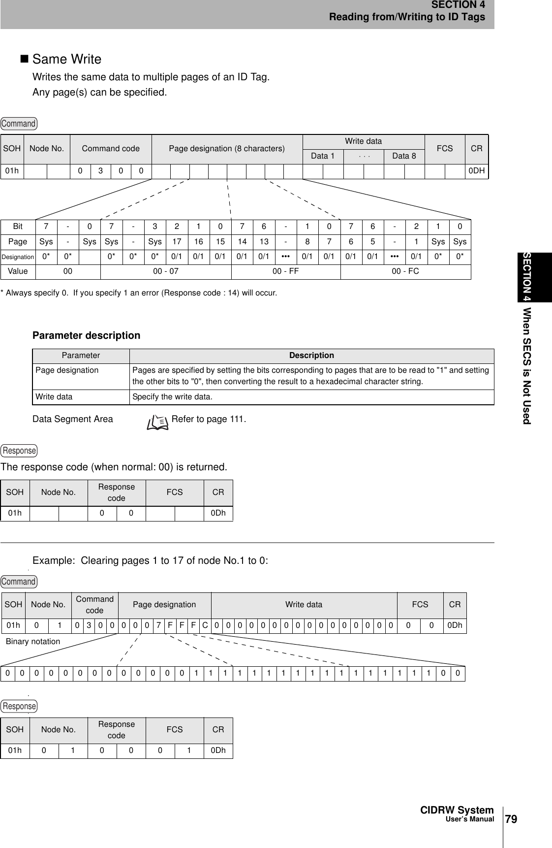
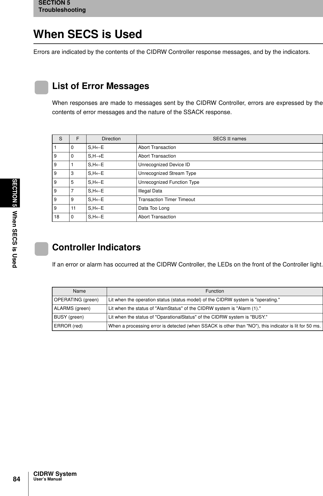
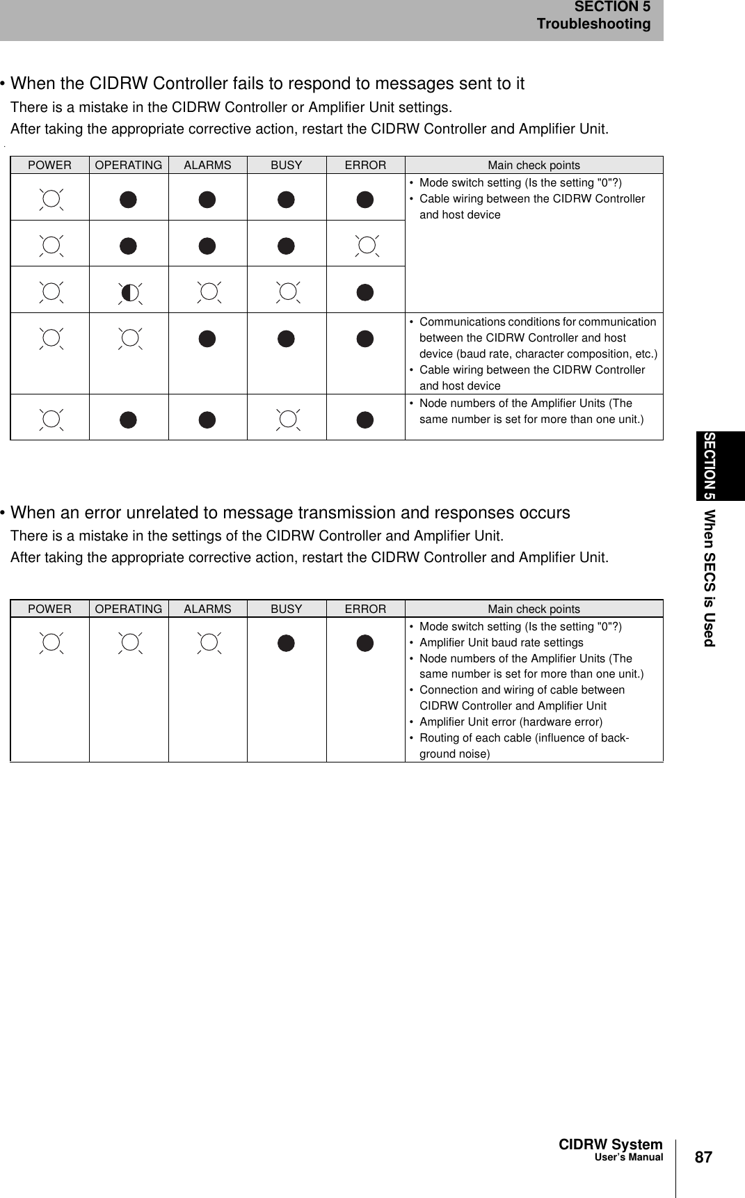
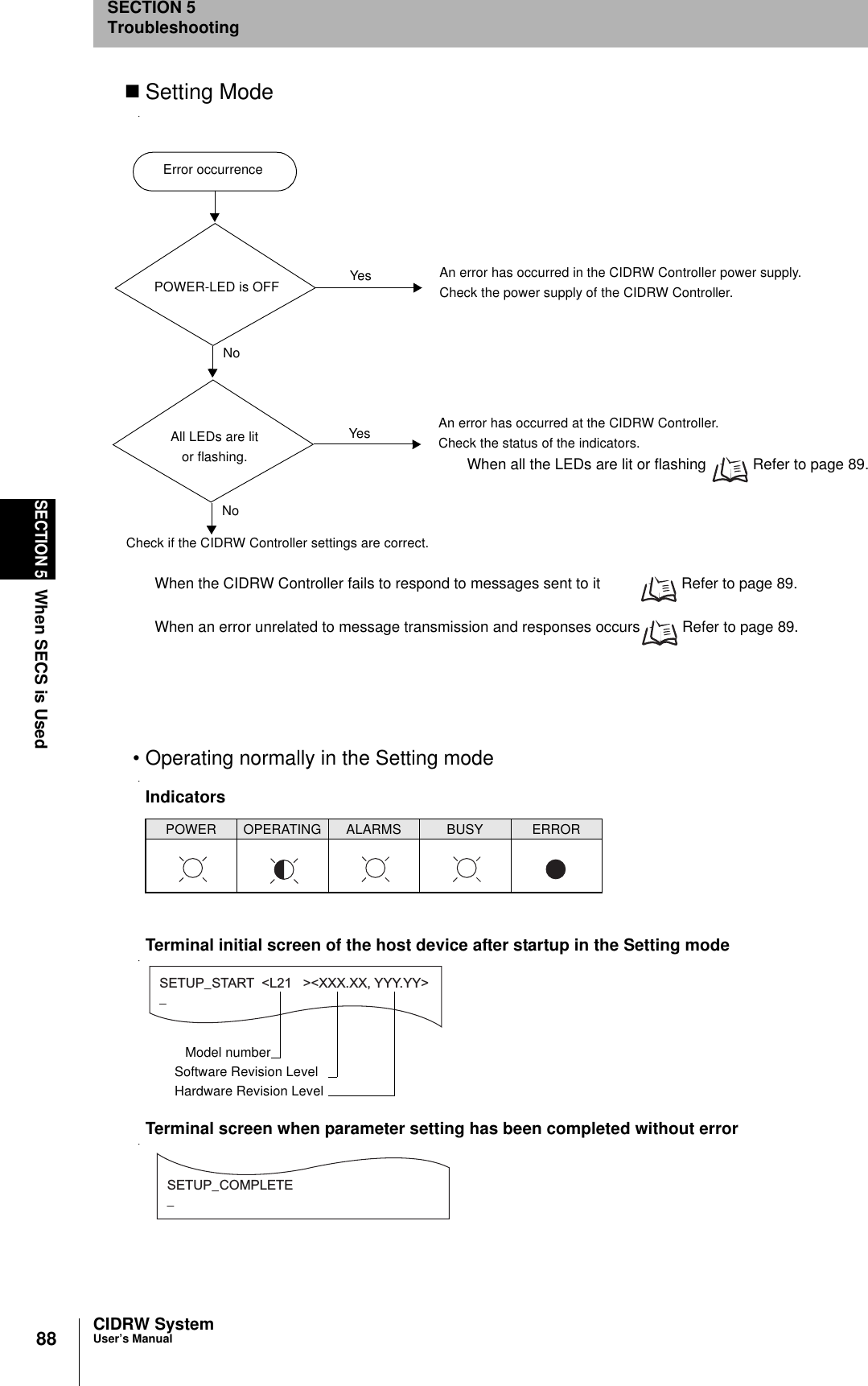
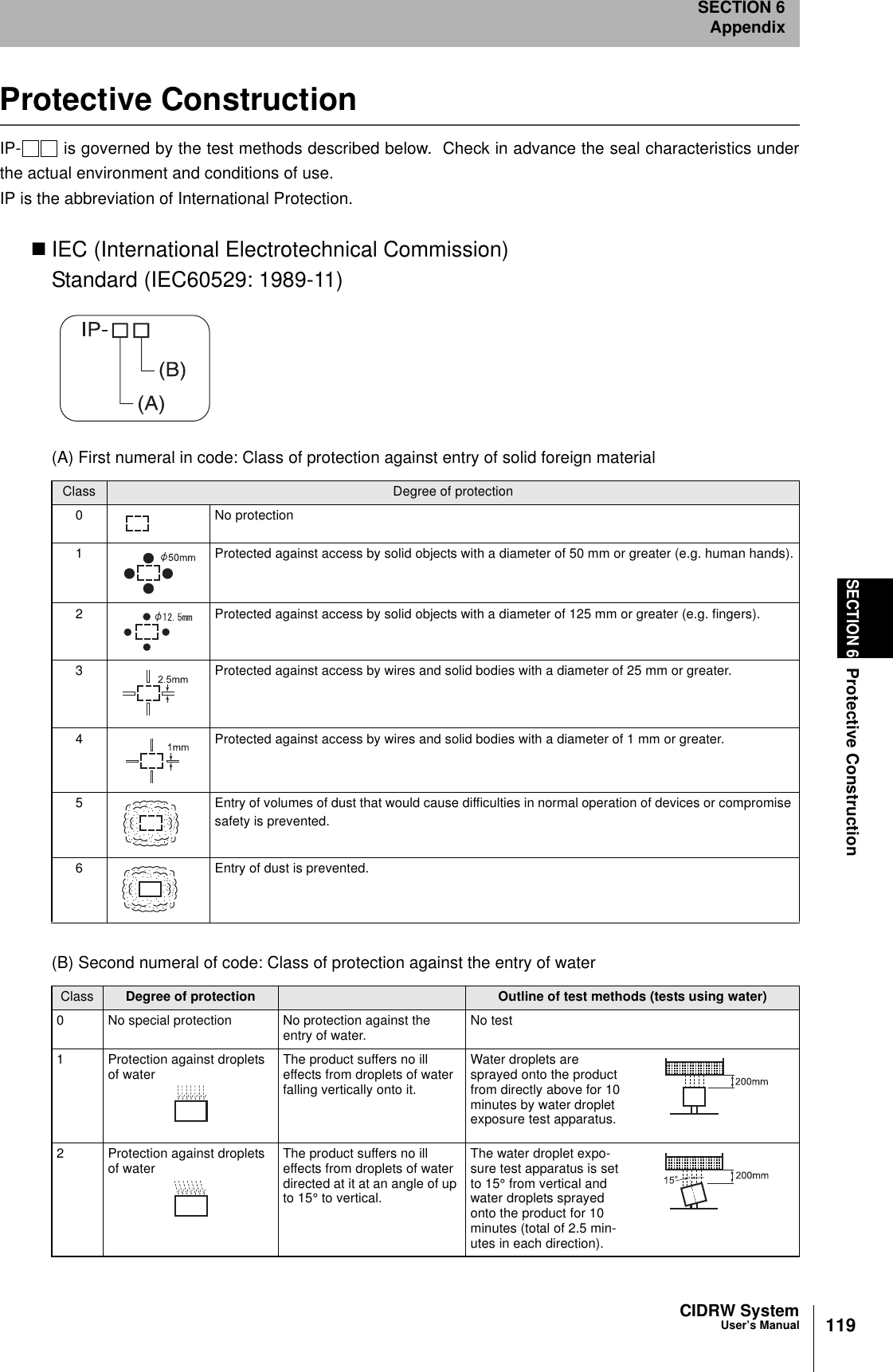
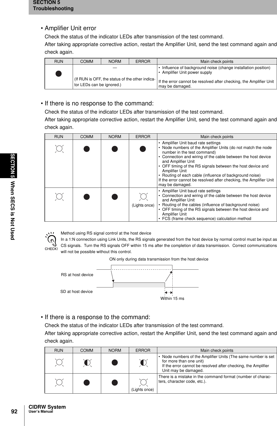
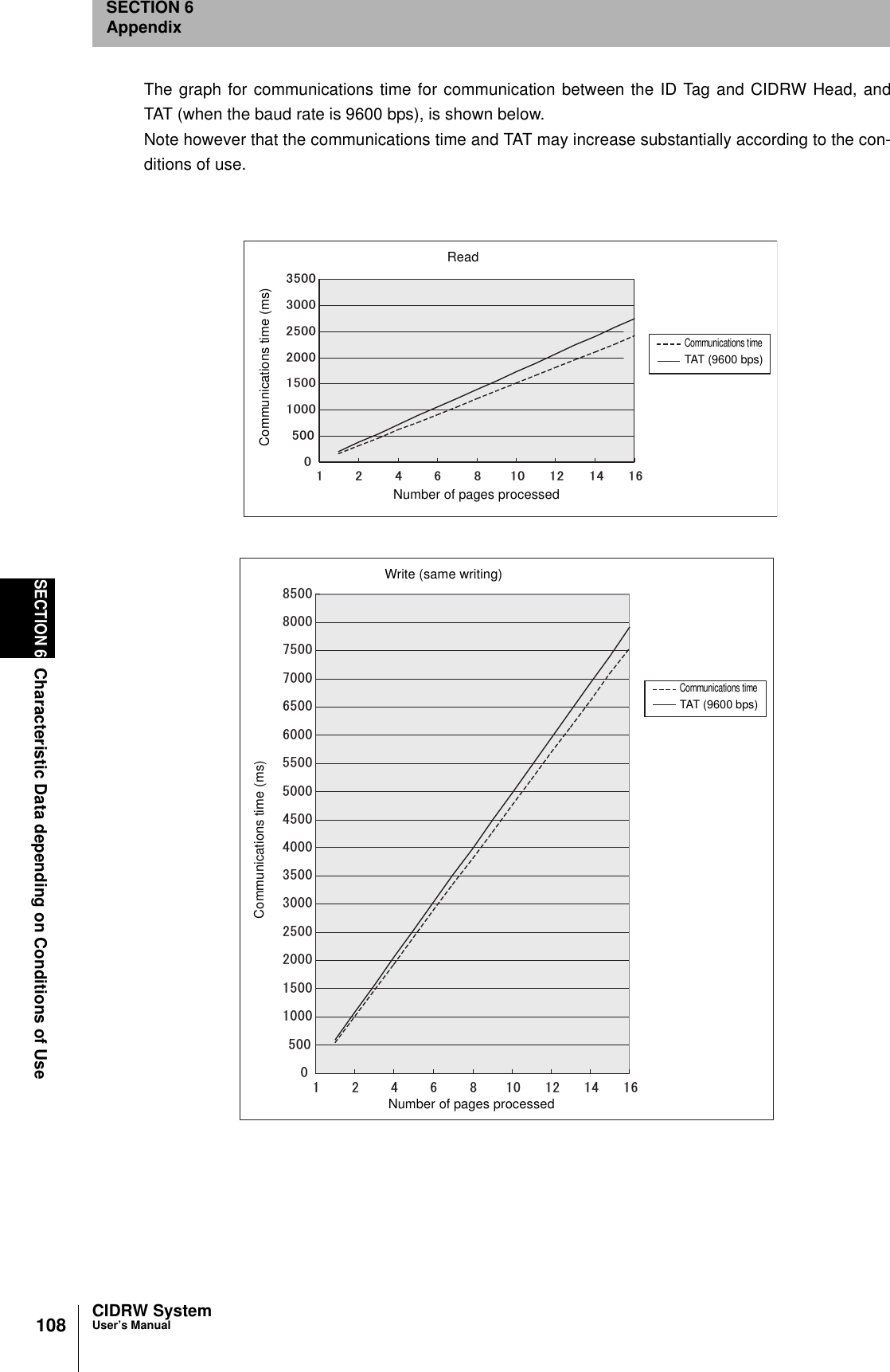
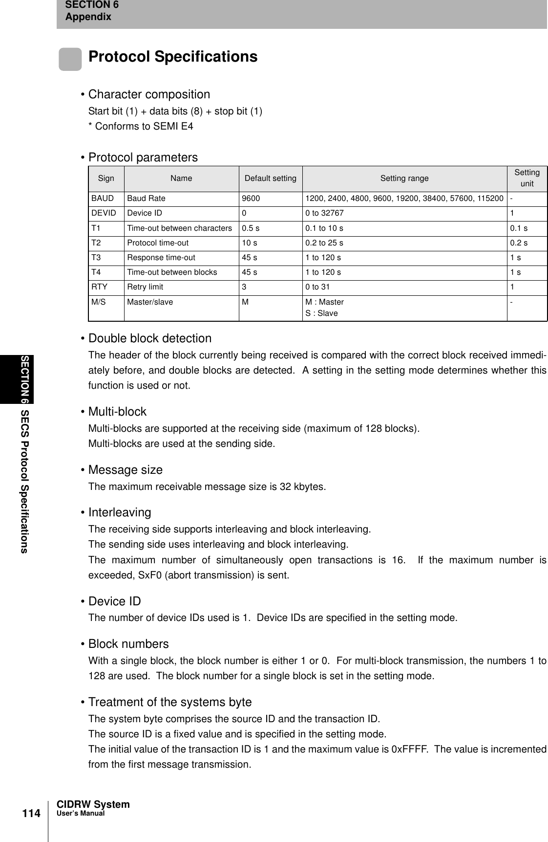
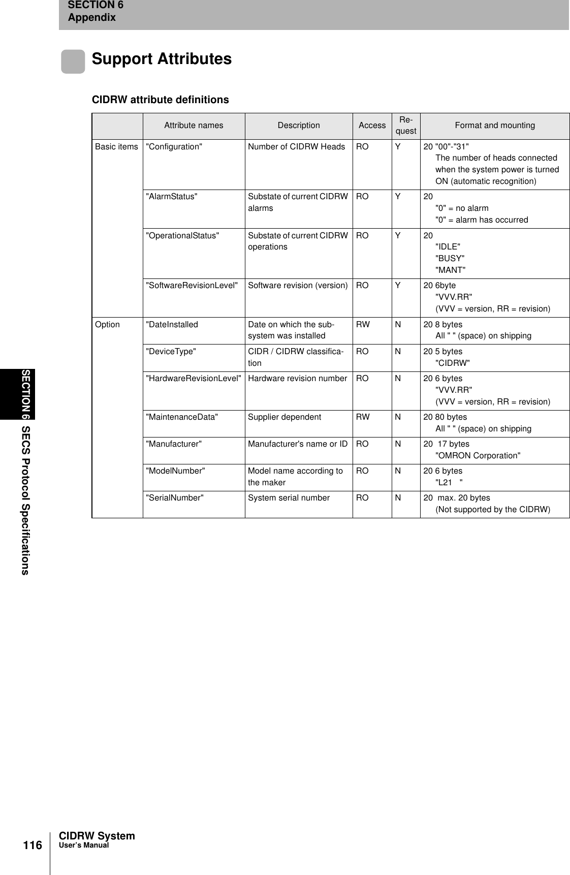
![89CIDRW SystemUser’s ManualSECTION 5When SECS is UsedSECTION 5Troubleshooting• When all the LEDs are lit or flashingAn error has occurred in the CIDRW Controller. After taking appropriate corrective action, restart theCIDRW Controller and check the indicators.• When the CIDRW Controller responds to a message transmissionThere is a mistake in the CIDRW Controller settings or the sent parameters. After taking appropriatecorrective action, restart the CIDRW Controller and check the indicators.• When the CIDRW Controller fails to respond to messages sent to itThere is a mistake in the CIDRW Controller settings or the sent parameters. After taking appropriatecorrective action, restart the CIDRW Controller and check the indicators.• When an error unrelated to message transmission and responses occursThere is a mistake in the settings of the CIDRW Controller or Amplifier Unit. After taking appropriatecorrective action, restart the CIDRW Controller and Amplifier Unit and check the indicators.POWER OPERATING ALARMS BUSY ERROR Main check points• Supply of 24 VDC power• The CIDRW Controller may be damaged.• Mode switch setting (Is the setting "3"?)If the error cannot be resolved after checking, the CIDRW Controller may be damaged.• The CIDRW Controller may be damaged.POWER OPERATING ALARMS BUSY ERROR Main check points• Sent parameters (Are the parameters cor-rect? Are the settings correct?)Response ContentsSETUP_FAILED [ ] The parameters are not updated. The figure in square brackets [ ] indicates the line number where the error was first detected. If a parity error is detected in the received characters, this figure is [0].POWER OPERATING ALARMS BUSY ERROR Main check points• Transmission parameters (Are the parameters correct?)• Communications conditions for communication between the CIDRW Controller and the host device (baud rate, character composition, etc.)• Mode switch setting (Is the setting "3"?)POWER OPERATING ALARMS BUSY ERROR Main check points• Mode switch setting (Is the setting "3"?)](https://usermanual.wiki/Omron/6CYCIDV6400202.USERS-MANUAL-FOR-V640/User-Guide-301174-Page-27.png)
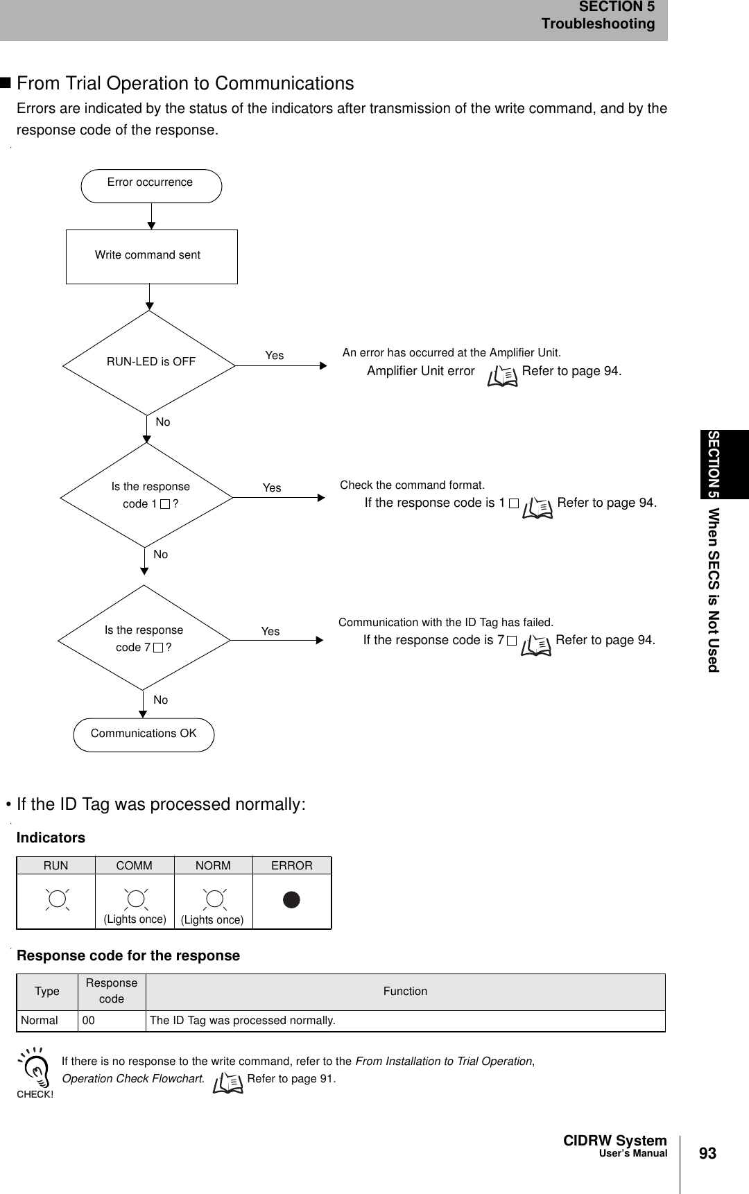
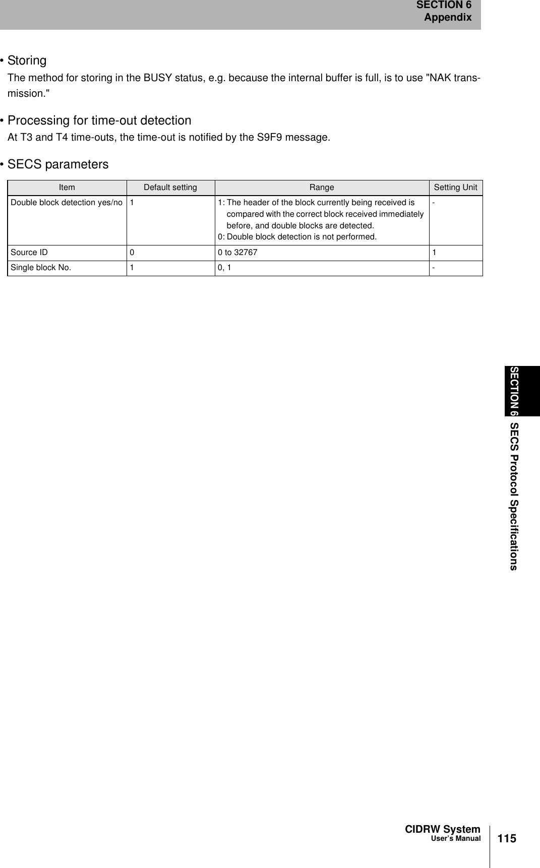
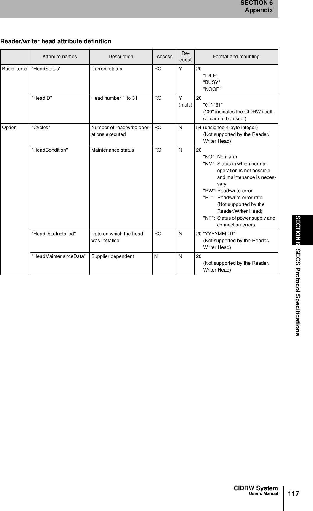
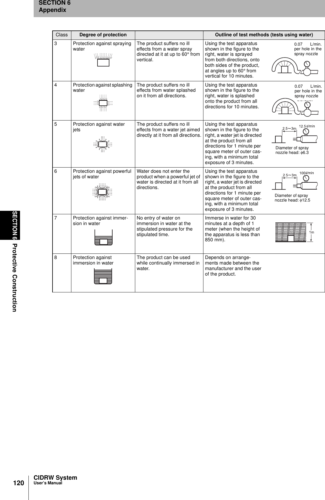
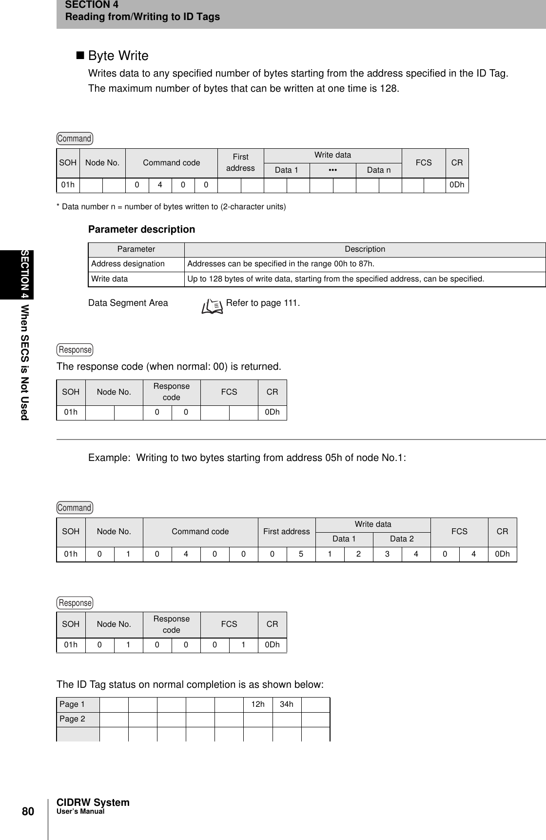
![118SECTION 6ASCII Code TableCIDRW SystemUser’s ManualSECTION 6AppendixASCII Code TableLeftmostbitsRight-most bitsb8 - b50000 1001 0010 0011 0100 0101 0110 0111 1000 1101 1010 1011 1100 1101 1110 1111b4 - b1RowLine0 12 3 4 5 6 7 8 9 10 11 12 13 14 150000 0NUL TC7(DLE)(SP) 0 @ P ` pUndefined Undefined Undefined0001 1TC1(SOH) DC1!1AQaq0010 2TC2(STX) DC2"2BRbr0011 3TC3(ETX) DC3#3CScs0100 4TC4(EOT) DC4$4DTdt0101 5TC5(NEQ) TC8(NAK)%5EUe u0110 6TC6(ACK) TC9(SYN)&6FVf v0111 7BEL TC10(ETB)'7GWgw1000 5FE0(BS) CAN(8HXhx1001 9FE1(HT) EM)9IYiy1010 10FE2(LF) SUB*:JZjz1011 11FE3(VT) ESC+;K[k{1100 12FE4(FF) IS4(FS),<L\ l |1101 13FE5(CR) IS3(GS)-=M]m}1110 14S0 IS2(RS).>N^nÅP1111 15S1 IS1(US)/?OÅQ oDEL](https://usermanual.wiki/Omron/6CYCIDV6400202.USERS-MANUAL-FOR-V640/User-Guide-301174-Page-56.png)