Omron 6CYCIDV6400202 Carrier ID Reader/Writer User Manual USERS MANUAL FOR V640
Omron Corporation Carrier ID Reader/Writer USERS MANUAL FOR V640
Omron >
Contents
- 1. USERS MANUAL ANTENNA FOR V640
- 2. USERS MANUAL RF TRANSMITTER FOR V640
- 3. USERS MANUAL FOR V640
- 4. Manual Part One
USERS MANUAL FOR V640

SECTION 4
Reading from/Writing to ID Tags
63
CIDRW System
User’s Manual
SECTION 4
Reading from/Writing to ID Tags
When SECS is Used 64
When SECS is Not Used 74
64
SECTION 4
When SECS is Used
CIDRW System
User’s Manual
SECTION 4
Reading from/Writing to ID Tags
When SECS is Used
The SEMI standards are subject to revision: you must refer to the actual standards.
• SEMI E99 THE CARRIER ID READER/WRITER FUNCTIONAL STANDARD
• SEMI E5 EQUIPMENT COMMUNICATION STANDARD 2 MESSAGE CONTENT (SECS II)
• SEMI E4 EQUIPMENT COMMUNICATION STANDARD 1 MESSAGE TRANSFER (SECS I)
SECS Protocol Specifications Refer to page 113.
Message Specifications
List of Error Messages Refer to page 84.
List of Messages Used
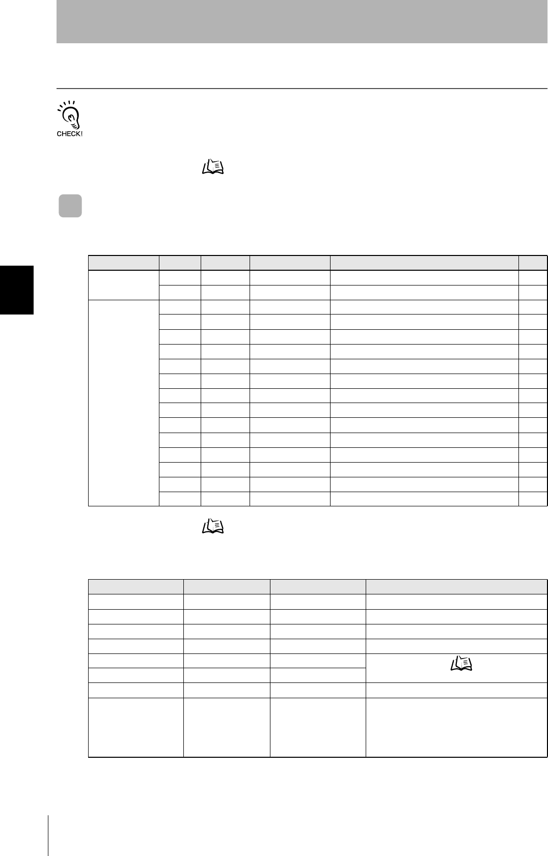
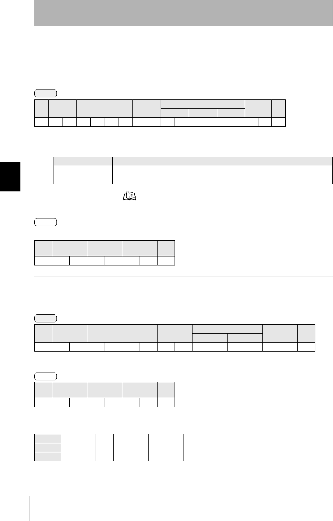
Classification S F Direction SECS II names See
General purpose
messages
11 S,H→E,reply Are You There Request p.66
12 S,H←E On Line Data p.66
CIDRW system
messages
18 1 S,H→E,reply Read Attribute Request p.66
18 2 S,H←E Read Attribute Data p.66
18 3 S,H→E,reply Write Attribute Request p.67
18 4 S,H←E Write Attribute Acknowledge p.67
18 5 S,H→E,reply Read Request p.68
18 6 S,H←E Read Data p.68
18 7 S,H→E,reply Write Request p.69
18 8 S,H←E Write Acknowledge p.69
18 9 S,H→E,reply Read ID Request p.69
18 10 S,H←E Read ID Data p.69
18 11 S,H→E,reply Write ID Request p.70
18 12 S,H←E Write ID Acknowledge p.70
18 13 S,H→E,reply Subsystem Command Request p.70
18 14 S,H←E Subsystem Command Acknowledge p.70
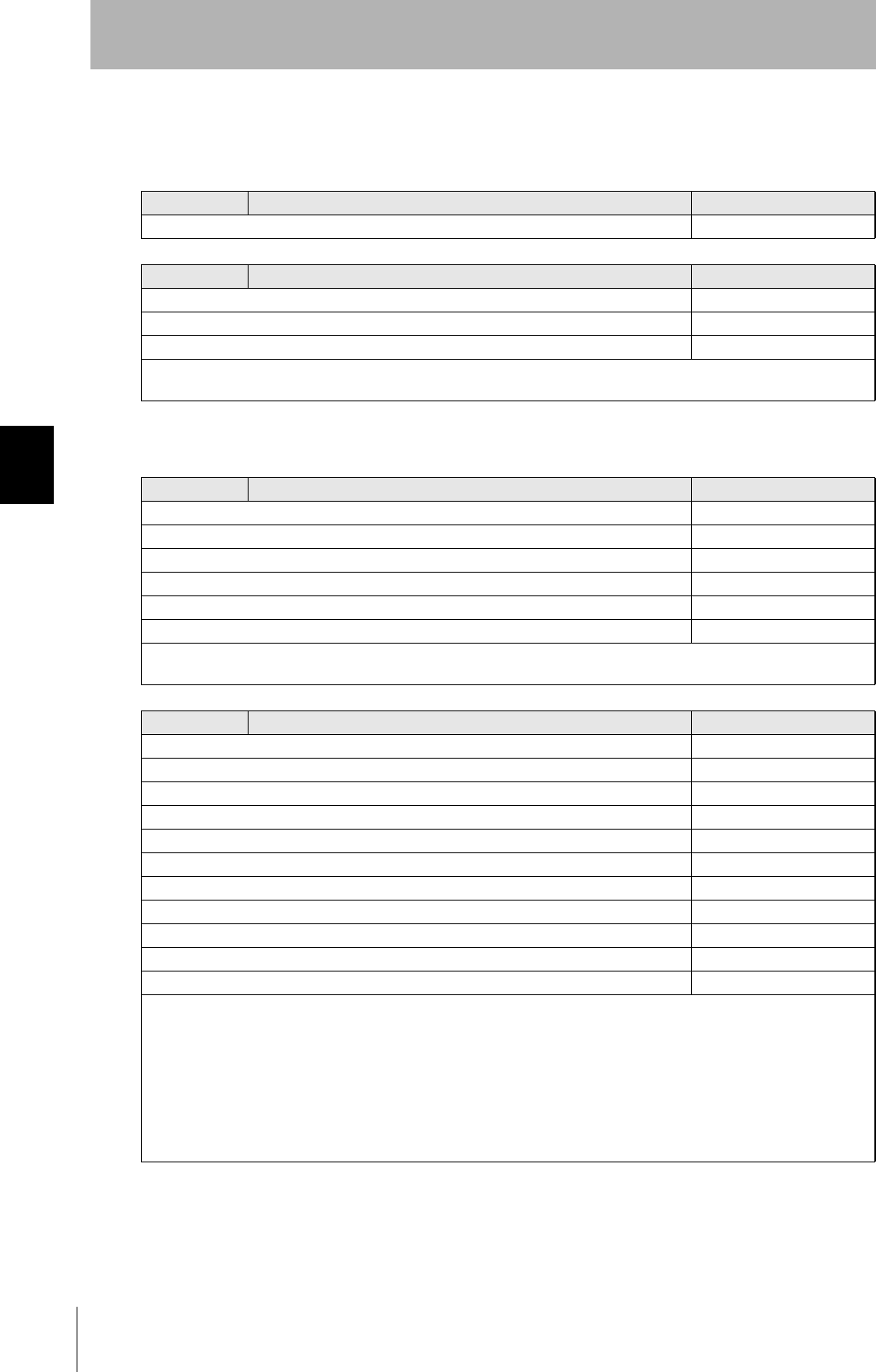
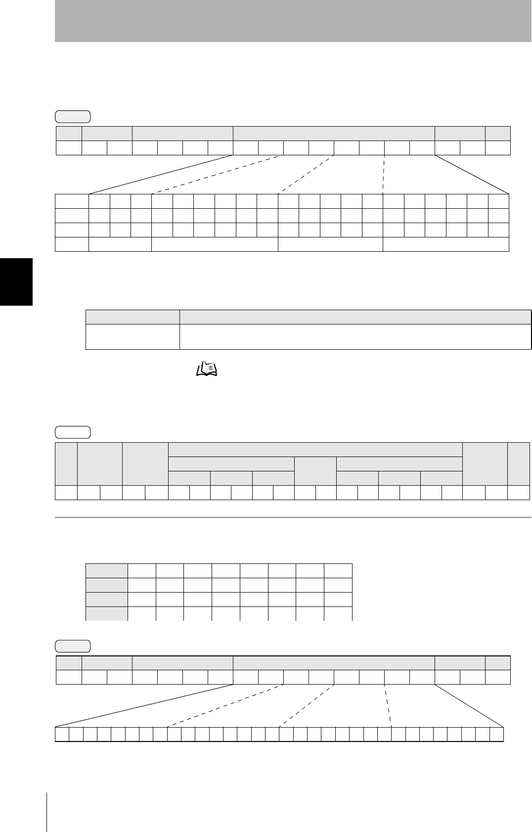
Data Item Dictionary
SECS II data items Name Format Value
ATTRID Attribute ID 20 Attribute name
ATTRVAL Attribute value 20 Attribute value
MID Carrier ID 20 All characters 00H-0FFH
DATA Data 20 All characters 00H-0FFH
DATALENGTH DataSize 52 Data Segment Area Refer to page 48.
DATASEG DataSeg 20
STATUS PM information 20 "NE": Normally executed
SSACK Result status 20 "NO": Normal
"EE": Execution error *3
"CE": Communications error
"HE": Hardware error *3
"TE": Tag error *3

65
CIDRW System
User’s Manual
SECTION 4
When SECS is Used
SECTION 4
Reading from/Writing to ID Tags
*1: "PS" is an expansion command for this unit.
*2: When the TARGET ID is "00" (CIDRW), this is a zero length item.
*3: "EE," "HE," and "TE" are used only with S18F6, S18F8, S18F10, and S18F12.
S9F7 responses
An S9F7 response is given when a message in an illegal format is received from the host device.
"Illegal format" here means that there is a problem with the message composition, such as illegal attributes, or insuffi-
cient or too many items. If other problems relating to the item contents arise, the response is SSACK = "CE" (commu-
nications error).
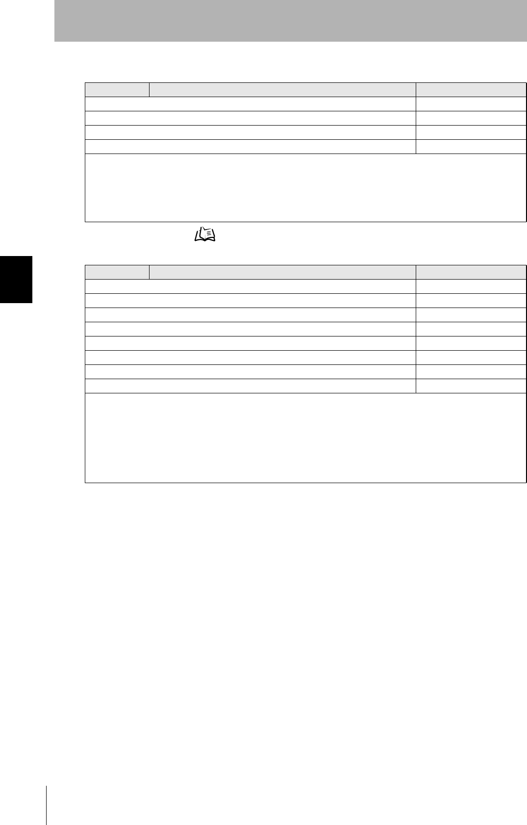
List of STATUS Status L,4
1.<PMInformation>
2.<AlarmStatus>
3.<OperationalStatus>
4.<HeadStatus> *2
The STATUS values are included in the PM infor-
mation.
CPVAL State request 20 "OP", "MT", "PS" *1
TARGETID Target ID 20 "00"-"31"
"00" indicates the CIDRW Controller itself.
SSCMD Subsystem com-
mands
20 "ChangeState"
"GetStatus"
"PerformDiagnostics"
"Reset"
Data Item Dictionary
SECS II data items Name Format Value
66
SECTION 4
When SECS is Used
CIDRW System
User’s Manual
SECTION 4
Reading from/Writing to ID Tags
Specifications for Each Stream/Function
• Online check
• Get attributes
S1,F1 Are You There Request S,H→E,reply
Header only
S1,F2 On Line Data S,H←E
L,2
1.<MDLN>
2.<SOFTREV>
• Set MDLN (model number).
• Set SOFTREV (software revision level).
S18,F1 Read Attribute Request S,H→E,reply
L,2
1.<TARGETID> "00"-"31"
2.L,n
1.<ATTRID1>
⋅
n.<ATTRIDn>
• The setting for reading all attributes (CIDRW Controller or heads) is n = 0.
S18,F2 Read Attribute Data S,H←E
L,4
1.<TARGETID> "00"-"31"
2.<SSACK>
3.L,n
1.<ATTRVAL1>
⋅
n.<ATTRVALn>
4.L,s
1.<STATUS1>
⋅
s.<STATUSs>
• The order of the attribute data corresponds to the attribute ID specified by S18, F1.
When reading of all attributes is specified, unsupported attribute items (ATTRVAL) are omitted.
• When the specified target is invalid:
n = 0, s = 0, SSACK = "CE" communications error
• When one or more undefined attributes are included:
n = 0, s = 0, SSACK = "CE" communications error
• When head attributes are specified with TARGET = "00" or CIDRW Controller attributes are specified with TARGET <> "00":
n = 0, s = 0, SSACK = "CE" communications error
• If the status of SSACK is other than "NO" (normal), the List of Status will comprise zero items.

67
CIDRW System
User’s Manual
SECTION 4
When SECS is Used
SECTION 4
Reading from/Writing to ID Tags
• Set attributes
F18,F3 Write Attribute Request S,H→E,reply
L,2
1.<TARGETID> "00" (fixed)
2.L,n
1.L,2
1.<ATTRID1>
2.<ATTRVAL1>
n.L,2
1.<ATTRIDn>
2,<ATTRVALn>
Since the attributes for heads are all RO in this system, the target ID is fixed as "00".
S18,F4 Write Attribute Acknowledge S,H←E
L,3
1.<TARGETID> "00" (fixed)
2.<SSACK>
3.L,s
1.<STATUS1>
⋅
s.<STATUSs>
• When the specified target is invalid:
s = 0, SSACK = "CE" communications error
• When one or more undefined attributes or RO attributes are included:
s = 0, SSACK = "CE" communications error
• When illegal attribute data is specified:
s = 0, SSACK = "CE" communications error
• If the status of SSACK is other than "NO" (normal), the List of Status will comprise zero items.
68
SECTION 4
When SECS is Used
CIDRW System
User’s Manual
SECTION 4
Reading from/Writing to ID Tags
•Read data
Data Segment Area Refer to page 111.
S18,F5 Read Request S,H→E,reply
L,3
1.<TARGETID> "01"-"31"
2.<DATASEG>
3.<DATALENGTH>
• When the data of all segments is batch read, both DATASEG and DATALENGTH are omitted (they are zero length items).
• When all the data for a particular segment is read, DATALENGTH is omitted (it is a zero length item).
• When DATASEG and DATALENGTH are specified, it is not permissible to specify a DATALENGTH that exceeds the maxi-
mum length of the relevant DATASEG.
• If a DATALENGTH that is under the set length for DATASEG is specified, only the data corresponding to the specified
DATALENGTH is read.
S18,F6 Read Data S,H→E,reply
L,4
1.<TARGETID> "01"-"31"
2.<SSACK>
3.<DATA>
4.L,s
1.<STATUS1>
⋅
s.<STATUSs>
• When the specified target is invalid:
DATA item length = 0, s = 0, SSACK = "CE" communications error
• When an undefined DATASEG is specified, or the DATALENGTH is illegal:
DATA item length = 0, s = 0,
SSACK = "CE" communications error
• When reading of all segment data is specified in a system where the data segment is not defined:
DATA length = 0, SSACK = "NO"
• If the status of SSACK is other than "NO" (normal), the List of Status will comprise zero items.
69
CIDRW System
User’s Manual
SECTION 4
When SECS is Used
SECTION 4
Reading from/Writing to ID Tags
• Write data
Data Segment Area Refer to page 111.
• Read ID
Data Segment Area Refer to page 111.
S18,F7 Write Request S,H→E,reply
L,4
1.<TARGETID> "01"-"31"
2.<DATASEG>
3.<DATALENGTH>
4.<DATA>
• When the data for all segments is batch written, both DATASEG and DATALENGTH are omitted (they are zero length items).
• When all the data for a particular segment is written, DATALENGTH is omitted (it is a zero length item).
• When DATASEG and DATALENGTH are specified, it is not permissible to specify a DATALENGTH that exceeds the maxi-
mum length of the relevant DATASEG.
• If a DATALENGTH that is under the set length for DATASEG is specified, only the data corresponding to the specified
DATALENGTH is written, compressed into the smaller addresses.
• The item lengths of DATASEG and DATA must be matched.
• If DATASEG and DATALENGTH are both omitted (made zero length items), the length of DATA must match the total of the
set lengths of all segments.
S18,F8 Write Acknowledge S,H←E
L,3
1.<TARGETID> "01"-"31"
2.<SSACK>
3.L,s
1.<STATUS1>
⋅
s.<STATUSs>
• When the specified target is invalid:
s = 0, SSACK = "CE" communications error
• When DATASEG and DATALENGTH are illegal:
s = 0, SSACK = "CE" communications error
• If the status of SSACK is other than "NO" (normal), the List of Status will comprise zero items.
S18,F9 Read ID Request S,H→E,reply
1.<TARGETID> "01"-"31"
S18,F10 Read ID Data S,H←E
L,4
1.<TARGETID> "01"-"31"
2.<SSACK>
3.<MID>
4.L,s
1.<STATUS1>
⋅
s.<STATUSs>
• When the specified target is invalid:
s = 0, MID item length = 0, SSACK = "CE" communications error
• If the status of SSACK is other than "NO" (normal), the List of Status will comprise zero items.
70
SECTION 4
When SECS is Used
CIDRW System
User’s Manual
SECTION 4
Reading from/Writing to ID Tags
• Write ID
Data Segment Area Refer to page 111.
• Subsystem command (ChangeState)
S18,F11 Write ID Request S,H→E,reply
L,2
1.<TARGETID> "01"-"31"
2.<MID>
• If an MID that is under the set ID length is specified, the data is compressed into the smaller addresses, and NULL (0x00) is
written as the remaining data.
S18,F12 Write ID Acknowledge S,H←E
L,3
1.<TARGETID> "01"-"31"
2.<SSACK>
3.L,s
1.<STATUS1>
⋅
s.<STATUSs>
• When the specified target is invalid:
s = 0, SSACK = "CE" communications error
• When there is an MID length error:
s = 0, SSACK = "CE" communications error
• If the status of SSACK is other than "NO" (normal), the List of Status will comprise zero items.
S18,F13 Subsystem Command Request (ChangeState) S,H→E,reply
L,3
1.<TARGETID> "00" (fixed)
2.<SSCMD> "ChangeState"
3.L,1
1.<CPVAL1> "OP", "MT" or "PS"
CPVAL = "PS" is a parameter setting unique to this CIDRW Controller for switching to the Setting mode.
S18,F14 Subsystem Command Acknowledge (ChangeState) S,H←E
L,3
1.<TARGETID> "00"
2.<SSACK>
3.L,s
1.<STATUS1>
⋅
s.<STATUSs>
• When the specified target is invalid:
s = 0, SSACK = "CE" communications error
• When SSCMD is invalid:
s = 0, SSACK = "CE" communications error
• When OperationalStatus is BUSY:
s = 0, SSACK = "EE" execution error
• If the status of SSACK is other than "NO" (normal), the List of Status will comprise zero items.
71
CIDRW System
User’s Manual
SECTION 4
When SECS is Used
SECTION 4
Reading from/Writing to ID Tags
• Subsystem command (GetStatus)
• Subsystem command (PerformDiagnostics)
S18,F13 Subsystem Command Request (GetStatus) S,HÅ→,reply
L,3
1.<TARGETID> "00"-"31"
2.<SSCMD> "GetStatus"
3.L,0
S18,F14 Subsystem Command Acknowledge (GetStatus) S,H←E
L,3
1.<TARGETID> "00"-"31"
2.<SSACK> "GetStatus"
3.L,s
1.<STATUS1>
⋅
s.<STATUSs>
• When the specified target is invalid:
s = 0, SSACK = "CE" communications error
• When SSCMD is invalid:
s = 0, SSACK = "CE" communications error
• If the status of SSACK is other than "NO" (normal), the List of Status will comprise zero items.
S18,F13 Subsystem Command Request (PerformDiagnostics) S,H→E,reply
L,3
1.<TARGETID> "00"-"31"
2.<SSCMD> "PerformDiagnostics"
3.L,0
S18,F14 Subsystem command Acknowledge (PerformDiagnostics) S,H←E
L,3
1.<TARGETID> "00"-"31"
2.<SSACK>
3.L,s
1.<STATUS1>
⋅
s.<STATUSs>
• When the specified target is invalid:
s = 0, SSACK = "CE" communications error
• When SSCMD is invalid:
s = 0, SSACK = "CE" communications error
• If the status of SSACK is other than "NO" (normal), the List of Status will comprise zero items.

72
SECTION 4
When SECS is Used
CIDRW System
User’s Manual
SECTION 4
Reading from/Writing to ID Tags
• Subsystem command (Reset)
S18,F13 Subsystem Command Request (Reset) S,H→E,reply
L,3
1.<TARGETID> "00" (fixed)
2.<SSCMD> "Reset"
3.L,0
S18,F14 Subsystem Command Acknowledge (Reset) S,H←E
L,3
1.<TARGETID> "00"
2.<SSACK>
3.L,0
• When the specified target is invalid:
SSACK = "CE" communications error
• When SSCMD is invalid:
SSACK = "CE" communications error

73
CIDRW System
User’s Manual
SECTION 4
When SECS is Used
SECTION 4
Reading from/Writing to ID Tags
Operation Conditions
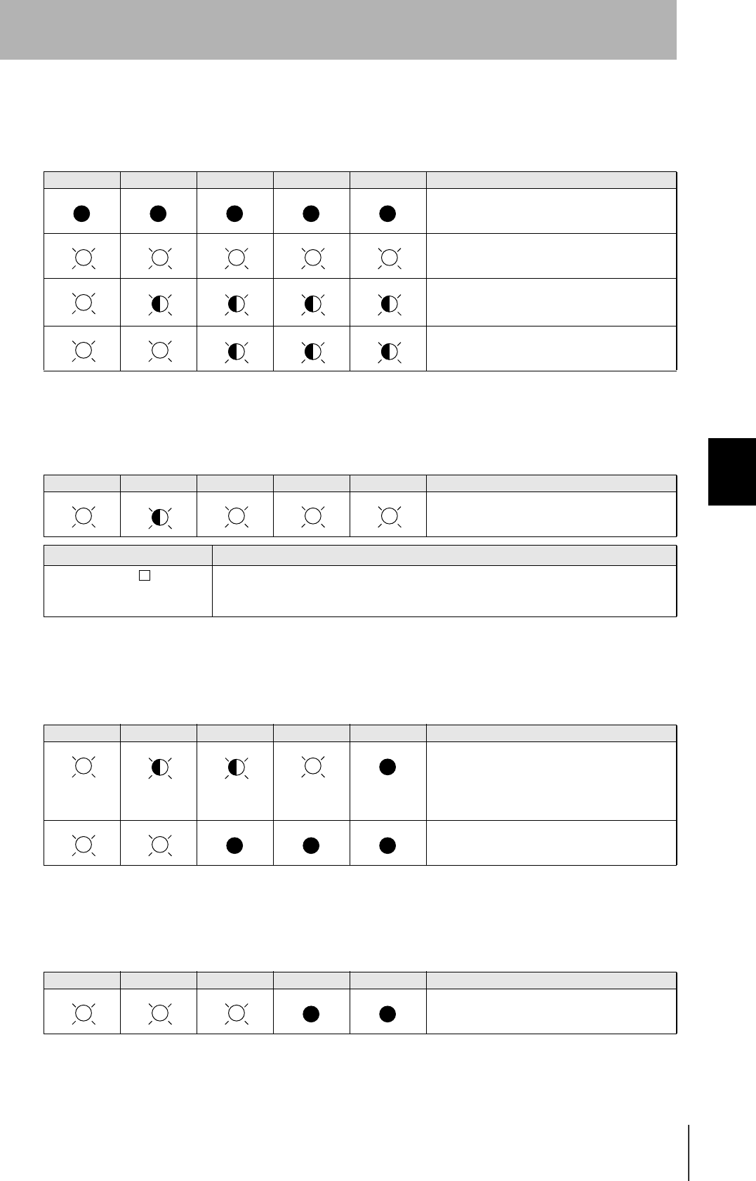
The response messages and response codes (SSACK) in each state are shown below:
State Initializing Operating Maintenance
Message Function IDLE BUSY
S1,F1 OnlineRequest S1,F0 S1,F2 S1,F2 S1,F2
S18,F11 WriteID S18,F0 S18,F0 S18,F0 NO
S18,F7 WriteData S18,F0 NO NO S18,F0
S18,F3 SetAttribute S18,F0 NO NO NO
S18,F13(Reset) Reset S18,F0 NO NO NO
S18,F9 ReadID S18,F0 NO NO NO
S18,F5 ReadData S18,F0 NO NO S18,F0
S18,F13(PerformDiagnostics) Diagnostics S18,F0 NO NO NO
S18,F13(GetStatus) GetStatus S18,F0 NO NO NO
S18,F1 GetAttribute S18,F0 NO NO NO
S18,F13(ChangeState) ChangeState(to MT) S18,F0 NO S18,F0 S18,F0
S18,F13(ChangeState) ChangeState(to OP) S18,F0 S18,F0 S18,F0 NO
S18,F13(ChangeState) ChangeState(to PS) S18,F0 NO S18,F0 NO
74
SECTION 4
When SECS is Not Used
CIDRW System
User’s Manual
SECTION 4
Reading from/Writing to ID Tags
When SECS is Not Used
Command/Response Format
Meaning of FCS (frame check sequence)
This is two ASCII code characters obtained by conversion from the 8-bit exclusive logical sum (EOR) of the characters
from the character immediately after SOH to the character immediately before FCS.
Example: Reading the data of page 1 and page 2 of node No.1:
Command
SOH Node No. Command code Parameter FCS CR
1 ⋅ ⋅ ⋅ n
01h 0Dh
Response
SOH Node No. Response
code
Parameter FCS CR
1 ⋅ ⋅ ⋅ n
01h 0Dh
Command
Calculation range
(ASCII conversion)
75
CIDRW System
User’s Manual
SECTION 4
When SECS is Not Used
SECTION 4
Reading from/Writing to ID Tags
Command
Command code list
Name Value Function See
READ 0100 When this command is received, the system communicates with the ID Tag, and
reads the specified page(s) of data. Any pages up to a maximum of 16 can be
selected.
p.76
WRITE 0200 When this command is received, the system communicates with the ID Tag, and
writes the specified page(s) of data. Any pages up to a maximum of 16 can be
selected.
p.77
Same Write 0300 When this command is received, the system communicates with the ID Tag, and
writes the same data in page units to the specified pages. Up to 17 pages, which is
the maximum number of pages for an ID Tag, can be specified.
p.79
Byte Write 0400 When this command is received the system communicates with the ID Tag, and
writes data to the area specified by a first address and number of bytes. A maximum
of 128 bytes can be specified.
p.80
TEST 10 Sends received data to the host device. p.81
NAK 12 Sends the response made immediately before again. p.82
Noise measurement 40 Measures the noise in the vicinity of the CIDRW Head. p.82
RESET 7F Resets the Amplifier Unit. p.82
Response code list
Type Response
code Name Description
Normal end 00 Normal end Command execution is completed normally.
Host communi-
cations error
14 Format error There is a mistake in the command format.
(E.g. the command code is undefined, or the page or address spec-
ification is inappropriate.)
Communica-
tions error
70 Communications error Noise or another hindrance occurs during communication with an
ID Tag, and communications cannot be completed normally.
71 Verification error Correct data cannot be written to an ID Tag.
72 No Tag error Either there is no ID Tag in front of the CIDRW Head, or the CIDRW
Head is unable to detect the ID Tag due to environmental factors
(e.g. noise).
7B Outside write area error Writing is not completed normally.
7E ID system error (1) The ID Tag is in a status where it cannot execute command pro-
cessing.
7F ID system error (2) An inapplicable ID Tag has been used.
76
SECTION 4
When SECS is Not Used
CIDRW System
User’s Manual
SECTION 4
Reading from/Writing to ID Tags
READ
Reads any pages of data from the ID Tag. The maximum number of pages that can be read at one
time is 16.
Data Segment Area Refer to page 111.
The response code (when normal: 00) and the data in the specified pages are returned in ascending order of
page numbers.
Example: Reading the data of pages 1 and 3 of node No.1
Parameter description
Parameter Description
Page designation Pages are specified by setting the bits corresponding to pages that are to be read to "1" and setting
the other bits to "0", then converting the result to a hexadecimal character string.
SOH Node No. Response
code
Read data
FCS CRPage n ⋅ ⋅ ⋅ Page m (n<m)
Data 1 ⋅ ⋅ ⋅ Data 8 Data 1 ⋅ ⋅ ⋅ Data 8
01h 0 0 0Dh
Data content of the ID Tag
Page 1 12h 34h 56h 78h 90h 12h 34h 56h
Page 2
Page 3 11h 22h 33h 44h 55h 66h 77h 88h
Page 4
Command
Bit 7-07-321076-1076-210
PageSys-SysSys-Sys1716151413-8765-1SysSys
Designation 0* 0* 0* 0* 0* 0/1 0/1 0/1 0/1 0/1 ••• 0/1 0/1 0/1 0/1 ••• 0/1 0* 0*
Value 00 00 - 07 00 - FF 00 - FC
* Always specify 0. If you specify 1 an error (Response code : 14) will occur.
SOH Node No. Command code Page designation (8 characters) FCS CR
01h 0100 0Dh
Response
Command
00000000000000000000000000010100
Binary notation
SOH Node No. Command code Page designation FCS CR
01h01010000000014050Dh
77
CIDRW System
User’s Manual
SECTION 4
When SECS is Not Used
SECTION 4
Reading from/Writing to ID Tags
WRITE
Data is written in page units to the ID Tag. Any page(s) can be specified. It is possible to write to a
maximum of 16 pages at one time.
Data Segment Area Refer to page 111.
The response code (when normal: 00) is returned.
SOH Node No. Response
code Page 1 Page 3 FCS CR
01h 0 1 0 0 123456789012345611223344556677880 70Dh
Parameter description
Parameter Description
Page designation Pages are specified by setting the bits corresponding to pages that are to be read to "1" and setting
the other bits to "0", then converting the result to a hexadecimal character string.
Write data The data to be written to the specified pages is specified in ascending order of page numbers.
SOH Node No. Response
code FCS CR
01h 0 0 0Dh
Response
Command
Bit 7-07-321076-1076-210
PageSys-SysSys-Sys1716151413-8765-1SysSys
Designation 0* 0* 0* 0* 0* 0/1 0/1 0/1 0/1 0/1 ••• 0/1 0/1 0/1 0/1 ••• 0/1 0* 0*
Value 00 00 - 07 00 - FF 00 - FC
* Always specify 0. If you specify 1 an error (Response code : 14) will occur.
SOH Node
No.
Command
code
Page designation
(8 characters)
Write data
FCS CRPage n ⋅ ⋅ ⋅ Page m (n<m)
Data 1 ⋅ ⋅ ⋅ Data 8 Data 1 ⋅ ⋅ ⋅ Data 8
01h 0200 0DH
Response
78
SECTION 4
When SECS is Not Used
CIDRW System
User’s Manual
SECTION 4
Reading from/Writing to ID Tags
Example: Writing data to pages 8 and 10 of node No.1:
The ID Tag status on normal completion is as shown below:
SOH Node No. Response
code FCS CR
01h0100010Dh
Page 8 11h 22h 33h 44h 55h 66h 77h 88h
Page 9
Page 10 01h 23h 45h 67h 89h ABh CDh EFh
Command
00000000000000000000101000000000
SOH Node
No.
Command
code
Page designation Data of page 8 Data of page 10 FCS CR
01h 0 1 0 2 0 000000A0011223344556677880123456789ABCDEF 7 4 0Dh
Binary notation
Response
79
CIDRW System
User’s Manual
SECTION 4
When SECS is Not Used
SECTION 4
Reading from/Writing to ID Tags
Same Write
Writes the same data to multiple pages of an ID Tag.
Any page(s) can be specified.
Data Segment Area Refer to page 111.
The response code (when normal: 00) is returned.
Example: Clearing pages 1 to 17 of node No.1 to 0:
Parameter description
Parameter Description
Page designation Pages are specified by setting the bits corresponding to pages that are to be read to "1" and setting
the other bits to "0", then converting the result to a hexadecimal character string.
Write data Specify the write data.
SOH Node No. Response
code FCS CR
01h 0 0 0Dh
SOH Node No. Response
code FCS CR
01h0100010Dh
Command
SOH Node No. Command code Page designation (8 characters) Write data FCS CR
Data 1 ⋅ ⋅ ⋅ Data 8
01h 0 3 0 0 0DH
Bit 7-07-321076-1076-210
PageSys-SysSys-Sys1716151413-8765-1SysSys
Designation 0* 0* 0* 0* 0* 0/1 0/1 0/1 0/1 0/1 ••• 0/1 0/1 0/1 0/1 ••• 0/1 0* 0*
Value 00 00 - 07 00 - FF 00 - FC
* Always specify 0. If you specify 1 an error (Response code : 14) will occur.
Response
Command
00000000000001111111111111111100
Binary notation
SOH Node No. Command
code Page designation Write data FCS CR
01h 0 1 03000007FFFC0000000000000000 0 0 0Dh
Response
80
SECTION 4
When SECS is Not Used
CIDRW System
User’s Manual
SECTION 4
Reading from/Writing to ID Tags
Byte Write
Writes data to any specified number of bytes starting from the address specified in the ID Tag.
The maximum number of bytes that can be written at one time is 128.
* Data number n = number of bytes written to (2-character units)
Data Segment Area Refer to page 111.
The response code (when normal: 00) is returned.
Example: Writing to two bytes starting from address 05h of node No.1:
The ID Tag status on normal completion is as shown below:
SOH Node No. Command code First
address
Write data FCS CR
Data 1 ••• Data n
01h 0400 0Dh
Parameter description
Parameter Description
Address designation Addresses can be specified in the range 00h to 87h.
Write data Up to 128 bytes of write data, starting from the specified address, can be specified.
SOH Node No. Response
code FCS CR
01h 0 0 0Dh
SOH Node No. Command code First address Write data FCS CR
Data 1 Data 2
01h010400051234040Dh
SOH Node No. Response
code FCS CR
01h0100010Dh
Page 1 12h 34h
Page 2
Command
Response
Command
Response
81
CIDRW System
User’s Manual
SECTION 4
When SECS is Not Used
SECTION 4
Reading from/Writing to ID Tags
TEST
Performs a communication test on communications between the host device and Amplifier Unit.
When an Amplifier Unit receives a test command, it sends the response code and command test data
to the host device as the response.
* Number of data n < 136 (2-character units)
The response code (when normal: 00) and the received test data are returned.
Example: Testing by sending the data "12345678" to node No.1:
SOH Node No. Command code Test data FCS CR
Data 1 ••• Data n
01h 1 0 0Dh
Parameter description
Parameter Description
Test data The data to be sent in the test is specified with a hexadecimal value. (Max. 270 characters)
However, note that odd numbers of characters cannot be used.
SOH Node No. Response
code
Test data FCS CR
Data 1 ••• Data n
01h 0 0 0Dh
SOH Node No. Command code Test data FCS CR
Data 1 Data 2 Data 3 Data 4
01h01 1 0 12345678080Dh
SOH Node No. Response
code
Test data FCS CR
Data 1 Data 2 Data 3 Data 4
01h010012345678090Dh
Command
Response
Command
Response
82
SECTION 4
When SECS is Not Used
CIDRW System
User’s Manual
SECTION 4
Reading from/Writing to ID Tags
NAK
Sends the response made immediately before again.
Sends the response made immediately before again.
Noise measurement
The levels of noise in the vicinity of the CIDRW Head are measured and the noise level is expressed
numerically in the range "00" to "99."
The response code (when normal: 00) and the noise level "00" to "99" are returned.
Influence of background noise on communication distance Refer to page 110.
RESET
All Amplifier Unit processing is stopped, and the initial status is re-established.
There is no response to this command.
SOH Node No. Command code FCS CR
01h 1 2 0Dh
SOH Node No. Command code FCS CR
01h 4 0 0Dh
SOH Node No. Response code Noise level FCS CR
01h 0 0 0Dh
SOH Node No. Command code FCS CR
01h 7 F 0Dh
Command
Response
Command
Response
Command
Response

SECTION 5
Troubleshooting
83
CIDRW System
User’s Manual
SECTION 5
Troubleshooting
When SECS is Used 84
When SECS is Not Used 90
84
SECTION 5
When SECS is Used
CIDRW System
User’s Manual
SECTION 5
Troubleshooting
When SECS is Used
Errors are indicated by the contents of the CIDRW Controller response messages, and by the indicators.
List of Error Messages
When responses are made to messages sent by the CIDRW Controller, errors are expressed by the
contents of error messages and the nature of the SSACK response.
Controller Indicators
If an error or alarm has occurred at the CIDRW Controller, the LEDs on the front of the Controller light.
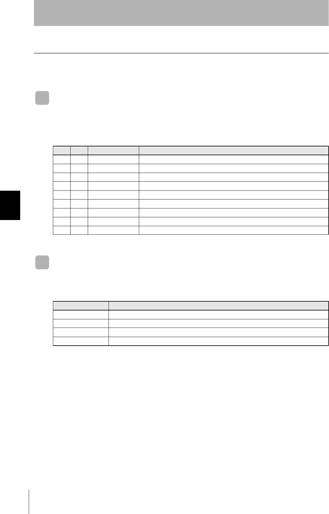
S F Direction SECS II names
10S,H←E Abort Transaction
90S,H→E Abort Transaction
91S,H←E Unrecognized Device ID
93S,H←E Unrecognized Stream Type
95S,H←E Unrecognized Function Type
97S,H←E Illegal Data
99S,H←E Transaction Timer Timeout
911S,H←E Data Too Long
18 0 S,H←E Abort Transaction
Name Function
OPERATING (green) Lit when the operation status (status model) of the CIDRW system is "operating."
ALARMS (green) Lit when the status of "AlamStatus" of the CIDRW system is "Alarm (1)."
BUSY (green) Lit when the status of "OparationalStatus" of the CIDRW system is "BUSY."
ERROR (red) When a processing error is detected (when SSACK is other than "NO"), this indicator is lit for 50 ms.
85
CIDRW System
User’s Manual
SECTION 5
When SECS is Used
SECTION 5
Troubleshooting
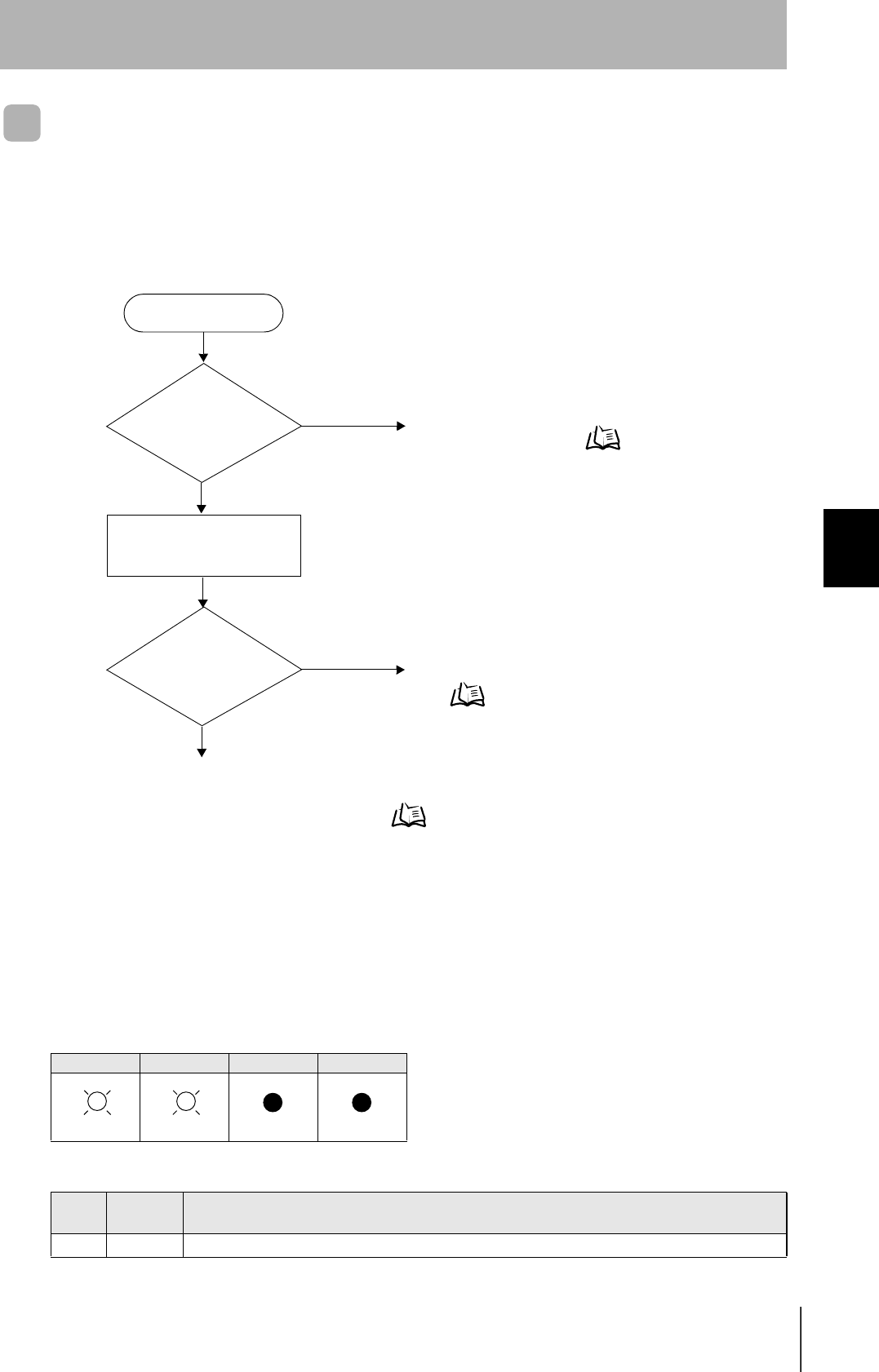
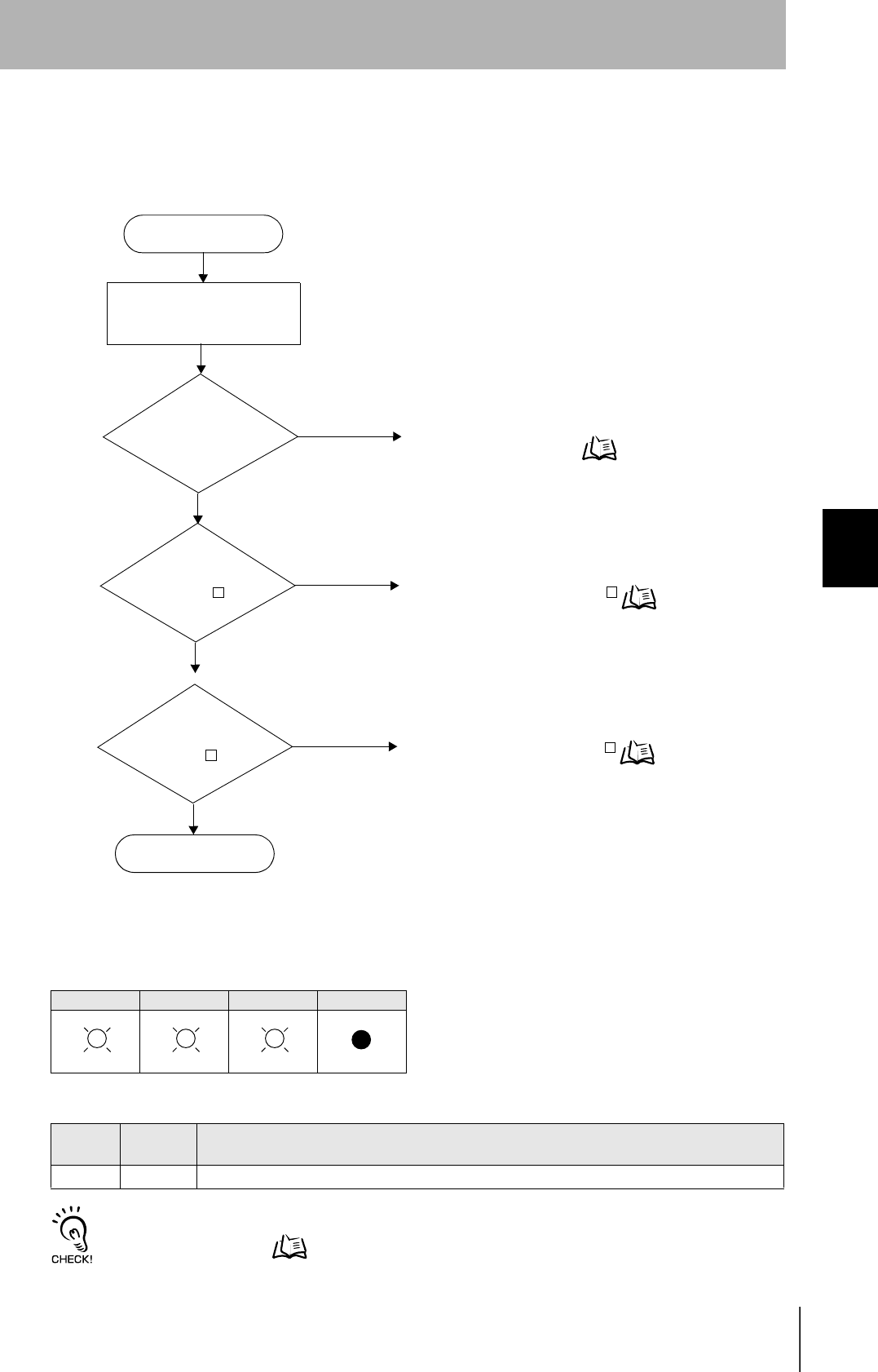
Operation Check Flowchart
Normal Operation Mode
• Operating normally in the Normal Operation mode
Indicators
POWER OPERATING ALARMS BUSY ERROR
Response
Response Function
S F
— — SSACK="NO"
There is a
response to message
transmission.
(SSNAK = other than
"NO")
Error occurrence
All LEDs are lit
or flashing.
POWER-LED is off.
No
Yes
No
Yes
No
An error has occurred in the CIDRW Controller power supply.
Check the power supply of the CIDRW power supply.
Check the contents of the response message.
When the CIDRW Controller responds to a message transmis-
sion Refer to page 86.
Yes An error has occurred at the CIDRW Controller.
Check the status of the indicators.
When all the LEDs are lit or flashing Refer to page 86.
Check if the settings of the CIDRW Controller and Amplifier Unit are correct.
When the CIDRW Controller fails to respond to messages sent to it Refer to page 87.
When an error unrelated to message transmission and responses occurs Refer to page 87.
86
SECTION 5
When SECS is Used
CIDRW System
User’s Manual
SECTION 5
Troubleshooting
• When the CIDRW Controller responds to a message transmission
There is a mistake in the message sent to the CIDRW Controller or the Amplifier Unit settings. After
taking the appropriate corrective action, restart the Controller and the Amplifier Unit and send the mes-
sage again.
• When all the LEDs are lit or flashing
An error has occurred in the CIDRW Controller.
After taking the appropriate corrective action, restart the CIDRW Controller.
Response Main check points
S F
— 0 Status conditions when the message was issued (e.g. a Write ID Request message (S18, F11) was sent in
the operating mode, or the message was sent during initial processing)
Operation Conditions Refer to page 73.
9 7 Message composition: illegal attributes, insufficient items, etc.
Other than
above
Ascertain the cause from the contents of the SSACK response.
CE • Mistake in the details of the items in the message
(The node number of an amplifier that is not set was specified as the "TARGET ID," or a segment
name that is not set has been specified for "DATASEG.")
• Connection of RS-485 cables between Amplifier Units (failure to detect Amplifier Units)
• Amplifier Unit baud rate settings (failure to detect Amplifier Units)
• Node numbers of the Amplifier Units (The same number is set for more than one unit, making
detection impossible)
• Cable routing between the host device and CIDRW Controller (influence of background noise)
• Noise levels of the power supply line to the CIDRW Controller
EE • Installation distance/inclination between the ID Tag and CIDRW Head
• Background noise levels of the CIDRW Head
• Installation spacing in relation to CIDRW Heads connected in other CIDRW systems
HE • Mistake in the details of the items in the message
(A segment that does not match the Amplifier Unit specifications has been set; the response
time-out setting is not correct.)
• Connection and wiring of cable between CIDRW Controller and Amplifier Unit
• Power supply to Amplifier Units
• Amplifier Unit terminal resistance settings
• Routing of each cable (influence of background noise)
• Node numbers of the Amplifier Units (the same number is set for more than one unit)
• Amplifier Unit error (hardware error)
• Noise levels of the power supply line
TE • Type/specifications of the ID Tags used
• Settings of the ID Tags used (lock, etc.)
• Environment of use of the ID Tags (ID Tag breakage due to use in unanticipated ways)
• ID Tag overwrite life
POWER OPERATING ALARMS BUSY ERROR Main check points
• Supply of 24 VDC power
• The CIDRW Controller may be damaged.
• Mode switch setting (Is the setting "0"?)
If the error cannot be resolved after checking,
the CIDRW Controller may be damaged.
• The CIDRW Controller may be damaged.
87
CIDRW System
User’s Manual
SECTION 5
When SECS is Used
SECTION 5
Troubleshooting
• When the CIDRW Controller fails to respond to messages sent to it
There is a mistake in the CIDRW Controller or Amplifier Unit settings.
After taking the appropriate corrective action, restart the CIDRW Controller and Amplifier Unit.
• When an error unrelated to message transmission and responses occurs
There is a mistake in the settings of the CIDRW Controller and Amplifier Unit.
After taking the appropriate corrective action, restart the CIDRW Controller and Amplifier Unit.
POWER OPERATING ALARMS BUSY ERROR Main check points
• Mode switch setting (Is the setting "0"?)
• Cable wiring between the CIDRW Controller
and host device
• Communications conditions for communication
between the CIDRW Controller and host
device (baud rate, character composition, etc.)
• Cable wiring between the CIDRW Controller
and host device
• Node numbers of the Amplifier Units (The
same number is set for more than one unit.)
POWER OPERATING ALARMS BUSY ERROR Main check points
• Mode switch setting (Is the setting "0"?)
• Amplifier Unit baud rate settings
• Node numbers of the Amplifier Units (The
same number is set for more than one unit.)
• Connection and wiring of cable between
CIDRW Controller and Amplifier Unit
• Amplifier Unit error (hardware error)
• Routing of each cable (influence of back-
ground noise)
88
SECTION 5
When SECS is Used
CIDRW System
User’s Manual
SECTION 5
Troubleshooting
Setting Mode
• Operating normally in the Setting mode
Terminal initial screen of the host device after startup in the Setting mode
Terminal screen when parameter setting has been completed without error
Indicators
POWER OPERATING ALARMS BUSY ERROR
Error occurrence
All LEDs are lit
or flashing.
POWER-LED is OFF
No
Yes
No
Yes
An error has occurred in the CIDRW Controller power supply.
Check the power supply of the CIDRW Controller.
An error has occurred at the CIDRW Controller.
Check the status of the indicators.
When all the LEDs are lit or flashing Refer to page 89.
Check if the CIDRW Controller settings are correct.
When the CIDRW Controller fails to respond to messages sent to it Refer to page 89.
When an error unrelated to message transmission and responses occurs Refer to page 89.
SETUP_START <L21 ><XXX.XX, YYY.YY>
_
Software Revision Level
Model number
Hardware Revision Level
SETUP_COMPLETE
_
89
CIDRW System
User’s Manual
SECTION 5
When SECS is Used
SECTION 5
Troubleshooting
• When all the LEDs are lit or flashing
An error has occurred in the CIDRW Controller. After taking appropriate corrective action, restart the
CIDRW Controller and check the indicators.
• When the CIDRW Controller responds to a message transmission
There is a mistake in the CIDRW Controller settings or the sent parameters. After taking appropriate
corrective action, restart the CIDRW Controller and check the indicators.
• When the CIDRW Controller fails to respond to messages sent to it
There is a mistake in the CIDRW Controller settings or the sent parameters. After taking appropriate
corrective action, restart the CIDRW Controller and check the indicators.
• When an error unrelated to message transmission and responses occurs
There is a mistake in the settings of the CIDRW Controller or Amplifier Unit. After taking appropriate
corrective action, restart the CIDRW Controller and Amplifier Unit and check the indicators.
POWER OPERATING ALARMS BUSY ERROR Main check points
• Supply of 24 VDC power
• The CIDRW Controller may be damaged.
• Mode switch setting (Is the setting "3"?)
If the error cannot be resolved after checking,
the CIDRW Controller may be damaged.
• The CIDRW Controller may be damaged.
POWER OPERATING ALARMS BUSY ERROR Main check points
• Sent parameters (Are the parameters cor-
rect? Are the settings correct?)
Response Contents
SETUP_FAILED [ ] The parameters are not updated. The figure in square brackets [ ] indicates the line number
where the error was first detected. If a parity error is detected in the received characters,
this figure is [0].
POWER OPERATING ALARMS BUSY ERROR Main check points
• Transmission parameters (Are the parameters
correct?)
• Communications conditions for communication
between the CIDRW Controller and the host
device (baud rate, character composition, etc.)
• Mode switch setting (Is the setting "3"?)
POWER OPERATING ALARMS BUSY ERROR Main check points
• Mode switch setting (Is the setting "3"?)
90
SECTION 5
When SECS is Not Used
CIDRW System
User’s Manual
SECTION 5
Troubleshooting
When SECS is Not Used
Errors are indicated by the presence or absence of a response to an Amplifier Unit command, and by the
indicators.
List of Error Messages
Amplifier Unit Indicators
Type Response
code Name Description
Host communi-
cations error
14 Format error There is a mistake in the command format.
(E.g. the command portion is undefined, or the page or address speci-
fication is inappropriate.)
Communications
error between
the CIDRW Head
and ID Tag
70 Communications
error
Noise or another hindrance has occurred during communication with
an ID Tag, and communications cannot be completed normally.
71 Verification error Correct data cannot be written to an ID Tag.
72 No Tag error Either there is no ID Tag in front of the CIDRW Head, or the CIDRW
Head is unable to detect the ID Tag due to environmental factors (e.g.
noise).
7B Outside write area
error
The ID Tag is at a position where reading is possible but writing is not,
so writing does not complete normally.
7E ID system error (1) The ID Tag is in a status where it cannot execute the command pro-
cessing.
7F ID system error (2) An inapplicable ID Tag has been used.
Name Indications
RUN (green) Turns ON when the Amplifier Unit is in normal operation.
COMM (orange) Turns ON during communications with the host device or during communications with an ID Tag.
NORM (green) Turns On when the communications finish with no error.
ERROR (red) Turns ON when an error occurs during communication with the host device, or during communication with
an ID Tag.
91
CIDRW System
User’s Manual
SECTION 5
When SECS is Not Used
SECTION 5
Troubleshooting
Operation Check Flowchart
From Installation to Trial Operation
Errors are indicated by whether or not a response to the test command is received and by the status of
the Amplifier Unit indicators.
• If the test command was received normally:
Indicators
RUN COMM NORM ERROR
Response code for the response
Type Response
code Function
Normal 00 The command was received normally.
Error occurrence
Test command transmission
RUN-LED is OFF
No
Yes An error has occurred at the Amplifier Unit.
Amplifier Unit error Refer to page 92.
Check if the Amplifier Unit settings are correct.
If there is no response to the command: Refer to page 92.
Response received Yes Check the nature of the response.
If there is a response to the command
Refer to page 92.
No
(Lights once)
92
SECTION 5
When SECS is Not Used
CIDRW System
User’s Manual
SECTION 5
Troubleshooting
• Amplifier Unit error
Check the status of the indicator LEDs after transmission of the test command.
After taking appropriate corrective action, restart the Amplifier Unit, send the test command again and
check again.
• If there is no response to the command:
Check the status of the indicator LEDs after transmission of the test command.
After taking appropriate corrective action, restart the Amplifier Unit, send the test command again and
check again.
Method using RS signal control at the host device
In a 1:N connection using Link Units, the RS signals generated from the host device by normal control must be input as
CS signals. Turn the RS signals OFF within 15 ms after the completion of data transmission. Correct communications
will not be possible without this control.
• If there is a response to the command:
Check the status of the indicator LEDs after transmission of the test command.
After taking appropriate corrective action, restart the Amplifier Unit, send the test command again and
check again.
RUN COMM NORM ERROR Main check points
—
(If RUN is OFF, the status of the other indica-
tor LEDs can be ignored.)
• Influence of background noise (change installation position)
• Amplifier Unit power supply
If the error cannot be resolved after checking, the Amplifier Unit
may be damaged.
RUN COMM NORM ERROR Main check points
• Amplifier Unit baud rate settings
• Node numbers of the Amplifier Units (do not match the node
number in the test command)
• Connection and wiring of the cable between the host device
and Amplifier Unit
• OFF timing of the RS signals between the host device and
Amplifier Unit
• Routing of each cable (influence of background noise)
If the error cannot be resolved after checking, the Amplifier Unit
may be damaged.
• Amplifier Unit baud rate settings
• Connection and wiring of the cable between the host device
and Amplifier Unit
• Routing of the cables (influence of background noise)
• OFF timing of the RS signals between the host device and
Amplifier Unit
• FCS (frame check sequence) calculation method
RUN COMM NORM ERROR Main check points
• Node numbers of the Amplifier Units (The same number is set
for more than one unit)
If the error cannot be resolved after checking, the Amplifier
Unit may be damaged.
There is a mistake in the command format (number of charac-
ters, character code, etc.).
(Lights once)
SD at host device
RS at host device
ON only during data transmission from the host device
Within 15 ms
(Lights once)
93
CIDRW System
User’s Manual
SECTION 5
When SECS is Not Used
SECTION 5
Troubleshooting
From Trial Operation to Communications
Errors are indicated by the status of the indicators after transmission of the write command, and by the
response code of the response.
• If the ID Tag was processed normally:
If there is no response to the write command, refer to the From Installation to Trial Operation,
Operation Check Flowchart. Refer to page 91.
Indicators
RUN COMM NORM ERROR
Response code for the response
Type Response
code Function
Normal 00 The ID Tag was processed normally.
Error occurrence
Is the response
code 1 ?
No
Yes Check the command format.
If the response code is 1 Refer to page 94.
Yes Communication with the ID Tag has failed.
If the response code is 7 Refer to page 94.
Write command sent
RUN-LED is OFF
No
Yes An error has occurred at the Amplifier Unit.
Amplifier Unit error Refer to page 94.
Is the response
code 7 ?
Communications OK
No
(Lights once) (Lights once)
94
SECTION 5
When SECS is Not Used
CIDRW System
User’s Manual
SECTION 5
Troubleshooting
• Amplifier Unit error
Check the status of the indicator LEDs after transmission of the command.
After taking appropriate corrective action, send the write command again and check again.
• If the response code is 1 :
There is a host device communications error.
Check the status of the indicator LEDs and the response code of the response after transmission of the
command.
After taking appropriate corrective action, send the write command again and check again.
• If the response code is 7 :
There is a communications error in communication between the CIDRW Head and ID Tag.
Check the status of the indicator LEDs and the response code of the response after transmission of the
command.
After taking appropriate corrective action, send the write command again and check again.
* The ID Tag has a lock function, but the amplifier unit has no function for locking an ID Tag.
RUN COMM NORM ERROR Main check points
—
(If RUN is OFF, the status of the other indica-
tor LEDs can be ignored.)
• Influence of background noise (Change installation position)
• Amplifier Unit power supply
If the error cannot be resolved by checking the two points above,
the Amplifier Unit may be damaged.
RUN COMM NORM ERROR
Response
code Main check points
14 Command format
(Command code, page designation, address designation, processed data volume, etc.)
RUN COMM NORM ERROR
Response
code Main check points
70
• Background noise levels of the CIDRW Head (Check the surroundings with the environmental noise level measurement
function)
• Distance to another CIDRW Head
• Influence of background noise (Change installation position)
If the error cannot be resolved after checking, the Amplifier Unit may be damaged.
71 • ID Tag overwrite life (Replace the ID Tag)
• Environment of use of the ID Tags (ID Tag breakage due to use in unanticipated ways)
72 • Connection to the CIDRW Head
• Distance between the ID Tag and CIDRW Head
• CIDRW Head background noise levels (Check the surroundings with the environmental noise level measurement function)
• Distance to another CIDRW Head
7B • Distance between the ID Tag and CIDRW Head
• Background noise levels of the CIDRW Head (Check the surroundings with the environmental noise level measurement
function)
• Distance to another CIDRW Head
• Influence of background noise (Change installation position)
7E • Type/specifications of the ID Tags used
• Settings of the ID Tags used (The ID Tag lock function is used.*)
• Environment of use of the ID Tags (ID Tag breakage due to use in unanticipated ways)
7F
(Lights once)
(Lights once) (Lights once)

SECTION 6
Appendix
95
CIDRW System
User’s Manual
SECTION 6
Appendix
Specifications and Dimensions 96
System Configuration Examples 100
When SECS is Not Used 101
Data Segment Area 111
Regular Inspection 112
SECS Protocol Specifications 113
ASCII Code Table 118
Protective Construction 119
96
SECTION 6
Specifications and Dimensions
CIDRW System
User’s Manual
SECTION 6
Appendix
Specifications and Dimensions
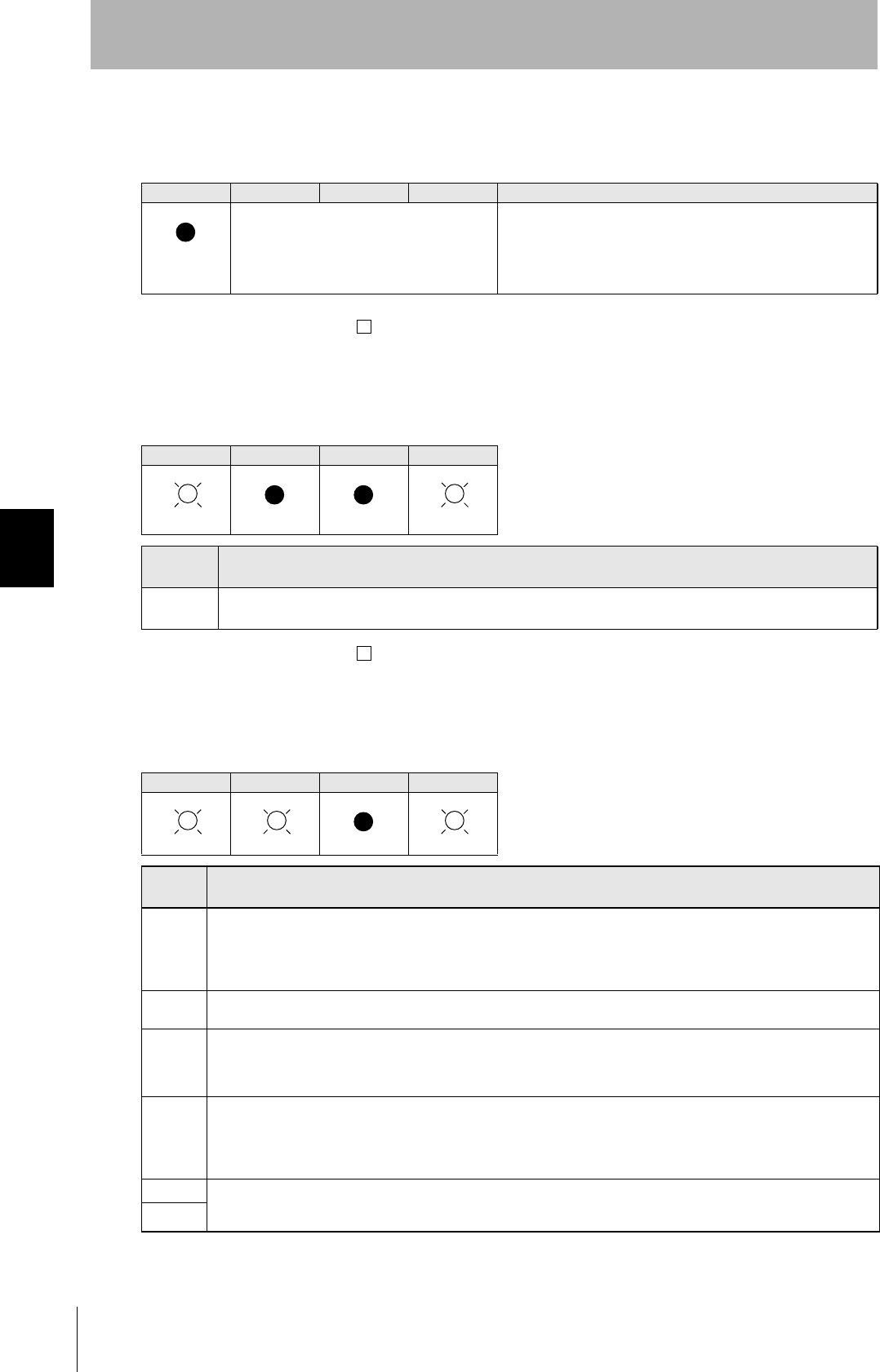
Controller
V700-L21
Item Specifications
Power supply voltage 24 VDC +10% -15%
Current consumption 150 mA max. (inrush current: approx. 10 A max.)
Ambient temperature Operating: 0 to +40°C Storage: -15 to +65°C (with no icing)
Ambient humidity Operating: 10 to 85% RH Storage: 10 to 95% RH (with no condensation)
Degree of protection IP20 (IEC60529)
Insulation resistance 50 MΩ min. between power supply terminals and the frame ground terminal (500 VDC M)
Dielectric strength Leak current not to exceed 3.5 mA on application of 500 VAC (50/60 Hz for 1 minute) between both
power supply terminals and the frame ground terminal
Vibration resistance Frequency: 10 to 150 Hz; double amplitude: 0.20 mm; acceleration: 15 m/s2 for
8 minutes, 10 times each in X, Y, and Z directions
Shock resistance Shock of 150 m/s2 in X, Y, and Z directions, 3 times each for 18 repetitions
Ground Ground to 100 Ω or less.
Case material SECC (coating)
Weight Approx. 570 g
2:
r
r
/
Ǿ
(Unit: mm)
Mounting dimensions
Power indicator
Indicators
(mounting holes)
Four, 4.5-dia. holes
CIDRW System
User’s Manual
SECTION 6
Specifications and Dimensions
SECTION 6
Appendix
97
Amplifier Unit
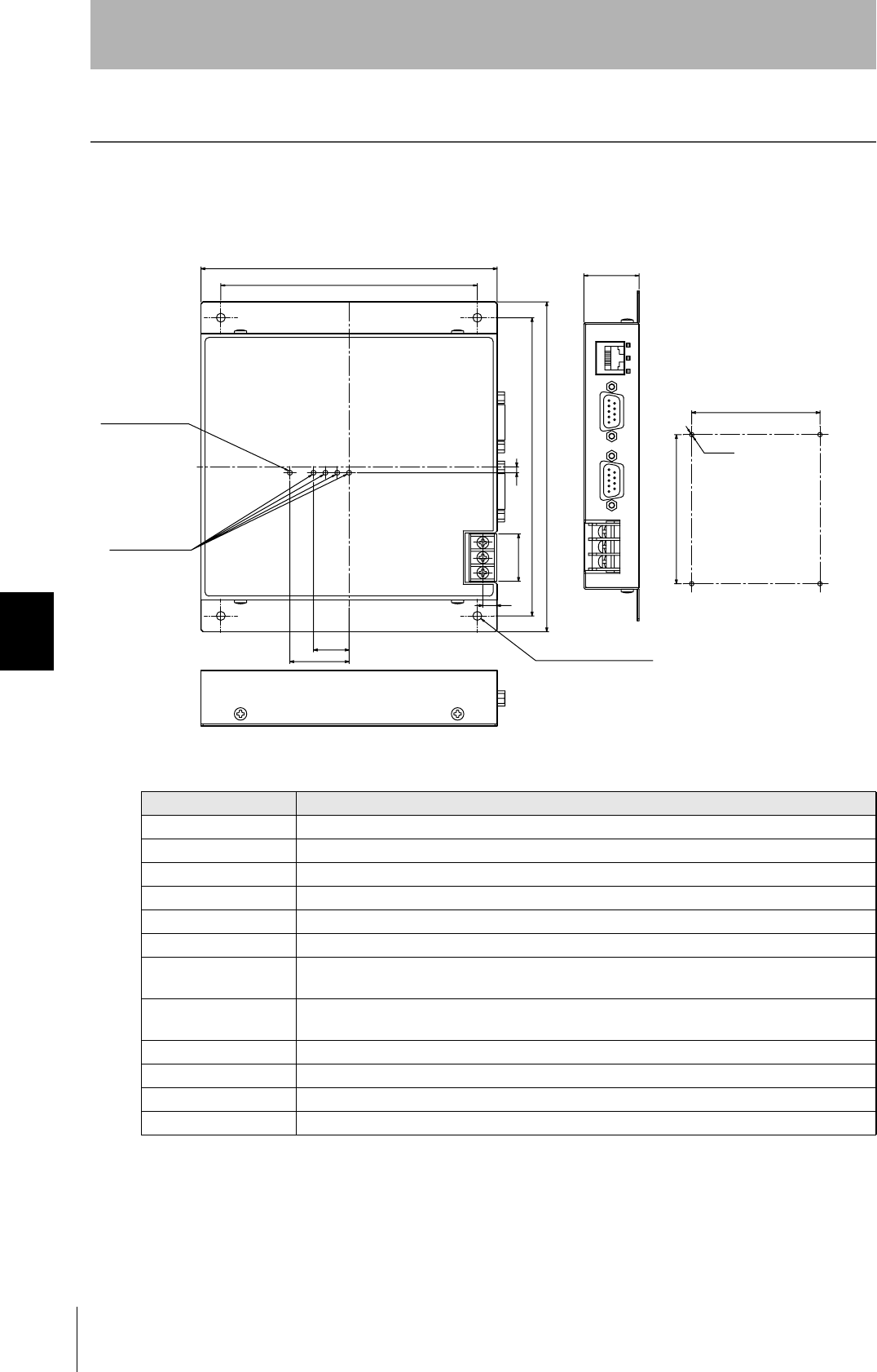
V640-HAM11
Item Specifications
Power supply voltage 24 VDC +10% -15%
Current consumption 150 mA max.
Ambient temperature Operating: 0 to +40°C Storage: -15 to +65°C (with no icing)
Ambient humidity Operating/Storage: 35 to 85% RH (with no condensation)
Degree of protection IP20 (IEC60529 standard)
Insulation resistance 20 MΩ min. between power supply terminals and the frame ground terminal (100 VDC M)
Dielectric strength Leak current not to exceed 5 mA on application of 1000 VAC (50/60 Hz for 1 minute) between both
power supply terminals and the frame ground terminal
Vibration resistance Frequency: 10 to 150 Hz; double amplitude: 0.20 mm; acceleration: 15 m/s2 for
8 minutes, 10 times each in X, Y, and Z directions
Shock resistance Shock of 150 m/s2 in X, Y, and Z directions, 3 times each for 18 repetitions
Ground Ground to 100 Ω or less.
Case material SECC (coating)
Weight Approx. 500 g
㧔㧕
㧔㧕
㧔㧕
㧔㧕
㧔㧕
㧔㧕
㧔㧕
㧔㧕
㧔㧕
r
r
Ǿ
/
DIP switch
(Unit: mm)
Mounting dimensions
4 indicators
Four, 4.5-dia. holes
98
SECTION 6
Specifications and Dimensions
CIDRW System
User’s Manual
SECTION 6
Appendix
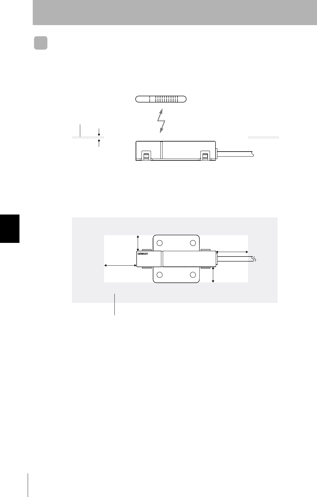
CIDRW Head
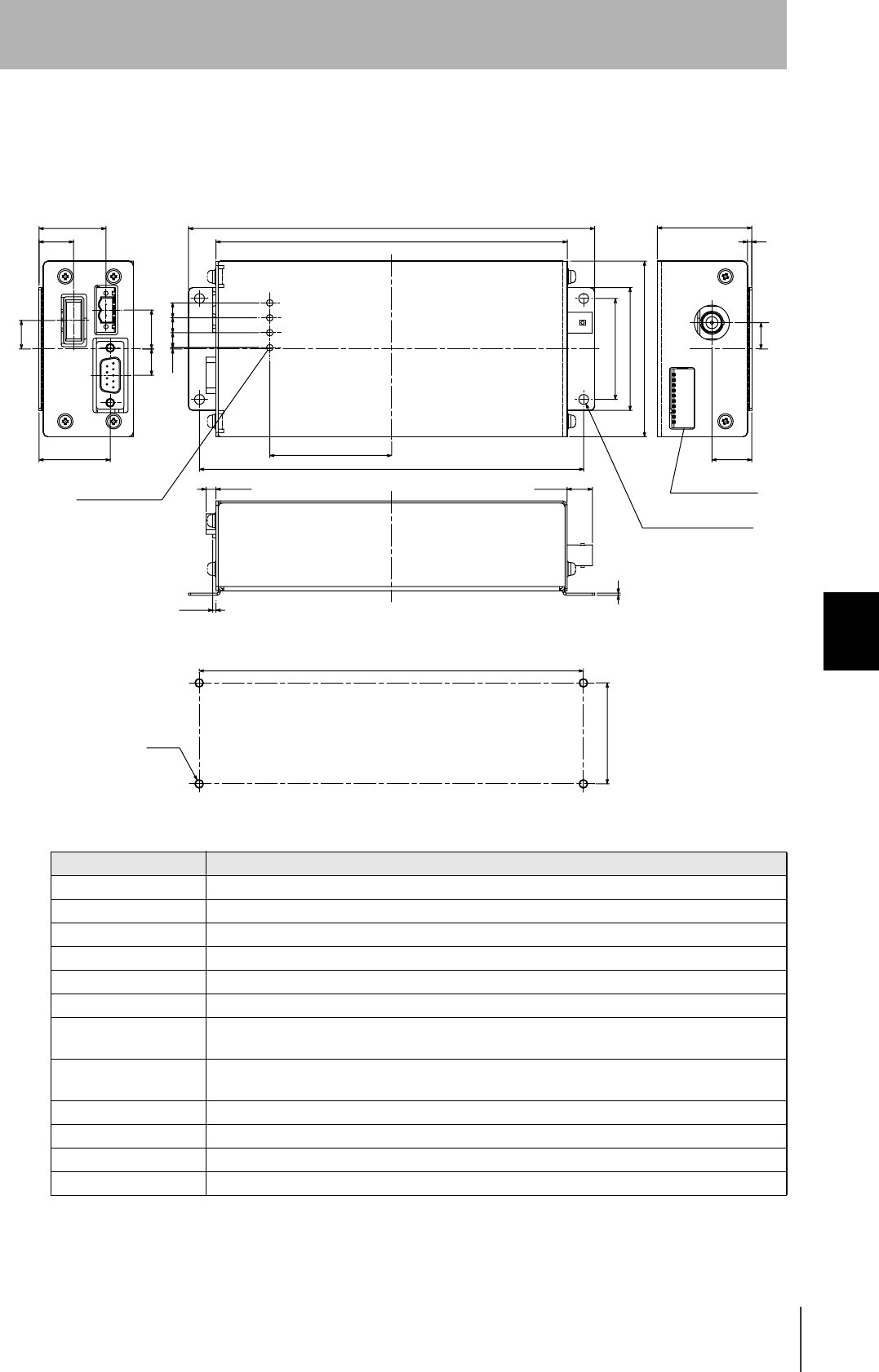
V640-HS61
Item Specifications
Transmission frequency 134 kHz
Ambient temperature Operating: 0 to +40°C Storage: -15 to +65°C (with no icing)
Ambient humidity Operating/Storage: 35 to 85% RH (with no condensation)
Degree of protection IP60 (IEC60529)
Insulation resistance 20 MΩ min. between all terminals and the case (100 VDC M)
Dielectric strength Leak current not to exceed 5 mA on application of 1000 VAC (50/60 Hz for 1 minute) between all
terminals and the case
Vibration resistance Frequency: 10 to 150 Hz; double amplitude: 0.20 mm; acceleration: 15 m/s2 for
8 minutes, 10 times each in X, Y, and Z directions
Shock resistance Shock of 150 m/s2 in X, Y, and Z directions, 3 times each for 18 repetitions
Casing material ABS/epoxy resin
Stainless steel mount
Weight Approx. 70 g
Cable length 2 m
Cable specification 3-mm-dia. coaxial cable (no flexibility)
r
r
Ǿ
/14Ǿ
Coaxial cable 3.0 dia., standard length 2 m
(Unit: mm)
Connector
Antenna center
Antenna center
Mounting dimensions
Four M3 or 3.5-dia. holes
Four, 3.5-dia. holes
CIDRW System
User’s Manual
SECTION 6
Specifications and Dimensions
SECTION 6
Appendix
99
Link Unit
V700-L11
Item Specifications
Power supply voltage 24 VDC +10% -15%
Current consumption 250 mA max. (inrush current: approx. 10 A)
Ambient temperature Operating: 0 to +40°C Storage: -15 to +50°C (with no icing)
Ambient humidity Operating/Storage: 35 to 85% RH (with no condensation)
Degree of protection IP20 (IEC60529)
Insulation resistance 50 MΩ min. between power supply terminals and the frame ground terminal (500 VDC M)
Dielectric strength Leak current not to exceed 5 mA on application of 1000 VAC (50/60 Hz for 1 minute) between
power supply terminals and the frame ground terminal
Vibration resistance Frequency: 10 to 150 Hz; double amplitude: 0.20 mm; acceleration: 15 m/s2 for 8 minutes, 10 times
each in X, Y, and Z directions
Shock resistance Shock of 150 m/s2 in X, Y, and Z directions, 3 times each for 18 repetitions
Ground Ground to 100 Ω or less.
Case material PC/ABS resin
Weight Approx. 200 g
r
r
Ǿ
/ޓ14ޓǾ
(Unit: mm)
Mounting dimensions
Two M4 or 4.2-dia. holes
Two, 4.5-dia. holes
100
SECTION 6
System Configuration Examples
CIDRW System
User’s Manual
SECTION 6
Appendix
System Configuration Examples
When SECS is Used
Communication with the host device is possible using the SECS protocol.
Using Link Units to make connections makes it possible to remove and replace just the relevant Ampli-
fier Unit while leaving the power to the CIDRW system on in the event of a failure or during mainte-
nance.
Host
These are antennae for
reading the carrier IDs
from the ID Tags and
writing the carrier IDs.
These are units that
control a CIDRW Head.
Up to 31 units can be
connected.
This is e.g. a host,
or equipment con-
troller.
CIDRW Head
V640-HS61
Amplifier Unit
V640-HAM11
CIDRW Controller
V700-L21
Multiple Amplifier Units
are controlled in
response to commands
(SECS) from the host
device.
RS-232C
SECS I/II
Max. 50 m
RS-485
RS-232C
SECS I/II
RS-232C
Link unit
V700-L11
Just the relevant Amplifier Unit can be
removed and replaced while the power
remains on.
Max. 50 m
RS-485
Up to 31 units can be connected.
CIDRW System
User’s Manual
SECTION 6
System Configuration Examples
SECTION 6
Appendix
101
When SECS is Not Used
Communications with the host device follow the OMRON proprietary protocol.
The Amplifier Units are connected directly to the host device without using a CIDRW Controller.
Using Link Units to make connections makes it possible to remove and replace just the relevant Ampli-
fier Unit while leaving the power to the CIDRW system on in the event of a failure or during mainte-
nance.
Host
These are antennae for
reading the carrier IDs
from the ID Tags and
writing the carrier IDs.
These are units that
control a CIDRW Head.
Up to 31 units can be
connected.
This is e.g. a host,
or equipment con-
troller.
Amplifier Unit
V640-HAM11
RS-232C
OMRON original protocol
Max. 50 m
CIDRW Head
V640-HS61
Max. 50 m
Link unit
V700-L11
Just the relevant Amplifier Unit can be
removed and replaced while the power
remains on.
RS-485
Up to 31 units can be connected.
RS-232C
OMRON original protocol
102
SECTION 6
Characteristic Data depending on Conditions of Use
CIDRW System
User’s Manual
SECTION 6
Appendix
Characteristic Data depending on Conditions of Use
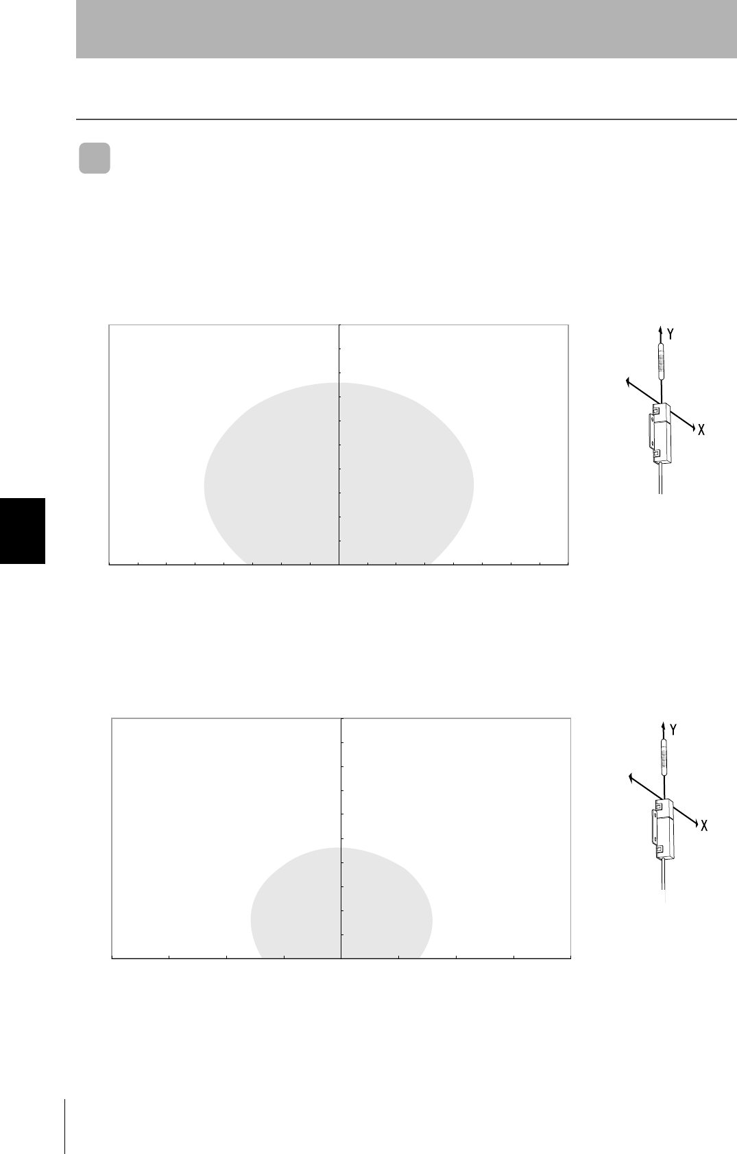
Maps of Communications Areas (Reference Only)
Coaxial Mounting
• READ
•WRITE
Communications Areas (READ)
Distance in Y direction (mm)
Distance in X direction (mm)
Communications Areas (WRITE)
Distance in Y direction (mm)
Distance in X direction (mm)
CIDRW System
User’s Manual
SECTION 6
Characteristic Data depending on Conditions of Use
SECTION 6
Appendix
103
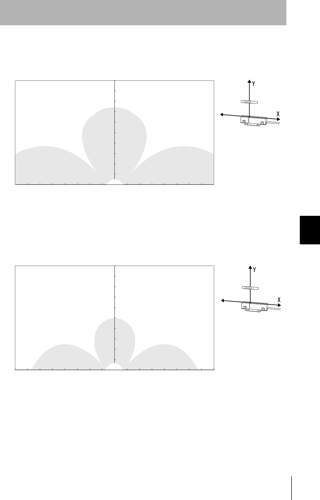
Parallel Mounting
• READ
•WRITE
Communications Areas (READ)
Distance in Y direction (mm)
Distance in X direction (mm)
0
Communications Areas (WRITE)
Distance in Y direction (mm)
Distance in X direction (mm)
0
104
SECTION 6
Characteristic Data depending on Conditions of Use
CIDRW System
User’s Manual
SECTION 6
Appendix
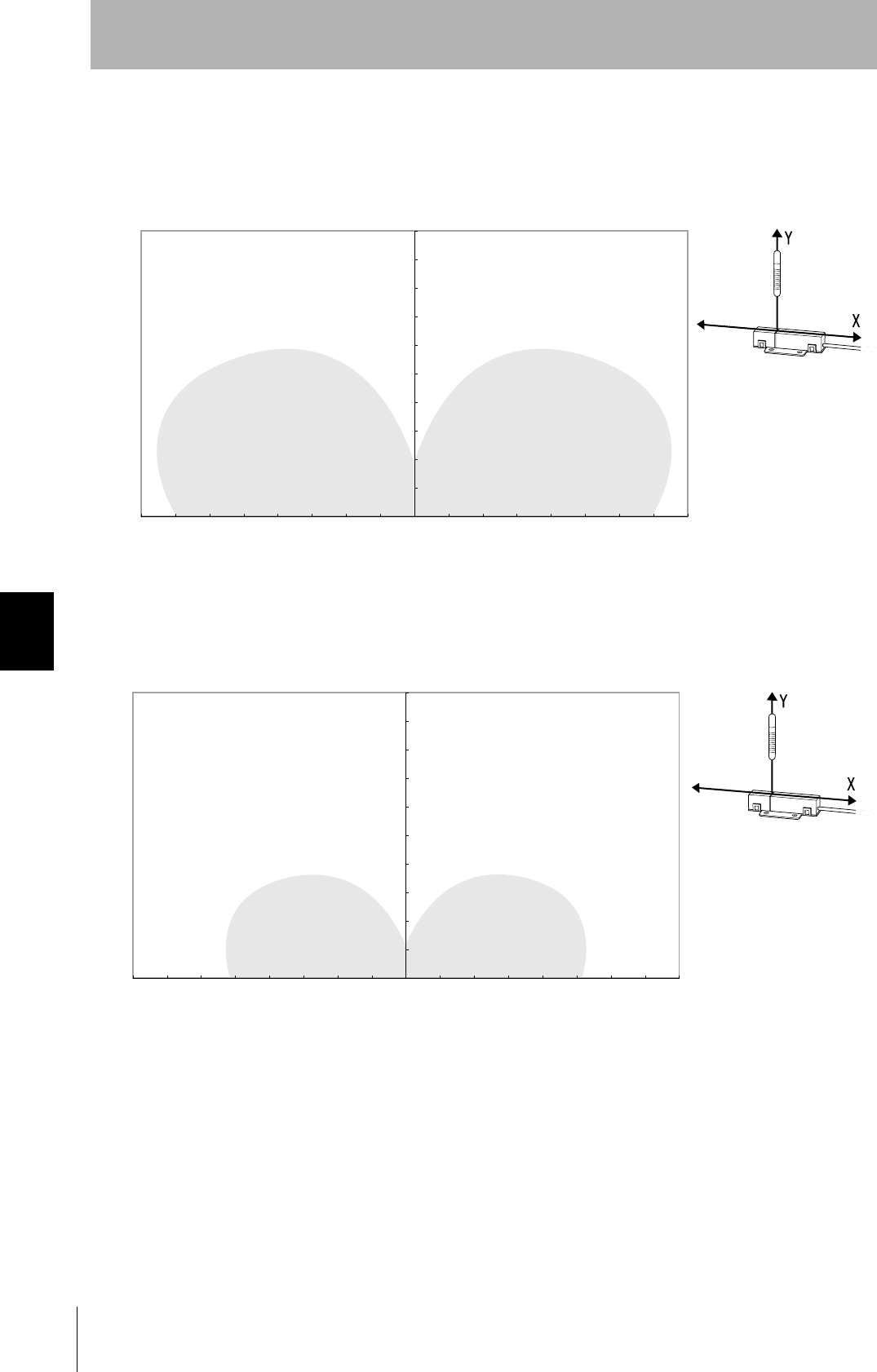
Vertical Mounting
• READ
•WRITE
Communications Areas (READ)
Distance in Y direction (mm)
Distance in X direction (mm)
Communications Areas (WRITE)
Distance in Y direction (mm)
Distance in X direction (mm)
CIDRW System
User’s Manual
SECTION 6
Characteristic Data depending on Conditions of Use
SECTION 6
Appendix
105
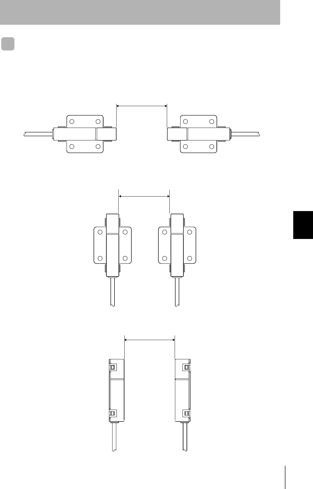
Mutual Interference Distances (Reference Only)
In order to prevent malfunction due to mutual interference when multiple CIDRW Heads are used,
install the heads with the spacing indicated below.
For Coaxial Installation:
For Parallel Installation:
For Face-to-Face Installation:
1 m min.
1 m min.
1 m min.
106
SECTION 6
Characteristic Data depending on Conditions of Use
CIDRW System
User’s Manual
SECTION 6
Appendix
Influence of Background Metals (Reference Only)
The CIDRW Head can also communicate from an opening in a ceiling panel (metal body).
However, ensure the distances indicated below between the CIDRW Head and the metal body. If you
do not ensure these distances the communications distance will be substantially shortened.
Metal body (material: AL, SUS)
(Thickness : 1 mm)
8*5
%+&49*'#&
10 mm min.
10 mm min.
20 mm min.
20 mm min.
Metal body (material: AL, SUS)
CIDRW System
User’s Manual
SECTION 6
Characteristic Data depending on Conditions of Use
SECTION 6
Appendix
107
Communications Time
Regardless of whether SECS is used or not, take the time required for processing between the host
device and Amplifier Units into account when designing the system.
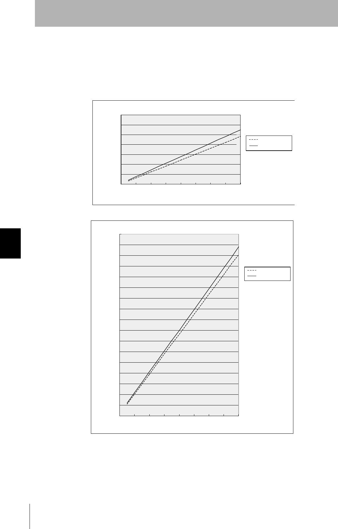
Communication time calculation formula (unit: ms)
Read: 150.5 × (number of pages) + 6.1
For write, same writing: 468.6 × (number of pages) + 80.3
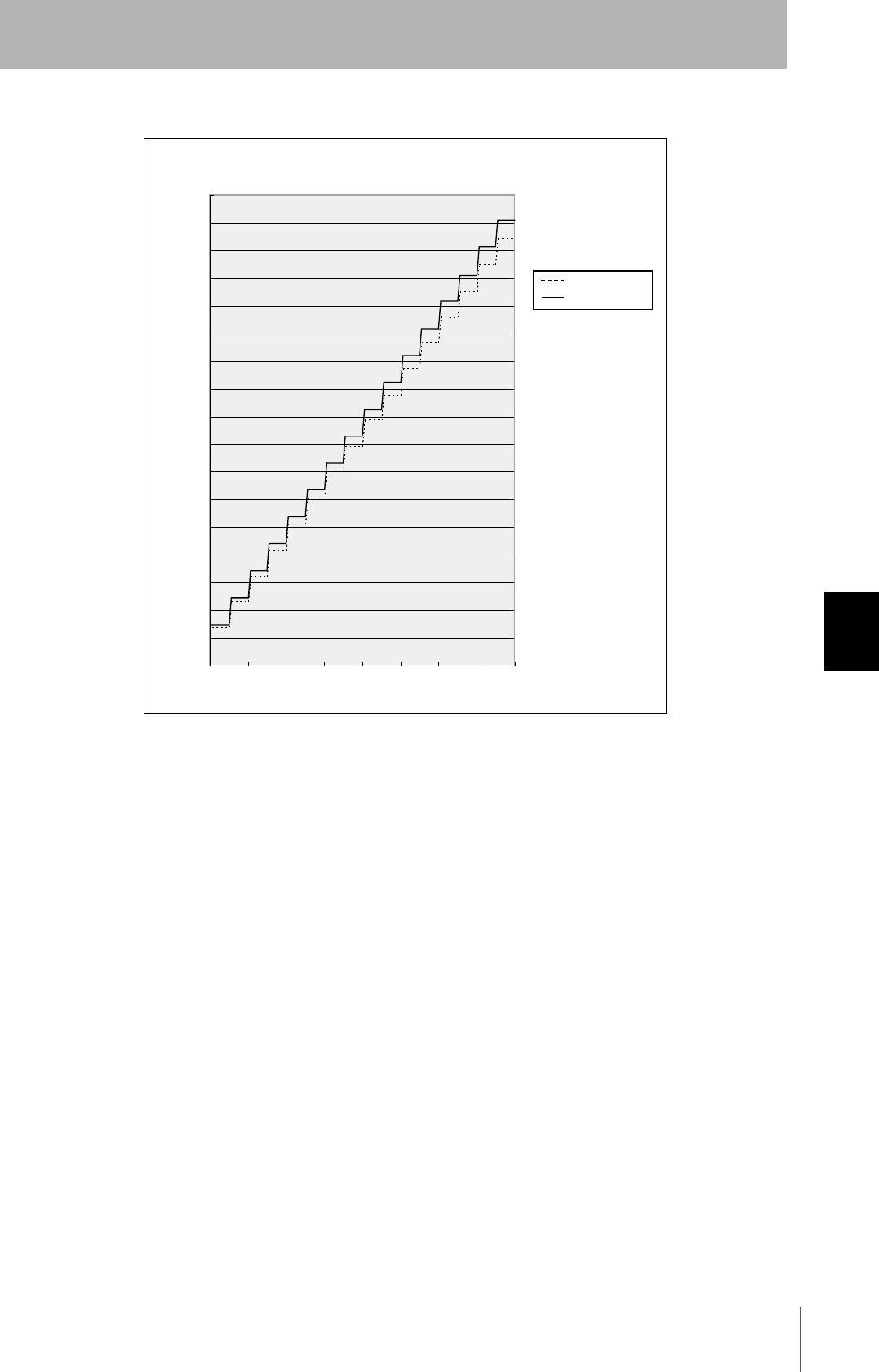
Byte write: 468.6 × (number of pages/8) + 229.9
TAT calculation formula (units: ms)
TAT = command and response transmission time + communication time
The command and response transmission time differs depending on the number of characters
sent and the communications conditions.
This calculation applies to continuous transmission in which the Controller uses no spaces
between command characters.
Example of TAT calculation:
Number of command characters: A; number of response characters: B
Baud rate: 9600 bps, data length: 8 bits, non parity, 1 stop bit
Time Description
Communications time This is the time required for communication between an ID Tag and the CIDRW Head.
TAT This is the time required for processing at the Amplifier Unit, seen from the host device.
Host
Amplifier Unit
Command Response
Communications time
TAT
Rounding up
Transmission time (ms) = Number of bits per character (bits)
Baud rate (bps) × total number of characters of command and response
TAT (ms) = 10
9600 × (A + B) + Communications time (ms)
108
SECTION 6
Characteristic Data depending on Conditions of Use
CIDRW System
User’s Manual
SECTION 6
Appendix
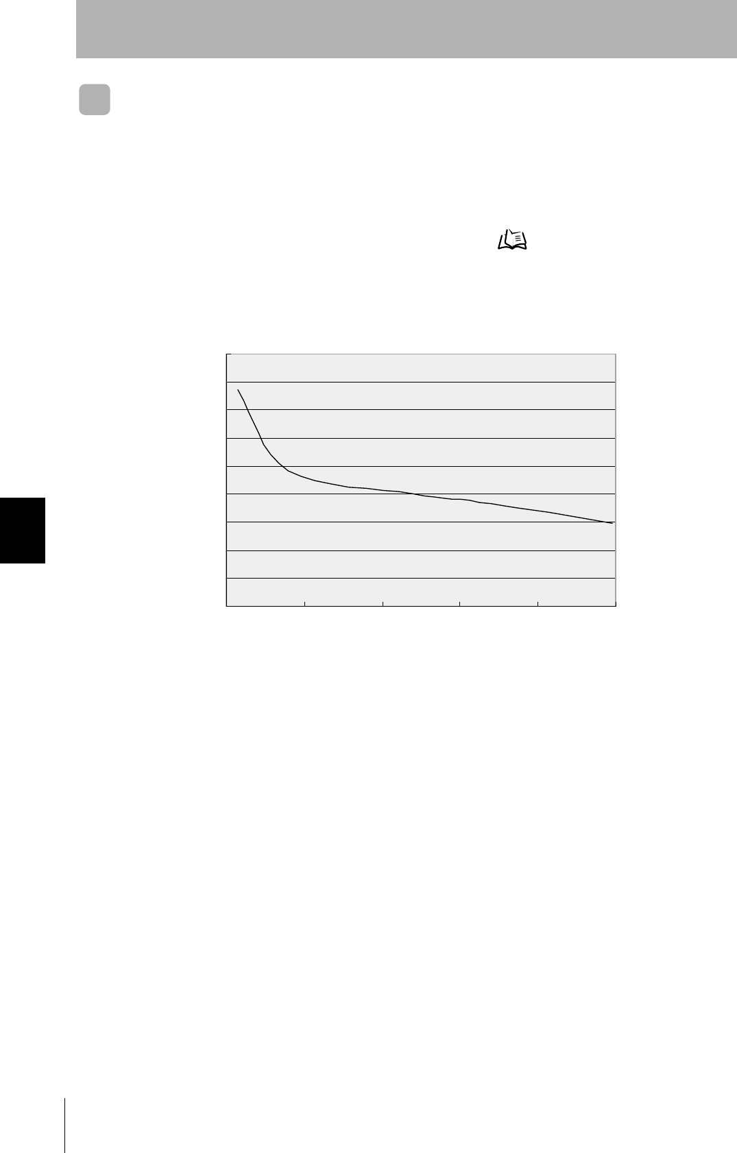
The graph for communications time for communication between the ID Tag and CIDRW Head, and
TAT (when the baud rate is 9600 bps), is shown below.
Note however that the communications time and TAT may increase substantially according to the con-
ditions of use.
㪇
㪌㪇㪇
㪈㪇㪇㪇
㪈㪌㪇㪇
㪉㪇㪇㪇
㪉㪌㪇㪇
㪊㪇㪇㪇
㪊㪌㪇㪇
㪈㪉㪋㪍㪏㪈㪇㪈㪉㪈㪋㪈㪍
Read
Number of pages processed
Communications time
TAT (9600 bps)
Communications time (ms)
Communications time (ms)
Write (same writing)
Number of pages processed
Communications time
TAT (9600 bps)
CIDRW System
User’s Manual
SECTION 6
Characteristic Data depending on Conditions of Use
SECTION 6
Appendix
109
Communications time (ms)
Byte Write
Number of bytes processed
Communications time
TAT (9600 bps)
110
SECTION 6
Characteristic Data depending on Conditions of Use
CIDRW System
User’s Manual
SECTION 6
Appendix
Communications Distance Characteristics vs. Ambient Noise
The graph below compares the results of measurement using the noise measurement function with
communications distances.
At installation implement measures in regard to metal in the vicinity of the CIDRW Head, power supply
noise, and atmospheric noise, to ensure that the noise level does not exceed "10."
Noise measurement command (applies only when SECS is not used) Refer to page 82.
ᦨ
ᄢ୯
Noise level
Communications distance (mm)
Relationship between noise level and communications distance (reference values)
(Max.)
CIDRW System
User’s Manual
SECTION 6
Data Segment Area
SECTION 6
Appendix
111
Data Segment Area
The data segment area of the RI-TRP-DR2B ID Tag is shown below.
When using a CIDRW Controller, always set the data segment.
Refer to page 48.
• The carrier ID memory area starts from page 1 (fixed).
• 00h to 87h in the table are addresses.
Page 8 bytes/1 page
1 00h 01h 02h 03h 04h 05h 06h 07h
2 08h 09h 0Ah 0Bh 0Ch 0Dh 0Eh 0Fh
3 10h 11h 12h 13h 14h 15h 16h 17h
4 18h 19h 1Ah 1Bh 1Ch 1Dh 1Eh 1Fh
5 20h 21h ••• ••• 27h
6 28h 29h ••• ••• 2Fh
7 30h 31h ••• ••• 37h
8
9 :
10 : :
11 :
12
13
14 68h 69h ••• ••• 6Fh
15 70h 71h ••• ••• 77h
16 78h 79h ••• ••• 7Fh
17 80h 81h ••• ••• 87h
DATASEG LENGTH
Carrier
ID
16
"S01" 8
"S02" 8
"S03" 8
"S04" 8
"S05" 8
"S06" 8
"S07" 8
"S08" 8
"S09" 8
"S10" 8
"S11" 8
"S12" 8
"S13" 8
"S14" 8
"S15" 8
Carrier ID
(16 byte)
Data area
(Total of 120
bytes)
Data segment area Example of data
segment settings

112
SECTION 6
Regular Inspection
CIDRW System
User’s Manual
SECTION 6
Appendix
Regular Inspection
In order to maintain optimum performance of the functions of the CIDRW system, daily and periodic
inspections are necessary.
Inspection item Detail Criteria Tools required
Supply voltage fluctuation Check that the supply voltage fluctuation
at the power supply terminal block is
within the permissible range.
To be within supply voltage rating. Multimeter
Check that there are no frequent instan-
taneous power failures or radical voltage
drops.
To be within permissible voltage fluctua-
tion range.
Power supply
analyzer
Environment Ambient tem-
perature
Check that the ambient temperature and
humidity are within specified range.
To be within the specified range. Maximum and
minimum ther-
mometer
Hygrometer
Ambient
humidity
Vibration and
shock
Check that no vibration or shock is trans-
mitted from any machines.
Dust Check that the system is free of dust
accumulation.
To be none.
Corrosive gas Check that no metal part of the system is
discolored or corroded.
I/O power
supply
Voltage fluctu-
ation
Check on the I/O terminal block that the
voltage fluctuation and ripple are within
the permissible ranges.
To be within the specified range. Multimeter
Oscilloscope
Ripple
Mounting condition Check that each device is securely
mounted.
There must be no loose screws. —
Check that each connector is securely
connected.
Each connector must be locked or
securely tightened with screws.
Check that no screw of the terminal
block is loosened.
There must be no loose screws.
Check that no wire is broken or nearly
broken.
There must be no wire that is broken or
nearly broken.
Check if grounding to 100 Ω or less has
been done.
To be grounded to 100 Ω or less.

CIDRW System
User’s Manual
SECTION 6
SECS Protocol Specifications
SECTION 6
Appendix
113
SECS Protocol Specifications
A summary of the SEMI standards that relate to CIDRW is provided for reference when using this product.
However, since the SEMI standards are subject to revision, you should also refer to the actual standards.
• SEMI E99 THE CARRIER ID READER/WRITER FUNCTIONAL STANDARD
• SEMI E5 EQUIPMENT COMMUNICATION STANDARD 2 MESSAGE CONTENT (SECS II)
• SEMI E4 EQUIPMENT COMMUNICATION STANDARD 1 MESSAGE TRANSFER (SECS I)
Operation Model
Set the CIDRW Controller's mode switch to "0" and start the system. When the system starts, the ini-
tial processing is completed first, then the system will operate according to the status defined by E99.
CIDRW status model
Operational status OPERATING Operation in progress in the operating mode
IDLE Status in which no processing is in progress at any head
BUSY Status when processing is in progress at any of the heads
MAINTENANCE Operation in progress in the maintenance mode
# Transitions according to state changes from the host device
Alarm status No alarm Status in which there are no alarms currently in effect at the CIDRW Controller
or any of the connected heads
ALARM Status in which an alarm has occurred
• If a head in an abnormal status is detected during head detection in initial
processing, or no heads are detected. (The error will not be cleared until the
system has been restarted with the heads connected correctly.)
• When a head error is detected in communications with an ID Tag. (The error
will be automatically reset if it is cleared in subsequent processing.)
• A CIDRW Controller internal error has occurred.
Initial status
(INITIALIZING)
This is the status during processing such as internal initialization/head detection after startup, which is
maintained until the CIDRW system is capable of its proper functions.
CIDRW Head status model
Operational status OPERATING Status in which the head is operating normally
IDLE Status in which no processing is in progress
BUSY Status in which processing is in progress
NON-OPERATING Status in which a head check (CIDRW Head, Link Unit) is necessary
(The CIDRW alarm status is the ALARM status.)

114
SECTION 6
SECS Protocol Specifications
CIDRW System
User’s Manual
SECTION 6
Appendix
Protocol Specifications
• Character composition
Start bit (1) + data bits (8) + stop bit (1)
* Conforms to SEMI E4
• Protocol parameters
• Double block detection
The header of the block currently being received is compared with the correct block received immedi-
ately before, and double blocks are detected. A setting in the setting mode determines whether this
function is used or not.
•Multi-block
Multi-blocks are supported at the receiving side (maximum of 128 blocks).
Multi-blocks are used at the sending side.
• Message size
The maximum receivable message size is 32 kbytes.
• Interleaving
The receiving side supports interleaving and block interleaving.
The sending side uses interleaving and block interleaving.
The maximum number of simultaneously open transactions is 16. If the maximum number is
exceeded, SxF0 (abort transmission) is sent.
• Device ID
The number of device IDs used is 1. Device IDs are specified in the setting mode.
• Block numbers
With a single block, the block number is either 1 or 0. For multi-block transmission, the numbers 1 to
128 are used. The block number for a single block is set in the setting mode.
• Treatment of the systems byte
The system byte comprises the source ID and the transaction ID.
The source ID is a fixed value and is specified in the setting mode.
The initial value of the transaction ID is 1 and the maximum value is 0xFFFF. The value is incremented
from the first message transmission.
Sign Name Default setting Setting range Setting
unit
BAUD Baud Rate 9600 1200, 2400, 4800, 9600, 19200, 38400, 57600, 115200 -
DEVID Device ID 0 0 to 32767 1
T1 Time-out between characters 0.5 s 0.1 to 10 s 0.1 s
T2 Protocol time-out 10 s 0.2 to 25 s 0.2 s
T3 Response time-out 45 s 1 to 120 s 1 s
T4 Time-out between blocks 45 s 1 to 120 s 1 s
RTY Retry limit 3 0 to 31 1
M/S Master/slave M M : Master
S : Slave
-

CIDRW System
User’s Manual
SECTION 6
SECS Protocol Specifications
SECTION 6
Appendix
115
•Storing
The method for storing in the BUSY status, e.g. because the internal buffer is full, is to use "NAK trans-
mission."
• Processing for time-out detection
At T3 and T4 time-outs, the time-out is notified by the S9F9 message.
• SECS parameters
Item Default setting Range Setting Unit
Double block detection yes/no 1 1: The header of the block currently being received is
compared with the correct block received immediately
before, and double blocks are detected.
0: Double block detection is not performed.
-
Source ID 0 0 to 32767 1
Single block No. 1 0, 1 -

116
SECTION 6
SECS Protocol Specifications
CIDRW System
User’s Manual
SECTION 6
Appendix
Support Attributes
CIDRW attribute definitions
Attribute names Description Access Re-
quest Format and mounting
Basic items "Configuration" Number of CIDRW Heads RO Y 20 "00"-"31"
The number of heads connected
when the system power is turned
ON (automatic recognition)
"AlarmStatus" Substate of current CIDRW
alarms
RO Y 20
"0" = no alarm
"0" = alarm has occurred
"OperationalStatus" Substate of current CIDRW
operations
RO Y 20
"IDLE"
"BUSY"
"MANT"
"SoftwareRevisionLevel" Software revision (version) RO Y 20 6byte
"VVV.RR"
(VVV = version, RR = revision)
Option "DateInstalled Date on which the sub-
system was installed
RW N 20 8 bytes
All " " (space) on shipping
"DeviceType" CIDR / CIDRW classifica-
tion
RO N 20 5 bytes
"CIDRW"
"HardwareRevisionLevel" Hardware revision number RO N 20 6 bytes
"VVV.RR"
(VVV = version, RR = revision)
"MaintenanceData" Supplier dependent RW N 20 80 bytes
All " " (space) on shipping
"Manufacturer" Manufacturer's name or ID RO N 20 17 bytes
"OMRON Corporation"
"ModelNumber" Model name according to
the maker
RO N 20 6 bytes
"L21 "
"SerialNumber" System serial number RO N 20 max. 20 bytes
(Not supported by the CIDRW)

CIDRW System
User’s Manual
SECTION 6
SECS Protocol Specifications
SECTION 6
Appendix
117
Reader/writer head attribute definition
Attribute names Description Access Re-
quest Format and mounting
Basic items "HeadStatus" Current status RO Y 20
"IDLE"
"BUSY"
"NOOP"
"HeadID" Head number 1 to 31 RO Y
(multi)
20
"01"-"31"
("00" indicates the CIDRW itself,
so cannot be used.)
Option "Cycles" Number of read/write oper-
ations executed
RO N 54 (unsigned 4-byte integer)
(Not supported by the Reader/
Writer Head)
"HeadCondition" Maintenance status RO N 20
"NO": No alarm
"NM": Status in which normal
operation is not possible
and maintenance is neces-
sary
"RW": Read/write error
"RT": Read/write error rate
(Not supported by the
Reader/Writer Head)
"NP": Status of power supply and
connection errors
"HeadDateInstalled" Date on which the head
was installed
RO N 20 "YYYYMMDD"
(Not supported by the Reader/
Writer Head)
"HeadMaintenanceData" Supplier dependent N N 20
(Not supported by the Reader/
Writer Head)

118
SECTION 6
ASCII Code Table
CIDRW System
User’s Manual
SECTION 6
Appendix
ASCII Code Table
Leftmost
bits
Right-
most bits
b8 - b5
0000 1001 0010 0011 0100 0101 0110 0111 1000 1101 1010 1011 1100 1101 1110 1111
b4 - b1
Row
Line
0 1
2 3 4 5 6 7 8 9 10 11 12 13 14 15
0000 0
NUL TC7(DLE)
(SP) 0 @ P ` p
Undefined Undefined Undefined
0001 1
TC1(SOH) DC
1
!1AQaq
0010 2
TC2(STX) DC
2
"2BRbr
0011 3
TC3(ETX) DC
3
#3CScs
0100 4
TC4(EOT) DC
4
$4DTdt
0101 5
TC5(NEQ) TC
8
(NAK)
%5EUe u
0110 6
TC6(ACK) TC
9
(SYN)
&6FVf v
0111 7
BEL TC
10
(ETB)
'7GWgw
1000 5
FE0(BS) CAN
(8HXhx
1001 9
FE1(HT) EM
)9IYiy
1010 10
FE2(LF) SUB
*:JZjz
1011 11
FE3(VT) ESC
+;K[k{
1100 12
FE4(FF) IS
4
(FS)
,<L\ l |
1101 13
FE5(CR) IS
3
(GS)
-=M]m}
1110 14
S0 IS
2
(RS)
.>N^nÅP
1111 15
S1 IS
1
(US)
/?OÅQ oDEL
CIDRW System
User’s Manual
SECTION 6
Protective Construction
SECTION 6
Appendix
119
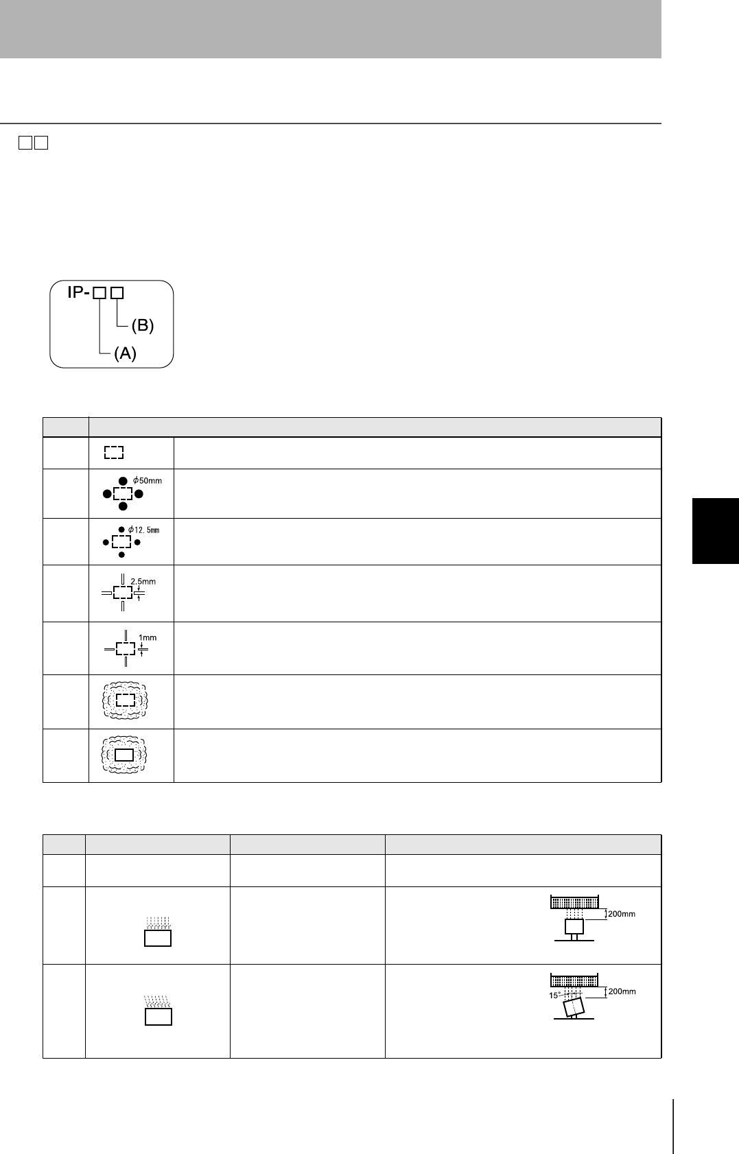
Protective Construction
IP- is governed by the test methods described below. Check in advance the seal characteristics under
the actual environment and conditions of use.
IP is the abbreviation of International Protection.
IEC (International Electrotechnical Commission)
Standard (IEC60529: 1989-11)
(A) First numeral in code: Class of protection against entry of solid foreign material
(B) Second numeral of code: Class of protection against the entry of water
Class Degree of protection
0 No protection
1 Protected against access by solid objects with a diameter of 50 mm or greater (e.g. human hands).
2 Protected against access by solid objects with a diameter of 125 mm or greater (e.g. fingers).
3 Protected against access by wires and solid bodies with a diameter of 25 mm or greater.
4 Protected against access by wires and solid bodies with a diameter of 1 mm or greater.
5 Entry of volumes of dust that would cause difficulties in normal operation of devices or compromise
safety is prevented.
6 Entry of dust is prevented.
Class Degree of protection Outline of test methods (tests using water)
0 No special protection No protection against the
entry of water. No test
1 Protection against droplets
of water The product suffers no ill
effects from droplets of water
falling vertically onto it.
Water droplets are
sprayed onto the product
from directly above for 10
minutes by water droplet
exposure test apparatus.
2 Protection against droplets
of water The product suffers no ill
effects from droplets of water
directed at it at an angle of up
to 15° to vertical.
The water droplet expo-
sure test apparatus is set
to 15° from vertical and
water droplets sprayed
onto the product for 10
minutes (total of 2.5 min-
utes in each direction).
120
SECTION 6
Protective Construction
CIDRW System
User’s Manual
SECTION 6
Appendix
3 Protection against spraying
water The product suffers no ill
effects from a water spray
directed at it at up to 60° from
vertical.
Using the test apparatus
shown in the figure to the
right, water is sprayed
from both directions, onto
both sides of the product,
at angles up to 60° from
vertical for 10 minutes.
4 Protection against splashing
water The product suffers no ill
effects from water splashed
on it from all directions.
Using the test apparatus
shown in the figure to the
right, water is splashed
onto the product from all
directions for 10 minutes.
5 Protection against water
jets The product suffers no ill
effects from a water jet aimed
directly at it from all directions.
Using the test apparatus
shown in the figure to the
right, a water jet is directed
at the product from all
directions for 1 minute per
square meter of outer cas-
ing, with a minimum total
exposure of 3 minutes.
6 Protection against powerful
jets of water Water does not enter the
product when a powerful jet of
water is directed at it from all
directions.
Using the test apparatus
shown in the figure to the
right, a water jet is directed
at the product from all
directions for 1 minute per
square meter of outer cas-
ing, with a minimum total
exposure of 3 minutes.
7 Protection against immer-
sion in water No entry of water on
immersion in water at the
stipulated pressure for the
stipulated time.
Immerse in water for 30
minutes at a depth of 1
meter (when the height of
the apparatus is less than
850 mm).
8 Protection against
immersion in water The product can be used
while continually immersed in
water.
Depends on arrange-
ments made between the
manufacturer and the user
of the product.
Class Degree of protection Outline of test methods (tests using water)
0.07 L/min.
per hole in the
spray nozzle
0.07 L/min.
per hole in the
spray nozzle
Diameter of spray
nozzle head: φ6.3
Diameter of spray
nozzle head: φ12.5
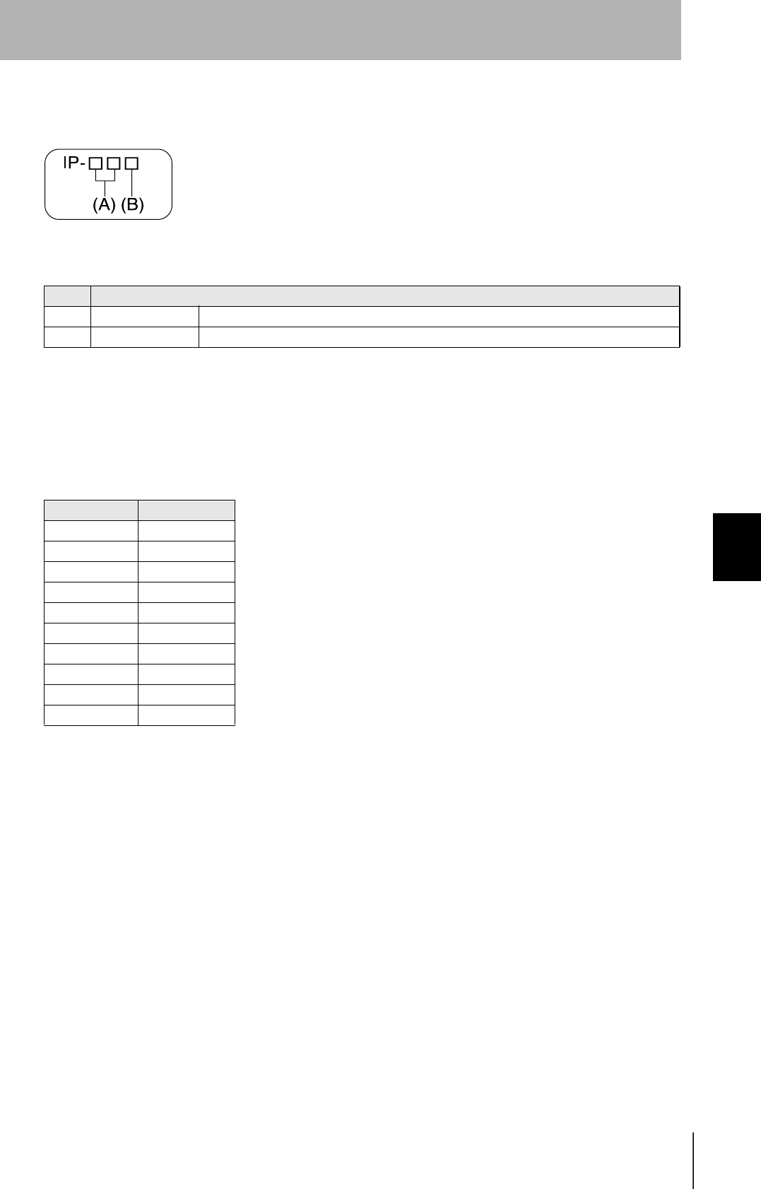
CIDRW System
User’s Manual
SECTION 6
Protective Construction
SECTION 6
Appendix
121
JEM (Japan Electrical Manufacturers’s association)
Standard (JEM1030 : 1991)
(A) is consistent with IEC60529 code numbers 1 and 2.
(B) class offering protection against entry of oil
Note: There are also classes c, d, and e.
NEMA (National Electrical Manufacturers' Association)
Table for conversions between NEMA enclosure ratings and IEC60529 (conversion the other way is
not possible)
Class Degree of protection
f Oil-proof model The product is not harmed by oil droplets and oil jets from all directions.
g Oil-resistant model Oil does not enter the product when oil droplets and oil jets are directed at it from all directions.
NEMA250 IEC60529
1IP10
2IP11
3IP54
3R IP14
3S IP54
4,4X IP56
5IP52
6,6P IP67
12,12K IP52
13 IP54
Note: From Annex A of the NEMA 250 standard. The differ-
ences between the NEMA enclosure ratings and
IEC60529 include points such as corrosion, rust resis-
tance, and wettability.

122
SECTION 6
Index
CIDRW System
User’s Manual
SECTION 6
Appendix
Index
A
Amplifier Unit 23, 30
Amplifier Unit Indicators 90
Amplifier Unit V640-HAM11 16
ASCII Code Table 118
B
Byte Write 80
C
Change the data segment area 48
Change the response time-out time 51
Changing the Position of the Mode
Switch on the Bottom of the Unit 44
Characteristic Data depending on
Conditions of Use 101
CIDRW Controller 22, 27
CIDRW Controller V700-L21 15
CIDRW Head 24
CIDRW Head V640-HS61 17
CIDRW Systems that Conform to
SEMI Standards (SEMI E99, E5, E4) 13
Coaxial Mounting 102
Command 75
Command/Response Format 74
Characteristics vs. Ambient Noise 110
Communications Test 59
Communications Time 107
Component Names and Functions 15
Connections and Wiring 27
Connector for connecting a CIDRW Head 30
Controller Indicators 84
D
Data Reading and Writing 24
Data Segment Area 111
F
Features 13
Flowchart for Getting Started 19
For Coaxial Installation 105
For Face-to-Face Installation 105
For Parallel Installation 105
From Installation to Trial Operation 91
From Trial Operation to Communications 93
H
Host Connection Port 38
I
ID Tag ↔ CIDRW System
Communications Test 60
IEC (International Electrotechnical
Commission) Standard (IEC605291989-11) 119
Influence of Background Metal on ID Tag 25
Influence of Background Metals
(Reference Only) 106
Influence of Noise 25
Installation 22
J
JEM (Japan Electrical Manufacturers’s
association) Standard (JEM10301991) 121
L
Link Unit 26, 37
Link unit V700-L11 18
List of Error Messages 84, 90
M
Maps of Communications Areas
(Reference Only) 102
Message Specifications 64
Mounting 25
Multi-connection port 41
Mutual Interference Distances
(Reference Only) 105
N
NAK 82
NEMA (National Electrical Manufacturers'
Association) 121
Noise measurement 82
Normal Operation Mode 85
O
Operation Check Flowchart 85, 91
Operation Model 113

CIDRW System
User’s Manual
SECTION 6
Index
SECTION 6
Appendix
123
Index
P
Parallel Mounting 103
Positional Relationship between
the CIDRW Head and the ID Tag 24
Power Supply 37
Power Supply and Grounding Wires 27, 30
Protective Construction 119
Protocol Specifications 114
R
READ 76
Regular Inspection 112
RESET 82
Return to the Normal Operation mode 53
RS-232C Port 32
RS-485 Port 35
S
Same Write 79
SECS port 28
SECS Protocol Specifications 113
Sending a Switching Command from
the Host Device 45
Set the Communications Conditions for
Amplifier Units 55
Set the Communications Conditions for
Link Units 57
Set the Communications Conditions for
the CIDRW Controller 44
Set the parameters for
the communications conditions 46
Setting Mode 88
Specifications and Dimensions 96
Specifications for Each Stream/Function 66
Start the terminal software 45
Support Attributes 116
Switch to the Setting mode 44
System Configuration 14
T
TEST 81
Test for Communications with the Host Device 59
V
Vertical Mounting 104
W
What is a CIDRW System? 12
When SECS is Not Used 59, 62, 74, 90
When SECS is Used 14, 59, 60, 64, 84
When the Mode is Selected
by a Command Sent from the Host Device 53
When the Mode is Selected with
the Mode Switch on the Bottom of the Unit 53
WRITE 77

CIDRW System
User’s Manual
ëÊ 6 èÕ
124
Revision History
A manual revision code appears as a suffix to the catalog number on the front cover of the manual.
The following table outlines the changes made to the manual during each revision. Page numbers refer to the previous
version.
Revision code Date Revised content
1 January 2003 Original production
Cat. No. Z167-E1-1
Revision code
OM
R
ON
C
orporation
Industrial Automation Company
Sensing Devices and Components Division H.Q.
FA Auto-identification Components Department
Shiokoji Horikawa, Shimogyo-ku, Kyoto, 600-8530 Japan
Tel : (81)75-344-7069 / Fax : (81)75-344-7107
Regional Headquarters
____________________
OMRON EUROPE B.V.
Sensor Business Unit
Carl-Benz-Str. 4, D-71154 Nufringen,
Germany
Tel : (49)7032-811-0 / Fax : (49)7032-811-199
OMRON ELECTRONICS LLC
1 East Commerce Drive, Schaumburg, IL 60173
U.S.A.
Tel : (1)847-843-7900 / Fax : (1)847-843-8568
OMRON ASIA PACIFIC PTE. LTD.
83 Clemenceau Avenue, #11-01, UE Square,
239920 Singapore
Tel : (65)835-3011 / Fax : (65)835-2711
OMRON CHINA CO., LTD.
BEIJING OFFICE
Room 1028, Office Building,
Beijing Capital Times Square,
No.88 West Chang'an Road,
Beijing, 100031 China
Tel : (86)10-8391-3005 / Fax : (86)10-8391-3688

Cat. No. Z167-E1-01 Note: Specifications subject to change without notice.
Authorized Distributor: