Omron 6CYCIDV6400202 Carrier ID Reader/Writer User Manual Manual Part One
Omron Corporation Carrier ID Reader/Writer Manual Part One
Omron >
Contents
Manual Part One

Cat. No. Z167-E1-01
USER'S MANUAL
CIDRW SYSTEM
V640 SERIES
CIDRW CONTROLLER
V700-L21
AMPLIFIER UNIT
V640-HAM11
CIDRW HEAD
V640-HS61
LINK UNIT
V700-L11

Special or Critical Applications
When the CIDRW System will be used in one of the conditions or applications listed below, allow extra safety margins in
ratings and functions, add extra safety feature such as fail-safe systems, and consult your OMRON representative.
• Operating conditions or environments which are not described in the manual.
• Nuclear power control systems, railroad systems, aviation systems, vehicles, combustion systems, medical equipment,
amusement equipment, or safety equipment.
• Other systems, machines, and equipment that may have a serious influence on lives and property and require extra
safety features.
Product Availability
Some of the products listed may not be available in some countries. Please contact your nearest OMRON sales
office by referring to the addresses provided at the back of this manual.
OMRON, 2003
All rights reserved. No part of this publication may be reproduced, stored in a retrieval system, or transmitted, in
any form, or by any means, mechanical, electronic, photocopying, recording, or otherwise, without the prior written
permission of OMRON.
No patent liability is assumed with respect to the use of the information contained herein. Moreover, because
OMRON is constantly striving to improve its high-quality products, the information contained in this manual is sub-
ject to change without notice. Every precaution has been taken in the preparation of this manual. Nevertheless,
OMRON assumes no responsibility for errors or omissions. Neither is any liability assumed for damages resulting
from the use of the information contained in this publication.

ÇÕǹÇ?Ç ëÊ 1 èÕ ëÊ 2 èÕ ëÊ 3 èÕ ëÊ 4 èÕ
INTRODUCTION
SECTION 1 SECTION 2 SECTION 3 SECTION 4 SECTION 5 SECTION 6
Introduction
SECTION 1
SECTION 2
SECTION 3
SECTION 4
SECTION 5
SECTION 6
Table of Contents/Precautions on Safety
Product Outline
Installation and Connections/Wiring
Preparing for Communications
Reading from/Writing to ID Tags
Troubleshooting
Appendix
CIDRW System
V640-HAM11 Amplifire Unit
V640-HS61 CIDRW Head
V700-L21 CIDRW Controller
V700-L11 Link Unit
User's Manual

2
INTRODUCTION
Table of Contens
CIDRW System
User’s Manual
INTRODUCTION
Table of Contents
Table of Contents
Introduction 1
Table of Contents 2
General Safety Precautions 4
General Safety Precautions 4
Warning 4
Caution 4
Notice 5
Applicable SEMI Standards 7
Applicable Standards 8
Editor’s Note 10
SECTION 1 Product Outline 11
What is a CIDRW System? 12
Features 13
System Configuration 14
Component Names and Functions 15
Flowchart for Getting Started 19
SECTION 2 Installation and Connections/Wiring 21
Installation 22
Connections and Wiring 27
SECTION 3 Preparing for Communications 43
Set the Communications Conditions for the CIDRW Controller 44
Set the Communications Conditions for Amplifier Units 55
Set the Communications Conditions for Link Units 57
Communications Test 59
SECTION 4 Reading from/Writing to ID Tags 63
When SECS is Used 64
When SECS is Not Used 74

3
CIDRW System
User’s Maual
INTRODUCTION
Table of Contents
INTRODUCTION
Table of Contents
SECTION 5 Troubleshooting 83
When SECS is Used 84
When SECS is Not Used 90
SECTION 6 Appendix 95
Specifications and Dimensions 96
System Configuration Examples 100
Characteristic Data depending on Conditions of Use 102
Data Segment Area 111
Regular Inspection 112
SECS Protocol Specifications 113
ASCII Code Table 118
Protective Construction 119
Revision History 124

4
INTRODUCTION
General Safety Precautions
CIDRW System
User’s Manual
INTRODUCTION
General Safety Precautions
OMRON products are manufactured for use according to proper procedures by a qualified operator and only for the
purposes described in this manual.
The following conventions are used to indicate and classify precautions in this manual. Always heed the information
provided with them. Failure to heed precautions can result in injury to people or damage to property.
DANGER
Indicates an imminently hazardous situation which, if not avoided, will result in death or serious injury.
WARNING
Indicates a potentially hazardous situation which, if not avoided, could result in death or serious injury.
Caution
Indicates a potentially hazardous situation which, if not avoided, could result in minor or moderate injury, or property
damage.
WARNING
Failure to read and understand the information provided in this manual may result in personal injury or death, damage to
the product, or product failure. Please read each section in its entirety and be sure you understand the information
provided in the section and related sections before attempting any of the procedures or operations given.
Caution
General Safety Precautions
To ensure safety, observe the following points.
Caution • Do not insert water or wires through gaps in the case. This could cause fire or electric shock.
Caution • In the event of a malfunction, stop using the product immediately, turn off the power, and
consult your OMRON dealer.
Caution • Dispose of this product as industrial waste.
Caution

5
CIDRW System
User’s Manual
INTRODUCTION
Notice
INTRODUCTION
Notice
The CIDRW System is highly reliable and resistant to most environmental factors. The following guidelines, however, must
be followed to ensure reliability and optimum use of the CIDRW System.
Installation Site
Install the product at a location where:
• It is not exposed to direct sunlight.
• It is not exposed to corrosive gases, dust, metal chips, or salt.
• The working temperature is within the range stipulated in the specifications.
• There are no sudden variations in temperature (no condensation).
• The relative humidity is within the range stipulated in the specifications.
• No vibration or shock exceeding the values stipulated in the specifications is transmitted directly to
the body of the product.
• It is not subject to splashing water, oil, or chemical substances.
Mounting
• This product communicates with ID Tags using the 134 kHz frequency band. Note that some trans-
ceivers, motors, monitoring equipment, and power supplies (power supply ICs) generate electrical
waves (noise) that interfere with communications with ID Tags. If you are using the product in the
vicinity of any of these devices, check the effect on communications in advance.
• In order to minimize the effects of noise, ground nearby metal bodies with a grounding resistance not
exceeding 100 ohms.
• When mounting Amplifier Units, tighten the screws with a torque no greater than 1.2 N·m.
• When mounting CIDRW Heads, tighten the screws with a torque no greater than 0.6 N·m.
• When multiple CIDRW Heads are mounted next to each other, communications performance could
be impaired by mutual interference. Note the information in this manual on mutual interference when
installing multiple heads.
Refer to page 105.

6
INTRODUCTION
Notice
CIDRW System
User’s Manual
INTRODUCTION
Power and Ground Cables
• Use the power supply voltage specified in this manual.
• Ensure correct polarity when connecting to the +/- power supply terminals.
• The ground terminals must be connected to a ground with a grounding resistance not exceeding 100
ohms.
Wiring Work
• Always turn the power off before starting wiring work or connecting/disconnecting cables.
• Do not run high-voltage lines and power lines though the same conduit.
• To prevent damage by static electricity, wear a wrist strap or equivalent, and take measures to pre-
vent charging, before touching terminal components or parts inside connectors.
Screw Locking Adhesive
• Screw locking adhesive (screw lock) may cause deterioration and cracking of resin parts: do not use
it for screws in resin parts or anywhere where resin washers are used.
Cleaning
• Do not use organic solvents such as thinner or benzene.

7
CIDRW System
User’s Manual
INTRODUCTION
Applicable SEMI Standards
INTRODUCTION
Applicable SEMI Standards
This CIDRW system complies with the following standards.
• SEMI E99 THE CARRIER ID READER/WRITER FUNCTIONAL STANDARD
• SEMI E5 EQUIPMENT COMMUNICATION STANDARD 2 MESSAGE CONTENT (SECS II)
• SEMI E4 EQUIPMENT COMMUNICATION STANDARD 1 MESSAGE TRANSFER (SECS I)
SEMI is the acronym for Semiconductor Equipment and Materials International.
SECS is the acronym for SEMI Equipment Communications Standard.

8
INTRODUCTION
Applicable Standards
CIDRW System
User’s Manual
INTRODUCTION
Applicable Standards
1. FCC Rules (Federal Communications Commission)
This device complies with Part 15 Subpart C of the FCC Rules.
FCC ID: E4E6CYCID6400202
Operation is subject to the following two conditions:
(1) this device may not cause harmful interference, and
(2) this device must accept any interference received, including interference that may cause undesired oper-
ation.
FCC NOTICE
This equipment has been tested and found to comply with the limits for a Class B digital device, pursu-
ant to part 15 of the FCC Rules. These limits are designed to provide reasonable protection against
harmful interference in a residential installation.
This equipment generates, uses and can radiate radio frequency energy and, if not installed and used
in accordance with the instructions, may cause harmful interference to radio communications. How-
ever, there is no guarantee that interference will not occur in a particular installation. If this equipment
does cause harmful interference to radio or television reception, which can be determined by turning
the equipment off and on, the user is encouraged to try to correct the interference by one or more of
the following measures:
• Reorient or relocate the receiving antenna
• Increase the separation between the equipment and receiver.
• Connect the equipment into an outlet on a circuit different from that to which the receiver is
connected.
• Consult the dealer or an experienced radio/TV technician for help.
FCC WARNING
Changes or modifications not expressly approved by the party responsible for compliance could void
the user's authority to operate the equipment.
Properly shielded and grounded cables and connectors must be used for connection to host
computer and/or peripherals in order to meet FCC emission limits.
CAUTION
This device must be professionally installed.
This CIDRW Head [Model: V640-HS61 (-X)] is dedicated to Amplifier Unit [Model: V640-HAM11 (-X)].

9
CIDRW System
User’s Manual
INTRODUCTION
Applicable Standards
INTRODUCTION
2. EC Declaration of Conformity
Hereby, Omron, declares that this V640(-X) is in compliance with the essential requirements and other
relevant provisions of Directive 1999/5/EC, and satisfy tests for the appropriate requirements of the following
relevant standards.
Radio: EN300 330 V1.2.1 (May 1999)
EMC: EN301 489-3 (EN301 489-1)
Safety: EN61010-1: 1993+A2
Countries of intended use:
Austria, Belgium, Denmark, Finland, France, Germany, Iceland, Ireland, Italy, Liechtenstein, Luxem-
bourg, Netherlands, Norway, Portugal, Spain, Sweden, Switzerland, United Kingdom
English Hereby, Omron, declares that this V640(-X) is in compliance with the essential
requirements and other relevant provisions of Directive 1999/5/EC.
Finnish Omron vakuuttaa täten että V640(-X) tyyppinen laite on direktiivin 1999/5/EY oleellis-
ten vaatimusten ja sitä koskevien direktiivin muiden ehtojen mukainen.
Dutch Hierbij verklaart Omron dat het toestel V640(-X) in overeenstemming is met de
essentiële eisen en de andere relevante bepalingen van richtlijn 1999/5/EG
French Par la présente Omron déclare que l'appareil V640(-X) est conforme aux exigences
essentielles et aux autres dispositions pertinentes de la directive 1999/5/CE
Swedish Härmed intygar Omron att denna V640(-X) står I överensstämmelse med de
väsentliga egenskapskrav och övriga relevanta bestämmelser som framgår av direk-
tiv 1999/5/EG.
Danish Undertegnede Omron erklærer herved, at følgende udstyr V640(-X) overholder de
væsentlige krav og øvrige relevante krav i direktiv 1999/5/EF
German Hiermit erklärt Omron, dass sich dieser/diese/dieses V640(-X) in Übereinstimmung
mit den grundlegenden Anforderungen und den anderen relevanten Vorschriften der
Richtlinie 1999/5/EG befindet". (BMWi)
Italian Con la presente Omron dichiara che questo V640(-X) è conforme ai requisiti essen-
ziali ed alle altre disposizioni pertinenti stabilite dalla direttiva 1999/5/CE.
Spanish Por medio de la presente Omron declara que el V640(-X) cumple con los requisitos
esenciales y cualesquiera otras disposiciones aplicables o exigibles de la Directiva
1999/5/CE
Portuguese Omron declara que este V640(-X) está conforme com os requisitos essenciais e out-
ras disposições da Directiva 1999/5/CE.

10
INTRODUCTION
Editor’s Note
CIDRW System
User’s Manual
INTRODUCTION
Editor’s Note
Visual Aids
Indicates an explanation of a point that must be observed to ensure that the product is capable of its proper functions and perfor-
mance. Read this information carefully and follow the cautions: if the product is used incorrectly, data or the equipment itself
could be destroyed.
Indicates summaries of points of particular importance relating to product performance, e.g. points to note during operation and
advice on how to use the product.
Indicates the number of a page where related information can be found.
Indicates information for reference when you encounter a problem.
Indicator Statuses
The following symbols are used to show the status of the indicators on the CIDRW Controller and Amplifier
Units.
OFF
Flashing
ON

12
SECTION 1
What is a CIDRW System?
CIDRW System
User’s Manual
SECTION 1
Product Outline
What is a CIDRW System?
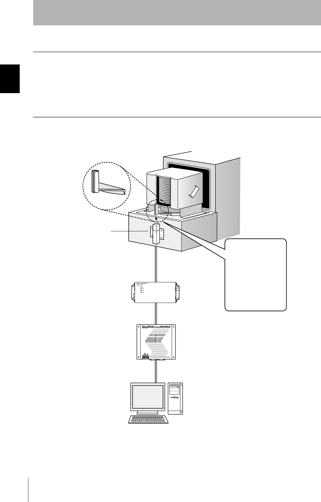
The CIDRW system writes data to, and reads data from, the carrier IDs (ID Tags) mounted on the carriers
(FOUP) in semiconductor manufacturing processes without contacting these ID Tags. CIDRW is the
abbreviation of "Carrier ID Reader/Writer" and this abbreviation is used throughout this manual.
Reading and writing information such as models, process instructions, lots, and inspection results to and from
ID Tags makes it possible to manage work instruction information from a host device.
Example: Management of information in semiconductor and wafer manufacturing processes
ID Tag
(holder is separate)
CIDRW Head
Reading and writing
information
• Model information
• Process instruction
information
• Completion
information
• Lot information
• Inspection results
Etc.
Host
Amplifier Unit
CIDRW Controller
13
CIDRW System
User’s Maual
SECTION 1
Features
SECTION 1
Product Outline
Features
CIDRW Systems that Conform to SEMI Standards (SEMI E99, E5, E4)
List of Applicable Standards
• SEMI E99 THE CARRIER ID READER/WRITER FUNCTIONAL STANDARD
• SEMI E5 EQUIPMENT COMMUNICATION STANDARD 2 MESSAGE CONTENT (SECS II)
• SEMI E4 EQUIPMENT COMMUNICATION STANDARD 1 MESSAGE TRANSFER (SECS I)
SEMI is the acronym for Semiconductor Equipment and Materials International.
SECS is the acronym for SEMI Equipment Communications Standard.
Host
SECS I/II
CIDRW Controller
V700-L21
Amplifier Unit
V640-HAM11
CIDRW Head
V640-HS61
ID Tag
RI-TRP-DR2B
(Made by Texas
Instruments)
CIDRW System Conforming to SEMI Standards
14
SECTION 1
System Configuration
CIDRW System
User’s Manual
SECTION 1
Product Outline
System Configuration
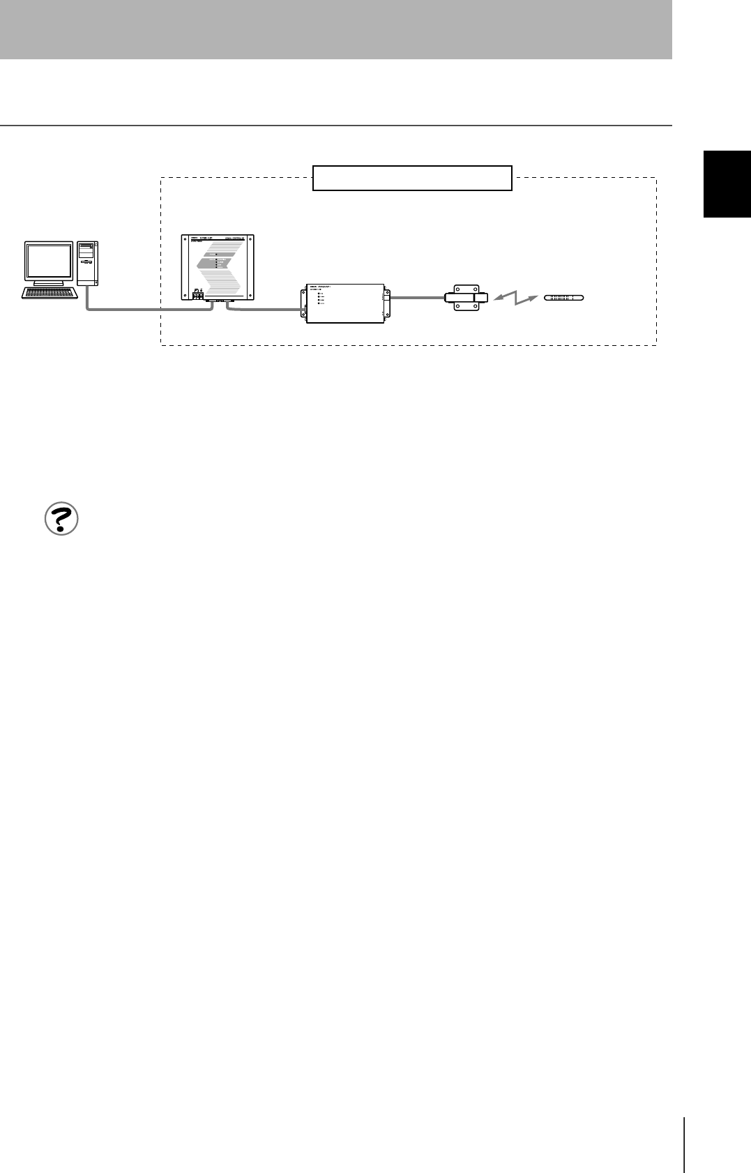
When SECS is Used
Communication with the host device is possible using the SECS protocol.
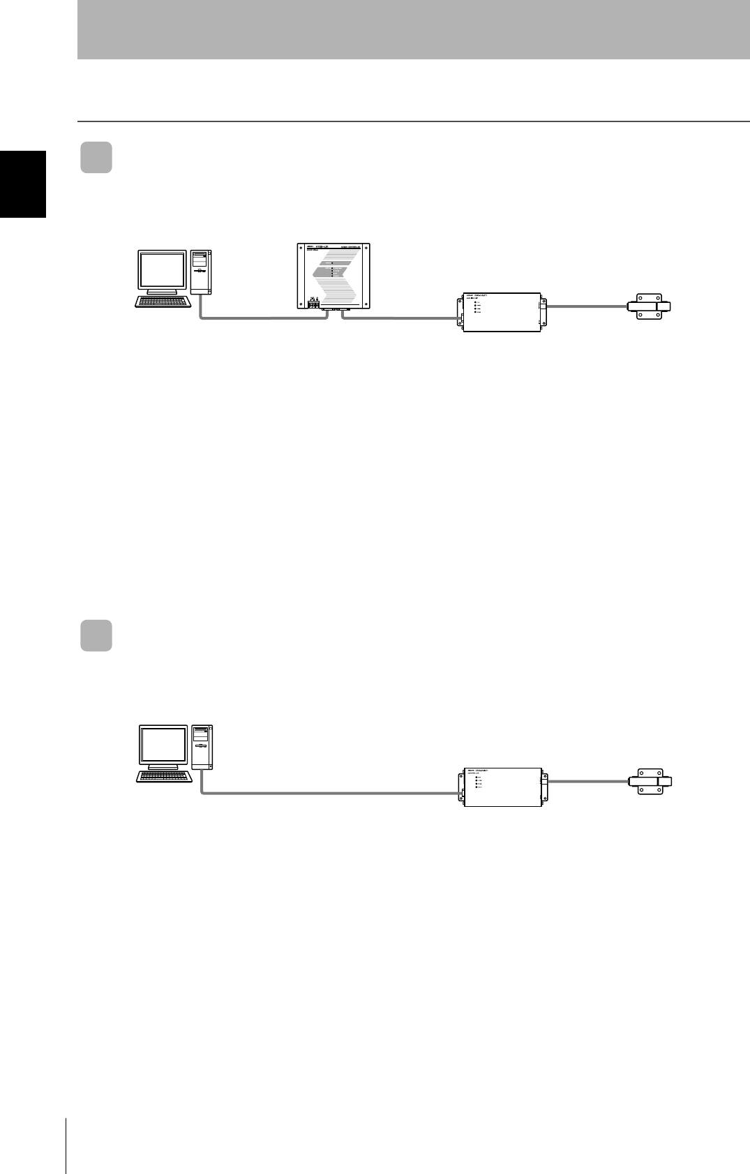
When SECS is Not Used
Communications with the host device follow the OMRON proprietary protocol.
The Amplifier Units are connected directly to the host device without using a CIDRW Controller.
These are antennae for
reading the carrier IDs
from the ID Tags and
writing the carrier IDs.
These are units that
control a CIDRW Head.
This is e.g. a host,
or equipment con-
troller.
CIDRW Head
V640-HS61
Amplifier Unit
V640-HAM11
CIDRW Controller
V700-L21
Host
Multiple Amplifier Units
are controlled in
response to commands
(SECS) from the host
device.
RS-232C
SECS I/II RS-232C
These are antennae for
reading the carrier IDs
from the ID Tags and
writing the carrier IDs.
These are units that
control a CIDRW Head.
This is e.g. a host,
or equipment con-
troller.
CIDRW Head
V640-HS61
Amplifier Unit
V640-HAM11
Host
RS-232C
OMRON proprietary protocol
15
CIDRW System
User’s Maual
SECTION 1
Component Names and Functions
SECTION 1
Product Outline
Component Names and Functions
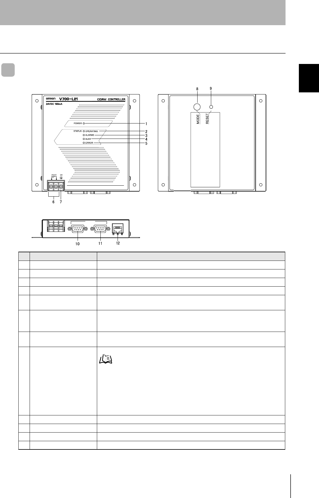
CIDRW Controller V700-L21
No. Name Function
1 Power indicator (green) An LED that indicates whether the power is ON or OFF. Lit while the power is ON.
2 OPERATING indicator (green) Lit while the CIDRW system status model is operating.
3 ALARMS indicator (green) Lit when the status of "AlamStatus" of the CIDRW system is "Alarm (1)."
4 BUSY indicator (green) Lit when the status of "OparationalStatus" of the CIDRW system is "BUSY."
5 ERROR indicator (red) When a processing error is detected (when SSACK is other than "NO"), this indicator is
lit for 50 ms.
6 24 VDC power supply termi-
nals
(with cover)
Connect to the 24 VDC power supply.
7 Frame ground terminal
(with cover)
The grounding wire is connected here. (Ground to 100 Ω or less)
8 MODE switch Used to select the mode of operation.
Refer to page 44.
0 : Normal Operation mode. When mounting the Controller, set the switch to this posi-
tion.
3 : Setting mode, selected to set information such as the communication conditions.
When the switch on the bottom face of the Controller cannot be accessed, the opera-
tion mode can be changed from the host device while the switch is left at the "0" set-
ting.
1 - 2, 4 - 7 : Setting prohibited
9 RESET switch Restarts the CIDRW Controller.
10 SECS port Port for connecting the host device. Conforms to SECS I/II.
11 ID port An Amplifier Unit or Link Unit is connected here.
12 Maintenance port (with cover) Not used. Do not remove the cover.
45%
5'%5 +& /#+06'0#00%'
16
SECTION 1
Component Names and Functions
CIDRW System
User’s Manual
SECTION 1
Product Outline
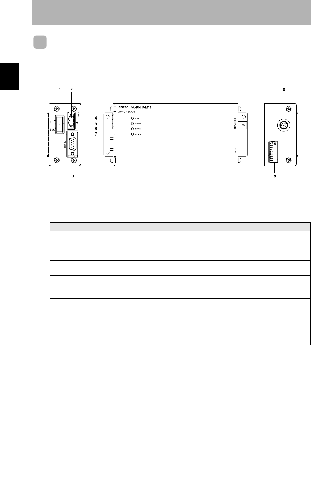
Amplifier Unit V640-HAM11
No. Name Function
1 Dedicated power supply con-
nector
Connect to the 24 VDC power supply.
2 RS-485 port When using multiple CIDRW Heads, connect this to the RS-485 port of another Amplifier
Unit or to the multi-connection port of a Link Unit.
3 RS-232C port Connected to a CIDRW Controller or a host device.
Uses the OMRON proprietary communications protocol.
4 RUN indicator (green) Turns ON when the Amplifier Unit is in normal operation.
5 COMM indicator (yellow) Turns ON during communications with the host device or during communications with an
ID Tag.
6 NORM indicator (green) Turns ON when the communications finish with no error.
7 ERROR indicator (red) Turns ON when an error occurs during communication with the host device, or during
communication with an ID Tag.
8 CIDRW Head connection port A CIDRW Head is connected here.
9 Setting DIP switches Used to set the node number, the communications conditions, and the RS-485 terminal
resistance.
17
CIDRW System
User’s Maual
SECTION 1
Component Names and Functions
SECTION 1
Product Outline
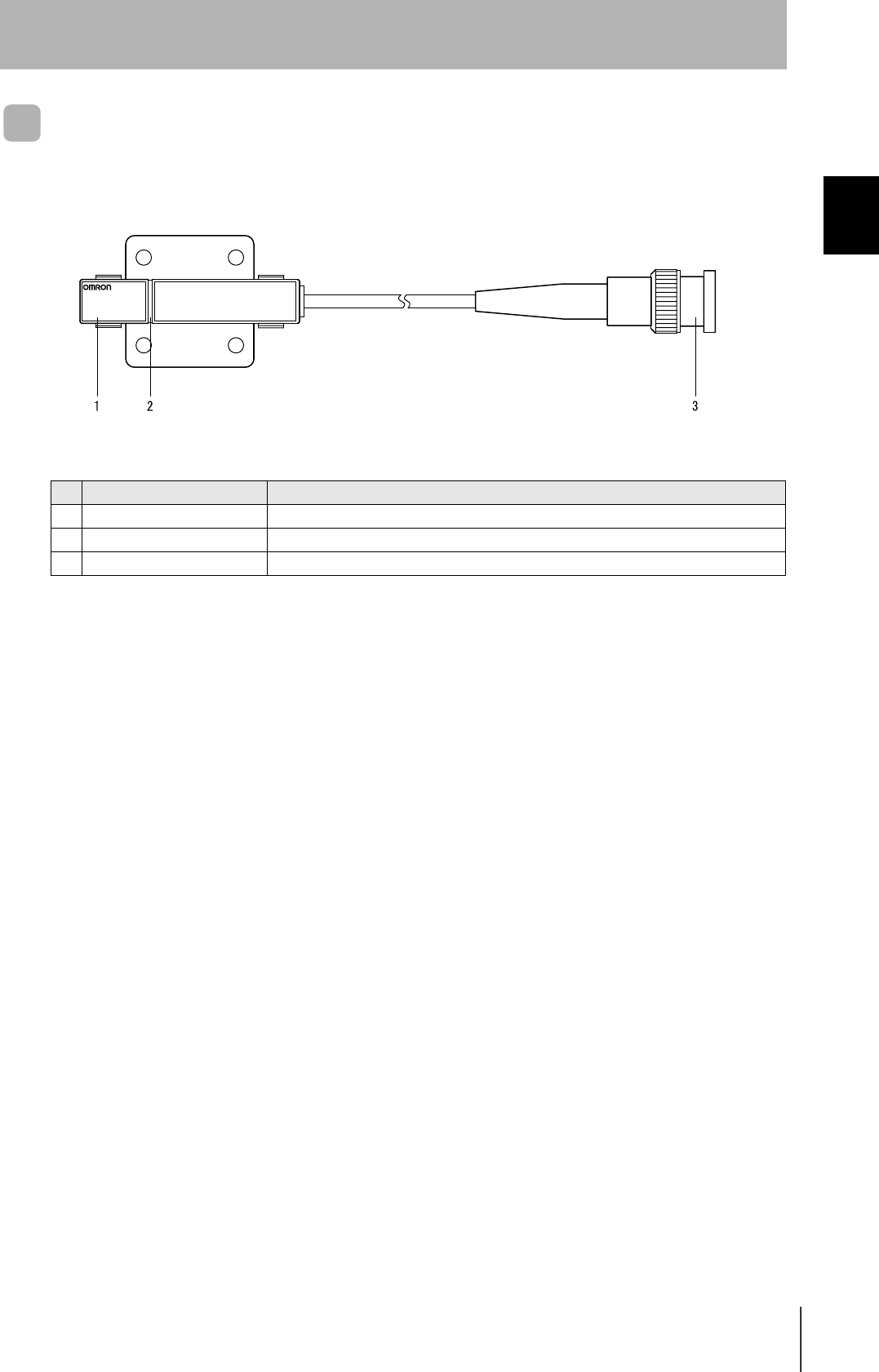
CIDRW Head V640-HS61
No. Name Function
1 Antenna Used to communicate with ID Tags.
2 Antenna center This is the center of the communications area.
3 Connector Connect to an Amplifier Unit.
V640-HS61
CIDRW HEAD
18
SECTION 1
Component Names and Functions
CIDRW System
User’s Manual
SECTION 1
Product Outline
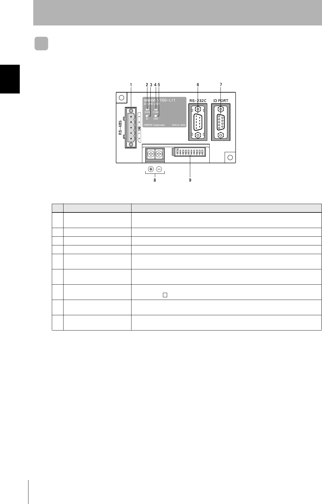
Link unit V700-L11
No. Name Function
1 Multi-connection port
(RS-485)
This is the port that connects to the Amplifier Units when multiple CIDRW Heads are
connected to a CIDRW Controller. The GR (frame ground) terminal is also at this port.
2 RUN indicator (green) Turns ON while the Link Unit is in normal operation.
3 ID indicator (green) Turns ON during data communications with a V700 series IDRW Head.
4 COMM indicator (green) Turns ON during data communications with the host device.
5 ERR indicator (red) Turns ON when an error occurs during data communications with the host device or
head.
6 Host device connection port
(RS-232C)
This is a port for connecting to the CIDRW Controller via an RS-232C interface. A dust
cover is fitted on shipment from the factory. Remove this cover before using the port.
7 ID connection port This is a dedicated port for connecting a V700 series IDRW Head. Connect either a
V700-HMD13 or V700-HMD11-1 IDRW Head.
8 24 V power supply terminals
(inside the cover)
Connect to the 24 VDC power supply.
9 Setting DIP switches
(inside the cover)
Used to set the equipment number, the communications conditions, and the RS-485 ter-
minal resistance.
19
CIDRW System
User’s Maual
SECTION 1
Flowchart for Getting Started
SECTION 1
Product Outline
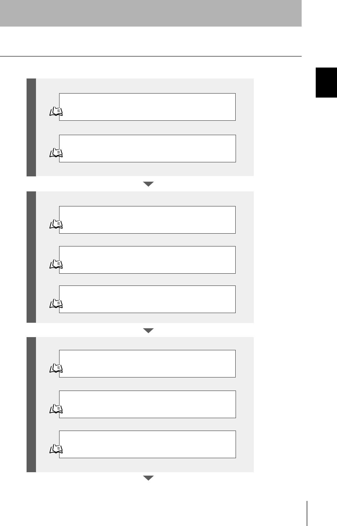
Flowchart for Getting Started
Refer to page 22.
Refer to page 27.
Refer to page 44.
Refer to page 55.
Refer to page 59.
Refer to page 60.
Installation
Connection and Wiring
Set the Communications Conditions for the CIDRW Controller
Set the Communications Conditions for Amplifier Units
Refer to page 57.
Set the Communications Conditions for Link Units
Test for Communications with the Host Device
ID Tag <-> CIDRW System Communications Test
Check the Surrounding Environment
Refer to page 24.
Preparation for CommunicationsTrial Operation Installation and Connections
20
SECTION 1
Flowchart for Getting Started
CIDRW System
User’s Manual
SECTION 1
Product Outline
Refer to page 64.
Refer to page 74.
Refer to page 84. List of Error Messages
Refer to page 84. Controller Indicators
Refer to page 85. Operation Check Flowchart
Refer to page 90. List of Error Messages
Refer to page 90. Amplifier Unit Indicators
Refer to page 91. Operation Check Flowchart
When SECS is Used
When SECS is Not Used
When SECS is Not Used
When SECS is Used
When you Encounter a Problem...
Communications

22
SECTION 2
Installation
CIDRW System
User’s Manual
SECTION 2
Installation and Connections/Wiring
Installation
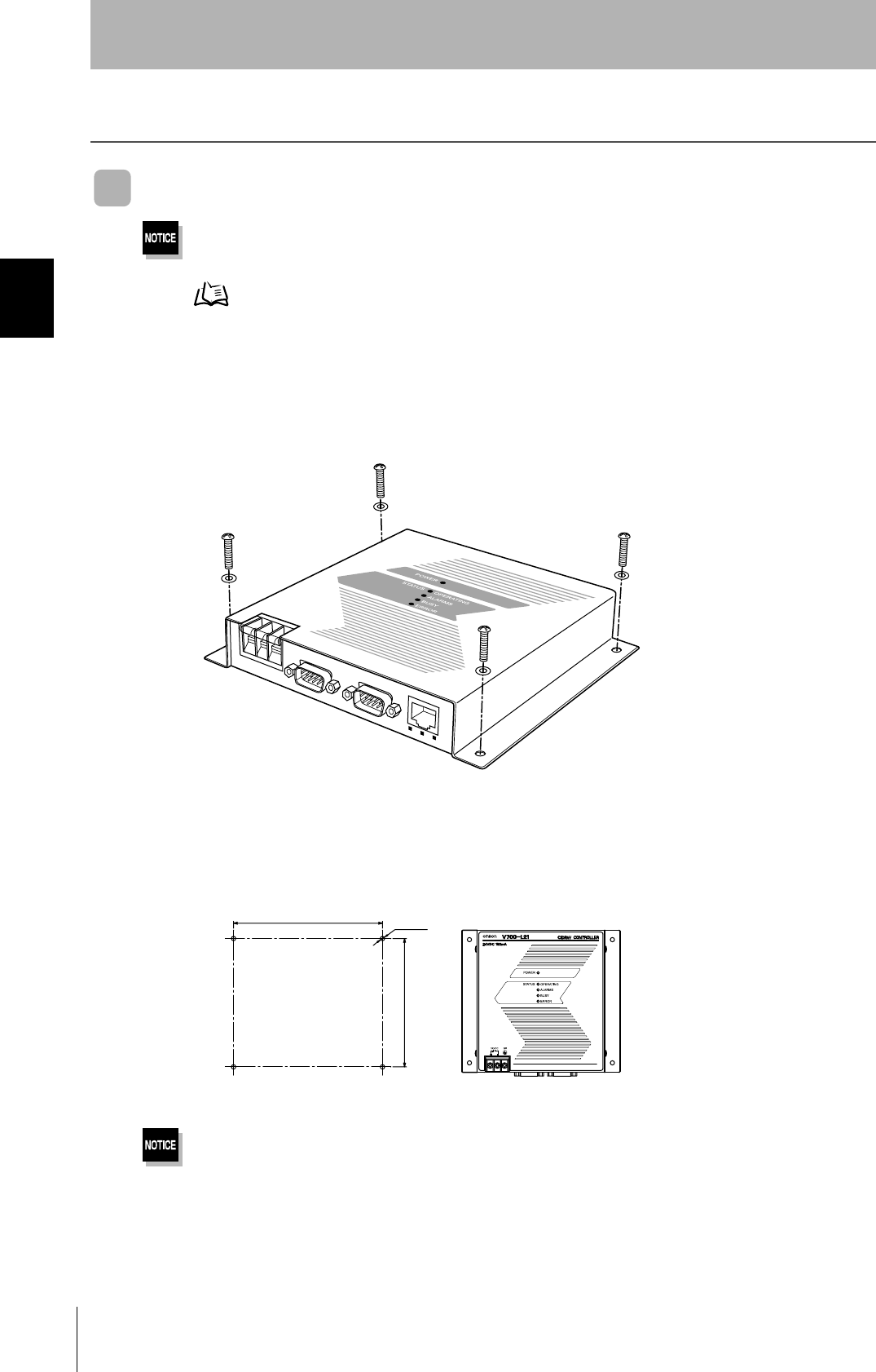
CIDRW Controller
There is a switch for selecting the operation mode (Normal Operation mode <-> Setting mode) on the bottom face of the
CIDRW Controller. Set the communications conditions in the Setting mode (switch position 3) before mounting the
CIDRW Controller.
Refer to page 44.
Set the Controller to the Normal Operation mode (switch position 0) when mounting it.
Mount the CIDRW Controller with the resin washers and four M4 screws provided as accessories.
•Tighten the M4 screws with a torque not exceeding 1.2 N·m.
• Do not apply organic solvents used with screw locking agents at the locations where the screws are inserted.
r
r /
Mounting dimensions
(Unit: mm)
23
CIDRW System
User’s Manual
SECTION 2
Installation
SECTION 2
Installation and Connections/Wiring
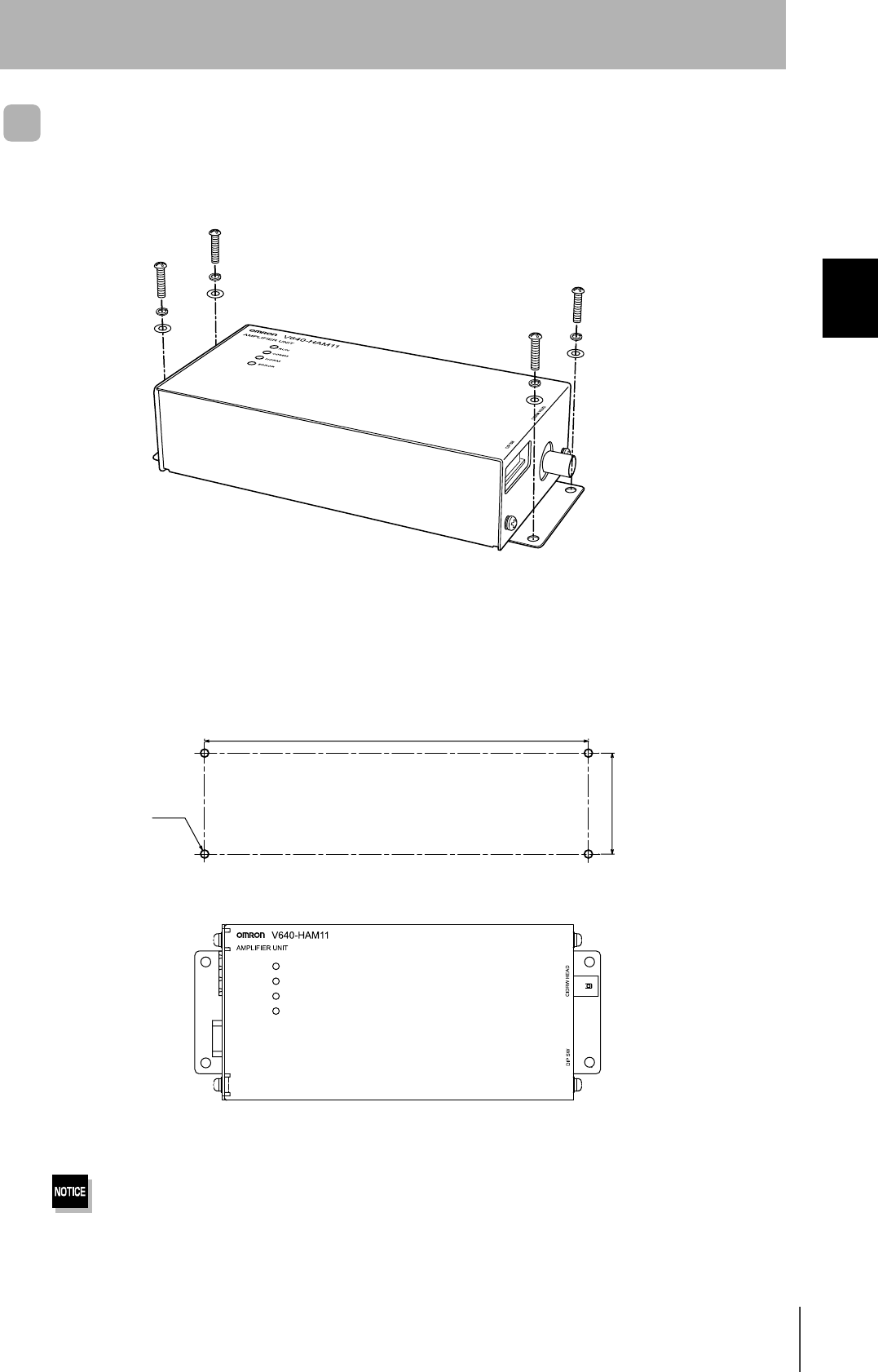
Amplifier Unit
Use spring washers and flat washers with the four M4 screws when mounting the Amplifier Unit.
Tighten the M4 screws with a torque not exceeding 1.2 N·m.
r
r
/
RUN
COMM
NORM
ERROR
Mounting dimensions
(Unit: mm)
24
SECTION 2
Installation
CIDRW System
User’s Manual
SECTION 2
Installation and Connections/Wiring
CIDRW Head
The area for communications with ID Tags varies substantially according to the installation orientations
and the background conditions (metals, noise, etc.). Check the communications area before deciding
the installation position.
For details on actual communications distances, see Characteristic Data depending on Conditions of
Use in Appendix.
Refer to page 101.
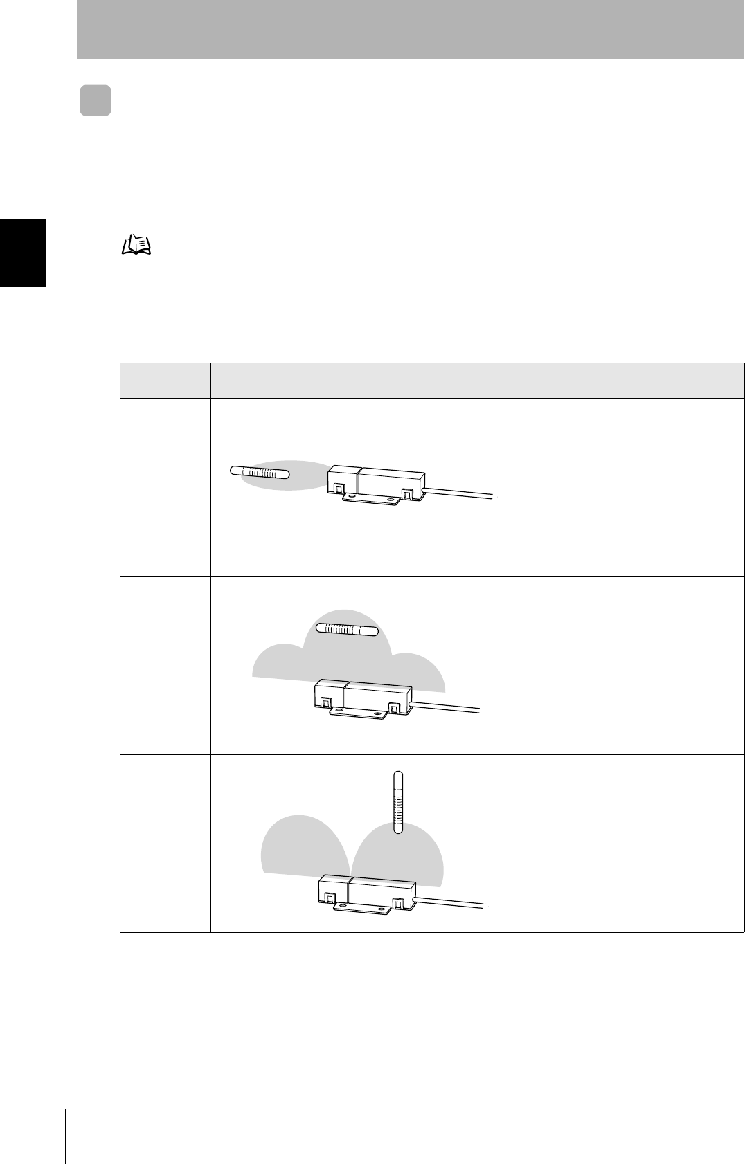
Positional Relationship between the CIDRW Head and the ID Tag
The communications area differs according to the positional relationship during communications.
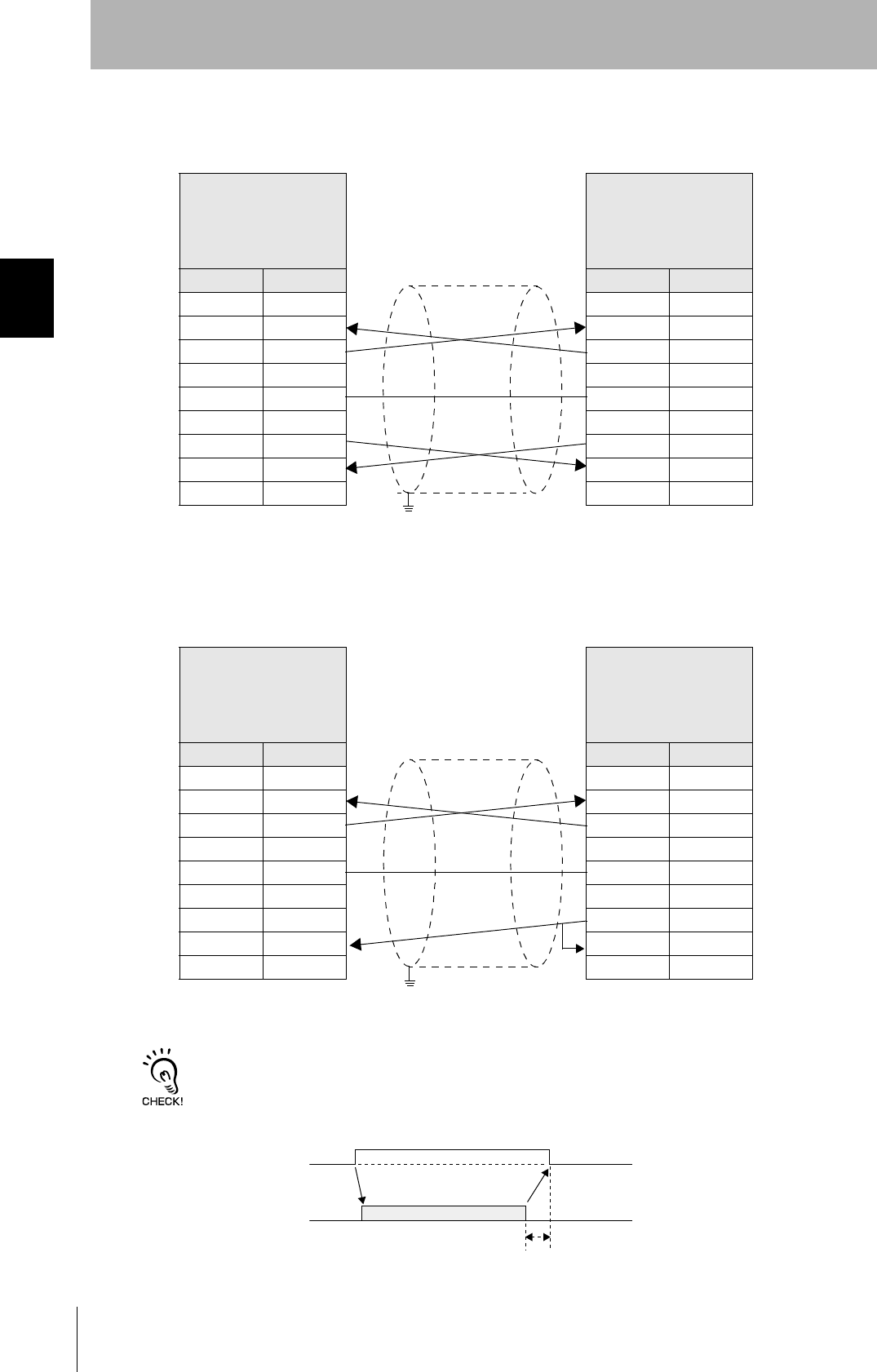
Data Reading and Writing
The communications distances for reading and writing are not the same; the distance is shorter for
writing. Therefore, when data is to be both read and written, take the distance for writing as the refer-
ence distance when installing the CIDRW Head and the ID Tag.
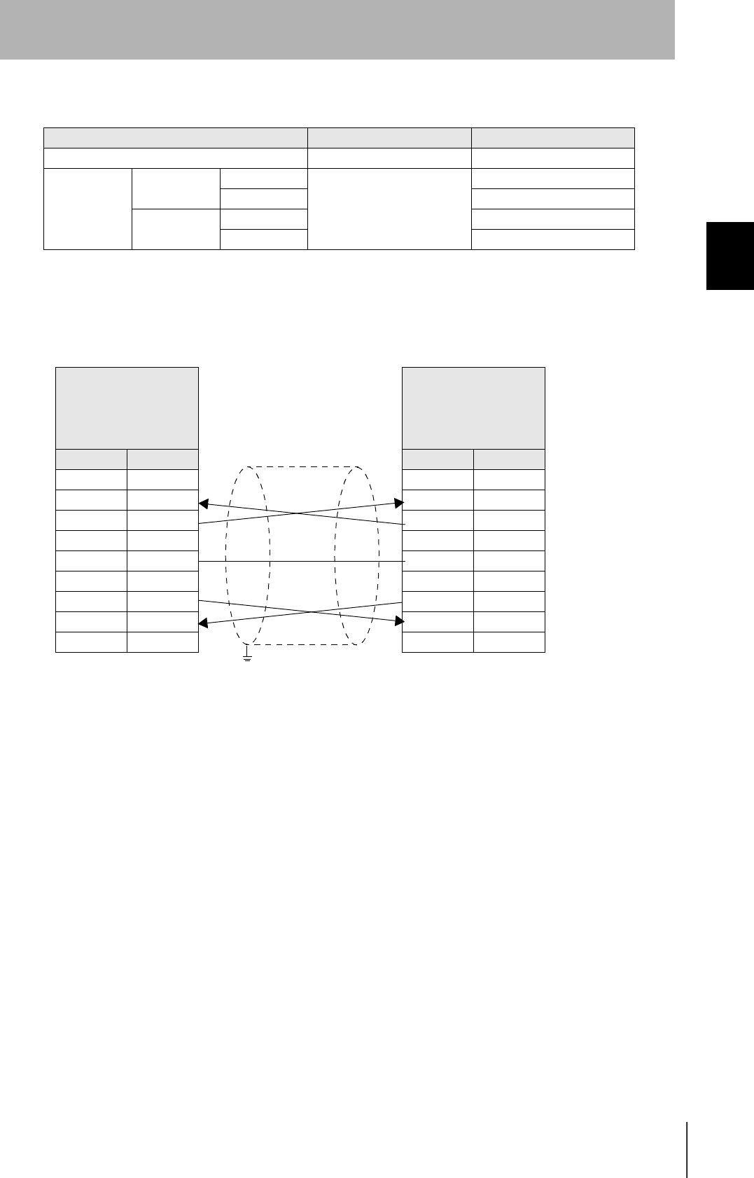
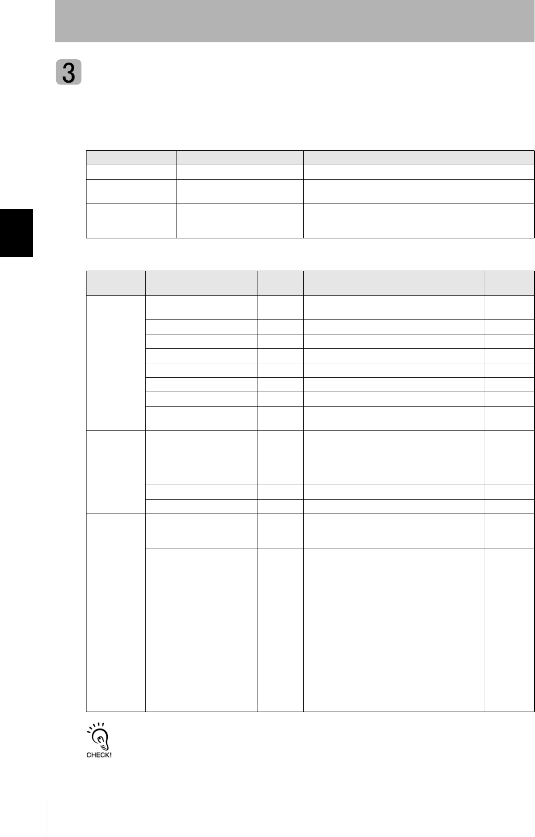
Mounting
orientation Communications area (purely illustrative) Explanation
Coaxial The maximum communications area is
obtained when the centerlines of the CIDRW
Head and the ID Tag coincide.
Parallel The maximum communications area is
obtained when the center point of the
antenna on the CIDRW Controller is aligned
with the centerline of the ID Tag.
Vertical When the center point of the antenna on the
CIDRW Head is aligned with the centerline of
the ID Tag, the communications area is sub-
stantially reduced.
25
CIDRW System
User’s Manual
SECTION 2
Installation
SECTION 2
Installation and Connections/Wiring
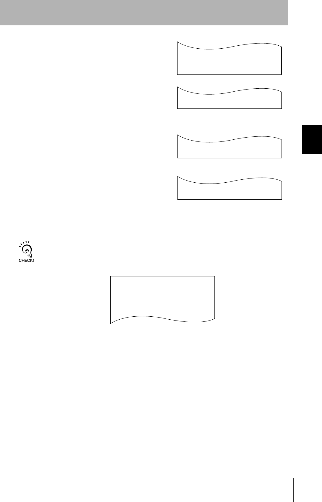
Influence of Background Metal on ID Tag
Metals in the vicinity of the communications area will affect the range, making it smaller.
Refer to page 105.
Influence of Noise
This CIDRW system uses a frequency of 134 kHz for communications with ID Tags. Equipment such
as switching power supplies, inverters, servomotors, or monitors in the surrounding area will adversely
affect communications, restricting the communications area.
The noise levels in the vicinity of the CIDRW Head can be determined with the environmental noise measurement com-
mand (applies only when SECS is not used). Refer to page 82.
For details on the relationship between noise and communications distance, see Appendix. Refer to page 110.
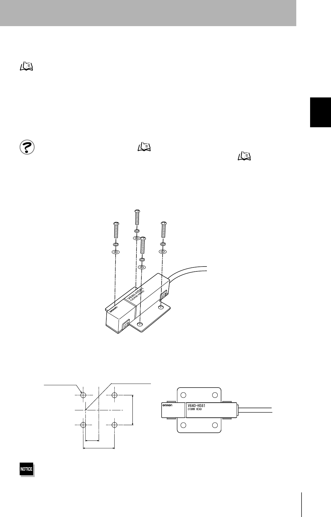
Mounting
Use spring washers and flat washers with the four M3 screws when mounting a CIDRW Head.
Tighten the M3 screws with a torque not exceeding 0.6 N·m.
Be sure to install the Amplifier Unit in a panel or metal-shielded equipment.
r
r
/14Ǿ
Mounting dimensions
(Unit: mm)
Antenna center
26
SECTION 2
Installation
CIDRW System
User’s Manual
SECTION 2
Installation and Connections/Wiring
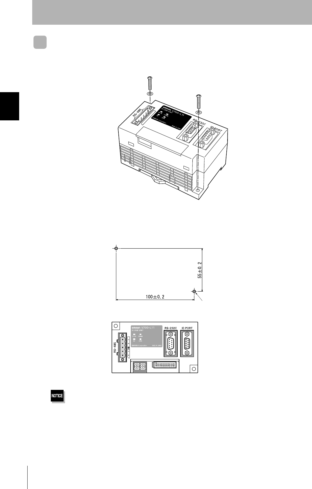
Link Unit
Mount Link Units with the two M4 screws and washers provided as accessories.
•Tighten the M4 screws with a torque not exceeding 1.2 N·m.
• Do not apply organic solvents used with screw locking agents at the locations where the screws are inserted.
Mounting dimensions
(Unit: mm)
Two M4 or 4.2-dia. holes
27
CIDRW System
User’s Manual
SECTION 2
Connections and Wiring
SECTION 2
Installation and Connections/Wiring
Connections and Wiring
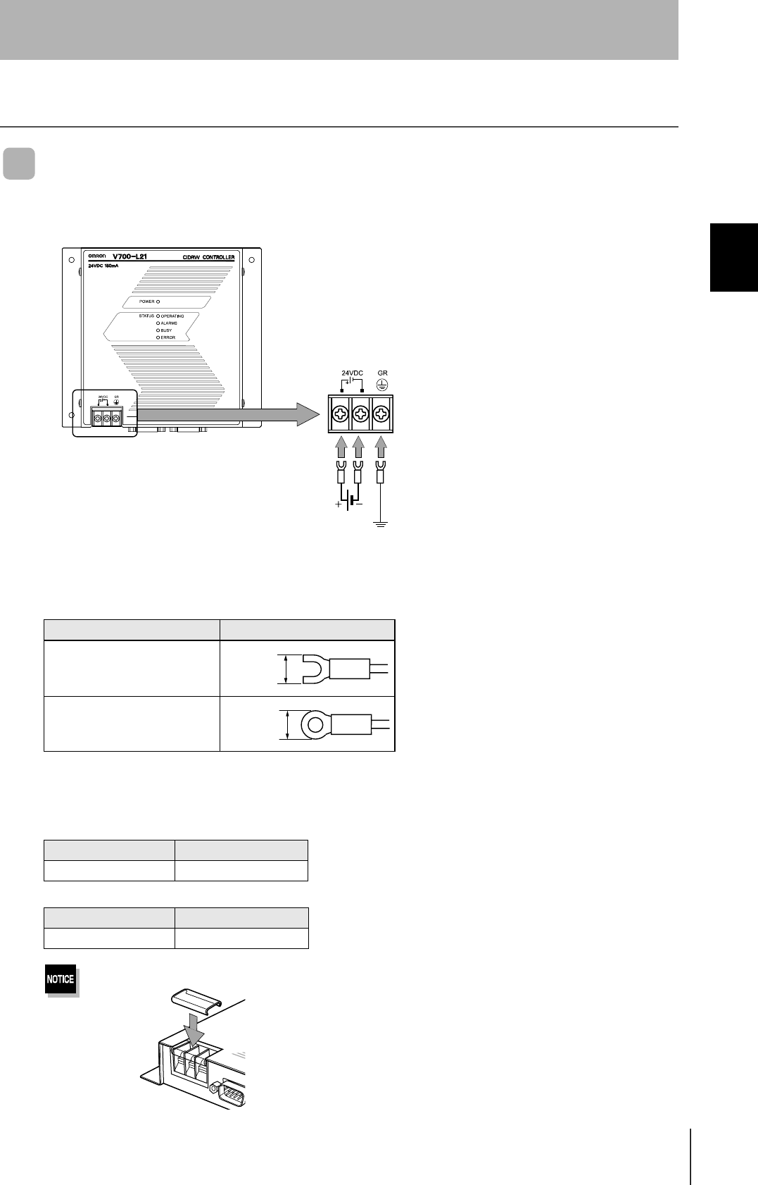
CIDRW Controller
Power Supply and Grounding Wires
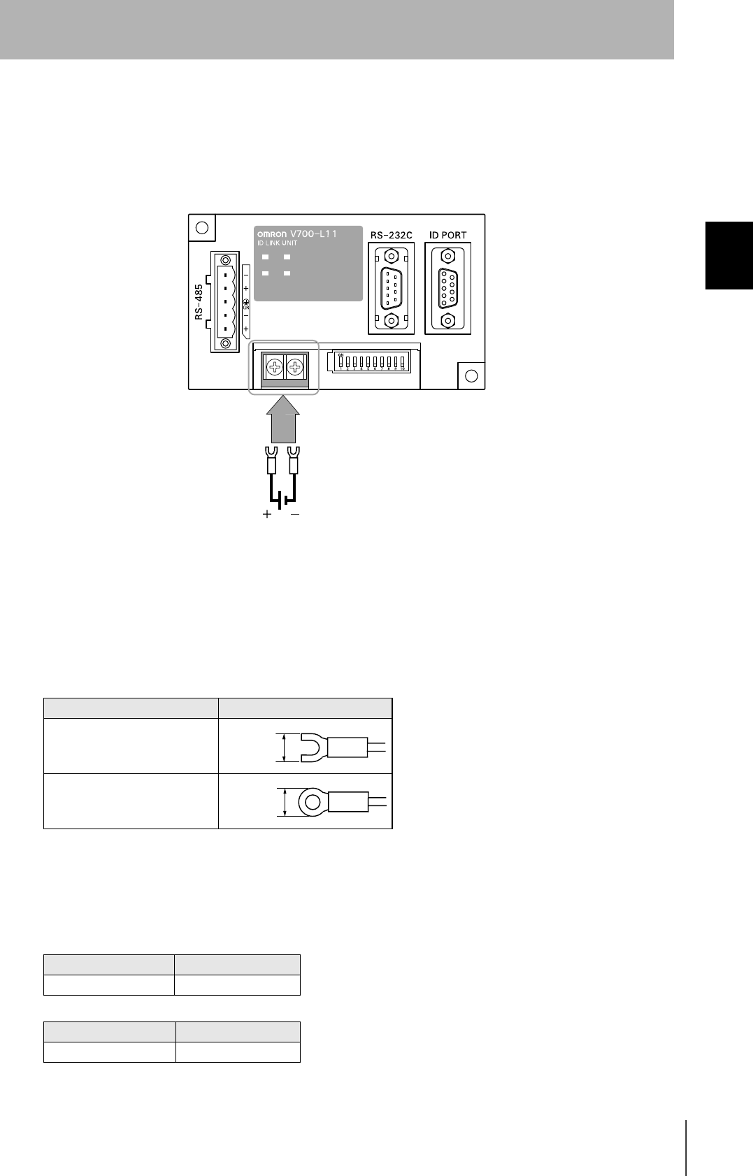
Connect the wires to the 24 VDC power supply terminals and frame ground terminal.
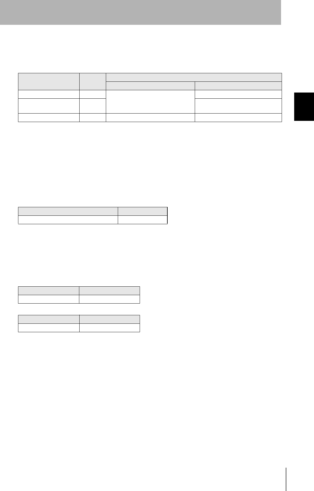
• Crimp terminals
The terminal screws on the terminal block are M3 size. Use appropriate crimp terminals for M3 screws
as shown below.
• Power supply
Use a power supply unit that satisfies the following conditions.
Be sure to replace the cover after wiring.
Crimp terminals
Shape Size
Forked
Round
Condition
Power supply voltage Output current
24 VDC +10%, -15% 500 mA DC min.
Recommended model
Manufacturer Model
OMRON S82K-01524
Ground to 100 Ω or less.
24 VDC
6 mm max.
6 mm max.
28
SECTION 2
Connections and Wiring
CIDRW System
User’s Manual
SECTION 2
Installation and Connections/Wiring
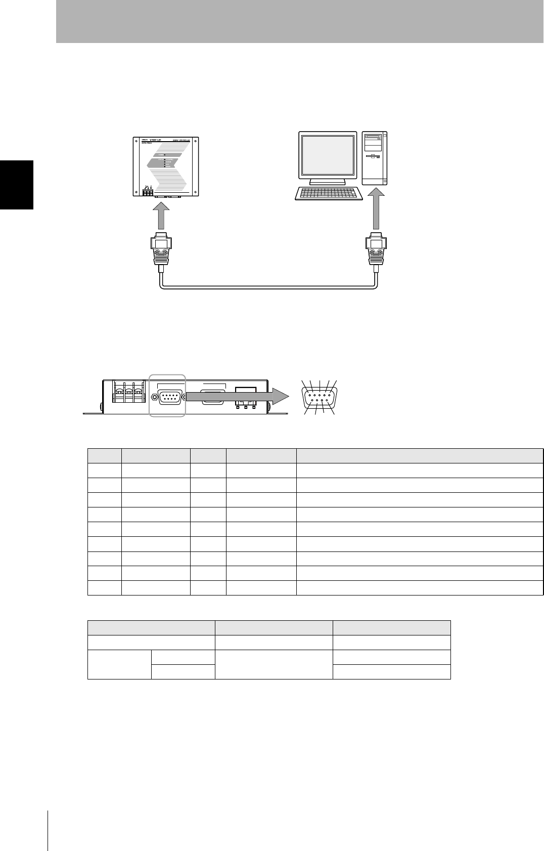
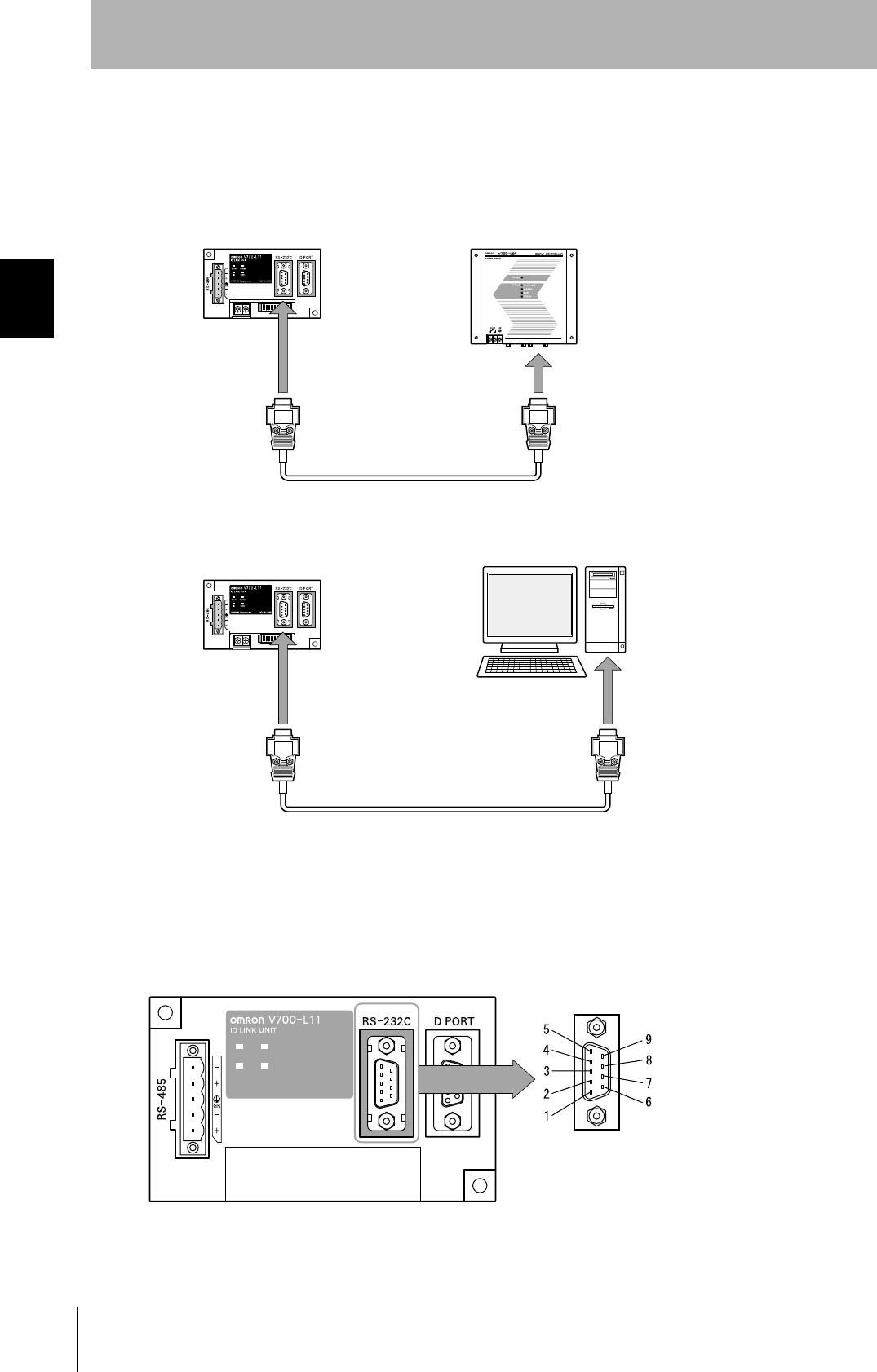
SECS port
The method for wiring for communications with a host device via the SECS port is explained here.
• Connector
The SECS port on the Controller is a D-SUB 9-pin connector. The pin arrangement is shown below.
Recommended model
Pin No. Signal name Symbol Signal direction Remarks
1 — NC — Not connected
2 Receive data RD Input
3 Send data SD Output
4 — — Output Always OFF
5 Signal ground SG —
6 — — Input Use in the "open" status.
7 Request send RS Input Always ON during normal operation
8 — NC — Not connected
9 — NC — Not connected
Manufacturer Model
Cable Hitachi Cable CO-MA-VV-SB 5PX28AWG
Connector Socket OMRON XM2D-0901
Hood XM2S-0913
CIDRW Controller Host
To the RS-232 port
To the SECS port
45%
5'%5 +& /#+06'0#00%'
The connector rim has electrical continuity with the
GR (frame ground) in the 24 VDC power supply ter-
minals.
29
CIDRW System
User’s Manual
SECTION 2
Connections and Wiring
SECTION 2
Installation and Connections/Wiring
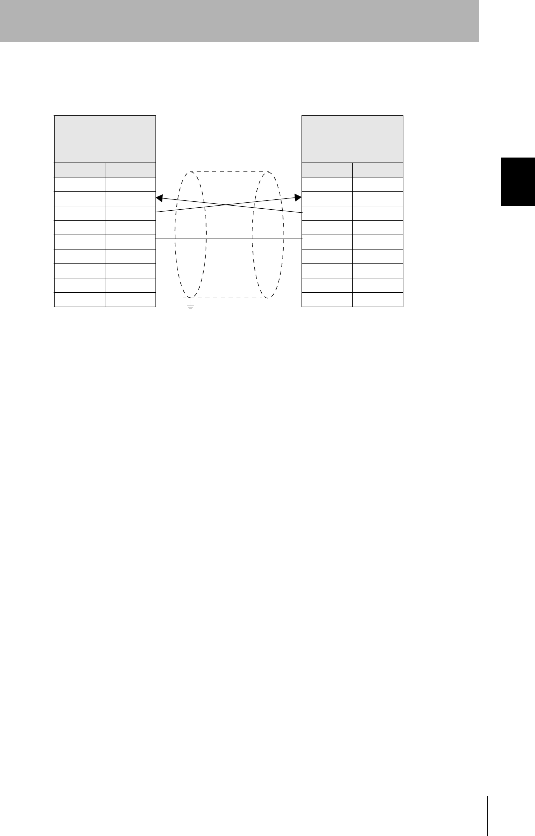
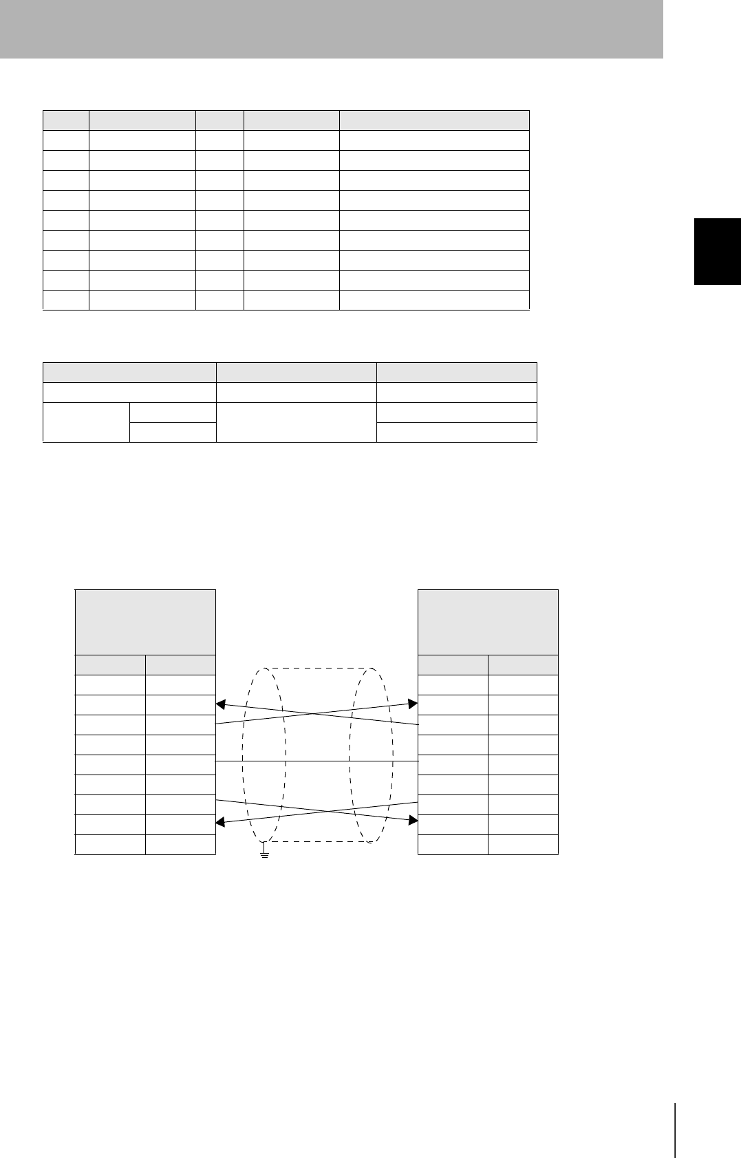
•Wiring
The cable length should be no greater than 15 m.
CIDRW Controller
V700-L21
D-SUB, 9-pin
Socket type #4-40
Name Pin No.
NC 1
RD 2
SD 3
NC 4
SG 5
NC 6
RS 7
NC 8
NC 9
PC/AT Computer
D-SUB, 9-pin
Socket type #4-40
Pin No. Name
1NC
2RD
3SD
4NC
5SG
6NC
7RS
8CS
9NC
Ground shielded wires either at the CIDRW Controller side or at the PC/AT side.
30
SECTION 2
Connections and Wiring
CIDRW System
User’s Manual
SECTION 2
Installation and Connections/Wiring
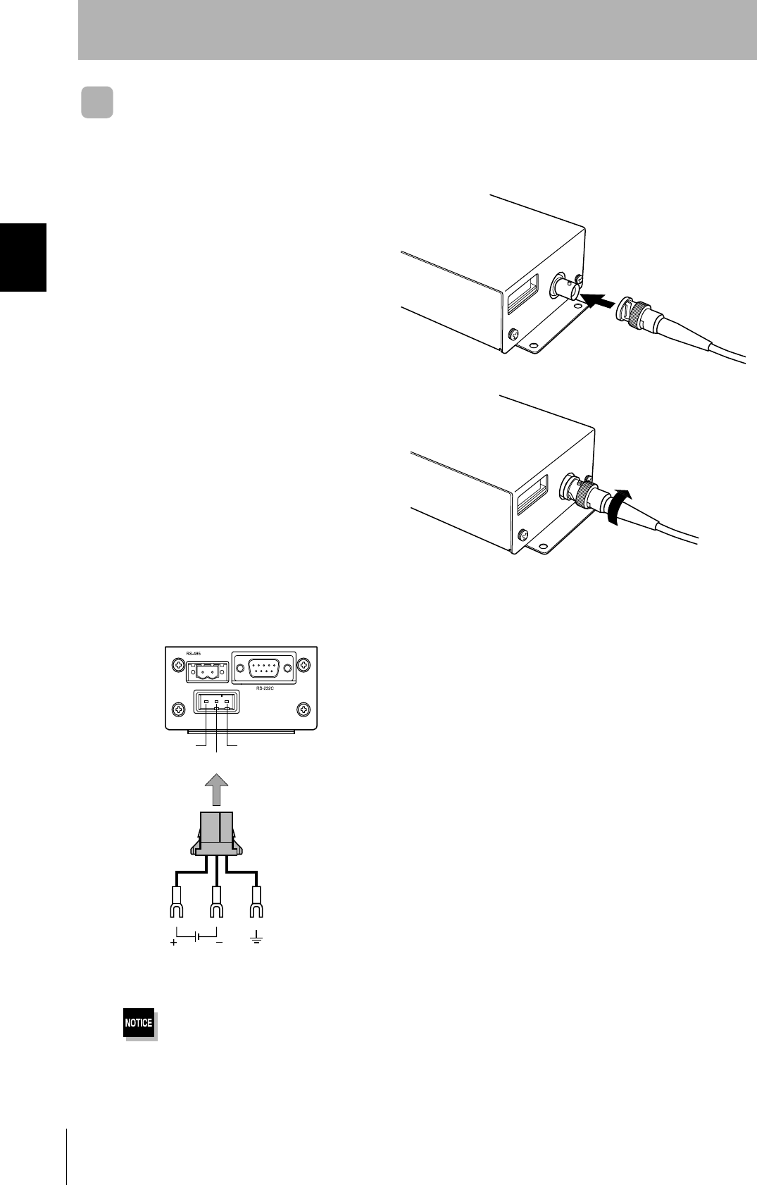
Amplifier Unit
Connector for connecting a CIDRW Head
1. Align the pin on the connector with the
channel in the cable connector and insert
the cable connector.
Hold the fixed part of the connector while making
this insertion.
2. After inserting the connector fully home,
turn the fixed part clockwise to lock it.
Power Supply and Grounding Wires
Connect the power supply and grounding wires to the dedicated power supply connector.
•The grounding wire should be connected to a ground exclusive to the Amplifier Unit. If the grounding wire is shared
with another unit, or connected to a beam in a building, there may be adverse effects.
•Make the grounding point as close as possible and the length of the grounding wire used as short as possible.
24 V+
24 V- GR
24 VDC Ground to 100 Ω or less
Connector
31
CIDRW System
User’s Manual
SECTION 2
Connections and Wiring
SECTION 2
Installation and Connections/Wiring
• Dedicated power supply connector and RS-485 port connector
Prepare a V640-A90 (can be purchased as an accessory).
• Dedicated power supply cable
Use an AWG20 - 24 cable.
Use a dedicated tool for crimping the cable to the connector pins.
• Power supply unit
Use a power supply unit that satisfies the following conditions.
Contents of the V640-A90 set (accessory)
Name Quantity When procured individually
Manufacturer Model
Power supply connector One Tyco Electronics Amp 1-178288-3
Pins for power supply con-
nector
Three 175217-3
Connector for RS-485 port One Phoenix Contact MSTB2.5/2-STF-5.08
Recommended crimping tool
Manufacturer Model
Tyco Electronics Amp 919601-1
Condition
Power supply voltage Output current
24 VDC +10%, -15% 300 mA DC min.
Recommended product
Manufacturer Model
OMRON S82K-01524
32
SECTION 2
Connections and Wiring
CIDRW System
User’s Manual
SECTION 2
Installation and Connections/Wiring
RS-232C Port
The method for connecting a CIDRW Controller or host device via the RS-232C port is explained here.
• Connector
The RS-232C port of the Amplifier Unit is a D-SUB, 9-pin connector. The pin arrangement is shown
below.
Pin No. Signal name Symbol Signal direction Remarks
1 — NC — Not connected
2 Receive data RD Input
3 Send data SD Output
4 — NC — Not connected
5 Signal ground SG —
6 — NC — Not connected
7 Request send RS Output Always ON during normal operation
8 Send enable CS Input
9 — NC — Not connected
Host
To ID port
To the RS-232C port
Amplifier Unit
To the RS-232C port
To the RS-232C port
CIDRW Controller
Amplifier Unit
The connector rim has electrical continuity with the GR (frame
ground) terminal in the dedicated power supply connector.
33
CIDRW System
User’s Manual
SECTION 2
Connections and Wiring
SECTION 2
Installation and Connections/Wiring
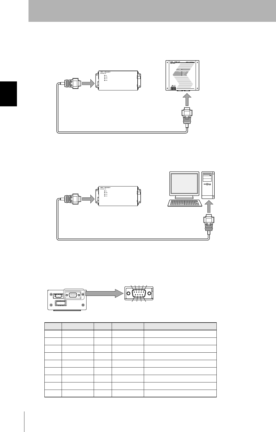
• Wiring for connection to a V700-L21 CIDRW Controller
The cable length should be no greater than 15 m.
Recommended model
Manufacturer Model
Cable Hitachi Cable CO-MA-VV-SB 5PX28AWG
Connector Host side Socket OMRON XM2D-0901
Hood XM2S-0913
Amplifier unit
side
Socket XM2D-0901
Hood XM2S-0911
Amplifier unit
V640-HAM11
D-SUB, 9-pin
Socket type
Metric screw, M2.6
Name Pin No.
NC 1
RD 2
SD 3
NC 4
SG 5
NC 6
RS 7
CS 8
NC 9
CIDRW Controller
V700-L21
D-SUB, 9-pin
Socket type
#4-40
Pin No. Name
1NC
2RD
3SD
4NC
5SG
6NC
7RS
8CS
9NC
Ground shielded wires either at the amplifier unit side or at the
CIDRW side.
34
SECTION 2
Connections and Wiring
CIDRW System
User’s Manual
SECTION 2
Installation and Connections/Wiring
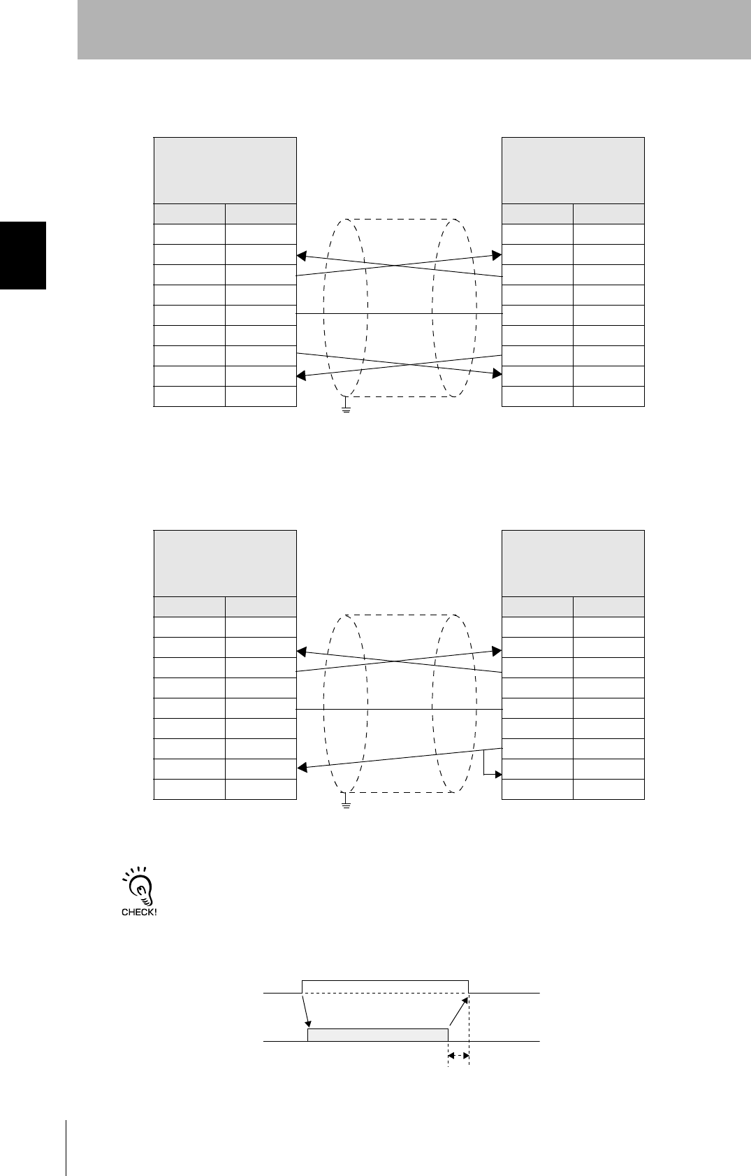
• Wiring for connection to a PC/AT computer (9-pin connector specification)
The cable length should be no greater than 15 m.
If the CS function is to be used at the PC/AT computer side, a return wire is required.
RS signal control method at the host device
In a 1:N connection using Link Units, the RS signals generated from the host device by normal control must be input as
CS signals. Turn the RS signals OFF within 15 ms after the completion of data transmission. Correct communications
will not be possible without this control.
Amplifier unit
V640-HAM11
D-SUB, 9-pin
Socket type
Metric screw, M2.6
Name Pin No.
NC 1
RD 2
SD 3
NC 4
SG 5
NC 6
RS 7
CS 8
NC 9
PC/AT Computer
D-SUB, 9-pin
Socket type
#4-40
Pin No. Name
1NC
2RD
3SD
4NC
5SG
6NC
7RS
8CS
9NC
Ground shielded wires either at the CIDRW Controller side or at the
PC/AT side.
Amplifier unit
V640-HAM11
D-SUB, 9-pin
Socket type
Metric screw, M2.6
Name Pin No.
NC 1
RD 2
SD 3
NC 4
SG 5
NC 6
RS 7
CS 8
NC 9
PC/AT computer
D-SUB, 9-pin
Socket type
#4-40
Pin No. Name
1NC
2RD
3SD
4NC
5SG
6NC
7RS
8CS
9NC
Ground shielded wires either at the CIDRW Controller side or at the
PC/AT side.
SD at host device
RS at host device
ON only during data transmission from the host device
Within 15 ms
35
CIDRW System
User’s Manual
SECTION 2
Connections and Wiring
SECTION 2
Installation and Connections/Wiring
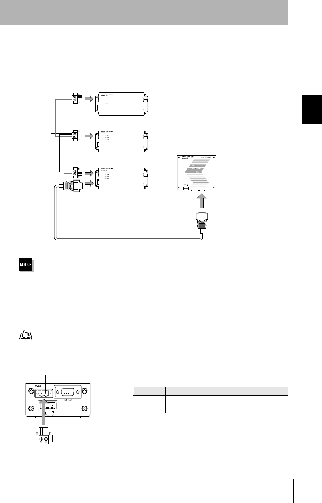
RS-485 Port
The method for connection to the RS-485 port of another Amplifier Unit when multiple CIDRW Heads
are used is explained here.
The maximum total length of RS-485 cable is 50 m.
• Connector
Prepare a V640-A90 (can be purchased as an accessory) as the connector for the RS-485 port on the
Amplifier Unit.
Refer to page 31.
The pin arrangement is shown below.
To the RS-485 port Amplifier Unit
To the RS-232C port
CIDRW Controller
Connector
Name Function
- Connect to the "minus" line of another Amplifier Unit.
+ Connect to the "plus" line of another Amplifier Unit.
-
36
SECTION 2
Connections and Wiring
CIDRW System
User’s Manual
SECTION 2
Installation and Connections/Wiring
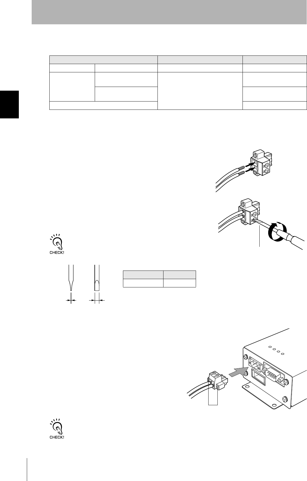
• Notes on cables
•Wiring method
1. Attach crimp terminals to stripped portions of the cables.
2. Insert the wires into the correct holes in the connector, bearing
the orientation of the connector in mind.
3. Tighten the set screws of the connector firmly to secure the
cables.
The appropriate tightening torque is around 0.5 N·m.
A standard, tapered screwdriver will not enter all the way into the
screw holes. Use a small gauge flat-blade screwdriver whose shaft
and tip have the same thickness.
4. Having fitted the connector to the cable, connect it
to an Amplifier Unit.
Orient the cable connector correctly in relation to the connector
on the Amplifier Unit, and fasten the cable connector by fully
tightening the retaining screws.
Disconnecting the connector
Fully loosen the two screws, then grip the projections on the connector and pull it straight out. If it is difficult to pull the
connector out, press down on the Amplifier Unit while pulling on the connector.
Recommended model
Manufacturer Model
Cable RS-485 signal wire Tachii Electric Wire MVVS 2CX0.5SQ
Crimp terminals When one wire is connected
to each terminal.
Phoenix Contact AI0.5-8WH
When two wires are con-
nected to each terminal.
AI-TWIN2×0.5-8WH
Crimping tool CRIMPFOX UD6
Small flat-blade screw-
driver with no taper
Recommended screwdriver
Manufacturer Model
OMRON XW4Z-00C
Side view Face view
0.6 mm 3.5 mm
Set screws
37
CIDRW System
User’s Manual
SECTION 2
Connections and Wiring
SECTION 2
Installation and Connections/Wiring
Link Unit
Power Supply
Opening the cover on the top face of the Link Unit exposes the power supply terminals.
• Crimp terminals
The terminal screws on the terminal block are M3 size. Use appropriate crimp terminals for M3 screws
as shown below.
• Power supply
Use a power supply unit that satisfies the following conditions.
Crimp terminals
Shape Size
Forked
Round
Condition
Power supply voltage Output current
24 VDC +10%, -15% 500 mA DC min.
Recommended model
Manufacturer Model
OMRON S82K-01524
24 VDC
6 mm max.
6 mm max.
38
SECTION 2
Connections and Wiring
CIDRW System
User’s Manual
SECTION 2
Installation and Connections/Wiring
Host Connection Port
The method for connecting to a CIDRW Controller or host device via the RS-232C port is explained
here.
• Connector
The host device connection port on the Link Unit is a D-SUB, 9-pin connector. The pin arrangement is
shown below.
CIDRW Controller
Link Unit
To ID port
To the RS-232C port
To host device port
Link Unit
To host device port
Host
The connector rim does not have electrical
continuity with the GR (frame ground) termi-
nal in the multi-connection port.
39
CIDRW System
User’s Manual
SECTION 2
Connections and Wiring
SECTION 2
Installation and Connections/Wiring
• Wiring for connection to a CIDRW Controller
The cable length should be no greater than 15 m.
Pin No. Signal name Symbol Signal direction Remarks
1 — NC — Not connected
2 Receive data RD Input
3 Send data SD Output
4 — NC — Not connected
5 Signal ground SG —
6 — NC — Not connected
7 Request send RS Output Always ON during normal operation
8 Send enabled CS Input
9 — NC — Not connected
Recommended model
Manufacturer Model
Cable Hitachi Cable CO-MA-VV-SB 5PX28AWG
Connector Socket OMRON XM2D-0901
Hood XM2S-0913
Link unit
V700-L11
D-SUB, 9-pin, female
Socket type #4-40
Name Pin No.
NC 1
RD 2
SD 3
NC 4
SG 5
NC 6
RS 7
CS 8
NC 9
CIDRW Controller
V700-L21
D-SUB, 9-pin, female
Socket type #4-40
Pin No. Name
1NC
2RD
3SD
4NC
5SG
6NC
7RS
8CS
9NC
Ground shielded wires at the CIDRW Controller side.
40
SECTION 2
Connections and Wiring
CIDRW System
User’s Manual
SECTION 2
Installation and Connections/Wiring
• Wiring for connection to a PC/AT computer
If the CS function is to be used at the PC/AT computer side, a return wire is required.
RS signal control method at the host device
In a 1:N system using Link Units, the RS signals generated from the host device by normal control must be input as CS
signals. Turn the RS signals OFF within 15 ms after the completion of data transmission. Correct communications will
not be possible without this control.
Link unit
V700-L11
D-SUB, 9-pin
Socket type #4-40
Name Pin No.
NC 1
RD 2
SD 3
NC 4
SG 5
NC 6
RS 7
CS 8
NC 9
PC/AT Computer
D-SUB, 9-pin
Socket type #4-40
Pin No. Name
1NC
2RD
3SD
4NC
5SG
6NC
7RS
8CS
9NC
Ground shielded wires at the PC/AT computer side.
Link unit
V700-L11
D-SUB, 9-pin
Socket type #4-40
Name Pin No.
NC 1
RD 2
SD 3
NC 4
SG 5
NC 6
RS 7
CS 8
NC 9
PC/AT Computer
D-SUB, 9-pin
Socket type #4-40
Pin No. Name
1NC
2RD
3SD
4NC
5SG
6NC
7RS
8CS
9NC
Ground shielded wires at the PC/AT computer side.
SD at host device
RS at host device
ON only during data transmission from the host device
Within 15 ms
41
CIDRW System
User’s Manual
SECTION 2
Connections and Wiring
SECTION 2
Installation and Connections/Wiring
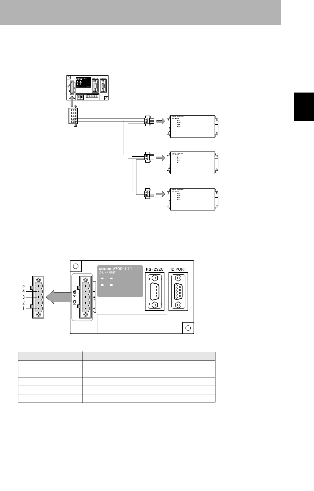
Multi-connection port
The method for connecting to an Amplifier Unit is explained here.
• Connector
Pin No. Name Function
5 - No wiring is required. (Short with terminal 2 within the circuit)
4 + No wiring is required. (Short with terminal 1 within the circuit)
3 GR Ground to 100 Ω or less.
2 - Connect to the "minus" line of the Amplifier Unit.
1 + Connect to the "plus" line of the Amplifier Unit.
Link Unit
Amplifier Unit
To the RS-485 port
To multi-connection port
42
SECTION 2
Connections and Wiring
CIDRW System
User’s Manual
SECTION 2
Installation and Connections/Wiring
•Cable
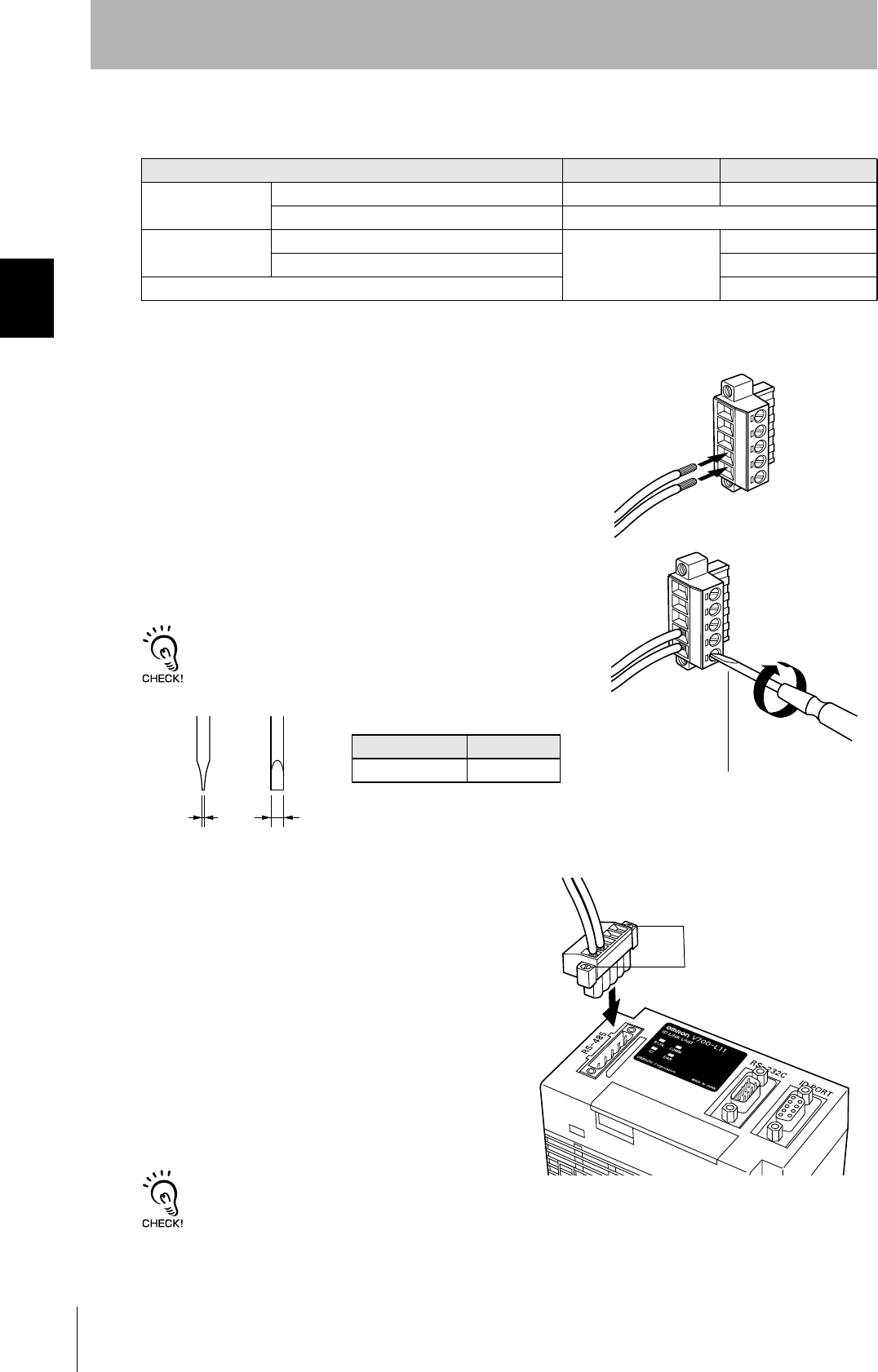
•Wiring method
1. Attach crimp terminals to stripped portions of the cables.
2. Insert the wires into the correct holes in the connector, bearing
the orientation of the connector in mind.
3. Tighten the set screws of the connector firmly to secure the
cables.
The appropriate tightening torque is around 0.5 N·m.
A standard, tapered screwdriver will not enter all the way into the
screw holes. Use a small gauge flat-blade screwdriver whose shaft
and tip have the same thickness.
4. Having fitted the connector to the cable, connect
it to the Link Unit.
Orient the cable connector correctly in relation to the connec-
tor on the Link Unit, and fasten the cable connector by fully
tightening the retaining screws.
Disconnecting the connector
Fully loosen the two screws, then grip the projections on the connector and pull it straight out. If it is difficult to pull the
connector out, press down on the Link Unit while pulling on the connector.
Recommended Product
Manufacturer Model
Cable RS-485 signal wire Tachii Electric Wire MVVS 2CX0.5SQ
Frame ground line AWG22 - 20 cable
Crimp terminals When one wire is connected to each terminal. Phoenix Contact AI0.5-8WH
When two wires are connected to each terminal. AI-TWIN2×0.5-8WH
Crimping tool CRIMPFOX UD6
Small gauge flat-blade
screwdriver with no taper
Recommended screwdriver
Manufacturer Model
OMRON XW4Z-00C
Side view Face view
0.6 mm 3.5 mm
Set screws

44
SECTION 3
Set the Communications Conditions for the CIDRW Controller
CIDRW System
User’s Manual
SECTION 3
Preparing for Communications
Set the Communications Conditions for the CIDRW
Controller
Set the communications conditions of the CIDRW Controller only when SECS is used.
Switch to the Setting mode
The CIDRW Controller has two operating modes, the "Normal Operation mode" and the "Setting
mode."
Switch to the "Setting mode" to set the communications conditions.
There are two methods for switching the mode. Use the one that is appropriate for the circumstances.
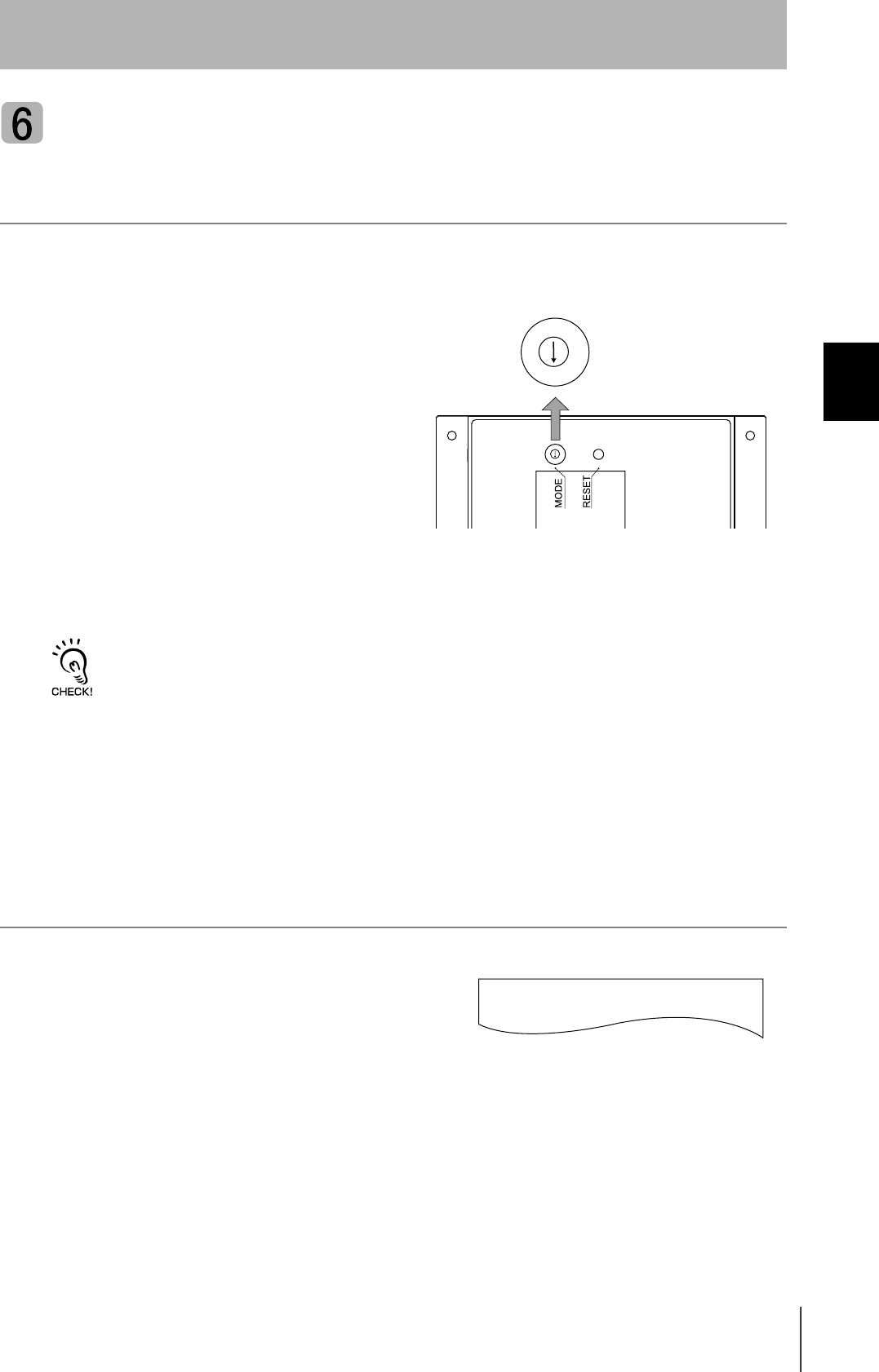
Changing the Position of the Mode Switch on the Bottom of the Unit
This is the convenient method for setting before mounting the unit.
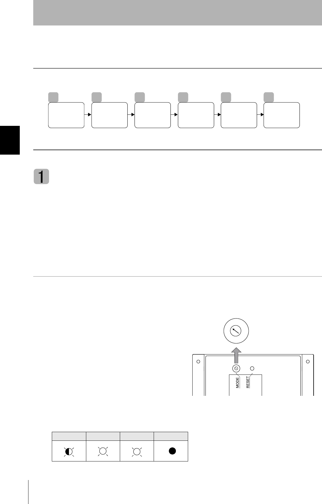
1. Turn OFF the power to the CIDRW Controller.
2. Set the mode switch on the bottom of the unit to
"3."
3. When all of the devices to be used are connected, turn the power ON.
The system starts up in the Setting mode, and the indicators react as shown below.
OPERATING ALARMS BUSY ERROR
1
Switch to the
Setting mode.
2
Start the
terminal
software.
3
Set the
parameters for the
communications
conditions.
4
Change the
Data segment
area.
5
Change the
response
time-out time.
6
Return to the
Normal
Operation
mode.
2
1
0
7
6
5
7
3
2
1
0
7
6
5
7
3
45
CIDRW System
User’s Manual
SECTION 3
Set the Communications Conditions for the CIDRW Controller
SECTION 3
Preparing for Communications
Sending a Switching Command from the Host Device
This method is convenient when the unit has already been mounted and the switch on the bottom can-
not be repositioned to "3."
During operation in the Normal Operation mode, a command is sent from the host device to switch to
the Setting mode.
1. Send a subsystem command (S18F13 ChangeState CPVAL1 = "PS") from the host device.
Refer to page page 70.
CPVAL1="PS" is an expansion designation unique to V700-L21 and does not conform to SEMI standards.
The system is automatically restarted and the mode switches to the Setting mode.
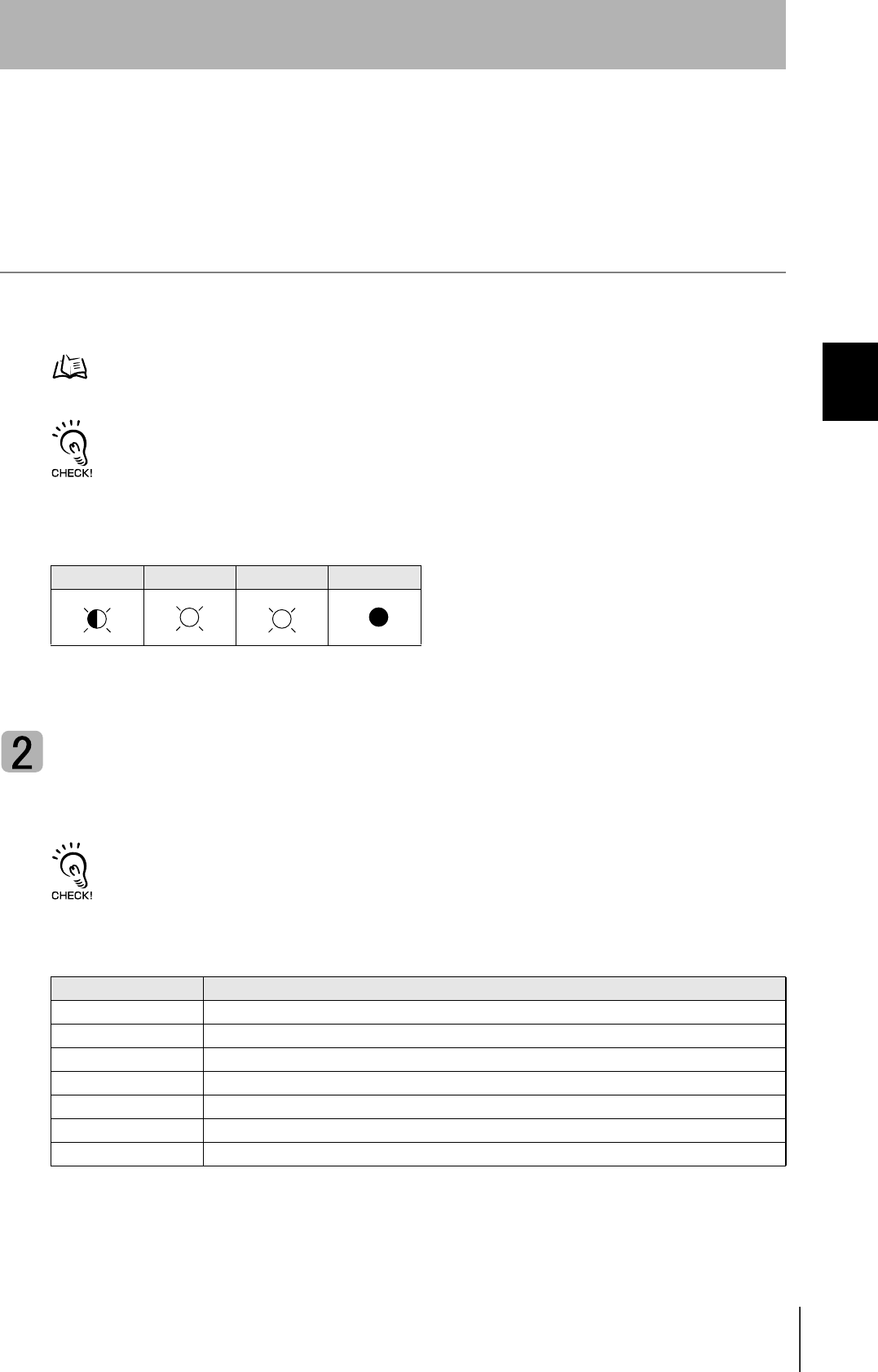
The operation indicators react as shown below.
Start the terminal software
Use the host device's terminal software for the setting.
The commands and communications conditions in the setting mode are unique to OMRON. They do not conform to the
SEMI standards. For the terminal software, use Hyper Terminal, which is standard with Windows, or a similar program.
The communications conditions for communication between the host device and CIDRW Controller
are fixed. Make the following settings using the terminal software.
OPERATING ALARMS BUSY ERROR
Item Setting
Baud rate 9600 bps
Data length 8 bits
Parity EVEN
Stop bit 1
Communications control None
Send code At the end of a line (when [ENTER] is input), the "line feed" characters ([LF]) are appended.
Display Local echo
46
SECTION 3
Set the Communications Conditions for the CIDRW Controller
CIDRW System
User’s Manual
SECTION 3
Preparing for Communications
Set the parameters for the communications conditions
Specify the parameters whose settings are to be changed from the terminal software of the host
device. The commands, and the parameters that can be set are indicated below.
The setting mode commands do not conform to SEMI standards.
For the terminal software, use Hyper Terminal, which is standard with Windows, or a similar program.
List of Commands
Designation Command Input Explanation
Parameter designation (Tag name) = (Set value) <CRLF> Specify the parameter value corresponding to the tag name.
Parameter confirmation ::END Checks the parameter designations that have been received so
far and, if there is no error, confirms the settings.
Comment # (Comment) <CRLF>
or
CRLF
This is ignored as the comment line.
Tag Name List
Classification Parameter Tag name Setting range
Default
setting
Protocol Baud Rate S_BAUD 1200, 2400, 4800, 9600, 19200, 38400, 57600,
115200 bps
9600 bps
Device ID S_DEVID 0 to 32767 0
Time-out between characters S_T1 0.1 to 10 s 0.5 s
Protocol time-out S_T2 0.2 to 25 s 10 s
Response time-out S_T3 1 to 120 s 45 s
Time-out between blocks S_T4 1 to 120 s 45 s
Retry limit S_RTY 0 to 31 3
Master/slave S_MS M : Master
S : Slave
M
SECS Double block detection yes/no S_DB 1: The header of the block currently being
received is compared with the correct block
received immediately before, and double
blocks are detected.
0: Double block detection is not performed.
1
Source ID S_SRC 0 to 32767 0
Single block No. S_BNO 0, 1 1
Operation Baud rate for communications
with Amplifier Unit/Link Unit
C_BAUD 9600, 19200, 38400 bps
Use a consistent baud rate setting within the
same system configuration.
9600 bps
Number of heads count pro-
cessing
C_HEAD 0 to 31
0: The number of heads is automatically
detected at the start. Any increase or
decrease in the number of heads is auto-
matically detected.
1 to 31: The number of heads is specified. The
number of heads detected is compared
with this specified number of heads. If
the number of heads changes, for exam-
ple because a head fails, an error (with
alarm) is detected.
If a head is not connected or an error is
detected with a connected head, so that
the number of heads does not match the
specified number, an error (with alarm) is
detected.
0
47
CIDRW System
User’s Manual
SECTION 3
Set the Communications Conditions for the CIDRW Controller
SECTION 3
Preparing for Communications
1. Specify the parameters to be changed.
When the first parameter is specified, the ALARMS indicator flashes.
2. Confirm the parameter change.
The input parameter is checked and written.
When writing is completed, a message indicating the result is displayed.
The ALARMS indicator lights.
If writing is completed with an error, the parameters are not updated.
The figure in square brackets [ ] indicates the line number where the
error was first detected. If a parity error is detected in the received char-
acters, this figure is [0].
Check the sent data based on this information.
A text file is created based on the data that is keyed in, as shown below, and this data can be conveniently transmitted
using the terminal's text file send function.
S_BAUD=19200
S_DEVID=1
S_BNO=0
_
::END
_
SETUP_COMPLETE
_
SETUP_FAILED [2]_
When writing is completed without error
When writing is completed with an error
#Parameter Setting File for SystemA
#Protocol
S_BAUD=19200
S_DEVID=1
#SECS
S_BNO=0
::END
Example: PRM.TXT
48
SECTION 3
Set the Communications Conditions for the CIDRW Controller
CIDRW System
User’s Manual
SECTION 3
Preparing for Communications
Check for Correct Setting
The currently set data can be output so that you can check if it is correct.
1. Send the parameter output command "::GET_PARAM"
from the host device.
The current communication parameter settings are displayed.
Change the data segment area
The data segment area (memory map) must be changed to communicate with ID Tags (RI-TRP-DR2B,
made by Texas Instruments). The procedure for changing the data segment area is explained here.
Data Segment Area Refer to page 111.
The commands, and the parameters that can be set, are indicated below.
List of Commands
Designation Command input Explanation
Parameter designation (Tag name) = (Set value) <CRLF> Specify the parameter value corresponding to the tag name.
Parameter confirmation ::END Checks the parameter designations that have been received so
far and, if there is no error, confirms the settings.
Comment # (Comment) <CRLF>
or
CRLF
This is ignored as the comment line.
Tag Name List
Parameter Tag name Setting range Default setting
Number of bytes in the carrier ID T_CIDLEN 16 (fixed) 16
Segment name T_SEGN "S01" to "S99" "S01" to "S28"
Number of bytes in a segment T_SEGL 8 (fixed) 8
::GET_PARAM
S_BAUD=19200
S_DEVID=1
S_T1=0.5
S_T2=10.0
S_T3=45
S_T4=3
S_RTY=3
S_MS=M
S_SRC=0
S_BNO=0
C_BAUD=9600
C_HEAD=0
::END
_

49
CIDRW System
User’s Manual
SECTION 3
Set the Communications Conditions for the CIDRW Controller
SECTION 3
Preparing for Communications
1. The form of the input from the host device is shown in the
figure to the right.
When the first parameter is specified, the ALARMS indicator flashes.
2. Confirm the parameter change.
The input parameter is checked and written.
When writing is completed, a message indicating the result is displayed.
The ALARMS indicator lights.
If writing is completed with an error, the parameters are not updated.
The figure in square brackets [ ] indicates the line number where the
error was first detected. If a parity error is detected in the received char-
acters, this figure is [0].
Check the sent data based on this information.
T_CIDLEN=16
T_SEGN=S01
T_SEGL=8
T_SEGN=S02
T_SEGL=8
T_SEGN=S03
T_SEGL=8
T_SEGN=S04
T_SEGL=8
T_SEGN=S05
T_SEGL=8
T_SEGN=S06
T_SEGL=8
T_SEGN=S07
T_SEGL=8
T_SEGN=S08
T_SEGL=8
T_SEGN=S09
T_SEGL=8
T_SEGN=S10
T_SEGL=8
T_SEGN=S11
T_SEGL=8
T_SEGN=S12
T_SEGL=8
T_SEGN=S13
T_SEGL=8
T_SEGN=S14
T_SEGL=8
T_SEGN=S15
T_SEGL=8
_
::END
_
SETUP_COMPLETE
_
SETUP_FAILED [2]_
When writing is completed without error
When writing is completed with an error

50
SECTION 3
Set the Communications Conditions for the CIDRW Controller
CIDRW System
User’s Manual
SECTION 3
Preparing for Communications
Check for Correct Setting
The currently set data can be output so that you can check if it is correct.
1. Send the parameter output command "::GET_SEG" from
the host device.
The data segment area is displayed.
::GET_SEG
T_CIDLEN=16
T_SEGN=S01
T_SEGL=8
T_SEGN=S02
T_SEGL=8
T_SEGN=S03
T_SEGL=8
T_SEGN=S04
T_SEGL=8
T_SEGN=S05
T_SEGL=8
T_SEGN=S06
T_SEGL=8
T_SEGN=S07
T_SEGL=8
T_SEGN=S08
T_SEGL=8
T_SEGN=S09
T_SEGL=8
T_SEGN=S10
T_SEGL=8
T_SEGN=S11
T_SEGL=8
T_SEGN=S12
T_SEGL=8
T_SEGN=S13
T_SEGL=8
T_SEGN=S14
T_SEGL=8
T_SEGN=S15
T_SEGL=8
::END
_

51
CIDRW System
User’s Manual
SECTION 3
Set the Communications Conditions for the CIDRW Controller
SECTION 3
Preparing for Communications
Change the response time-out time
In the initial settings of the CIDRW Controller, when ID Tag (RI-TRP-DR2B, made by Texas Instru-
ments) data is read or written, a "response time-out" may occur. Be sure to set the response time-out
time to "10 s."
The commands, and the parameters that can be set are indicated below.
1. Set the response time-out time to "10.0."
2. Confirm the parameter change.
The input parameter is checked and written.
When writing is completed, a message indicating the result is displayed.
The ALARMS indicator lights.
If writing is completed with an error, the parameters are not updated.
The figure in square brackets [ ] indicates the line number where the
error was first detected. If a parity error is detected in the received char-
acters, this figure is [0].
Check the sent data based on this information.
List of Commands
Designation Command input Explanation
Parameter designation (Tag name) = (Set value) <CRLF> Specify the parameter value corresponding to the tag name.
Parameter confirmation ::END Checks the parameter designations that have been received so
far and, if there is no error, confirms the settings.
Comment # (Comment) <CRLF>
or
CRLF
This is ignored as the comment line.
Tag Name List
Parameter Tag name Setting range Default setting
Response time-out time RT 10.0 (fixed) 2.5
RT=10.0
_
::END
_
SETUP_COMPLETE
_
SETUP_FAILED [2]_
When writing is completed without error
When writing is completed with an error

52
SECTION 3
Set the Communications Conditions for the CIDRW Controller
CIDRW System
User’s Manual
SECTION 3
Preparing for Communications
Check for Correct Setting
The currently set data can be output so that you can check if it is correct.
1. Send the parameter output command "::GET_E99SYS"
from the host device.
The current operation parameter settings are displayed.
Do not change any of the operation parameters apart from RT.
This can cause the system to stop operating correctly.
::GET_E99SYS
RT=10.0
CT=0.1
RTY=3
DINST=
MENT=
MODEL=L21
HREV=001.04
::END
_
53
CIDRW System
User’s Manual
SECTION 3
Set the Communications Conditions for the CIDRW Controller
SECTION 3
Preparing for Communications
Return to the Normal Operation mode
When the Mode is Selected with the Mode Switch on the Bottom of the Unit
1. Turn OFF the power to the CIDRW Controller.
2. Set the mode switch on the bottom of the unit to
the "0."
3. When all of the devices to be used are connected, turn the power ON.
Start up in the Normal Operation mode.
Even if you restart with the mode switch left at the "3" position, or send a reset command "::EXIT," the Controller will
start in the Setting mode. To switch to Normal Operation mode, you must set the mode switch to "0."
When the Mode is Selected by a Command Sent from the Host Device
1. Either send the reset command "::EXIT" from the host
device or turn the power to the CIDRW Controller OFF
and then back ON.
Start up in the Normal Operation mode.
2
1
0
7
6
5
7
3
2
1
0
7
6
5
7
3
::EXIT
_

54
SECTION 3
Set the Communications Conditions for the CIDRW Controller
CIDRW System
User’s Manual
SECTION 3
Preparing for Communications
Reference:
List of Commands
Designation Command input Explanation
Parameter designation (Tag name) = (Set value) <CRLF> Specify the parameter value corresponding to the tag name.
Parameter confirmation ::END Checks the parameter designations that have been received so
far and, if there is no error, confirms the settings.
Comment # (Comment) <CRLF> or CRLF This is ignored as the comment line.
Parameter output ::GET_PARAM Outputs the set parameters (protocol, SECS, operation).
::GET_SEG Outputs the set parameters (ID Tag memory map).
::GET_E99SYS Outputs the set parameters (operations).
RESET :EXIT Restarts the CIDRW Controller.
Tag Name List
Classification Parameter Tag name Setting range Default setting
Protocol Baud Rate S_BAUD 1200, 2400, 4800, 9600, 19200, 38400, 57600,
115200 bps 9600 bps
Device ID S_DEVID 0 to 32767 0
Time-out between
characters S_T1 0.1 to 10 s 0.5 s
Protocol time-out S_T2 0.2 to 25 s 10 s
Response time-out S_T3 1 to 120 s 45 s
Time-out between
blocks S_T4 1 to 120 s 45 s
Retry limit S_RTY 0 to 31 3
Master/slave S_MS M : Master
S : Slave M
SECS Double block detec-
tion yes/no S_DB 1: The header of the block currently being received
is compared with the correct block received
immediately before, and double blocks are
detected.
0: Double block detection is not performed.
1
Source ID S_SRC 0 to 32767 0
Single block No. S_BNO 0, 1 1
Operation Baud rate for com-
munications with
Amplifier Unit/Link
Unit
C_BAUD 9600, 19200, 38400 bps
Use a consistent baud rate setting within the same
system configuration.
9600 bps
Number of heads
count processing C_HEAD 0 to 31
0: The number of heads is automatically
detected at the start. Any increase or
decrease in the number of heads is auto-
matically detected.
1 to 31: The number of heads is specified. The
number of heads detected is compared
with this specified number of heads. If the
number of heads changes, for example
because a head fails, an error (with alarm)
is detected.
If a head is not connected or an error is
detected with a connected head, so that
the number of heads does not match the
specified number, an error (with alarm) is
detected.
0
ID Tag Number of bytes in
the carrier ID T_CIDLEN 16 (fixed) 16
Segment name T_SEGN "S01" - "S99" "S01" - "S28"
Number of bytes in a
segment T_SEGL 8 (fixed) 8
Response time-out time RT 10.0 s (fixed) 2.5 s
55
CIDRW System
User’s Manual
SECTION 3
Set the Communications Conditions for Amplifier Units
SECTION 3
Preparing for Communications
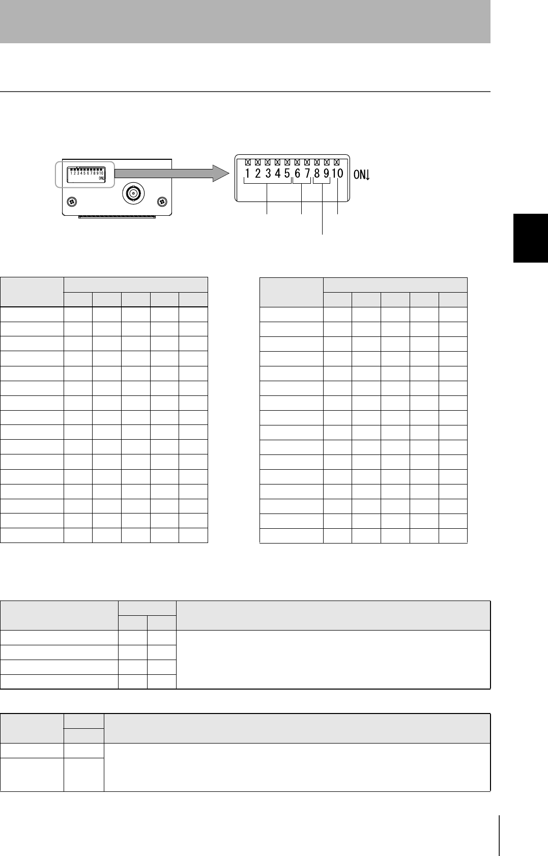
Set the Communications Conditions for Amplifier Units
Set the communications conditions using the DIP switches on the side face of the Amplifier Unit.
After changing the DIP switch settings, restart the system. The new settings will not become effective until the
system is restarted.
Baud rate
Option DIP-SW Description
6 7
38400 bps ON ON Use a consistent baud rate setting within the same system configuration.
19200 bps OFF ON
9600 bps (default setting) OFF OFF
4800 bps ON OFF
RS-485 terminator
Option DIP-SW Description
10
Invalid OFF Set "ON" at both of the end units in a multidrop system, and "OFF" at all the other units. If there is only one
unit, set "ON."
If there is a possibility that one of multiple Amplifier Units in use may be used independently, turn the termi-
nators of all the Amplifier Units OFF and fit external terminators close to the units at both ends.
Valid ON
Node No. Baud rate
Always OFF
(Not used in this CIDRW system)
RS-485 terminator
Node No.
Node No. DIP-SW
1 2 3 4 5
01 OFF OFF OFF OFF OFF
02 ON OFF OFF OFF OFF
03 OFF ON OFF OFF OFF
04 ON ON OFF OFF OFF
05 OFF OFF ON OFF OFF
06 ON OFF ON OFF OFF
07 OFFONONOFFOFF
08 ON ON ON OFF OFF
09 OFF OFF OFF ON OFF
10 ON OFF OFF ON OFF
11 OFF ON OFF ON OFF
12 ON ON OFF ON OFF
13 OFF OFF ON ON OFF
14 ON OFF ON ON OFF
15 OFFONONONOFF
16 ON ON ON ON OFF
Node No. DIP-SW
1 2 3 4 5
17 OFFOFFOFFOFFON
18 ON OFF OFF OFF ON
19 OFF ON OFF OFF ON
20 ON ON OFF OFF ON
21 OFF OFF ON OFF ON
22 ON OFF ON OFF ON
23 OFF ON ON OFF ON
24 ON ON ON OFF ON
25 OFFOFFOFFON ON
26 ON OFF OFF ON ON
27 OFF ON OFF ON ON
28 ON ON OFF ON ON
29 OFF OFF ON ON ON
30 ON OFF ON ON ON
31 OFFONONONON
Setting not possible
ON ON ON ON ON
A
lways set node numbers that are unique within the system configuration. When SECS is used, the node number set here is
"HeadID(E99)."

56
SECTION 3
Set the Communications Conditions for Amplifier Units
CIDRW System
User’s Manual
SECTION 3
Preparing for Communications
Communications conditions
Item Specifications
Standard conformed to RS-232C
Communications con-
trol protocol
1:N protocol exclusive to OMRON
Synchronization
method
Start-stop synchronization
Baud rate Set using a DIP switch
Frame composition Start bit Data bits Parity bit Stop bit Total
1 8 None 1 10
Error detection FCS (frame check sequence)
57
CIDRW System
User’s Manual
SECTION 3
Set the Communications Conditions for Link Units
SECTION 3
Preparing for Communications
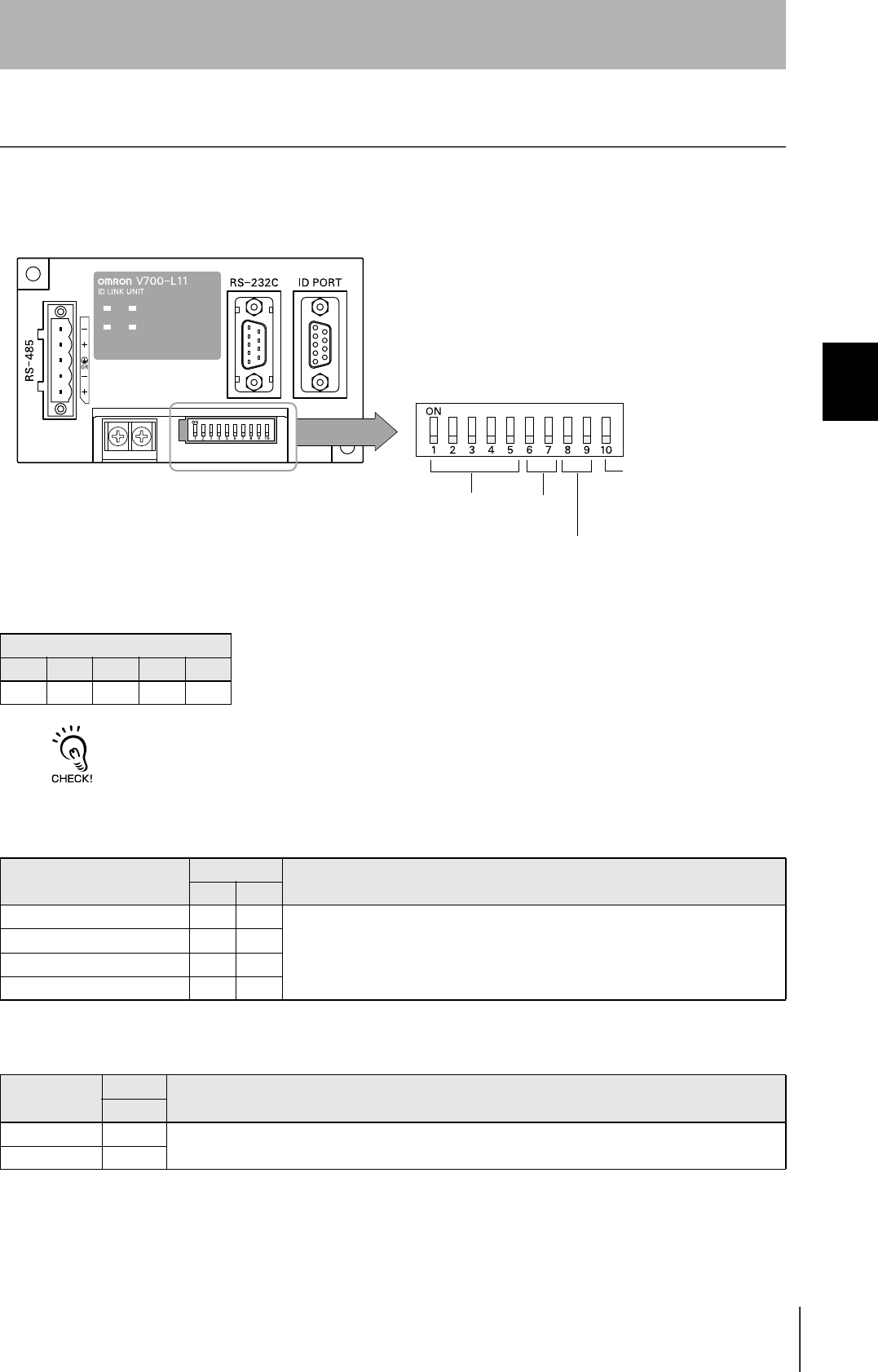
Set the Communications Conditions for Link Units
Set the communications conditions by setting the DIP switches.
The node numbers for Link Units are fixed. Check that DIP switches 1to 5 are all ON.
Node No. (fixed)
DIP-SW
1 2 3 4 5
ON ON ON ON ON
Baud rate
Option DIP-SW Description
6 7
38400 bps ON ON Use a consistent baud rate setting within the same system configuration.
19200 bps OFF ON
9600 bps (default setting) OFF OFF
4800 bps ON OFF
RS-485 terminator
Option DIP-SW Description
10
Invalid OFF Set "ON".
Valid ON
Node No. Baud rate
Always OFF
(Not used in this CIDRW system)
RS-485 terminator

58
SECTION 3
Set the Communications Conditions for Link Units
CIDRW System
User’s Manual
SECTION 3
Preparing for Communications
Communications conditions
Item Specifications
Standard conformed to RS-232C
Communications con-
trol protocol
1:N protocol exclusive to OMRON
Synchronization
method
Start-stop synchronization
Baud rate Set using a DIP switch
Frame composition Start bit Data bits Parity bit Stop bit Total
1 8 None 1 10
Error detection FCS (frame check sequence)
59
CIDRW System
User’s Manual
SECTION 3
Communications Test
SECTION 3
Preparing for Communications
Communications Test
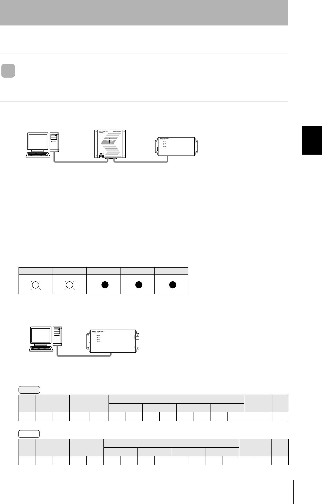
Test for Communications with the Host Device
Check if the host device, CIDRW Controller, and Amplifier Units are correctly connected.
When SECS is Used
• Connection between host device and CIDRW Controller
Send Are You There Request message "S1, F1" from the host device.
If it is correctly connected, On Line Data "S1, F2" will be sent from the CIDRW Controller.
• Connection between the CIDRW Controller and Amplifier Unit
The connection between the CIDRW Controller and Amplifier Unit is checked automatically. If they are
connected correctly, the operation indicators on the CIDRW Controller light in the manner shown
below.
When SECS is Not Used
Node No.1 is tested with the data "12345678."
POWER OPERATING ALARMS BUSY ERROR
SOH Node No. Command code Test data FCS CR
Data 1 Data 2 Data 3 Data 4
01h01 1 0 12345678080Dh
SOH Node No. Response
code
Test data FCS CR
Data 1 Data 2 Data 3 Data 4
01h010012345678090Dh
CIDRW ControllerHost Amplifier Unit
Amplifier UnitHost
Command
Response
60
SECTION 3
Communications Test
CIDRW System
User’s Manual
SECTION 3
Preparing for Communications
ID Tag ↔ CIDRW System Communications Test
Send a command from the host device and check that normal communication with the ID Tag is possi-
ble.
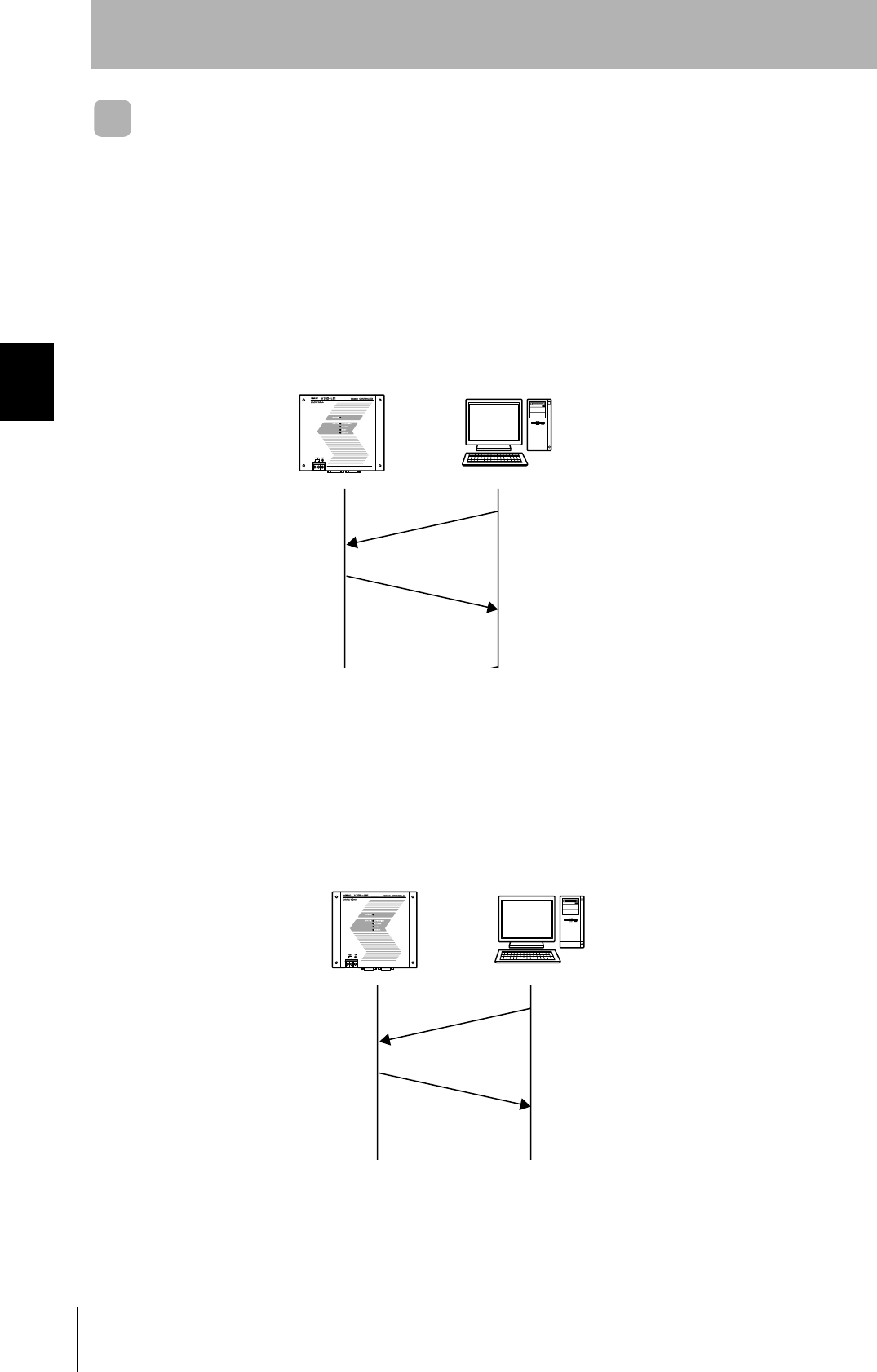
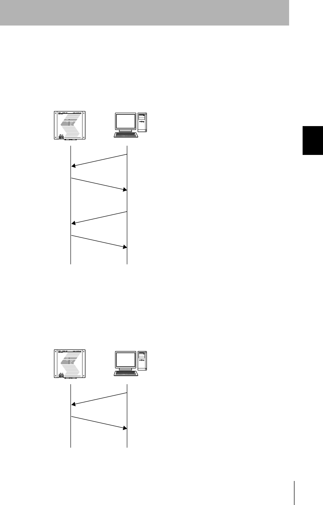
When SECS is Used
• Read ID
The host device sends a Read ID Request message to the CIDRW Controller for Head 1. The CIDRW
Head 1 reads the ID, and the CIDRW Controller returns the ID to the host device.
• Read Data
The host device sends a Read Data Request message to the CIDRW Controller for Head 1, DataSeg
S01 and Datalength 8. The CIDRW Head 1 reads the data, and the CIDRW Controller returns the data
to the host device.
CIDRW Controller Host
S18, F9 Read ID Request
Target ID="01"
S18, F10 Read ID Data
MID="XYZ00001"
CIDRW Controller Host
S18, F5 Read Request
Target ID="01"
Dataseg="S01"
Datalength="8"
S18,F6 Read Data
Data="yyyyyyyy"
61
CIDRW System
User’s Manual
SECTION 3
Communications Test
SECTION 3
Preparing for Communications
• Write ID
(1) The CIDRW Controller is in IDLE. The host device requests the CIDRW Controller change its oper-
ational status to MAINTENANCE.
(2) The CIDRW Controller changes to MAINTENANCE and replies that it has changed state.
(3) The host device sends a Write ID Request message to the CIDRW Controller for Head 1. The
CIDRW Head 1 writes ID, and the CIDRW Controller returns the ID to the host devices.
• Write Data
The host device sends a Write Data Request message to the CIDRW Controller for Head 1 and Data-
Seg S02. The CIDRW Head 1 writes the data, and the CIDRW Controller returns the results to the host
device.
CIDRW Controller Host
S18, F13 SubSystem Command Request
Target ID="01"
CPVAL="MT"
S18, F14 SubSystem Command Acknowledge
SSACK="NO"
S18, F11 Write ID
Target ID="01"
MID="ABC"
S18, F12 Write ID Data
SSACK="NO"
CIDRW Controller Host
S18, F7 Write ID Request
Target ID="01"
Dataseg="S02"
Data="xxxxxx"
S18, F8 Write Data Acknowledge
SSACK="NO"
62
SECTION 3
Communications Test
CIDRW System
User’s Manual
SECTION 3
Preparing for Communications
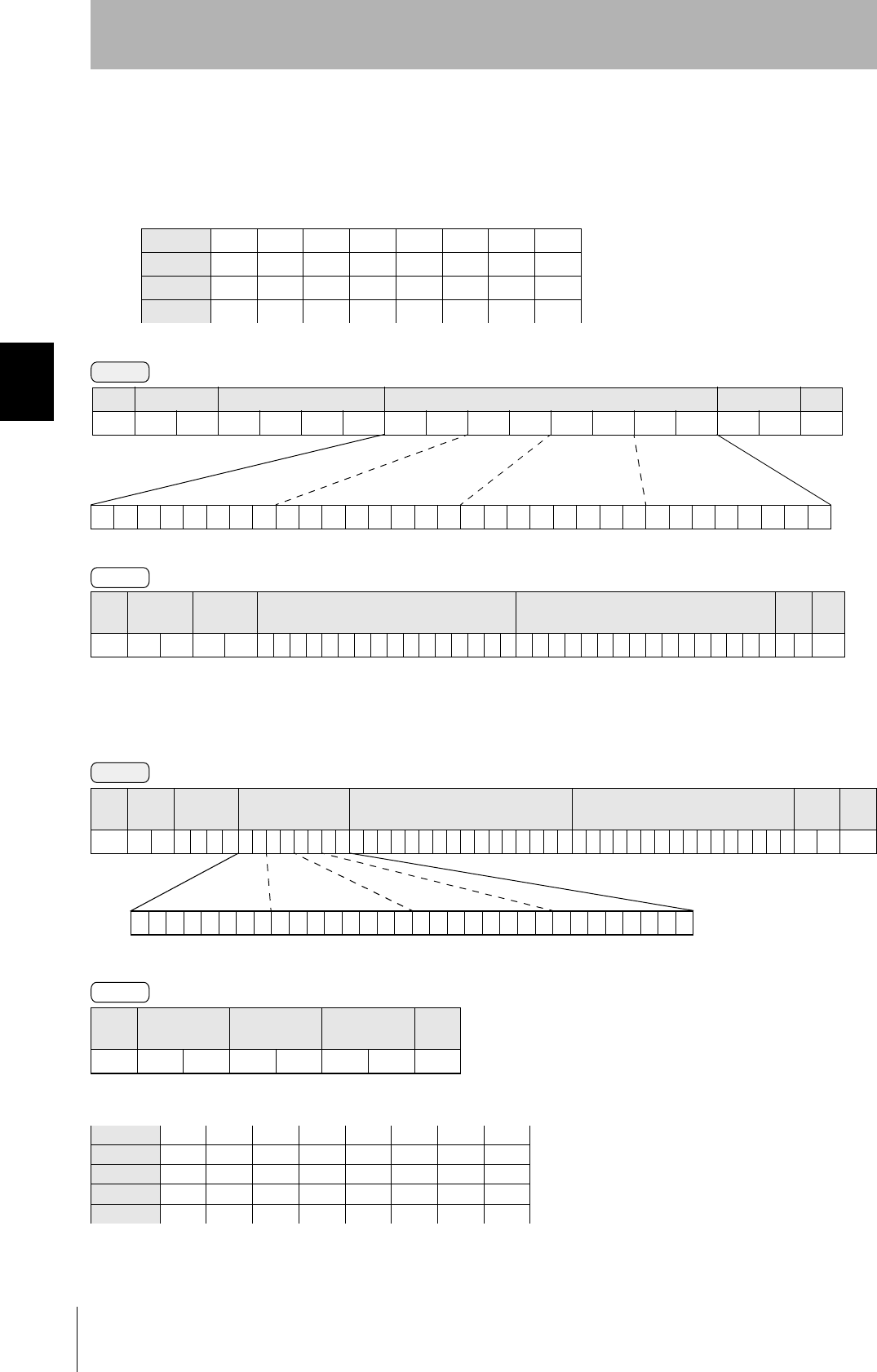
When SECS is Not Used
•Read
Reading the page 1 and page 3 data of node No.1:
•Write
Writing data to page 8 and page 10 of node No.1:
The ID Tag status on normal completion is as shown below:
Data content of the ID Tag
Page 1 12h 34h 56h 78h 90h 12h 34h 56h
Page 2
Page 3 11h 22h 33h 44h 55h 66h 77h 88h
Page 4
SOH Node No. Response
code Page 1 Page 3 FCS CR
01h 0 1 0 0 123456789012345611223344556677880 70Dh
SOH Node No. Response
code FCS CR
01h0100010Dh
Page 8 11h 22h 33h 44h 55h 66h 77h 88h
Page 9
Page 10 01h 23h 45h 67h 89h ABh CDh EFh
Command
00000000000000000000000000010100
Binary notation
SOH Node No. Command code Page designation FCS CR
01h01010000000014050Dh
Response
Command
00000000000000000000101000000000
SOH Node
No.
Command
code Page designation Data of page 8 Data of page 10 FCS CR
01h 0 1 0 2 0 000000A0011223344556677880123456789ABCDEF 7 4 0Dh
Binary notation
Response