Omron 6CYSID4S2V0106 Kanban Reader (RFID system) User Manual users manual
Omron Corporation Kanban Reader (RFID system) users manual
UserManual.wiki
>
Omron
>
6CYSID4S2V0106 User Manual
users manual
Navigation menu
Upload a User Manual
Namespaces
Wiki Guide
HTML
PDF
Info
Views
User Manual
Discussion / Help
Navigation

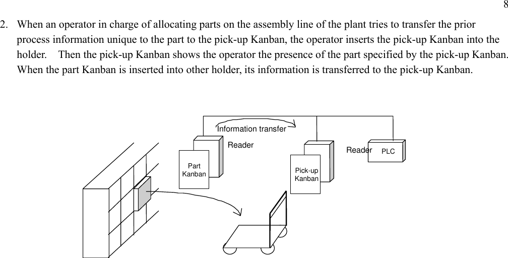
![7 1-2 Example of Use of Kanban Reader Kanban reader Model 4S2VR-V720-KR11 is developed for interfacing between man and equipment for a situation in which reading and writing operation is performed mainly with a device like a Kanban held in a hand. Since a laminate tag significantly varies in communication distance, a close examination should be made when this reader is used in fixed installation. 1. Example of recording information associated with manufacturing (Process equipment number, operator information, time, etc.) in carrying out manufacturing based on Kanban in the manufacturing process. 1.作業者は加工部品が到着すると、その中の作業指示かんばんをかんばんホルダーに差し込む。2.作業者は部品に加工を施し、完成品を加工後のケースに入れる。3.かんばんに加工工程で発生した情報を書き込む。(シリアルNo.、設備No.、所要時間、担当など。 追加で出来高などの情報を付加して入力することもできる。)4.加工が全て完了したら、かんばんをかんばんホルダーから抜いて、加工後のケースにつけて 次工程へ送る。加工前加工後マシニングセンターかんばんリーダかんばんのイメージと、かんばんリーダの状差しイメージは、別紙をご参照ください。 4S2VR-V720KR11Kanban holder Photoelectric switch Junction box Synchronous sensor PS Host[Image of Kanban reader with Kanban holder] Kanban Machining center After machiningBefore machiningKanban reader See the attached paper for the images of Kanban and Kanban holder of the Kanban reader. 1. When parts to be machined arrive, an operator inserts the work instruction Kanban accompanying the parts into the Kanban holder. 2. The operator does machining of the part and puts the finished part into the machined part box. 3. Write information associated with the machining on the Kanban (Serial No., equipment No., required time, person in charge, etc. Additional information such as completed quantity may be included.) 4. When all the machining is complete, withdraw the Kanban from the Kanban holder, and attach it on the case after machining and send it to the next process.](https://usermanual.wiki/Omron/6CYSID4S2V0106/User-Guide-663131-Page-7.png)