Omron 6CYSID4S2V0106 Kanban Reader (RFID system) User Manual users manual
Omron Corporation Kanban Reader (RFID system) users manual
Omron >
users manual

1
Kanban Reader
RFID System
Model 4S2VR-V720-KR11 Series
Operation Manual
Omron Corporation
Extensive Area Sales Department
Information Product Section
March, 2005 Version

2
<Record of Manual Revision>
Jan. 9, 2004 Chapter 1 1-2 Rewriting of example of use
Chapter 2 2-1 Revision of Hoshiden connector type
Chapter 3 3-1 Addition of description of indicator function
Chapter 4 4-1 Revision on time chart
Jan. 13, 2004 Chapter 1 1-2 Rewriting of example of use
Chapter 3 3-1 Revision on system configuration
April 1, 2004 Chapter 2 2-1 Revision on mounting hole
Chapter 4 4-5 Addition of Note
4-7 Addition of Note
Chapter 5 5-2 Correction of description of ADR number in ASCII
April 14, 2004 Chapter 2 2-4 Addition of omitted communication conditions
June 9, 2004 Chapter 2 2-6 Addition of specification of connecting cable
June 28, 2004 Chapter 1 1-2 Rewriting of example of use
Chapter 2 2-1 Addition of outside layout diagram
2-5 Addition of dimensional outline drawing
Chapter 3 3-2 Revision on layout of communication area diagram
Chapter 6 6-4 Addition of omitted description of mutual interference condition
June 30, 2004 P.13 P.17 Revision of typographical errors
July 2, 2004 Chapter 2 2-5 Revision and addition of dimensional outline drawing
July 7, 2004 Chapter 2 2-1 Revision of parts description
2-6-2 Revision of note of cable diagram
July 13, 2004 Chapter 2 Change of item name
July 28, 2004 Chapter 2 2-6-4 Addition of description of shield wire processing
Nov. 10, 2004 Chapter 2 2-2 Revision of general specification, specification, ambient temperature

3
Introduction
Thank you very much for purchasing our Kanban Reader Model 4S2VR-V720-KR11 Series.
Model 4S2VR-V720-KR11 Series is a product developed with advanced technology and accumulated
experiences of Omron.
This Operation Manual includes important information on functions, performance and operating method required
for using Model 4S2VR-V720-KR11 Series.
In operating Model 4S2VR-V720-KR11 Series, observe the following instructions.
• Read and understand this Operation Manual before starting operation.
• Save this Manual with care for future reference.
Notes to Users
When this product is used in the following conditions and environment, care should be used to take safety measures
such as failsafe provision and use with sufficient allowance in rating and performance, and contact sales personnel
of Omron to assure safe and proper operation.
1. Use of the product in conditions and environment not specified in the Operation Manual.
2. Use of the product with equipment for nuclear control, railroad, aviation, vehicle, fuel system, medical
equipment, entertainment devices and safety equipment
3. Use of the product for application which may have a major impact on a human life and property, and
application requiring special safety.
For Safe Operation
Be sure to observe the following instructions to assure safety.
1. Do not use the product in the presence of inflammable, explosive and corrosive gas.
2. Do not attempt to disassemble, repair or remodel the product.
3. Tighten the base securing screws and terminal screws securely.
4. Use crimping terminals of the specified size for wiring.
5. Make sure that a cable or the like having a lock mechanism is securely locked before operation.
6. Ensure that the DC power supply unit meets the following requirements.
1) It should be exclusively used for 4S2VR V720-KR11 and not be connected to other machines and
equipment.
2) The power supply meets the rating of supply voltage (within 5V±5% DC).
7. Observe warnings, cautions and notes included in this manual.
Correct Way to Use
1. Avoid the following places in installing Model 4S2VR V720-KR11.
• Place subjected to direct sunlight
• Place subjected to high humidity and dew condensation
• Place where the main body of the device is subjected to direct vibration and impacts.
2. Prior checking on operating environment
This product uses the frequency band of 13.56MHz and make communications with the tag. The frequency
band of 13.56MHz is also used for the ISM band (One of frequencies assigned to medical equipment and
4
industrial heating devices: Generally an application for approval is required before installation). Consequently,
if such equipment is present nearby, communication with the tag may be affected and the tag may be damaged.
In case that this product is used near such equipment, check the effects of such equipment in advance.
Observe the following instructions so as to minimize the effects of general noises.
• Connect metallic bodies located around this product to Class D grounding (Class 3 grounding).
• Do not install wiring close to high voltage and heavy current.

5
Contents
Chapter 1 Overview of Equipment
1-1 Features
1-2 Example of Use of Kanban Reader
Chapter 2 Specifications
2-1 Part Names and Functions
2-2 General Specifications
2-3 Performance Specifications
2-4 Interface Specifications (RS232C/RS422: To be switched)
2-5 Dimensional Outline Drawing
2-6 Cable Connection Diagram
Chapter 3 Performance
3-1 System Configuration
3-2 Maximum Communication Range
3-3 Communication Time
Chapter 4 Functions
4-1 Procedure of Communication and Outline of Operation
4-2 Memory Map of Tag
4-3 Specification of Access Page
4-4 Specification of Communication Mode
4-5 Types of Commands
4-6 Status
4-7 Exit Code
Chapter 5 Communication Frame
5-1 Overview of Communication Frame
5-2 Command format (When the communication mode with the host is the realtime mode)
5-3 Command format (When the communication mode with the host is the polling mode)
Chapter 6 Cautions in Operation
6-1 Effects of Metal on The Back Face upon Communication Area of Reader
6-2 Effects of Supply Voltage on Communication Area of Reader (For reference)
6-3 Cautions in handling of tag
6-4 Mutual Interference
6-5 Specifications of Tags
6-6 Warranty
6-7 Notice

6
Chapter 1 Overview of Equipment
1-1 Features
1. Model 4S2VR-V720-KR11 allows communication with the tag Model 4S2VR-V720-D13P series (Omron)
which uses Philips' Model SL2ICS20 (known as "I-CODE II").
2. For use with a tag in conformity with ISO15693 standard made by other manufacturer, check on
communication range and others before use.
3. Since Model 4S2VR-V720-KR11 clearly displays responses, it allows checking on the operation of
interfaces with an operator. As a result, this reader is less prone to errors.
4. When Model 4S2VR-V720-KR11 is controlled by the host, up to 16 readers (4S2VR-V720-KR11 ) can be
connected.

7
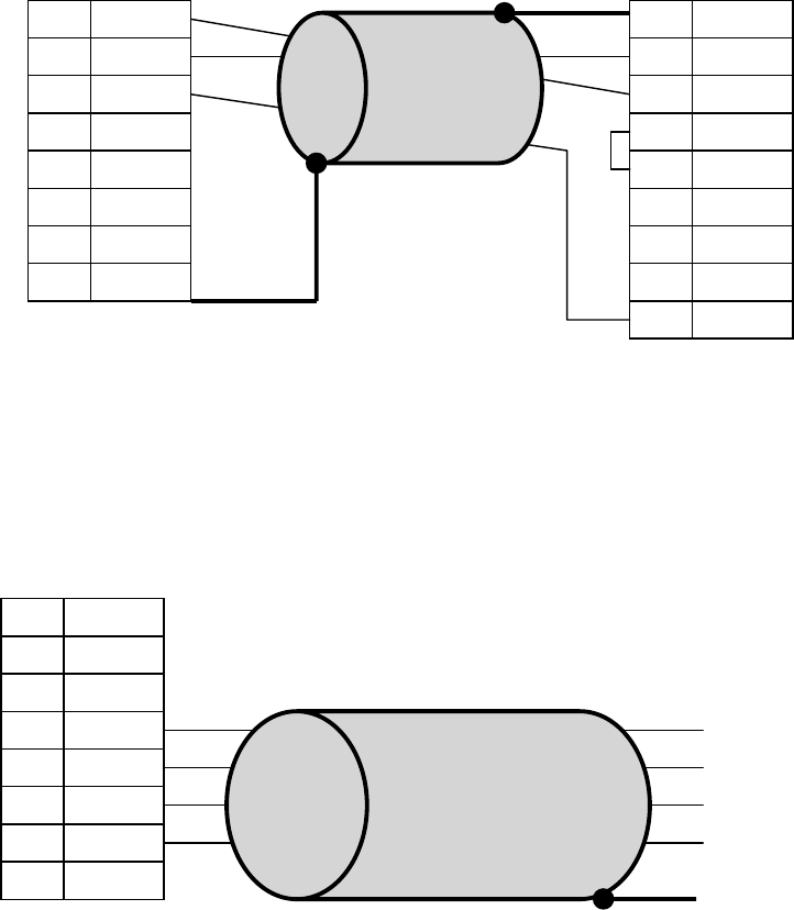
1-2 Example of Use of Kanban Reader
Kanban reader Model 4S2VR-V720-KR11 is developed for interfacing between man and equipment for a
situation in which reading and writing operation is performed mainly with a device like a Kanban held in a hand.
Since a laminate tag significantly varies in communication distance, a close examination should be made when this
reader is used in fixed installation.
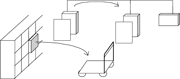
1. Example of recording information associated with manufacturing (Process equipment number, operator
information, time, etc.) in carrying out manufacturing based on Kanban in the manufacturing process.
1.作業者は加工部品が到着すると、その中の作業指示かんばんをかんばんホルダーに差し込む。
2.作業者は部品に加工を施し、完成品を加工後のケースに入れる。
3.かんばんに加工工程で発生した情報を書き込む。(シリアルNo.、設備No.、所要時間、担当など。
追加で出来高などの情報を付加して入力することもできる。)
4.加工が全て完了したら、かんばんをかんばんホルダーから抜いて、加工後のケースにつけて
次工程へ送る。
加工前
加工後
マシニングセンター
かんばんリーダ
かんばんのイメージと、かんばんリーダの
状差しイメージは、別紙をご参照ください。
4S2VR-V720KR11
Kanban holder
Photoelectric switch
Junction box
Synchronous
sensor
PS Host
[Image of Kanban reader with Kanban holder] Kanban
Machining center
A
fter machining
Before machining
Kanban reader
See the attached paper for the images
of Kanban and Kanban holder of the
Kanban reader.
1. When parts to be machined arrive, an operator inserts the work instruction Kanban
accompanying the parts into the Kanban holder.
2. The operator does machining of the part and puts the finished part into the machined part
box.
3. Write information associated with the machining on the Kanban (Serial No., equipment
No., required time, person in charge, etc. Additional information such as completed
quantity may be included.)
4. When all the machining is complete, withdraw the Kanban from the Kanban holder, and
attach it on the case after machining and send it to the next process.
8
2. When an operator in charge of allocating parts on the assembly line of the plant tries to transfer the prior
process information unique to the part to the pick-up Kanban, the operator inserts the pick-up Kanban into the
holder. Then the pick-up Kanban shows the operator the presence of the part specified by the pick-up Kanban.
When the part Kanban is inserted into other holder, its information is transferred to the pick-up Kanban.
PLC
Reader
Part
Kanban
Reader
Pick-up
Kanban
Information transfer
9
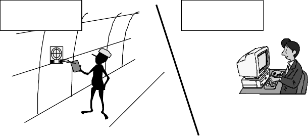
3. Use as a security card or open-close control of gate and door for controlling of entry and exit of people and
vehicles to a controlled area
Underground
tunnel
Computer in
ground-based
station
A
llows controlling where workers are
located.
ÆContributes to efficient worker allocation
as well as improvement in safety.
A Kanban reader is installed for each work section. A person has a Kanban
storing personal data and has the data read by the Kanban reader. A computer
in a ground-based station controls the presence and destination of persons.
Kanban carried by a worker stores personal ID data.
A
lso possible to identify whether the person is allowed
to enter the work area or not.
In this case the card is used as an ID card not as a Kanban.
4. Use as a tag for collecting information of work progress
When an ID tag is incorporated in a Kanban attached to key parts running on the production process,
information can be received and transferred for each process as needed.
At the start of the work, a part Kanban is taken out from the part box and inserted into the Kanban holder of the
Kanban reader. Whe the work is complete, the Kanban is pulled out from the Kanban holder and returned to
the part box as a part Kanban. Information is written in the Kanban tag on the time when the Kanban was
inserted into the Kanban holder and removed from the Kanban holder as well as the number of finished parts in
each process. By performing these operations in all processes, the Kanban collects work records and
man-hour records in all the processes.
5. Use as a barcode reader
• The barcode of a Kanban does not provide reliable reading performance due to smudges on a case.
• In case of a colored kanban, the contrast is low for a barcode reader, thereby resulting in unreliable reading.
• There are a number of problems in reading a barcode on the Kanban including difficulties in setting a
common standard for positioning of a barcode due to various sizes and shapes of a Kanban. A Kanban
incorporating a tag is free from these problems.
10
Chapter 2 Specifications
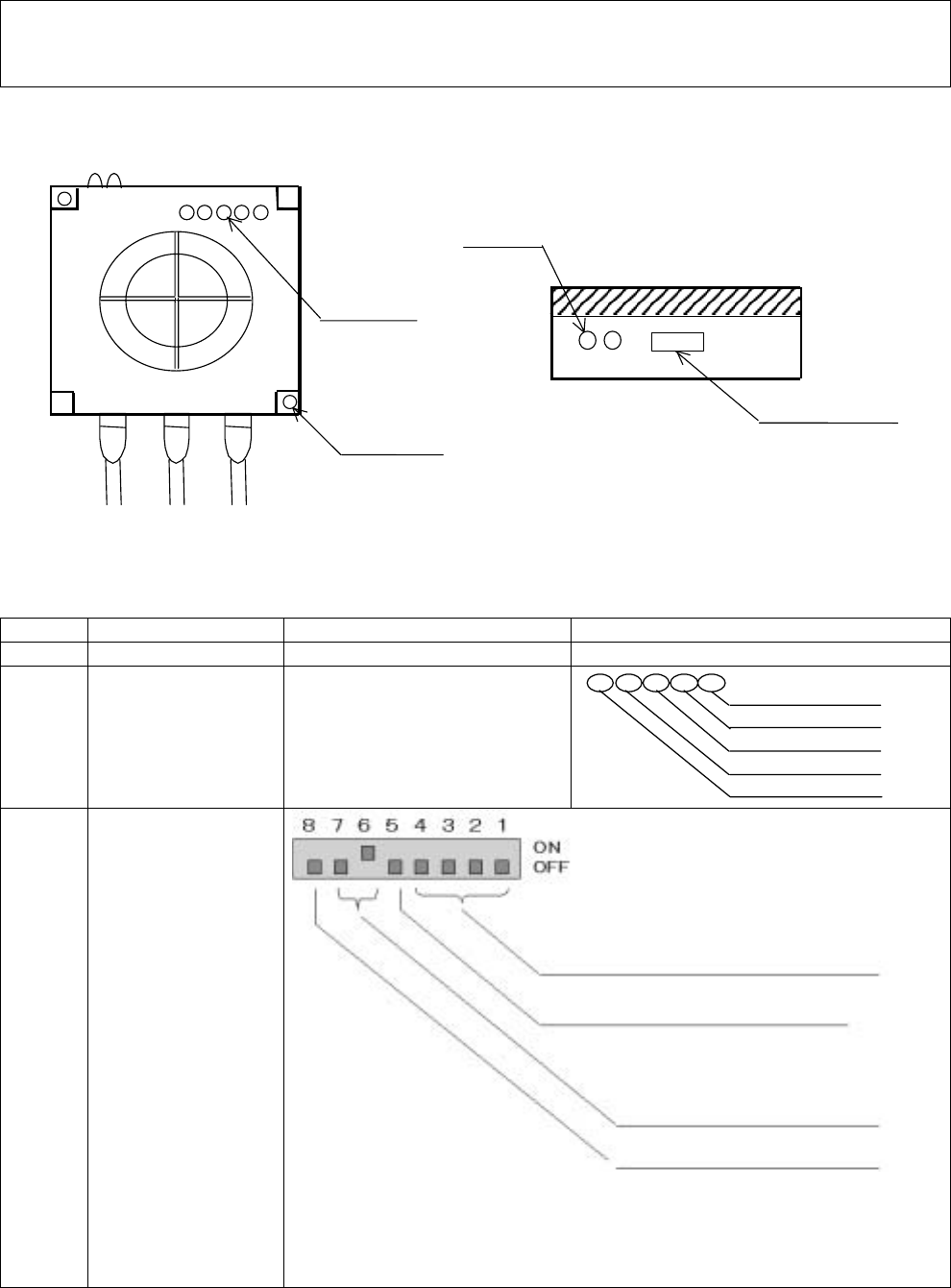
2-1 Part Names and Functions
7) Mounting hole
2) LED display
3) DIP switch
(Front view) (Top view)
1) LED display
(Communication
surface)
NG OK
4) CN1 5) CN2 6) CN3
4S2VR-V720-KR11
RUN T/R EXT OK NG
MADE IN JAPAN
OMRON Corporation
Name Function Description
1) LED display OK/NG judgment display NG (Red)/ OK (Green)
2) LED display Operation display
NG (Red) judgment: No Good
OK (Green) judgment: OK
RUN (Green) power display
T/R (Orange) antenna in operation
EXT (Yellow) external synchronization input
3) DIP switch
Note 4
A
ddress (BIN setup 1: LSB 4: MSB)
System reserved (Normally OFF)
BIT 7/6 = OFF/ON: RS232C
= ON/OFF: RS422
Do not turn on both switches
concurrently.
Setup of RS422 end station
Turn on the reader on the extreme
end alone.
11
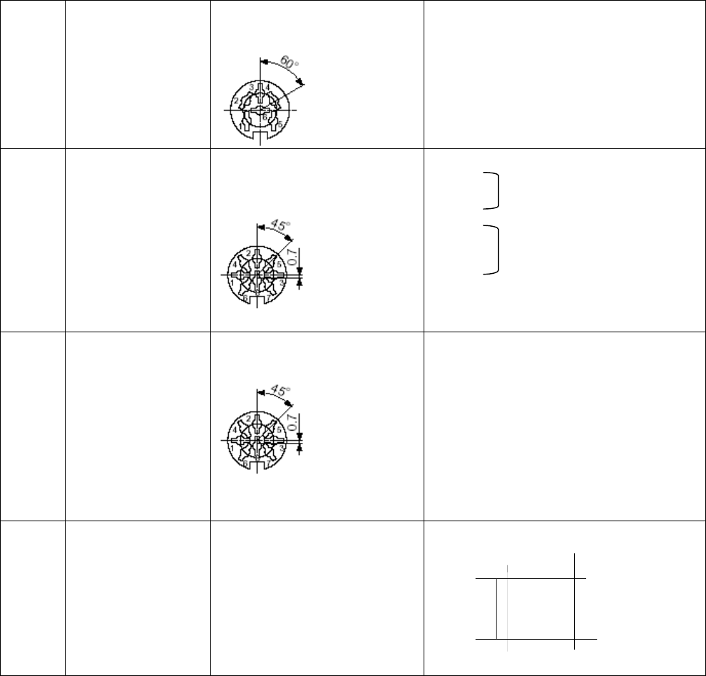
4) CN1 Connector for indicator 6P
Hoshiden type
TCP1366-71-5011
For connection with indicator (option)
1 TXD
2 RXD
3 SG
4 CLK
5 STB
6 KEY
(Connector for display) Notes 4 and 5
5) CN2 Connector for host connection
8P
Hoshiden type
TCP1386-71-5011
Note 1
RS232C/422
1 TXD
2 RXD RS232C
3 SG
4 SD+
5 SD- RS422
6 RD+
7 RD-
8 NC
6) CN3 I/O connector 8P
Hoshiden type
TCP1386-71-5011
Note 1
Power /Synchronizing input /Judgment
output
1 VIN···5V
2 GND···0V
3 NC
4 EXTIN···Trigger input
5 COM+
6 OK
7 NG
8 COM-
Note 2
7) Mounting hole φ4.5 × 2 Machining diagram of mounting hole
Note 1: CN2 and CN3 are same connectors. Use caution not to plug1in mistakenly.
Note 2: See "2-4 External I/O Circuit".
Note 3: Plug connectors of CN1, 2 and 3 are supplied with the product.
Note 4: Seal the DIP switches with the supplied seal after the completion of the initial setup.
Note 5: The indicator is an optional accessory. When the indicator is not used, seal the connector for the
indicator with the supplied seal.
90
90 2-φ4.5
12
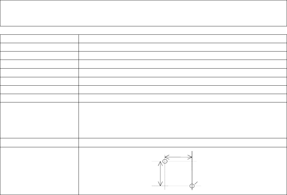
2-2 General Specifications
Item Specifications
Supply voltage 5V±5% (S82K-00705 recommended)*
Consumption current 0.15A
Working ambient temperature -10 - 55°C
Storage ambient temperature -25 - +65°C
Working ambient humidity Working ambient humidity: 25%RH - 85%RH (non-condensing)
Communication frequency 13.56MHz
Weight Approx. 300g
Radio standards Extremely low power radio station (Radio Law, Article 4, Clause 1 "Radio station
emitting extremely low power radio waves specified by the Posts and
Telecommunications Ministry Ordinance"): Electric field intensity of 500µV/m or
less (322MHz or less) at distance of 3m stipulated in the Enforcement Regulation
of Radio Law Article 6, Clause 1
Outline dimensions W100 × H100 × D40
Installation
* Attention should be paid to the voltage drop and noises for the supply power cable. Do not extend the power
cable to longer than 3 m.
90
90 2-
φ
4.5

13
2-3 Performance Specifications
Item Specifications
Communication function Trigger: Communications are made at the time that a command is issued.
Auto: When a command is issued anticipating the approach of the tag,
communication is executed waiting for the approach of a tag.
Continue: When a command is issued, communications with the tag are repeated
until a stop command is received.
Write-protect function: Write-protect setting on the tag can be made. However,
once this setting is made, it cannot be cancelled.
I/O function Judgment output: Output of communication result
Output of judgment of host
Remote synchronization input EXT
Display function
(In planning stage)
Fluorescent display output, 20 digits, 2 lines
Display of command response
Caution!
As a general rule, reading and writing operation of Kanban information by the Kanban reader should be
performed for each Kanban.
When communication is executed with more than one Kanban present within the communication area, a
communication is made with one of the tags or no communication is made at all, causing a tag absence error
and resulting in incorrect information collection.
14
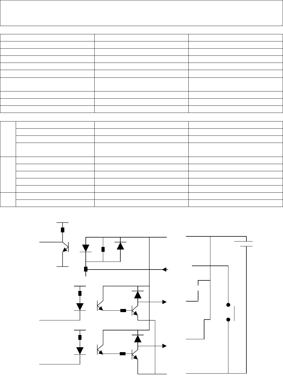
2-4 Interface Specifications (RS232C/RS422: To be switched)
RS232C RS422
Transmission rate 9600bps 9600bps
Data length 8 bit 8 bit
Stop bit 1 bit 1 bit
Synchro system Asynchronous mode Asynchronous mode
Transmission code ASCII ASCII
Maximum number of connectable
controllers 1 16
Error control Parity (Even number) Parity (Even number)
Line length Max 15 m Max 1000 m
Compatible connector TCP1386-71-5011 (Hoshiden) TCP1386-71-5011 (Hoshiden)
Compatible connector TCP1386-71-5011 (Hoshiden) TCP1386-71-5011 (Hoshiden)
Communication method Two-wire system, half-duplex serial Half-duplex serial
Synchro system Asynchronous mode Asynchronous mode
Host
communication
Communication control
method CR control CR control
Compatible connector TCP1386-71-5011 (Hoshiden)
Power supply
EXT
OK
I/O output
NG TCP1366-71-5011 (Hoshiden)
Out
put
<External I/O circuit> <Example of external I/O circuit>
/
/
10K
10K
2.2K
1K
3.3K
1K 3.3K
EXT
COM+
NG
OK
Buzzer or
the like
Buzzer or
the like
24V
-
+
COM-
15
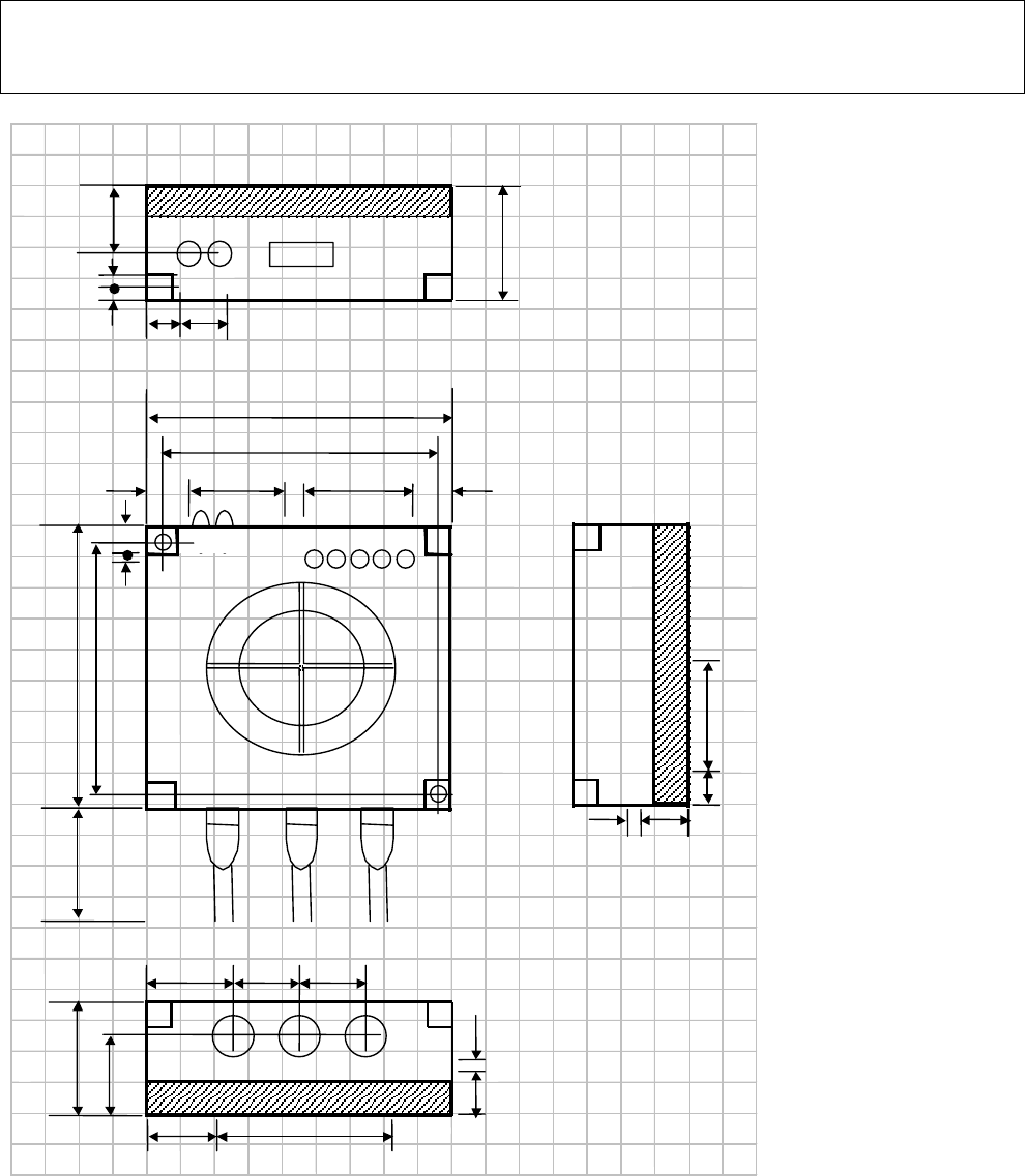
2-5 Dimensional Outline Drawing
2
(Transmission surface)
30
NG OK
40
2 15 12
30
40 DISP COM POWER
27
30 20 20
25 52
4
14
5
10
4S2VR-V720-KR11 RUN T/R EXT OK
OMRON Cor
p
oration MADE IN JAPAN
100
90
(50)
90
100
38
3
43
13
315
10
NO:12Z03-015
16
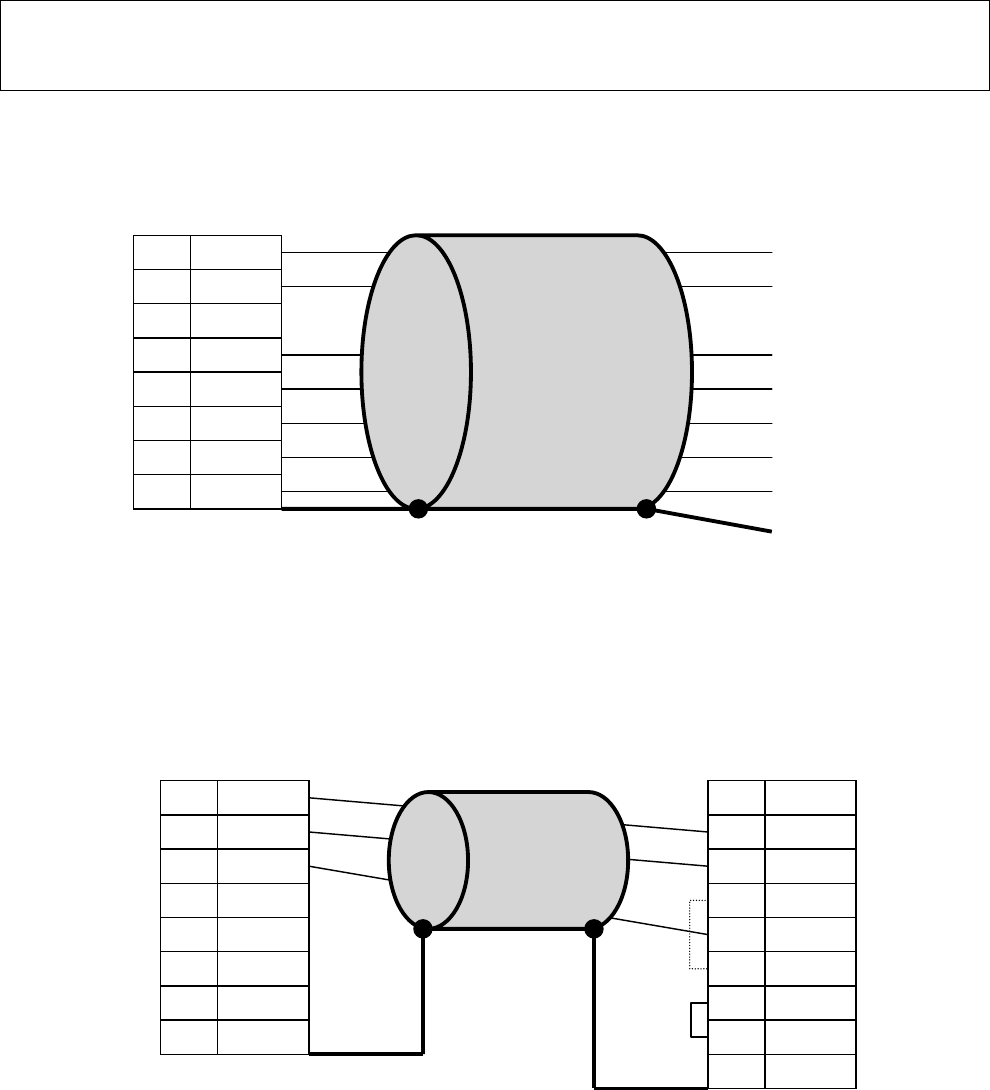
2-6 Cable Connection Diagram
2-6-1 Power cable Model 4S2VR-V720-KRA10
TCP1386-71-5011 (Hoshiden)
2-6-2 RC-232 cable (For PC), Model 4S2VR-V720-KRA21
TCP1386-71-5011 (Hoshiden)
1
2
3
4
5
6
7
8
GND1
-
EXT
O
K
N
G
GND2
Red
Black
Yellow
Brown
Green
White
Blue
Shiel
d
Ground the shield to the metal part
of the connector.
+5V
+24V
1
2
3
4
5
6
7
8
RxD
GND1
SD+
SD‐
RD+
-
RD‐
Ground the shield to the
hood.
Ground the shield to the
metal part of the casing.
TxD 1
2
3
4
5
6
7
8
-
RxD
TxD
GND
DTR
DS
R
CTS
-
9
RTS
Short-circuit
between 4 to 6
and 7 to 8.
17
2-6-3 RC-232C cable (For PLC), Model 4S2VR-V720-KRA41
TCP1386-71-5011 (Hoshiden)
2-6-4 RS-422 cable, Model 4S2VR-V720-KRA31
TCP1386-71-5011 (Hoshiden)
Note 1: Use a pair cable with the (+) and (-) ends of SD and RD paired, respectively.
Note 2: The shield line is not grounded on the Kanban reader side (Model 4S2VR-V720-KR11). Please ground
the shield line on your side.
1
2
3
4
5
6
7
8
RxD
GND1
SD+
SD‐
RD+
-
RD‐
Ground the shield to the
metal part of the casing.
TxD 1
2
3
4
5
6
7
8
FG
SD
RD
CS
RS
5V
ER
SG
9
DR
Short-circuit
between 4 to 5
1
2
3
4
5
6
7
8
RxD
GND1
SD+
SD-
RD+
-
RD-
Black
Black/White
Red
Red/White
18
Chapter 3 Performance
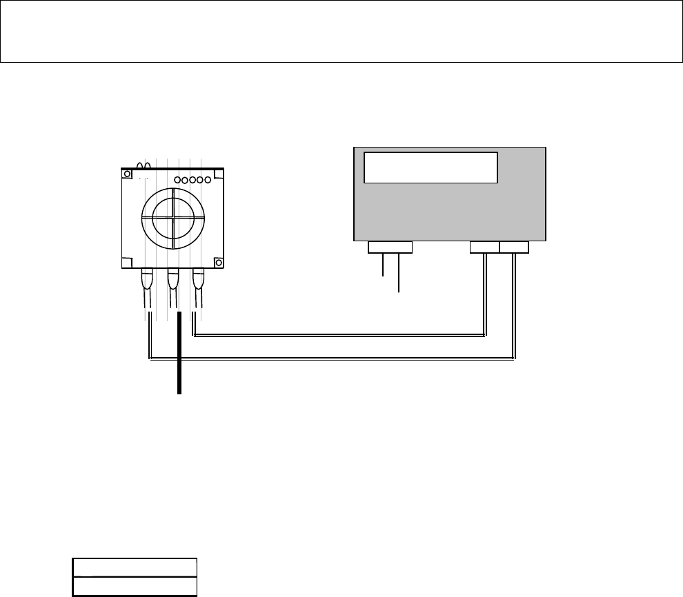
3-1 System Configuration
1. Example of configuration (Basic configuration)
1) A command response is displayed.
C:
R:
2) When information of the Kanban is shown to an operator
3) When the host presents the wok information to an operator based on Kanban data
Terminal block
DISP
W170 × H85 × D35
HOST RS232C/RS422
EXT input
DC24V/
AC100V
Example of display and power box
(In planning stage)
Display in 20 digits by 2 lines
Built-in reader power and display power
Built-in OK/NG buzzer
Calendar, clock and log functions are not
p
rovide
d
EXT
19
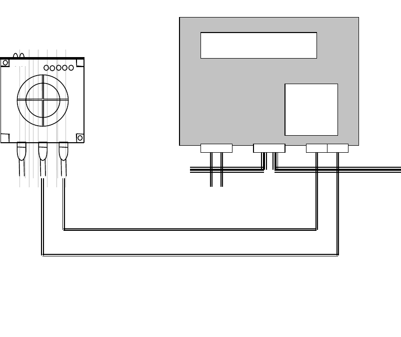
2. Example of configuration (In case of 1 = n connection)
1) The error log of the Kanban reader can be used for maintenance.
2) The same display as shown in the previous section can be presented.
3) Information of numeric keypad can be added to Kanban data to send it up to the host.
4) When the reader reads Kanban information as an independent controller, information can be sent wirelessly
to the host in real time
5) The reader can write the process information on the Kanban as an independent controller.
DC24V/
AC100V
EXT in
p
u
t
W220
×
H110
×
D45
DISP
10KEY
RS422
Example of display and power box (In planning stage)
Built-in CPU board, built-in calendar clock function, built-in data
collection memory
Built-in reader power supply and display power supply, built-in OK/NG
buzzer
20
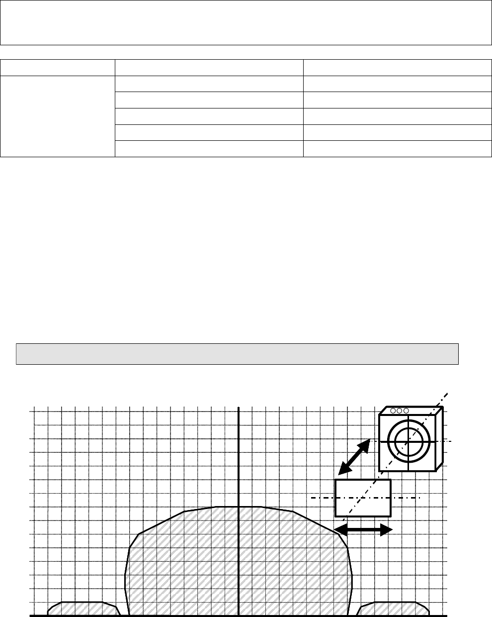
3-2 Maximum Communication Range
Reader Tag Communication range (mm)*
Model 4S2VR-V720-D13P01S 5-20 mm, Axial displacement ±20 mm
Model 4S2VR-V720-D13P01ST 5-20 mm, Axial displacement ±20 mm
Model 4S2VR-V720-D13P30 5-20 mm, Axial displacement ±20 mm
Model 4S2VR-V720-D13P02ST 5-15 mm, Axial displacement ±15 mm
Model 4S2VR-
V720-KR11
Series
Model 4S2VR-V720-D13P06ST 5-15 mm, Axial displacement ±15 mm
* Place the tag in the communication range for communication and do synchronized reading by a synchronization
sensor as much as practical.
* Kanban reader Model 4S2VR is developed for interfacing between man and equipment assuming a situation in
which communications are made with a card-like tag held in a hand. Since the communication distance with a
tag varies, a close examination should be made on the use of this reader in fixed installation.
<Communication range diagram between Kanban reader and tag>
The communication range diagram shown below is given for reference purpose (actual capacity). Use the
Kanban reader within the distance of communication range specified above in actual operation.
Model 4S2VR-V720-KR11 vs Model 4S2VR-V720-D13P01S/01ST/03
010 20
-10 30 40 50 60 70
-
20
-
30
-
40
-
50
-
60
-
70
10
70
60
50
40
30
20
(
mm)
X
Y
X
Y
010 20
-10 30 40 50 60 70
-
20
-
30
-
40
-
50
-
60
-
70
10
70
60
50
40
30
20
(
mm)
X
Y
010 20
-10 30 40 50 60 70
-
20
-
30
-
40
-
50
-
60
-
70
10
70
60
50
40
30
20
(
mm)
X
Y
010 20
-10 30 40 50 60 70
-
20
-
30
-
40
-
50
-
60
-
70
10
70
60
50
40
30
20
(
mm)
X
Y
X
Y
X
Y
X
Y