Omron V640HAM11 Carrier ID Reader/Writer (RFID) User Manual Z307 E1 01
Omron Corporation Carrier ID Reader/Writer (RFID) Z307 E1 01
Omron >
Contents
- 1. User manual(ETN)
- 2. User manual(V3)
- 3. User manual2& 65288;ETN)
- 4. User manual2& 65288;V3)
User manual2& 65288;V3)

SECTION 4
Reading from/Writing to ID Tags
69
CIDRW System
User’s Manual
SECTION 4
Reading from/Writing to ID Tags
When SECS Is Used 70
Online Check 72
Get Attributes 72
Set Attributes 73
Read Data 74
Write Data 75
Read ID 76
Write ID 76
Subsystem Command (ChangeState) 77
Subsystem Command (GetStatus) 78
Subsystem Command (PerformDiagnostics) 78
Subsystem Command (Reset) 79
When SECS Is Not Used 81
READ 84
WRITE 85
SAME WRITE 87
BYTE WRITE 88
TEST 89
NAK 90
GET PARAMETER 90
GET LAST COMMAND 92
GET COMMUNICATIONS HISTORY 93
CLEAR COMMUNICATIONS HISTORY 94
NOISE MEASUREMENT 94
RESET 94
70
SECTION 4
When SECS Is Used
CIDRW System
User’s Manual
SECTION 4
Reading from/Writing to ID Tags
When SECS Is Used
The SEMI standards are subject to revision. You must refer to the actual standards.
• SEMI E99 THE CARRIER ID READER/WRITER FUNCTIONAL STANDARD
• SEMI E5 EQUIPMENT COMMUNICATION STANDARD 2 MESSAGE CONTENT (SECS II)
• SEMI E4 EQUIPMENT COMMUNICATION STANDARD 1 MESSAGE TRANSFER (SECS I)
SECS Protocol Specifications Refer to page 149.
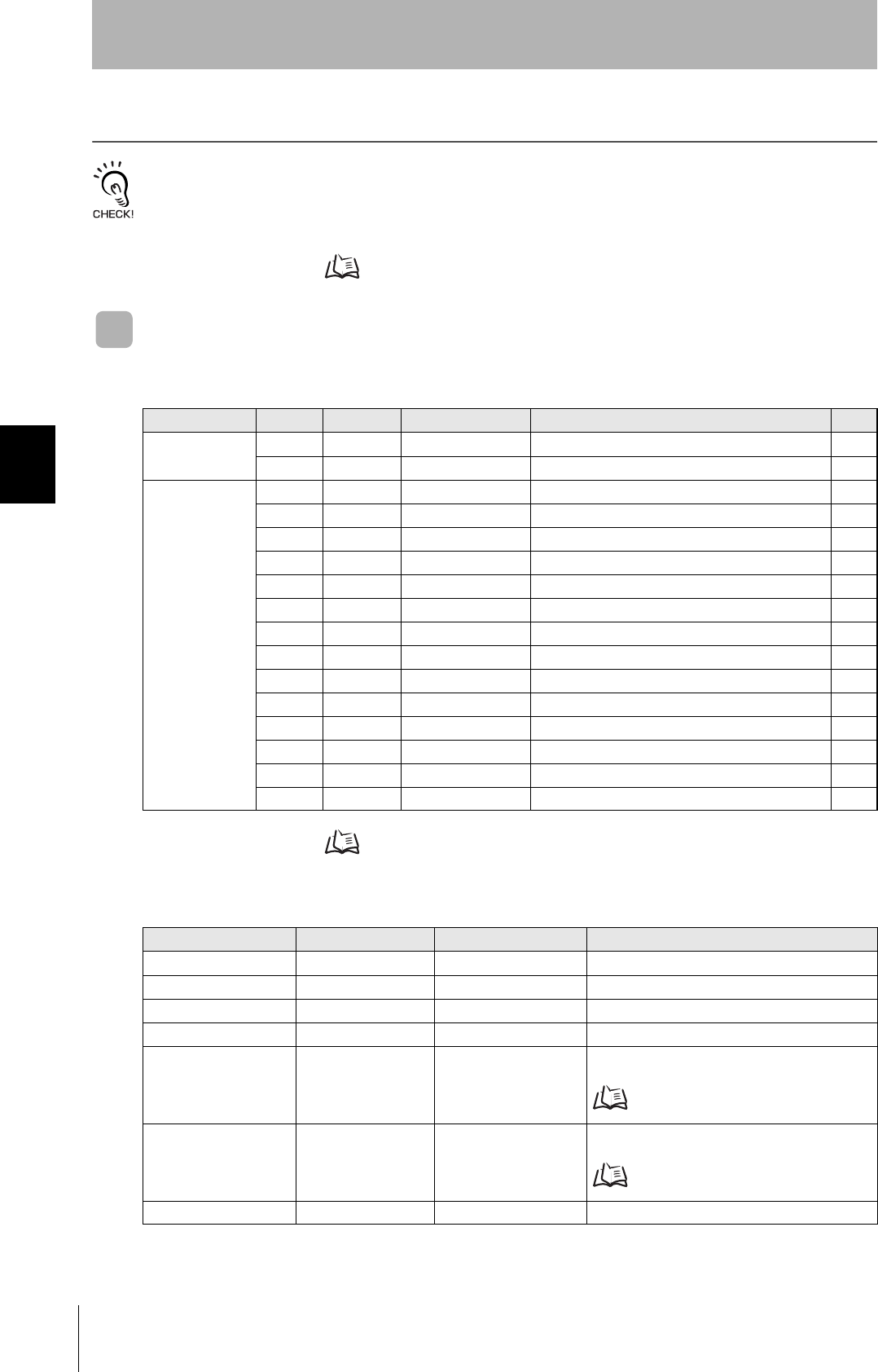
Message Specifications
List of Error Messages Refer to page 96.
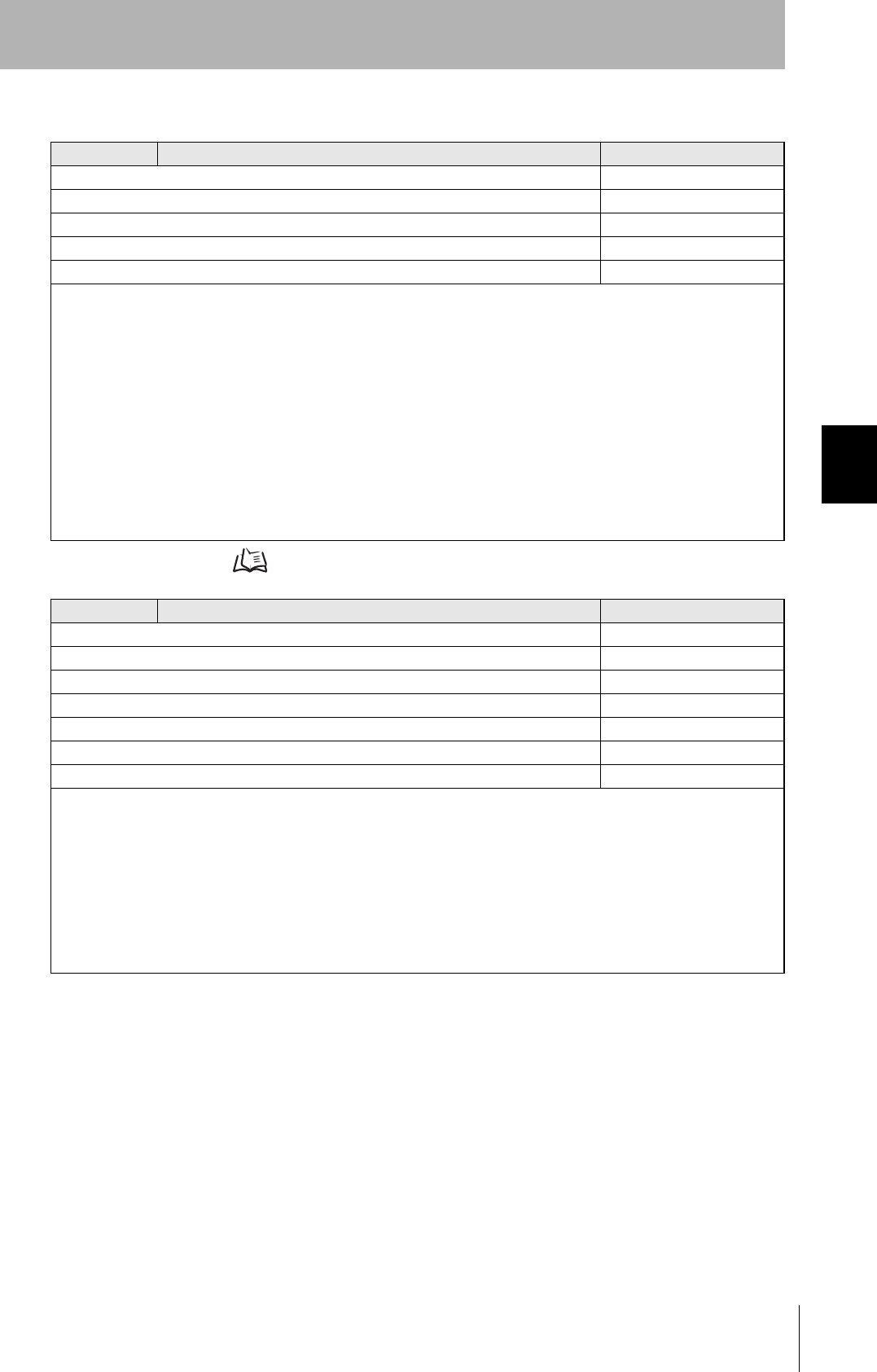
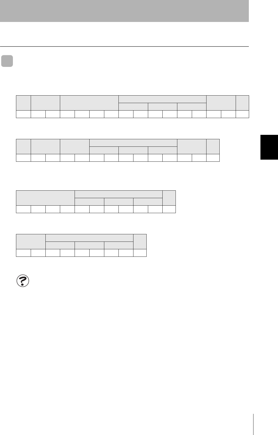
List of Messages Used
Classification S F Direction SECS II names See
General purpose
messages
11 S,H→E,reply Are You There Request p.72
12 S,H←E On Line Data p.72
CIDRW system
messages
18 1 S,H→E,reply Read Attribute Request p.72
18 2 S,H←E Read Attribute Data p.72
18 3 S,H→E,reply Write Attribute Request p.73
18 4 S,H←E Write Attribute Acknowledge p.73
18 5 S,H→E,reply Read Request p.74
18 6 S,H←E Read Data p.74
18 7 S,H→E,reply Write Request p.75
18 8 S,H←E Write Acknowledge p.75
18 9 S,H→E,reply Read ID Request p.76
18 10 S,H←E Read ID Data p.76
18 11 S,H→E,reply Write ID Request p.76
18 12 S,H←E Write ID Acknowledge p.76
18 13 S,H→E,reply Subsystem Command Request p.77
18 14 S,H←E Subsystem Command Acknowledge p.77
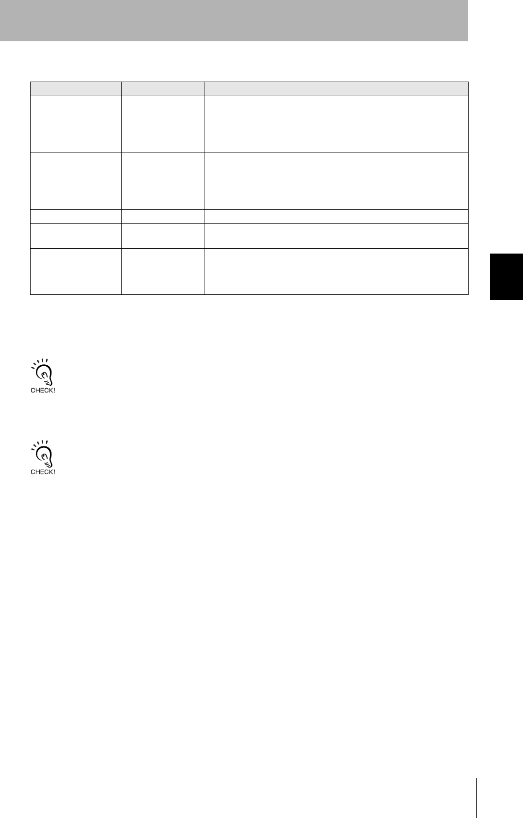
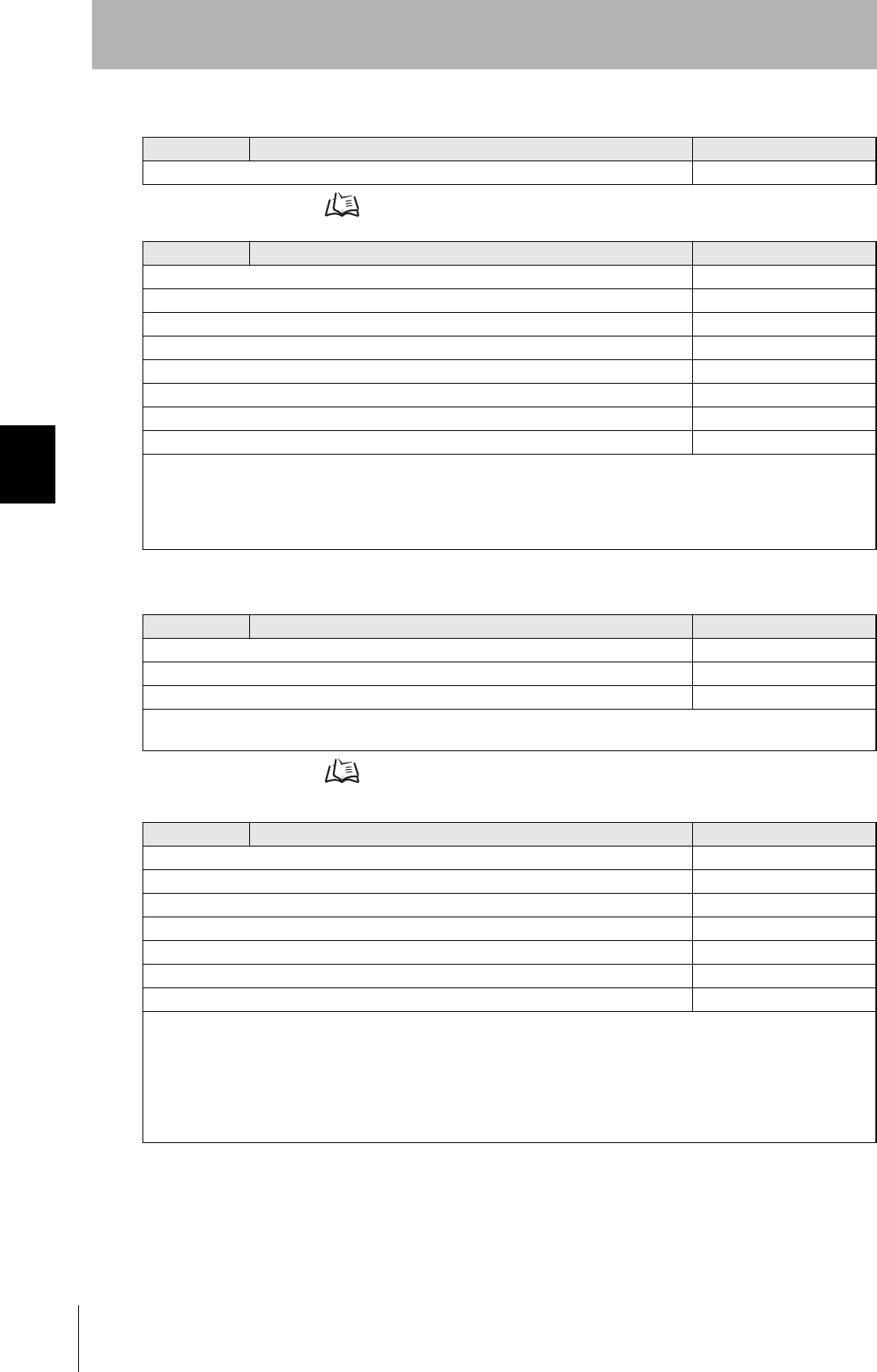
Data Item Dictionary
SECS II data items Name Format Value
ATTRID Attribute ID 20 Attribute name
ATTRVAL Attribute value 20 Attribute value
MID Carrier ID MID 2016 to 7E16 (Visible ASCII)
DATA Data 20 All characters 00H-0FFH
DATALENGTH DataSize 52 Offset designation: 1 to 224
Segment designation:
Refer to ID Tag Memory Maps page 147.
DATASEG DataSeg 20 Offset designation: "00", "01"..."0222", "0223"
Segment designation:
Refer to ID Tag Memory Maps page 147.
STATUS PM information 20 "NE": Normally executed
71
CIDRW System
User’s Manual
SECTION 4
When SECS Is Used
SECTION 4
Reading from/Writing to ID Tags
*1: “PS” is an expansion command for this Unit.
*2: When the TARGET ID is "00" (CIDRW), this is a zero length item.
*3: "EE," "HE," and "TE" are used only with S18F6, S18F8, S18F10, and S18F12.
S9F7 Responses
An S9F7 response is given when a message in an illegal format is received from the host device.
"Illegal format" here means that there is a problem with the message composition, such as illegal attributes, or insuffi-
cient or too many items. If other problems relating to the item contents arise, the response is SSACK = "CE" (communi-
cations error).
Communications with the Host Device
Communicate with the host device only after confirming that the CIDRW Controller has started. Also, unstable signals
may occur at the host interface when the CIDRW Controller is started. When initializing operation, clear the reception
buffer at the host device or take other suitable methods to clear unwanted signals.
SSACK Result status 20 "NO": Normal
"EE": Execution error *3
"CE": Communications error
"HE": Hardware error *3
"TE": Tag error *3
List of STATUS Status L,4
1.<PMInformation>
2.<AlarmStatus>
3.<OperationalStatus>
4.<HeadStatus> *2
The STATUS values are included in the PM infor-
mation.
CPVAL State request 20 "OP", "MT", "PS" *1
TARGETID Target ID 20 "00"-"31"
"00" indicates the CIDRW Controller itself.
SSCMD Subsystem com-
mands
20 "ChangeState"
"GetStatus"
"PerformDiagnostics"
"Reset"
Data Item Dictionary
SECS II data items Name Format Value
72
SECTION 4
When SECS Is Used
CIDRW System
User’s Manual
SECTION 4
Reading from/Writing to ID Tags
■Specifications for Each Stream/Function
• Online Check
• Get Attributes
S1,F1 Are You There Request S,H→E,reply
Header only
S1,F2 On Line Data S,H←E
L,2
1.<MDLN>
2.<SOFTREV>
• Set MDLN (model number).
• Set SOFTREV (software revision level).
S18,F1 Read Attribute Request S,H→E,reply
L,2
1.<TARGETID> "00"-"31"
2.L,n
1.<ATTRID1>
⋅
n.<ATTRIDn>
• The setting for reading all attributes (CIDRW Controller or Heads) is n = 0.
S18,F2 Read Attribute Data S,H←E
L,4
1.<TARGETID> "00"-"31"
2.<SSACK>
3.L,n
1.<ATTRVAL1>
⋅
n.<ATTRVALn>
4.L,s
1.<STATUS1>
⋅
s.<STATUSs>
• The order of the attribute data corresponds to the attribute ID specified by S18, F1.
When reading of all attributes is specified, unsupported attribute items (ATTRVAL) are omitted.
• When the specified target is invalid:
n = 0, s = 0, SSACK = "CE" communications error
• When one or more undefined attributes are included:
n = 0, s = 0, SSACK = "CE" communications error
• When Head attributes are specified with TARGET = “00” or CIDRW Controller attributes are specified with TARGET <> “00”:
n = 0, s = 0, SSACK = “CE” communications error
• If the status of SSACK is other than "NO" (normal), the List of Status will comprise zero items.

73
CIDRW System
User’s Manual
SECTION 4
When SECS Is Used
SECTION 4
Reading from/Writing to ID Tags
• Set Attributes
F18,F3 Write Attribute Request S,H→E,reply
L,2
1.<TARGETID> "00" (fixed)
2.L,n
1.L,2
1.<ATTRID1>
2.<ATTRVAL1>
n.L,2
1.<ATTRIDn>
2,<ATTRVALn>
Since the attributes for Heads are all RO in this system, the target ID is fixed as “00”.
S18,F4 Write Attribute Acknowledge S,H←E
L,3
1.<TARGETID> "00" (fixed)
2.<SSACK>
3.L,s
1.<STATUS1>
⋅
s.<STATUSs>
• When the specified target is invalid:
s = 0, SSACK = "CE" communications error
• When one or more undefined attributes or RO attributes are included:
s = 0, SSACK = "CE" communications error
• When illegal attribute data is specified:
s = 0, SSACK = "CE" communications error
• If the status of SSACK is other than "NO" (normal), the List of Status will comprise zero items.
74
SECTION 4
When SECS Is Used
CIDRW System
User’s Manual
SECTION 4
Reading from/Writing to ID Tags
• Read Data
ID Tag Memory Maps Refer to page 147.
S18,F5 Read Request S,H→E,reply
L,3
1.<TARGETID> "01"-"31"
2.<DATASEG>
3.<DATALENGTH>
• When DATASEG is specified as "0" and a character string, the size of data determined by the DATALENGTH setting is read,
starting from the address indicated by the DATASEG setting. If DATALENGTH = 0, data is read up to the end of the data
area.
• If DATASEG is specified as a character string, a size of data determined by DATALENGTH, starting from the address speci-
fied by DATASEG, is read (segment specification).
• When the data of all segments is batch read, both DATASEG and DATALENGTH are omitted (they are zero length items).
• When all the data for a particular segment is read, DATALENGTH is omitted (it is a zero length item).
• In a segment specification, it is not possible to specify a DATALENGTH that exceeds the maximum length of the relevant
DATASEG.
• In a segment specification, if a DATALENGTH that is under the set length for DATASEG is specified, only the data corre-
sponding to specified DATALENGTH is read.
S18,F6 Read Data S,H→E,reply
L,4
1.<TARGETID> "01"-"31"
2.<SSACK>
3.<DATA>
4.L,s
1.<STATUS1>
⋅
s.<STATUSs>
• When the specified target is invalid:
DATA item length = 0, s = 0, SSACK = "CE" communications error
• In an address specification, if:
(SEGMENT + DATALENGTH) ≤ total value for all segments then SSACK = "NO"
• In an address specification, if:
(SEGMENT + DATALENGTH) > total value for all segments then DATA item length = 0, s = 0, SSACK = "CE" communica-
tions error
• In a segment specification, if an undefined DATASEG is specified, or if the DATALENGTH is illegal:
DATA item length = 0, s = 0, SSACK = "CE" communications error
• When reading of all segment data is specified in a system where the data segment is not defined:
DATA length = 0, SSACK = "NO"
• If the status of SSACK is other than "NO" (normal), the List of Status will comprise zero items.
75
CIDRW System
User’s Manual
SECTION 4
When SECS Is Used
SECTION 4
Reading from/Writing to ID Tags
• Write Data
ID Tag Memory Maps Refer to page 147.
S18,F7 Write Request S,H→E,reply
L,4
1.<TARGETID> "01"-"31"
2.<DATASEG>
3.<DATALENGTH>
4.<DATA>
• If DATASEG is specified as "0" and a character string, a size of data corresponding to the DATALENGTH setting and starting
from the address within the data area indicated by the DATASEG setting is written (address specification). If DATALENGTH
= 0, data is written up to the end of the data area.
• If DATASEG is specified as a character string, a size of data determined by DATALENGTH, starting from the address speci-
fied by DATASEG, is written (segment specification).
• When the data for all segments is batch written, both DATASEG and DATALENGTH are omitted (they are zero length items).
• When all the data for a particular segment is written, DATALENGTH is omitted (it is a zero length item).
• In a segment specification, it is not possible to specify a DATALENGTH that exceeds the maximum length of the relevant
DATASEG.
• In a segment specification, if a DATALENGTH that is under the set length for DATASEG is specified, only the data corre-
sponding to the specified DATALENGTH is written, compressed into the smaller addresses.
• The item lengths of DATASEG and DATA must be matched.
• If DATASEG and DATALENGTH are both omitted (made zero length items), the length of DATA must match the total of the
set lengths of all segments.
S18,F8 Write Acknowledge S,H←E
L,3
1.<TARGETID> "01"-"31"
2.<SSACK>
3.L,s
1.<STATUS1>
⋅
s.<STATUSs>
• When the specified target is invalid:
s = 0, SSACK = "CE" communications error
• In an address specification, if:
(SEGMENT + DATALENGTH) ≤ total value for all segments then SSACK = "NO"
• In an address specification, if:
(SEGMENT + DATALENGTH) > total value for all segments then DATA item length = 0, s = 0, SSACK = "CE" (communica-
tions error)
• In a segment specification, if DATASEG and DATALENGTH are illegal:
s = 0, SSACK = "CE" communications error
• If the status of SSACK is other than "NO" (normal), the List of Status will comprise zero items.
76
SECTION 4
When SECS Is Used
CIDRW System
User’s Manual
SECTION 4
Reading from/Writing to ID Tags
• Read ID
ID Tag Memory Maps Refer to page 147.
• Write ID
ID Tag Memory Maps Refer to page 147.
S18,F9 Read ID Request S,H→E,reply
1.<TARGETID> "01"-"31"
S18,F10 Read ID Data S,H←E
L,4
1.<TARGETID> "01"-"31"
2.<SSACK>
3.<MID>
4.L,s
1.<STATUS1>
⋅
s.<STATUSs>
• If the MID data contains Non-Visible ASCII code:
s = 0, MID item length = 0, SSACK = "EE" execution error
• When the specified target is invalid:
s = 0, MID item length = 0, SSACK = "CE" communications error
• If the status of SSACK is other than "NO" (normal), the List of Status will comprise zero items.
S18,F11 Write ID Request S,H→E,reply
L,2
1.<TARGETID> "01"-"31"
2.<MID>
• If an MID that is under the length set for the CarrierIDlength attribute is specified, an error occurs and the MID data is not
written.
S18,F12 Write ID Acknowledge S,H←E
L,3
1.<TARGETID> "01"-"31"
2.<SSACK>
3.L,s
1.<STATUS1>
⋅
s.<STATUSs>
• When the specified target is invalid:
s = 0, SSACK = "CE" communications error
• When there is an MID length error:
s = 0, SSACK = "CE" communications error
• If the MID data contains Non-Visible ASCII code:
s = 0, SSACK = "EE" execution error
• If the status of SSACK is other than "NO" (normal), the List of Status will comprise zero items.
77
CIDRW System
User’s Manual
SECTION 4
When SECS Is Used
SECTION 4
Reading from/Writing to ID Tags
• Subsystem Command (ChangeState)
S18,F13 Subsystem Command Request (ChangeState) S,H→E,reply
L,3
1.<TARGETID> "00" (fixed)
2.<SSCMD> "ChangeState"
3.L,1
1.<CPVAL1> "OP", "MT" or "PS"
CPVAL = "PS" is a parameter setting unique to this CIDRW Controller for switching to the Setting mode.
S18,F14 Subsystem Command Acknowledge (ChangeState) S,H←E
L,3
1.<TARGETID> "00"
2.<SSACK>
3.L,s
1.<STATUS1>
⋅
s.<STATUSs>
• When the specified target is invalid:
s = 0, SSACK = "CE" communications error
• When SSCMD is invalid:
s = 0, SSACK = "CE" communications error
• When OperationalStatus is BUSY:
s = 0, SSACK = “EE” execution error
• If the status of SSACK is other than "NO" (normal), the List of Status will comprise zero items.
78
SECTION 4
When SECS Is Used
CIDRW System
User’s Manual
SECTION 4
Reading from/Writing to ID Tags
• Subsystem Command (GetStatus)
• Subsystem Command (PerformDiagnostics)
S18,F13 Subsystem Command Request (GetStatus) S,H→Ε,reply
L,3
1.<TARGETID> "00"-"31"
2.<SSCMD> "GetStatus"
3.L,0
S18,F14 Subsystem Command Acknowledge (GetStatus) S,H←E
L,3
1.<TARGETID> "00"-"31"
2.<SSACK> "GetStatus"
3.L,s
1.<STATUS1>
⋅
s.<STATUSs>
• When the specified target is invalid:
s = 0, SSACK = “CE” communications error
• When SSCMD is invalid:
s = 0, SSACK = “CE” communications error
• If the status of SSACK is other than "NO" (normal), the List of Status will comprise zero items.
S18,F13 Subsystem Command Request (PerformDiagnostics) S,H→E,reply
L,3
1.<TARGETID> "00"-"31"
2.<SSCMD> "PerformDiagnostics"
3.L,0
S18,F14 Subsystem command Acknowledge (PerformDiagnostics) S,H←E
L,3
1.<TARGETID> "00"-"31"
2.<SSACK>
3.L,s
1.<STATUS1>
⋅
s.<STATUSs>
• When the specified target is invalid:
s = 0, SSACK = “CE” communications error
• When SSCMD is invalid:
s = 0, SSACK = “CE” communications error
• If the status of SSACK is other than "NO" (normal), the List of Status will comprise zero items.

79
CIDRW System
User’s Manual
SECTION 4
When SECS Is Used
SECTION 4
Reading from/Writing to ID Tags
• Subsystem Command (Reset)
S18,F13 Subsystem Command Request (Reset) S,H→E,reply
L,3
1.<TARGETID> "00" (fixed)
2.<SSCMD> "Reset"
3.L,0
S18,F14 Subsystem Command Acknowledge (Reset) S,H←E
L,3
1.<TARGETID> "00"
2.<SSACK>
3.L,0
• When the specified target is invalid:
SSACK = “CE” communications error
• When SSCMD is invalid:
SSACK = “CE” communications error

80
SECTION 4
When SECS Is Used
CIDRW System
User’s Manual
SECTION 4
Reading from/Writing to ID Tags
■Operation Conditions
The response messages and response codes (SSACK) in each state are shown below.
State Initializing Operating Maintenance
Message Function IDLE BUSY
S1,F1 OnlineRequest S1,F0 S1,F2 S1,F2 S1,F2
S18,F11 WriteID S18,F0 S18,F0 S18,F0 NO
S18,F7 WriteData S18,F0 NO NO S18,F0
S18,F3 SetAttribute S18,F0 NO NO NO
S18,F13(Reset) Reset S18,F0 NO NO NO
S18,F9 ReadID S18,F0 NO NO NO
S18,F5 ReadData S18,F0 NO NO S18,F0
S18,F13(PerformDiagnostics) Diagnostics S18,F0 NO NO NO
S18,F13(GetStatus) GetStatus S18,F0 NO NO NO
S18,F1 GetAttribute S18,F0 NO NO NO
S18,F13(ChangeState) ChangeState(to MT) S18,F0 NO S18,F0 S18,F0
S18,F13(ChangeState) ChangeState(to OP) S18,F0 S18,F0 S18,F0 NO
S18,F13(ChangeState) ChangeState(to PS) S18,F0 NO S18,F0 NO
81
CIDRW System
User’s Manual
SECTION 4
When SECS Is Not Used
SECTION 4
Reading from/Writing to ID Tags
When SECS Is Not Used
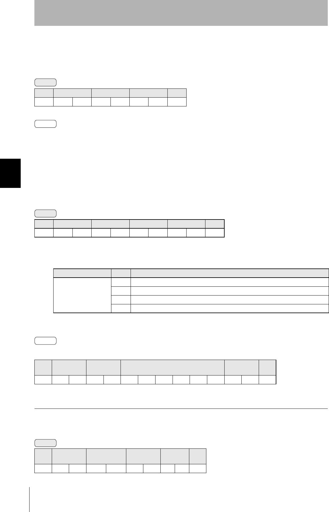
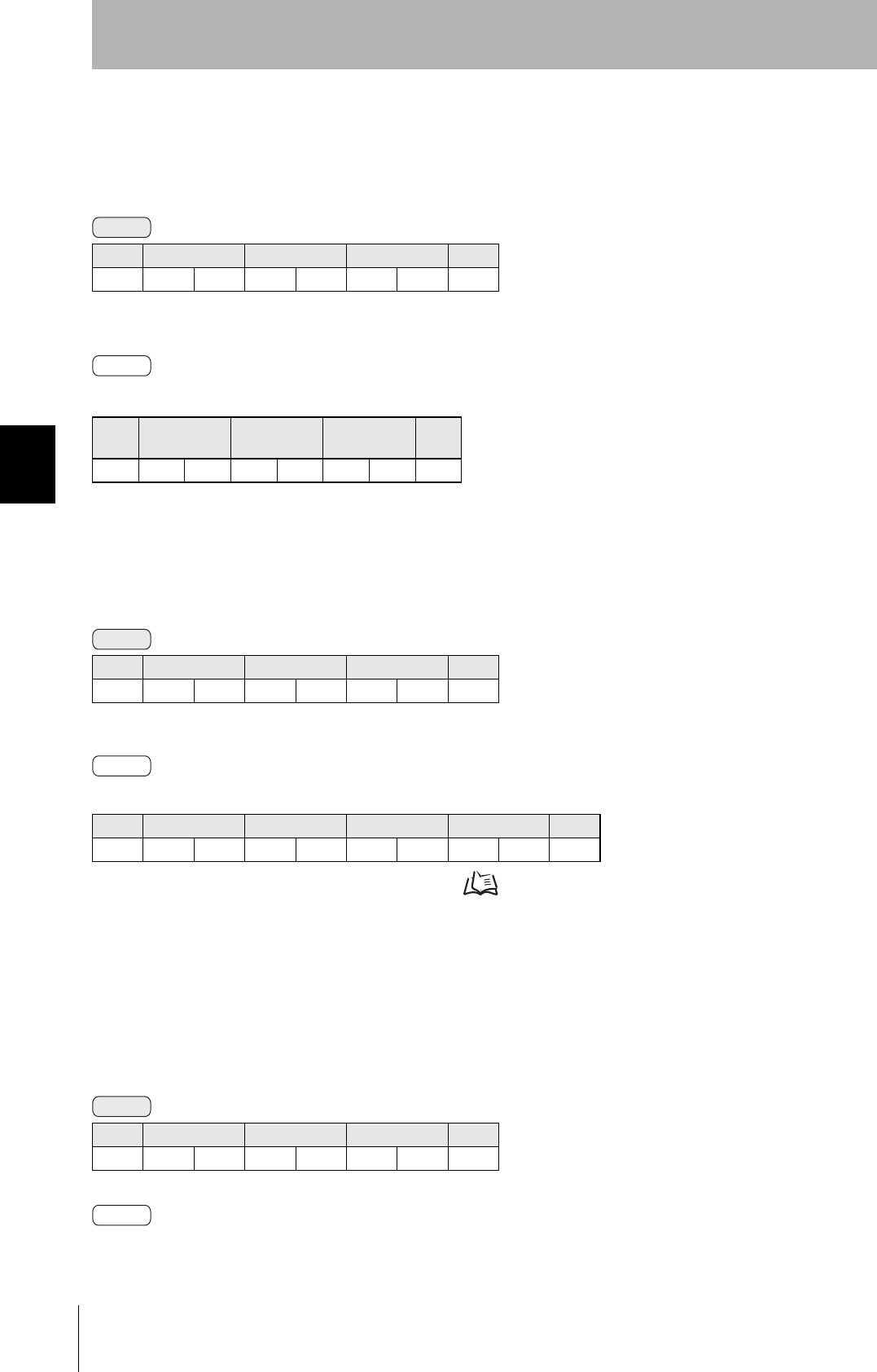
Command/Response Format
■1:N Protocol
■1:1 Protocol
Meaning of FCS (frame check sequence)
This is two ASCII code characters obtained by conversion from the 8-bit exclusive logical sum (EOR) of the characters
from the character immediately after SOH to the character immediately before FCS.
Command
SOH Node No. Command code Parameter FCS CR
1 ⋅ ⋅ ⋅ n
01h 0Dh
Response
SOH Node No. Response
code
Parameter FCS CR
1 ⋅ ⋅ ⋅ n
01h 0Dh
Command
Command code Parameter CR
1 ⋅ ⋅ ⋅ n
0Dh
Response
Response
code
Parameter CR
1 ⋅ ⋅ ⋅ n
0Dh

82
SECTION 4
When SECS Is Not Used
CIDRW System
User’s Manual
SECTION 4
Reading from/Writing to ID Tags
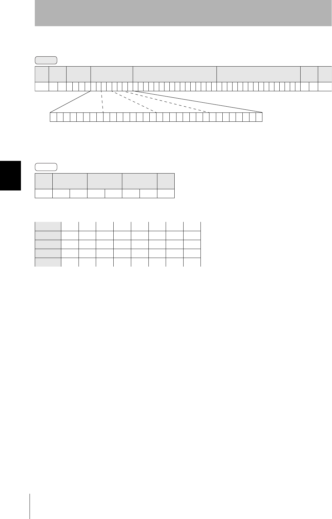
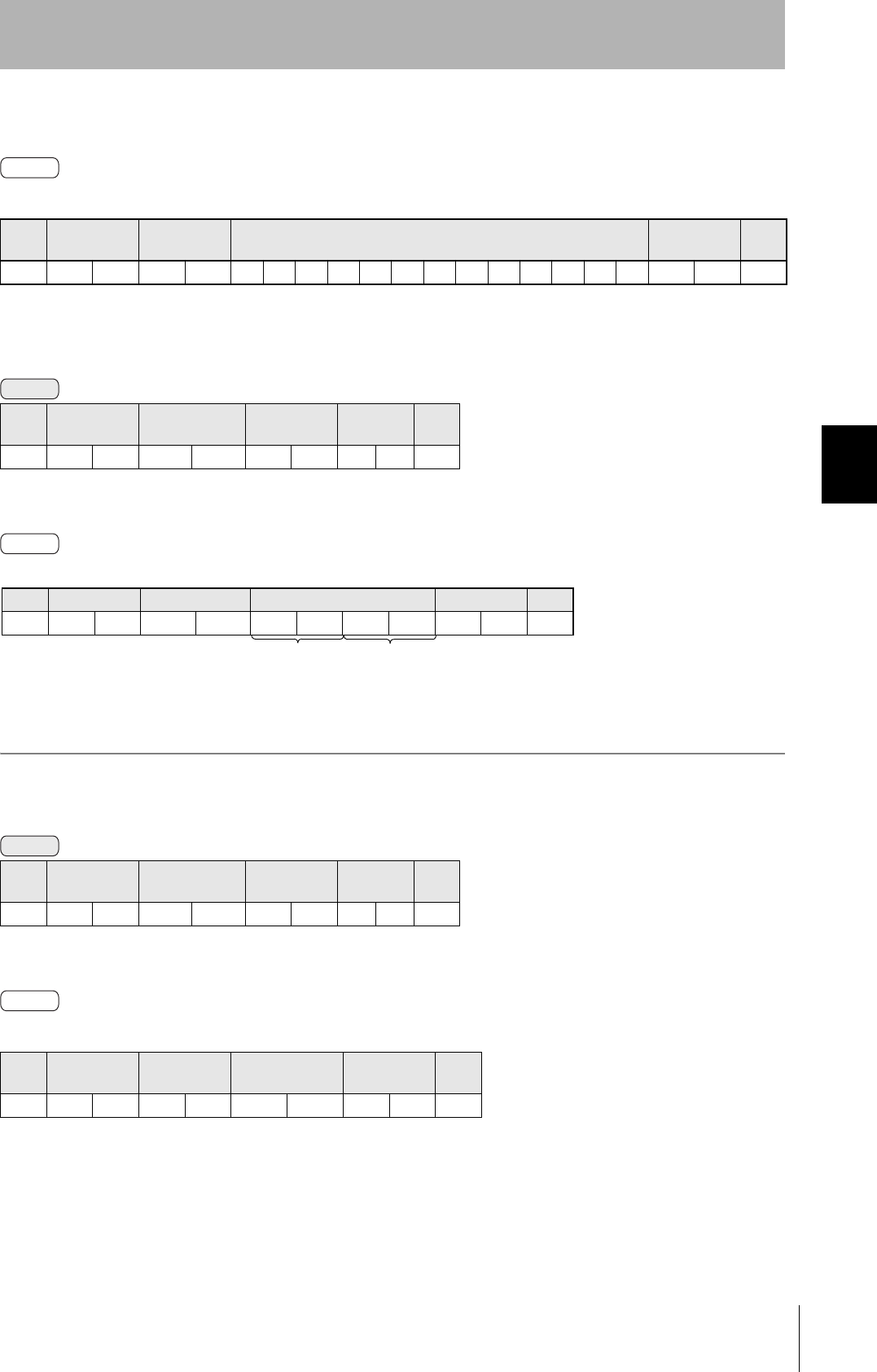
Example: Reading the data of page 1 and page 2 of node No.1
Command
Calculation range
(ASCII conversion)
83
CIDRW System
User’s Manual
SECTION 4
When SECS Is Not Used
SECTION 4
Reading from/Writing to ID Tags
Command
Communications with the Host Device
Communicate with the host device only after confirming that the CIDRW Controller has started. Also, unstable signals
may occur at the host interface when the CIDRW Controller is started. When initializing operation, clear the reception
buffer at the host device or take other suitable methods to clear unwanted signals.
The command and response details are given for a 1:N protocol. Just as in the previous command format, the
details for a 1:1 protocol are the same if the SOH, node number, and FCS are deleted.
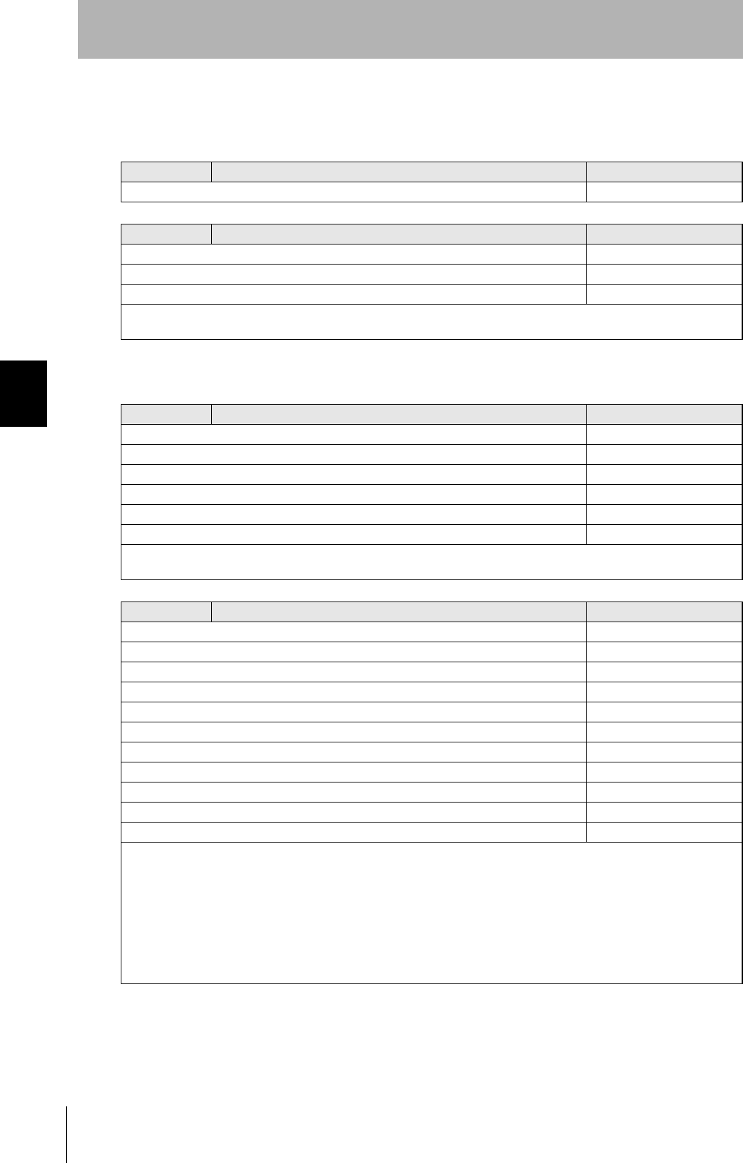
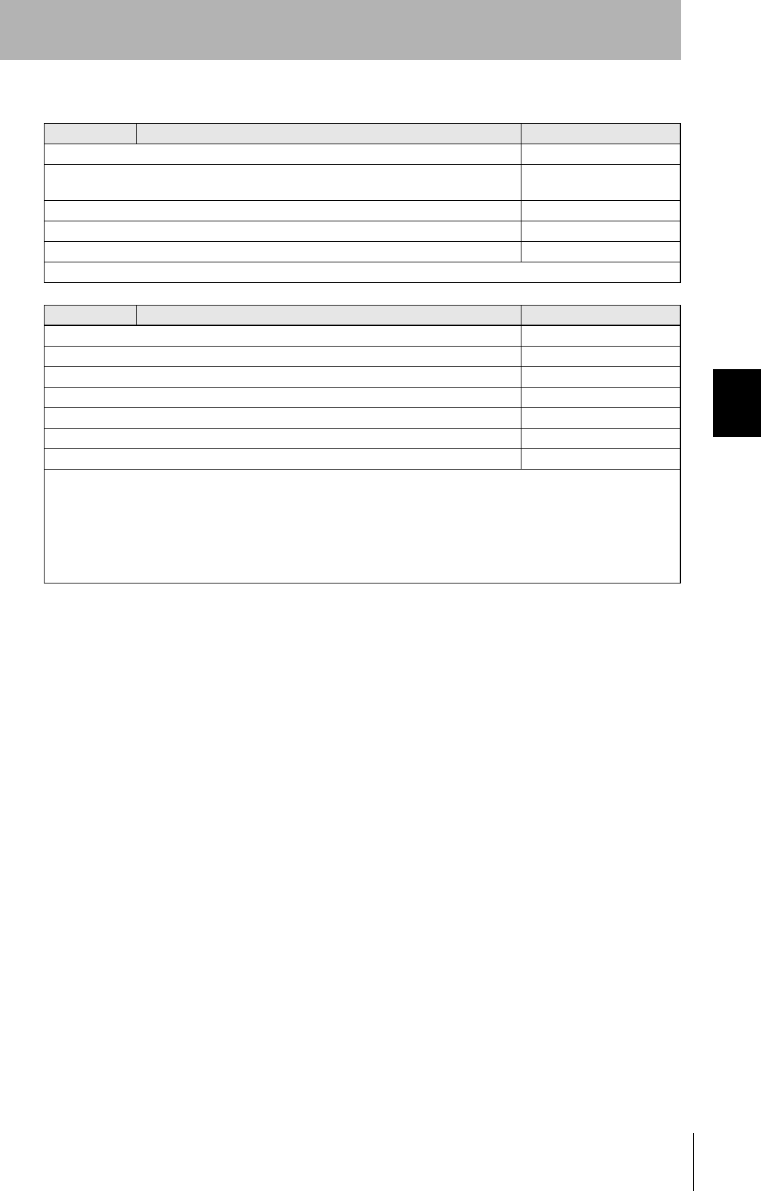
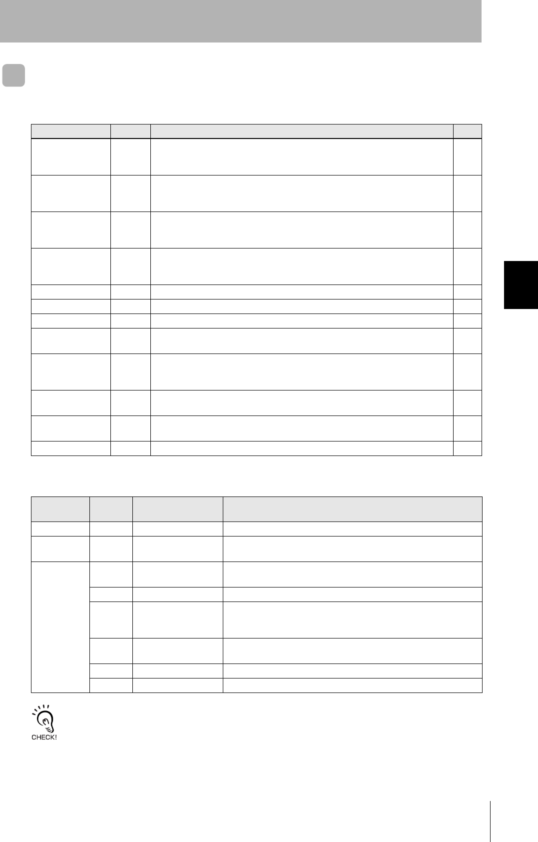
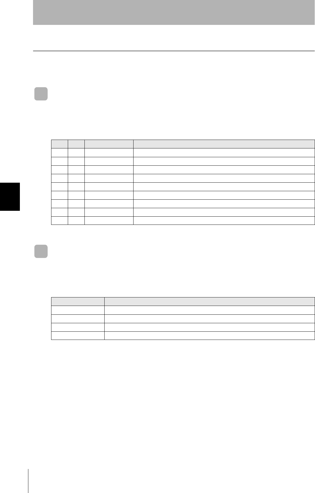
Command Code List
Name Value Function See
READ 0100 When this command is received, the system communicates with the ID Tag, and
reads the specified page(s) of data. Any pages up to a maximum of 16 can be
selected.
p.84
WRITE 0200 When this command is received, the system communicates with the ID Tag, and
writes the specified page(s) of data. Any pages up to a maximum of 16 can be
selected.
p.85
SAME WRITE 0300 When this command is received, the system communicates with the ID Tag, and
writes the same data in page units to the specified pages. Up to 17 pages, which is
the maximum number of pages for an ID Tag, can be specified.
p.87
BYTE WRITE 0400 When this command is received the system communicates with the ID Tag, and
writes data to the area specified by a first address and number of bytes. A maximum
of 128 bytes can be specified.
p.88
TEST 10 Sends received data to the host device. p.89
NAK 12 Sends the response made immediately before again. p.90
GET PARAMETER 14 Gets the model number, MAC address, or another parameter. p.90
GET LAST COM-
MAND
15 Gets the command code of the last command that was executed. p.92
GET COMMUNICA-
TIONS HISTORY
16 Gets the history of communications from when the power was turned ON (total num-
ber of communications, total successful communications, and total number of failed
communications).
p.93
CLEAR COMMUNI-
CATIONS HISTORY
17 Clears the communications history. p.94
NOISE MEASURE-
MENT
40 Measures the noise in the vicinity of the CIDRW Head. p.94
RESET 7F Resets the Amplifier Unit. p.94
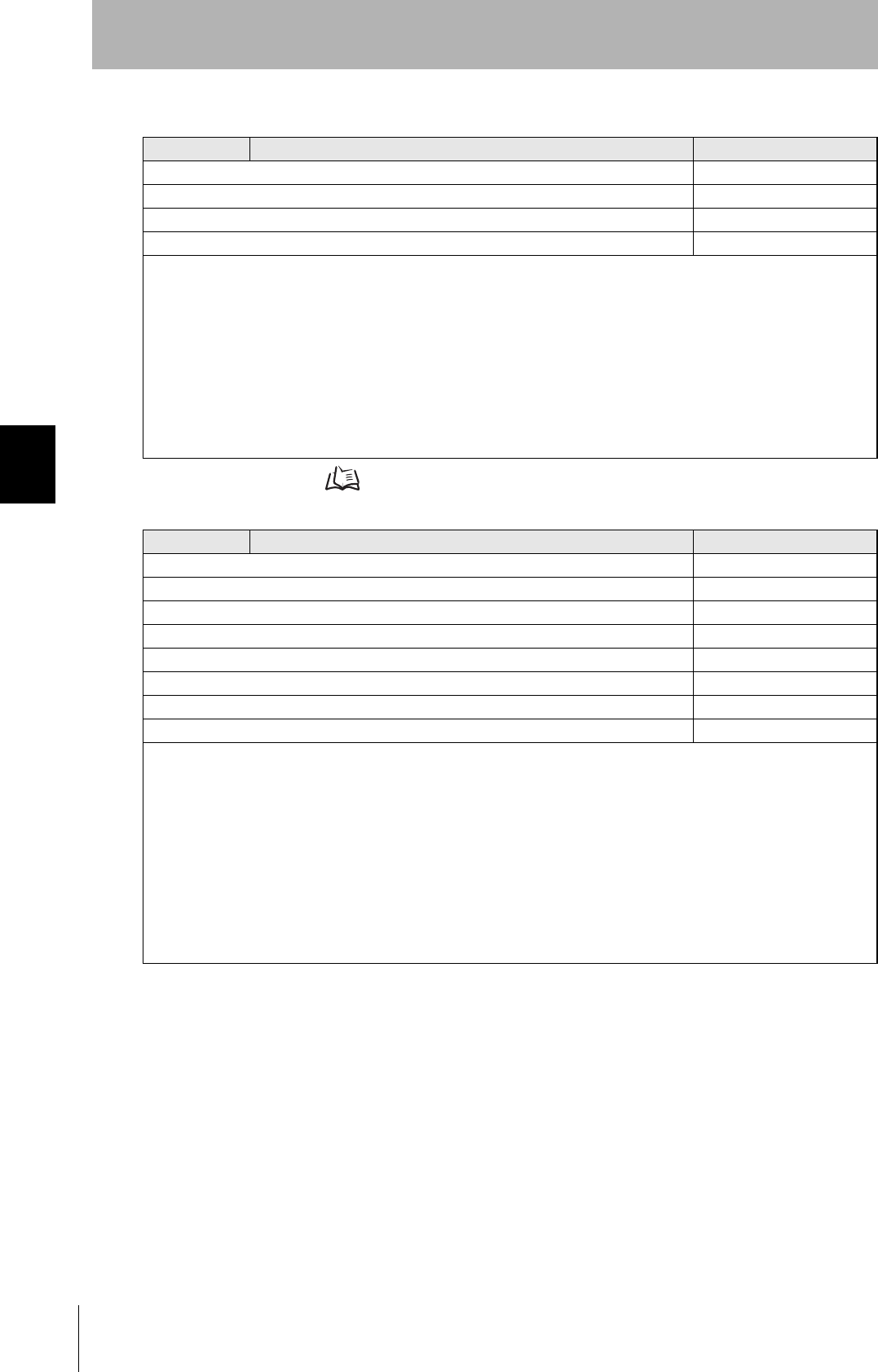
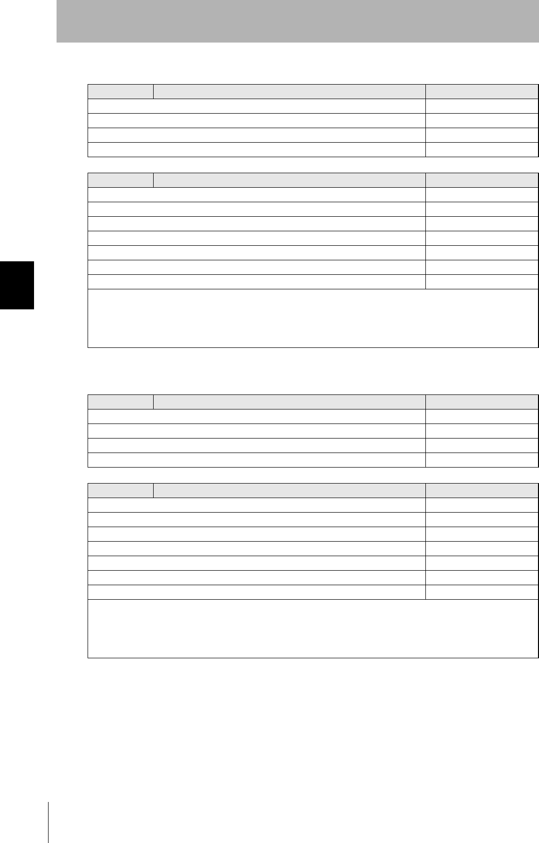
Response Code List
Type Response
code Name Description
Normal end 00 Normal end Command execution is completed normally.
Host commu-
nications error
14 Format error There is a mistake in the command format. (For example, the command
code is undefined, or the page or address specification is inappropriate.)
Communica-
tions error
70 Communications error Noise or another hindrance occurs during communications with an ID
Tag, and communications cannot be completed normally.
71 Verification error Correct data cannot be written to an ID Tag.
72 No Tag error Either there is no ID Tag in front of the CIDRW Head, or the CIDRW
Head is unable to detect the ID Tag due to environmental factors (e.g.,
noise).
7B Outside write area error A write operation was not completed normally because the ID Tag was
in an area in which the ID Tag could be read but not written.
7E ID system error (1) The ID Tag is in a status where it cannot execute command processing.
7F ID system error (2) An inapplicable ID Tag has been used.
84
SECTION 4
When SECS Is Not Used
CIDRW System
User’s Manual
SECTION 4
Reading from/Writing to ID Tags
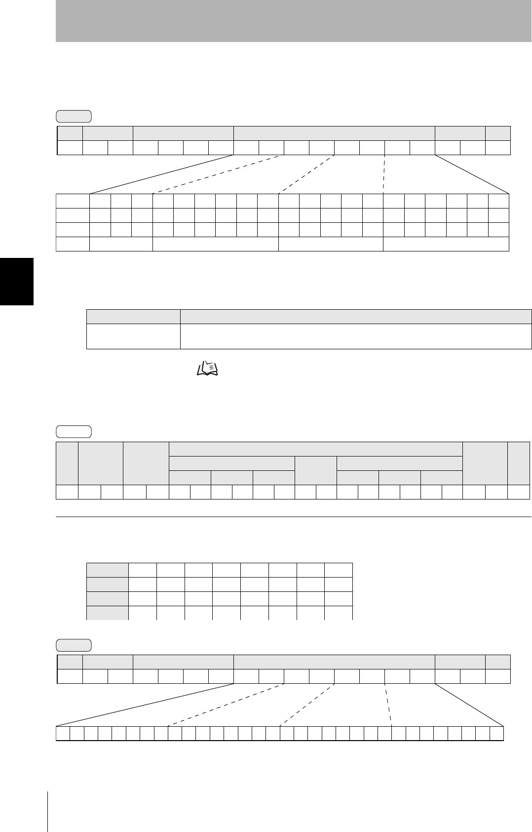
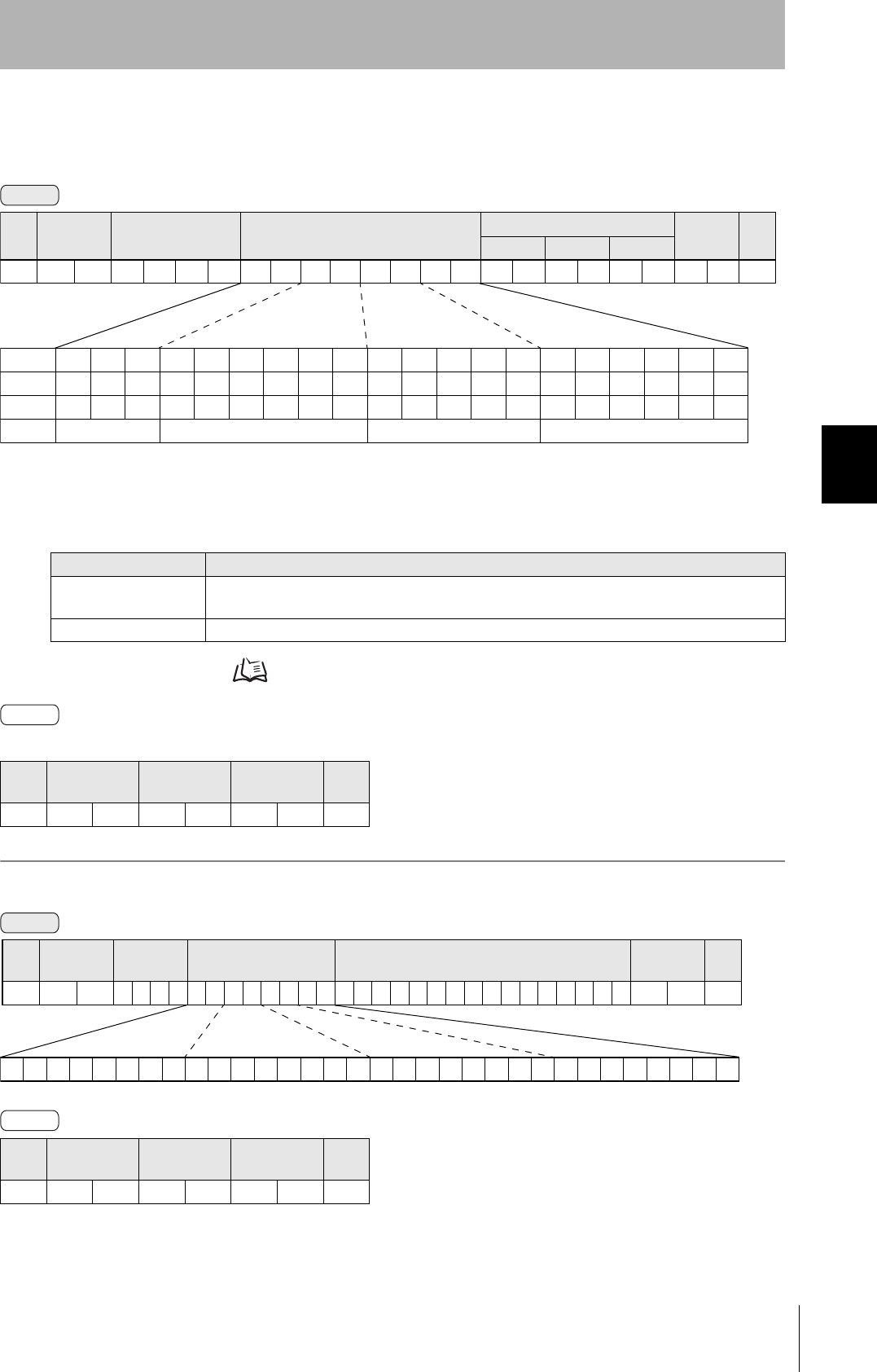
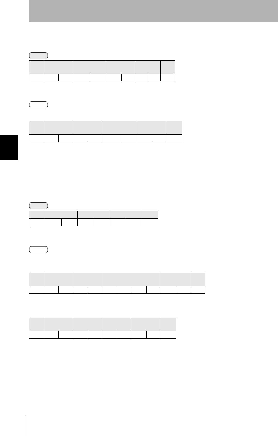
■READ
Reads any pages of data from the ID Tag. The maximum number of pages that can be read at one time
is 16.
ID Tag Memory Maps Refer to page 147.
The response code (when normal: 00) and the data in the specified pages are returned in ascending order of
page numbers.
Example: Reading the data of pages 1 and 3 of node No.1
Parameter Description
Parameter Description
Page designation Pages are specified by setting the bits corresponding to pages that are to be read to 1 and setting
the other bits to 0, then converting the result to a hexadecimal character string.
SOH Node No. Response
code
Read data
FCS CRPage n
⋅ ⋅ ⋅
Page m (n<m)
Data 1 ⋅ ⋅ ⋅ Data 8 Data 1 ⋅ ⋅ ⋅ Data 8
01h 0 0 0Dh
Data Content of the ID Tag
Page 1 12h 34h 56h 78h 90h 12h 34h 56h
Page 2
Page 3 11h 22h 33h 44h 55h 66h 77h 88h
Page 4
Command
Bit 7-07-321076-1076 - 210
Page Sys - Sys Sys - Sys 17 16 15 14 13 - 8 7 6 5 - 1 Sys Sys
Designation 0* 0* 0* 0* 0* 0/1 0/1 0/1 0/1 0/1 ••• 0/1 0/1 0/1 0/1 ••• 0/1 0* 0*
Value 00 00 to 07 00 to FF 00 to FC
* Always specify 0. If you specify 1 an error (Response code: 14) will occur.
SOH Node No. Command code Page designation (8 characters) FCS CR
01h 0100 0Dh
Response
Command
00000000000000000000000000010100
Binary notation
SOH Node No. Command code Page designation FCS CR
01h01010000000014050Dh
85
CIDRW System
User’s Manual
SECTION 4
When SECS Is Not Used
SECTION 4
Reading from/Writing to ID Tags
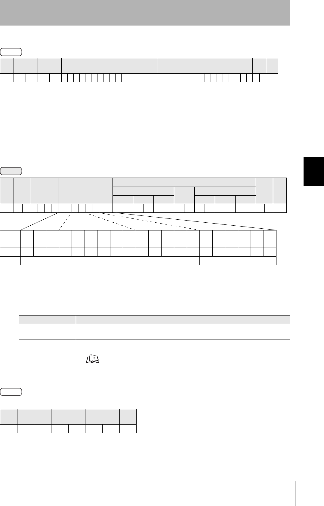
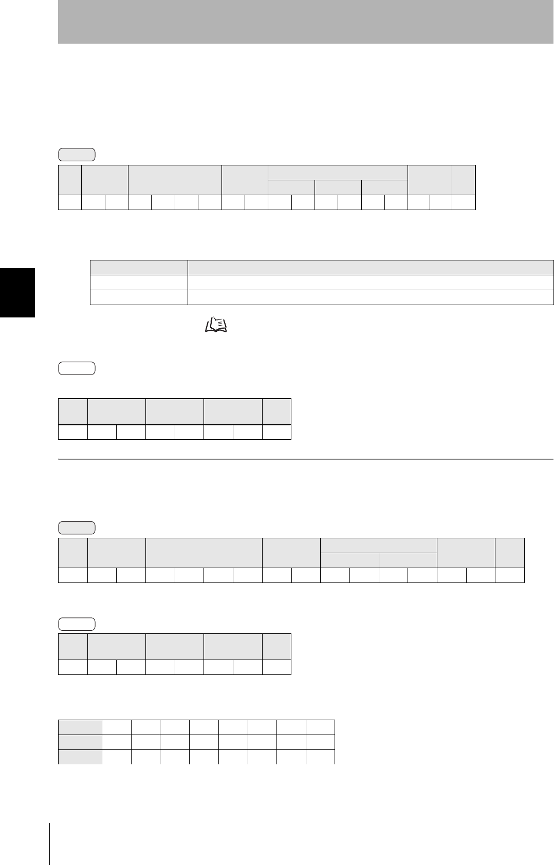
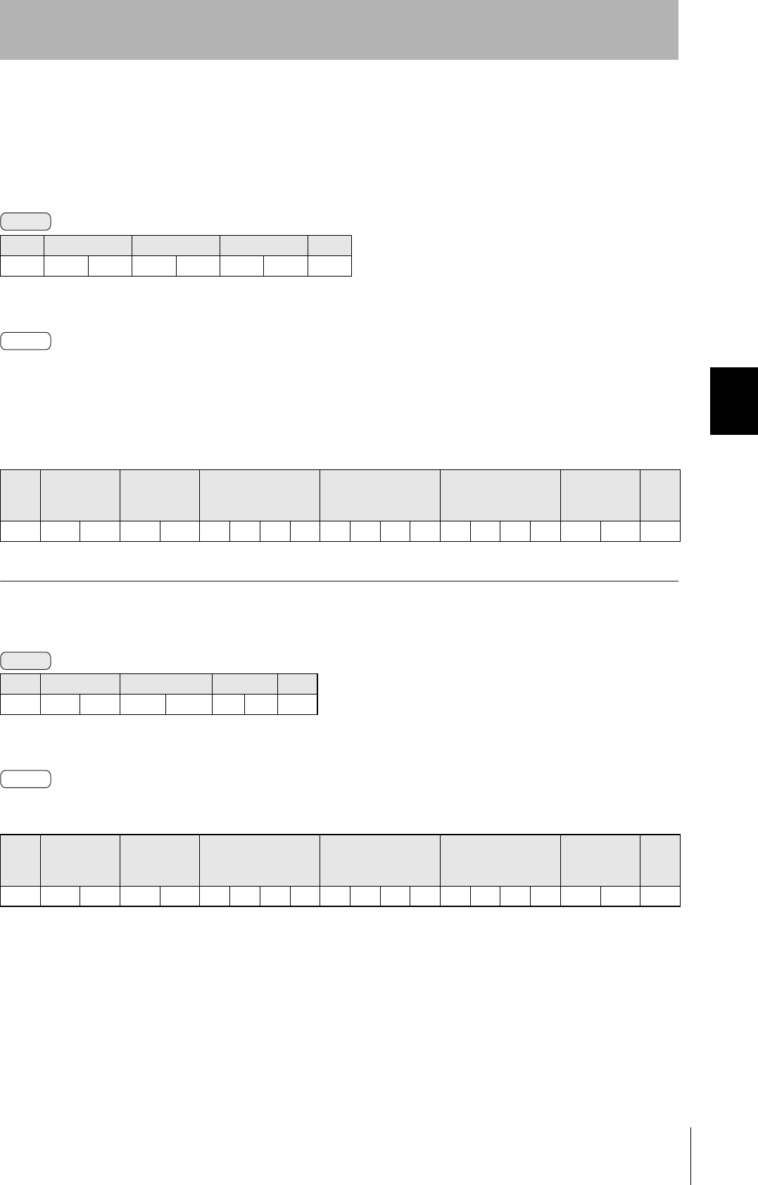
■WRITE
Data is written in page units to the ID Tag. Any page(s) can be specified. It is possible to write to a max-
imum of 16 pages at one time.
ID Tag Memory Maps Refer to page 147.
The response code (when normal: 00) is returned.
SOH Node No. Response
code Page 1 Page 3 FCS CR
01h010012345678901234561122334455667788070Dh
Parameter Description
Parameter Description
Page designation Pages are specified by setting the bits corresponding to pages that are to be read to 1 and setting
the other bits to 0, then converting the result to a hexadecimal character string.
Write data The data to be written to the specified pages is specified in ascending order of page numbers.
SOH Node No. Response
code FCS CR
01h 0 0 0Dh
Response
Command
Bit 7-07-321076-1076 - 210
Page Sys - Sys Sys - Sys 17 16 15 14 13 - 8 7 6 5 - 1 Sys Sys
Designation 0* 0* 0* 0* 0* 0/1 0/1 0/1 0/1 0/1 ••• 0/1 0/1 0/1 0/1 ••• 0/1 0* 0*
Value 00 00 to 07 00 to FF 00 to FC
* Always specify 0. If you specify 1 an error (Response code: 14) will occur.
SOH Node
No.
Command
code
Page designation
(8 characters)
Write data
FCS CRPage n
⋅ ⋅ ⋅
Page m (n<m)
Data 1 ⋅ ⋅ ⋅ Data 8 Data 1 ⋅ ⋅ ⋅ Data 8
01h 0200 0DH
Response
86
SECTION 4
When SECS Is Not Used
CIDRW System
User’s Manual
SECTION 4
Reading from/Writing to ID Tags
Example: Writing data to pages 8 and 10 of node No.1
The ID Tag status on normal completion is as shown below.
SOH Node No. Response
code FCS CR
01h0100010Dh
Page 8 11h 22h 33h 44h 55h 66h 77h 88h
Page 9
Page 10 01h 23h 45h 67h 89h ABh CDh EFh
Command
00000000000000000000101000000000
SOH Node
No.
Command
code
Page designation Data of page 8 Data of page 10 FCS CR
01h 0 1 0 2 0 000000A0011223344556677880123456789ABCDEF 7 4 0Dh
Binary notation
Response
87
CIDRW System
User’s Manual
SECTION 4
When SECS Is Not Used
SECTION 4
Reading from/Writing to ID Tags
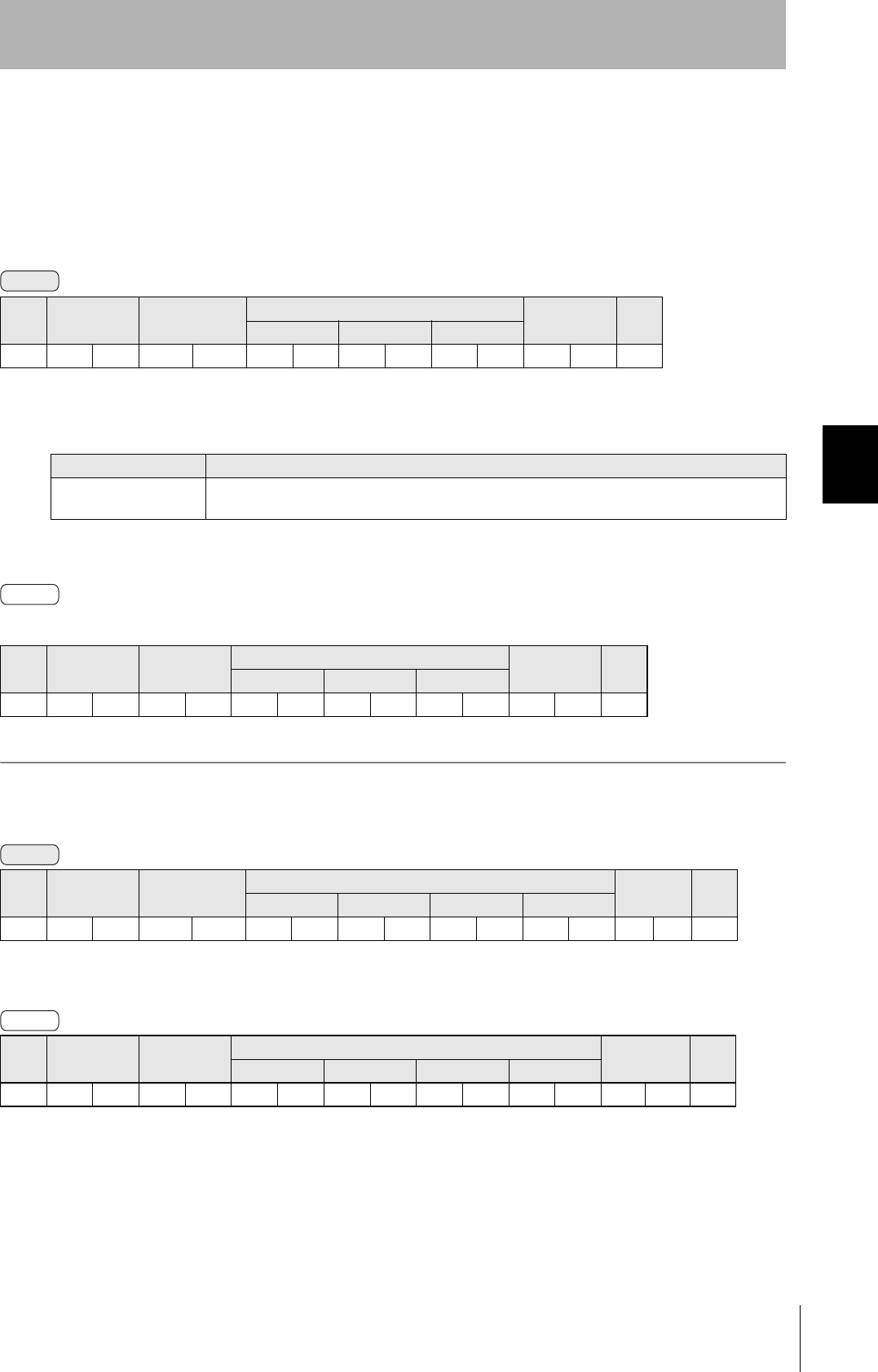
■SAME WRITE
This command writes the same data to multiple pages of an ID Tag. Any page(s) can be specified.
ID Tag Memory Maps Refer to page 147.
The response code (when normal: 00) is returned.
Example: Clearing pages 1 to 17 of node No.1 to 0
Parameter Description
Parameter Description
Page designation Pages are specified by setting the bits corresponding to pages that are to be read to 1 and setting
the other bits to 0, then converting the result to a hexadecimal character string.
Write data Specify the write data.
SOH Node No. Response
code FCS CR
01h 0 0 0Dh
SOH Node No. Response
code FCS CR
01h0100010Dh
Command
SOH Node No. Command code Page designation (8 characters) Write data FCS CR
Data 1 ⋅ ⋅ ⋅ Data 8
01h 0 3 0 0 0DH
Bit 7-07-321076-1076 - 210
Page Sys - Sys Sys - Sys 17 16 15 14 13 - 8 7 6 5 - 1 Sys Sys
Designation 0* 0* 0* 0* 0* 0/1 0/1 0/1 0/1 0/1 ••• 0/1 0/1 0/1 0/1 ••• 0/1 0* 0*
Value 00 00 to 07 00 to FF 00 to FC
* Always specify 0. If you specify 1 an error (Response code: 14) will occur.
Response
Command
00000000000001111111111111111100
Binary notation
SOH Node No. Command
code Page designation Write data FCS CR
01h 0 1 03000007FFFC0000000000000000 0 0 0Dh
Response
88
SECTION 4
When SECS Is Not Used
CIDRW System
User’s Manual
SECTION 4
Reading from/Writing to ID Tags
■BYTE WRITE
This command writes data to any specified number of bytes starting from the address specified in the
ID Tag. The maximum number of bytes that can be written at one time is 128.
* Data number n = number of bytes written to (2-character units)
ID Tag Memory Maps Refer to page 147.
The response code (when normal: 00) is returned.
Example: Writing to two bytes starting from address 05h of node No.1
The ID Tag status on normal completion is as shown below.
SOH Node No. Command code First
address
Write data FCS CR
Data 1 ••• Data n
01h 0400 0Dh
Parameter Description
Parameter Description
First address Addresses can be specified in the range 00h to 87h.
Write data Up to 128 bytes of write data, starting from the specified address, can be specified.
SOH Node No. Response
code FCS CR
01h 0 0 0Dh
SOH Node No. Command code First address Write data FCS CR
Data 1 Data 2
01h010400051234040Dh
SOH Node No. Response
code FCS CR
01h0100010Dh
Page 1 12h 34h
Page 2
Command
Response
Command
Response
89
CIDRW System
User’s Manual
SECTION 4
When SECS Is Not Used
SECTION 4
Reading from/Writing to ID Tags
■TEST
Performs a communications test on communications between the host device and Amplifier Unit.
When an Amplifier Unit receives a test command, it sends the response code and command test data
to the host device as the response.
* Number of data n < 136 (2-character units)
The response code (when normal: 00) and the received test data are returned.
Example: Testing by sending the data 12345678 to node No.1
SOH Node No. Command code Test data FCS CR
Data 1 ••• Data n
01h 1 0 0Dh
Parameter Description
Parameter Description
Test data The data to be sent in the test is specified with a hexadecimal value. (270 characters max.)
However, note that odd numbers of characters cannot be used.
SOH Node No. Response
code
Test data FCS CR
Data 1 ••• Data n
01h 0 0 0Dh
SOH Node No. Command code Test data FCS CR
Data 1 Data 2 Data 3 Data 4
01h01 1 0 12345678080Dh
SOH Node No. Response
code
Test data FCS CR
Data 1 Data 2 Data 3 Data 4
01h010012345678090Dh
Command
Response
Command
Response
90
SECTION 4
When SECS Is Not Used
CIDRW System
User’s Manual
SECTION 4
Reading from/Writing to ID Tags
■NAK
Sends the response made immediately before again.
Sends the response made immediately before again.
■GET PARAMETER
This command gets the model number, firmware version, or another parameter.
The response code (00: normal) and received parameter value are returned.
* The contents and length of the parameter value depend on the parameter type that is specified for the command.
Example 1: Getting the Model Number of Node 1
SOH Node No. Command code FCS CR
01h 1 2 0Dh
SOH Node No. Command code Parameter type FCS CR
01h 1 4 0Dh
Parameter Description
Parameter Value Description
Parameter type 01 Model number
02 Firmware version
20 Memory status
21 Antenna connection status
SOH Node No. Response
code Parameter value FCS CR
01h 0 0 0Dh
SOH Node No. Command code Parameter
type FCS CR
01h 0 1 1 4 0 1 0 5 0Dh
Command
Response
Command
Response
Command
91
CIDRW System
User’s Manual
SECTION 4
When SECS Is Not Used
SECTION 4
Reading from/Writing to ID Tags
The product model number is returned as an ASCII text string.
Example 2: Getting the Firmware Version of Node 1
The response code (00: normal) and firmware version are returned as a 4-digit decimal number.
* The above response is for a firmware version of 1.00.
Example 3: Getting the Memory Status of Node 1
The response code (00: normal) and memory check results for internal EEPROM are returned.
* The above response is for normal memory status. The response will show 00 for error status.
SOH Node No. Response
code Model number FCS CR
01h 0 1 0 0 V640-HAM11 -V3 4 4 0Dh
SOH Node No. Command code Parameter
type FCS CR
01h 0 1 1 4 0 2 0 6 0Dh
SOH Node No. Command code Parameter
type FCS CR
01h 0 1 1 4 2 0 0 6 0Dh
SOH Node No. Response
code Memory status FCS CR
01h0100 0 1 000Dh
Response
Command
Response
SOH Node No. Response code Firmware version FCS CR
01h01 0 0 0100000Dh
Major version Minor version
Command
Response
92
SECTION 4
When SECS Is Not Used
CIDRW System
User’s Manual
SECTION 4
Reading from/Writing to ID Tags
Example 4: Getting the Antenna Connection Status of Node 1
The response code (00: normal) and Antenna connection status are returned.
* The above response is for normal Antenna connection status. The response will show 00 for error status.
■GET LAST COMMAND
Gets the command code of the last command that was executed.
This command returns the command code of the last command that was executed.
When There Is a Previously Executed Command
* The command code is given as two or four characters.
When There Is No Previously Executed Command
SOH Node No. Command code Parameter
type FCS CR
01h 0 1 1 4 2 1 0 7 0Dh
SOH Node No. Response
code
Antenna connec-
tion status FCS CR
01h0100 0 1 000Dh
SOH Node No. Command code FCS CR
01h 1 5 0Dh
SOH Node No. Response
code Command code FCS CR
01h 0 0 0Dh
SOH Node No. Response
code
Command
code FCS CR
01h 0 0 0 0 0Dh
Command
Response
Command
Response
93
CIDRW System
User’s Manual
SECTION 4
When SECS Is Not Used
SECTION 4
Reading from/Writing to ID Tags
■GET COMMUNICATIONS HISTORY
This command gets the history of communications from when the power was turned ON (total number
of communications, total successful communications, and total number of failed communications).
This command returns the history of communications from when the power was turned ON. Four hexadecimal
digits each are returned for the total number of communications, total number of successful communications,
and total number of failed communications.
If the total number of communications exceeds 65,535, all data in the communications history will be reset to
0.
Example: Getting the Communications History of Node 1
The following response is returned if there are 32,000 total communications, 30,000 successful communications, and
2,000 failed communications.
SOH Node No. Command code FCS CR
01h 1 6 0Dh
SOH Node No. Response
code
Total number of com-
munications
Total number of suc-
cessful communica-
tions
Total number of failed
communications FCS CR
01h 0 0 0Dh
SOH Node No. Command code FCS CR
01h 0 1 1 6 0 6 0Dh
SOH Node No. Response
code
Total number of com-
munications
Total number of suc-
cessful communica-
tions
Total number of failed
communications FCS CR
01h 0 1 0 0 7D00753007D0 0 0 0Dh
Command
Response
Command
Response
94
SECTION 4
When SECS Is Not Used
CIDRW System
User’s Manual
SECTION 4
Reading from/Writing to ID Tags
■CLEAR COMMUNICATIONS HISTORY
This command clears the communications history.
■NOISE MEASUREMENT
The levels of noise in the vicinity of the CIDRW Head are measured and the noise level is expressed
numerically in the range "00" to "99."
The response code (when normal: 00) and the noise level "00" to "99" are returned.
Influence of background noise on communications distance Refer to page 146.
■RESET
All Amplifier Unit processing is stopped, and the initial status is re-established.
There is no response to this command.
SOH Node No. Command code FCS CR
01h 1 7 0Dh
SOH Node No. Response
code FCS CR
01h 0 0 0Dh
SOH Node No. Command code FCS CR
01h 4 0 0Dh
SOH Node No. Response code Noise level FCS CR
01h 0 0 0Dh
SOH Node No. Command code FCS CR
01h 7 F 0Dh
Command
Response
Command
Response
Command
Response

SECTION 5
Troubleshooting
95
CIDRW System
User’s Manual
SECTION 5
Troubleshooting
When SECS Is Used 96
When SECS Is Not Used 102
96
SECTION 5
When SECS Is Used
CIDRW System
User’s Manual
SECTION 5
Troubleshooting
When SECS Is Used
Errors are indicated by the contents of the CIDRW Controller response messages, and by the indicators.
List of Error Messages
When responses are made to messages sent by the CIDRW Controller, errors are expressed by the
contents of error messages and the nature of the SSACK response.
Controller Indicators
If an error or alarm has occurred at the CIDRW Controller, the indicators on the front of the Controller
light.
S F Direction SECS II names
10S,H←E Abort Transaction
90S,H→E Abort Transaction
91S,H←E Unrecognized Device ID
93S,H←E Unrecognized Stream Type
95S,H←E Unrecognized Function Type
97S,H←E Illegal Data
99S,H←E Transaction Timer Timeout
911S,H←E Data Too Long
18 0 S,H←E Abort Transaction
Name Function
OPERATING (green) Lit when the operation status (status model) of the CIDRW system is operating.
ALARMS (green) Lit when the status in AlarmStatus of the CIDRW system is Alarm (1).
BUSY (green) Lit when the status in OperationalStatus of the CIDRW system is BUSY.
ERROR (red) When a processing error is detected (when SSACK is other than NO), this indicator is lit for 50 ms.
97
CIDRW System
User’s Manual
SECTION 5
When SECS Is Used
SECTION 5
Troubleshooting
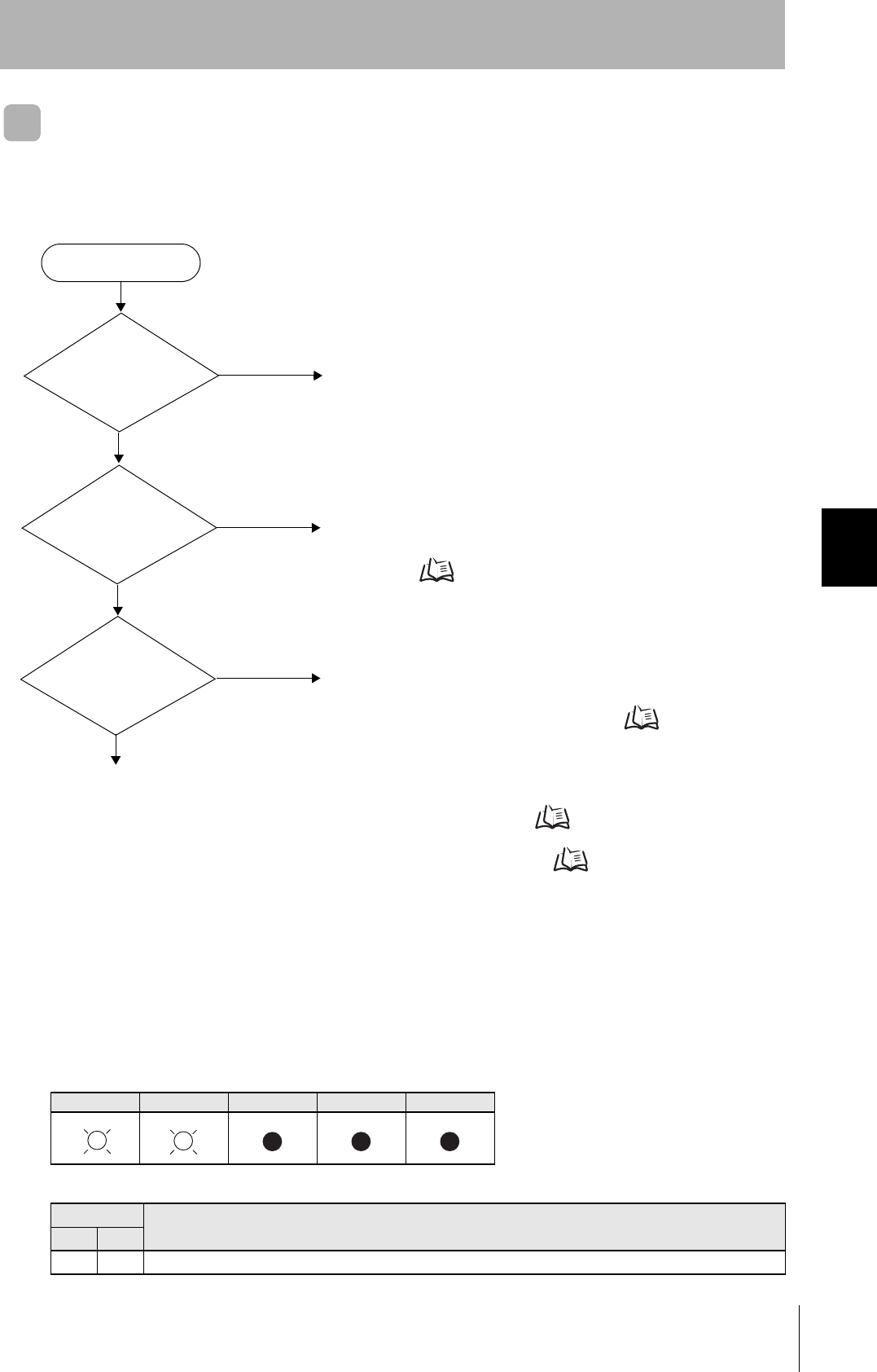
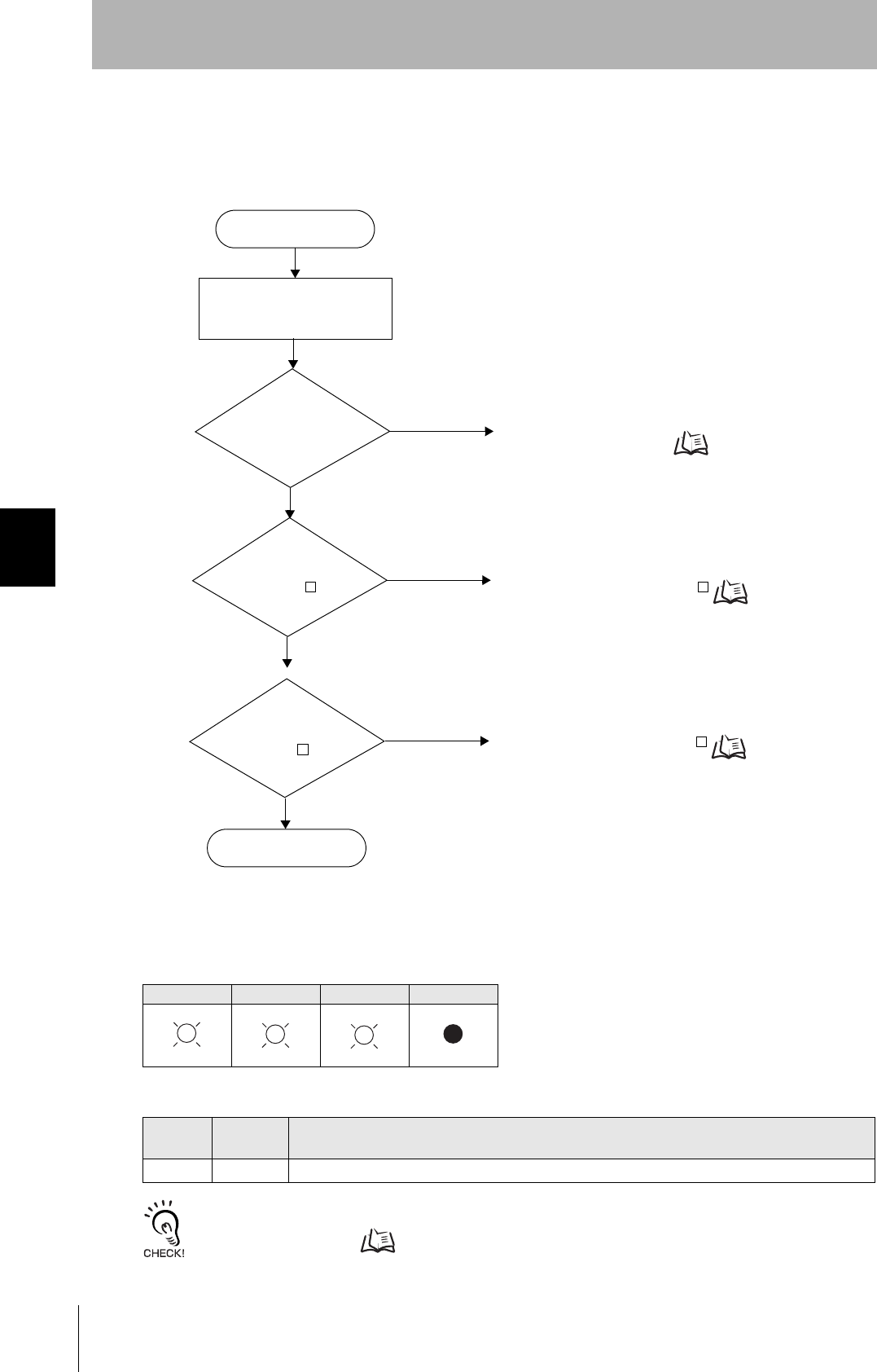
Operation Check Flowchart
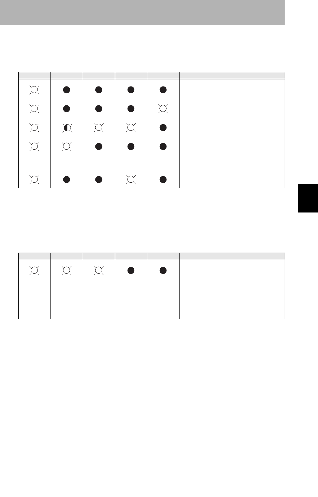
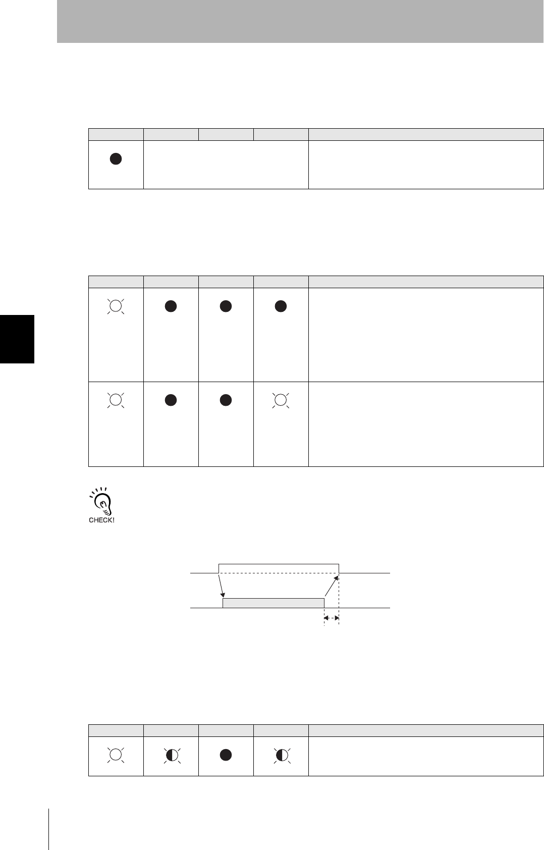
■Normal Operation Mode
• Operating Normally in the Normal Operation Mode
Indicators
POWER OPERATING ALARMS BUSY ERROR
Response
Response Function
S F
— — SSACK="NO"
Response to message
transmission
(SSNAK = other than
“NO”)?
Error occurrence
All indicators lit
or flashing?
POWER indicator
OFF?
No
Yes
No
Yes
No
An error has occurred in the CIDRW Controller power supply.
Check the power supply of the CIDRW power supply.
Check the contents of the response message.
When the CIDRW Controller responds to a message transmis-
sion Refer to page 98.
Yes An error has occurred at the CIDRW Controller.
Check the status of the indicators.
When all the indicators are lit or flashing Refer to page 98.
Check if the settings of the CIDRW Controller and Amplifier Unit are correct.
When the CIDRW Controller Fails to Respond To Messages Sent to It Refer to page 99.
When an Error Unrelated to Message Transmission and Responses Occurs Refer to page 99.
98
SECTION 5
When SECS Is Used
CIDRW System
User’s Manual
SECTION 5
Troubleshooting
• When the CIDRW Controller Responds to a Message Transmission
There is a mistake in the message sent to the CIDRW Controller or the Amplifier Unit settings. After
taking the appropriate corrective action, restart the Controller and the Amplifier Unit and send the mes-
sage again.
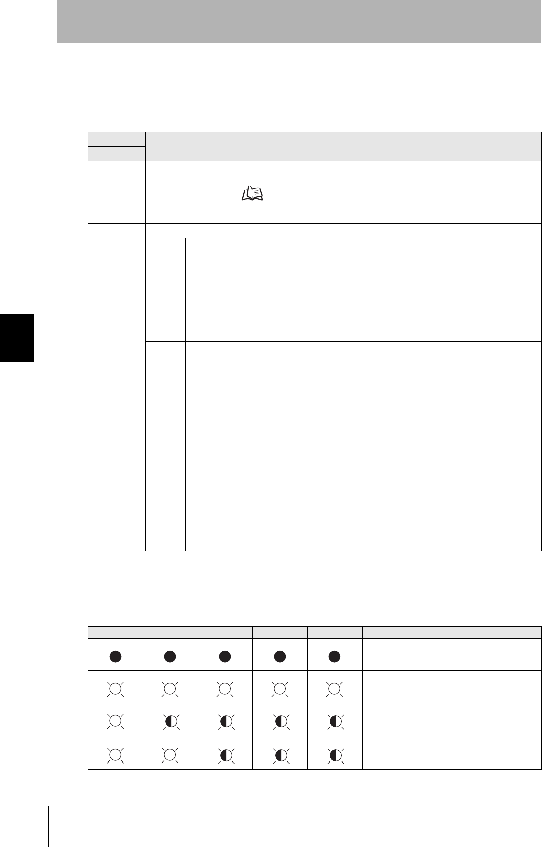
• When All the Indicators are Lit or Flashing
An error has occurred in the CIDRW Controller.
After taking the appropriate corrective action, restart the CIDRW Controller.
Response Main check points
S F
— 0 Status conditions when the message was issued (e.g., a Write ID Request message (S18, F11) was sent in
the operating mode, or the message was sent during initial processing)
Operation Conditions Refer to page 80.
9 7 Message composition: illegal attributes, insufficient items, etc.
Other than
above
Ascertain the cause from the contents of the SSACK response.
CE • Mistake in the details of the items in the message
(The node number of an amplifier that is not set was specified as the TARGET ID, or a segment
name that is not set has been specified for DATASEG.)
• Connection of RS-485 cables between Amplifier Units (failure to detect Amplifier Units)
• Amplifier Unit baud rate settings (failure to detect Amplifier Units)
• Node numbers of the Amplifier Units (The same number is set for more than one Unit, making
detection impossible)
• Cable routing between the host device and CIDRW Controller (influence of background noise)
• Noise levels of the power supply line to the CIDRW Controller
EE • Installation distance/inclination between the ID Tag and CIDRW Head
• Background noise levels of the CIDRW Head
• Installation spacing in relation to CIDRW Heads connected in other CIDRW systems
• When the ID read command is executed, the carrier ID contains non-visible ASCII code.
HE • Mistake in the details of the items in the message
(A segment that does not match the Amplifier Unit specifications has been set; the response
time-out setting is not correct.)
• Connection and wiring of cable between CIDRW Controller and Amplifier Unit
• Power supply to Amplifier Units
• Amplifier Unit terminal resistance settings
• Routing of each cable (influence of background noise)
• Node numbers of the Amplifier Units (the same number is set for more than one Unit)
• Amplifier Unit error (hardware error)
• Noise levels of the power supply line
TE • Type/specifications of the ID Tags used
• Settings of the ID Tags used (lock, etc.)
• Environment of use of the ID Tags (ID Tag breakage due to use in unanticipated ways)
• ID Tag overwrite life
POWER OPERATING ALARMS BUSY ERROR Main check points
• Supply of 24 VDC power
• The CIDRW Controller may be damaged.
• Mode switch setting (Is the setting 0?)
If the error cannot be resolved after checking,
the CIDRW Controller may be damaged.
• The CIDRW Controller may be damaged.
99
CIDRW System
User’s Manual
SECTION 5
When SECS Is Used
SECTION 5
Troubleshooting
• When the CIDRW Controller Fails to Respond To Messages Sent to It
There is a mistake in the CIDRW Controller or Amplifier Unit settings.
After taking the appropriate corrective action, restart the CIDRW Controller and Amplifier Unit.
• When an Error Unrelated to Message Transmission and Responses Occurs
There is a mistake in the settings of the CIDRW Controller and Amplifier Unit.
After taking the appropriate corrective action, restart the CIDRW Controller and Amplifier Unit.
POWER OPERATING ALARMS BUSY ERROR Main check points
• Mode switch setting (Is the setting 0?)
• Cable wiring between the CIDRW Controller
and host device
• Communications conditions for communica-
tions between the CIDRW Controller and host
device (baud rate, character composition, etc.)
• Cable wiring between the CIDRW Controller
and host device
• Node numbers of the Amplifier Units (The
same number is set for more than one Unit.)
POWER OPERATING ALARMS BUSY ERROR Main check points
• Mode switch setting (Is the setting 0?)
• Amplifier Unit baud rate settings
• Node numbers of the Amplifier Units (The
same number is set for more than one Unit.)
• Connection and wiring of cable between
CIDRW Controller and Amplifier Unit
• Amplifier Unit error (hardware error)
• Routing of each cable (influence of back-
ground noise)
100
SECTION 5
When SECS Is Used
CIDRW System
User’s Manual
SECTION 5
Troubleshooting
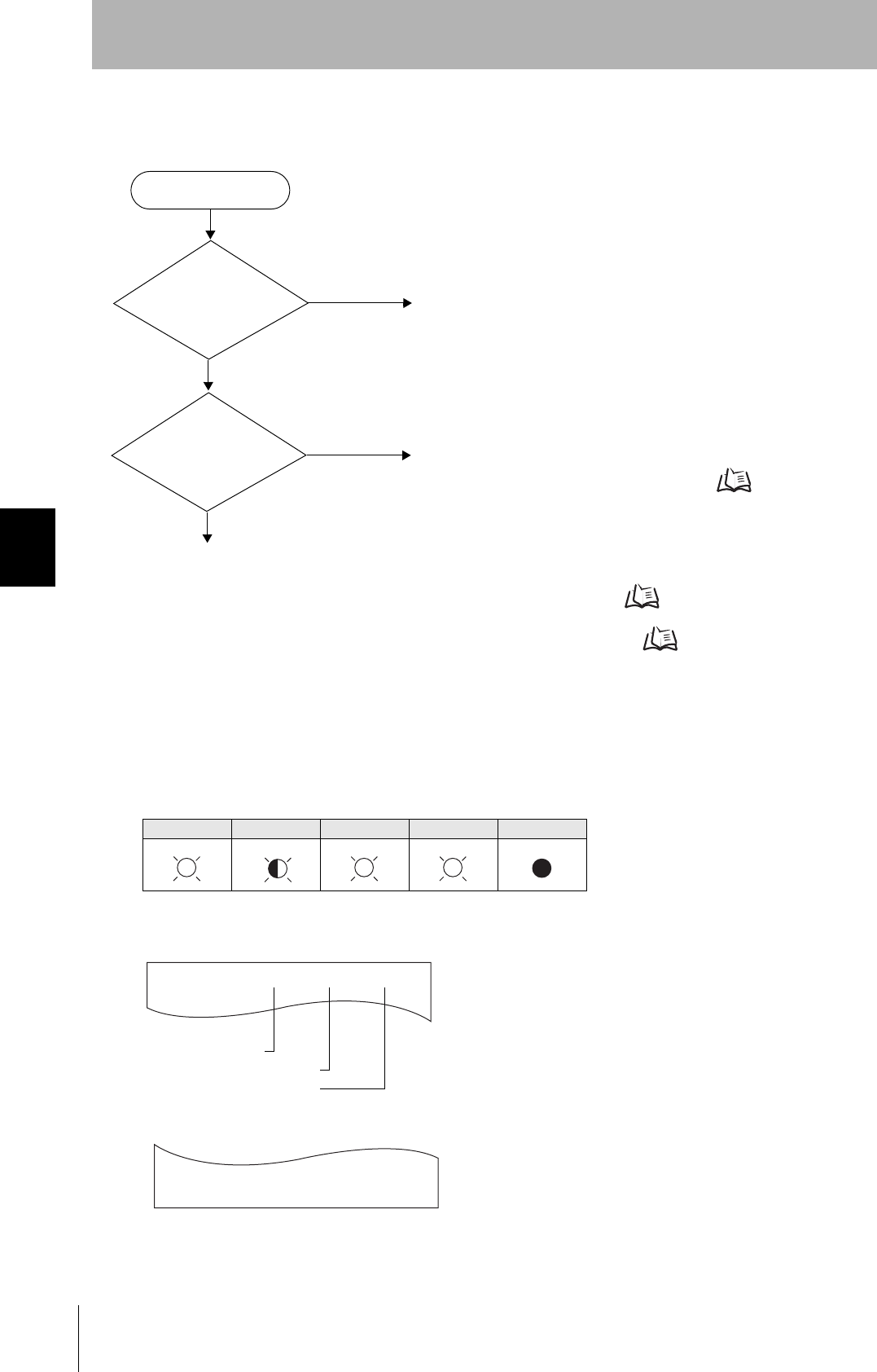
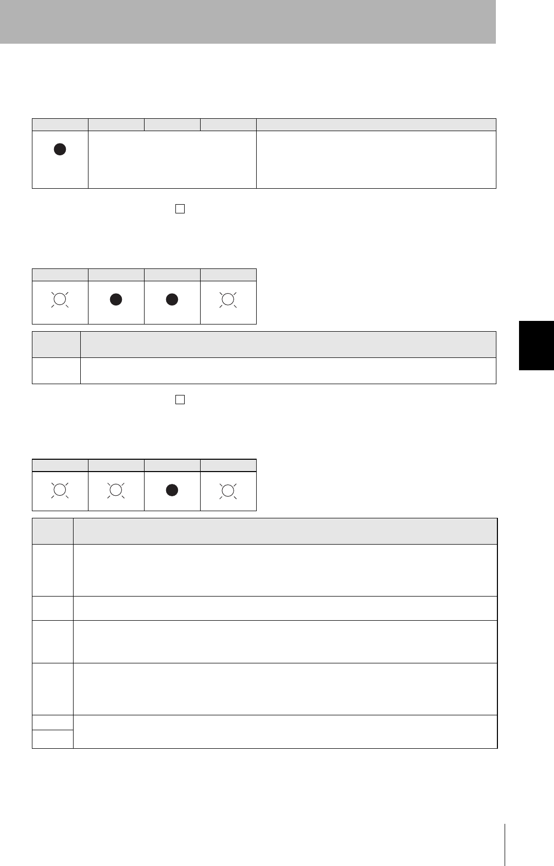
■Setting Mode
• Operating Normally in the Setting mode
Terminal Initial Display of the Host Device after Startup in the Setting mode
Terminal Display When Parameter Setting Has Been Completed without Error
Indicators
POWER OPERATING ALARMS BUSY ERROR
Error occurrence
All indicators lit
or flashing?
POWER indicator
OFF?
No
Yes
No
Yes
An error has occurred in the CIDRW Controller power supply.
Check the power supply of the CIDRW Controller.
An error has occurred at the CIDRW Controller.
Check the status of the indicators.
When all the indicators are lit or flashing Refer to page
101.
Check if the CIDRW Controller settings are correct.
When the CIDRW Controller fails to respond to messages sent to it Refer to page 101.
When an Error Unrelated to Message Transmission and Responses Occurs Refer to page 101.
SETUP_START <L22 ><XXX.XX, YYY.YY>
_
Software Revision Level
Model number
Hardware Revision Level
SETUP_COMPLETE
_
101
CIDRW System
User’s Manual
SECTION 5
When SECS Is Used
SECTION 5
Troubleshooting
• When All the Indicators Are Lit or Flashing
An error has occurred in the CIDRW Controller.
After taking appropriate corrective action, restart the CIDRW Controller and check the indicators.
• When the CIDRW Controller Responds to a Message Transmission
There is a mistake in the CIDRW Controller settings or the sent parameters.
After taking appropriate corrective action, restart the CIDRW Controller and check the indicators.
• When the CIDRW Controller Fails to Respond To Messages Sent to It
There is a mistake in the CIDRW Controller settings or the sent parameters.
After taking appropriate corrective action, restart the CIDRW Controller and check the indicators.
• When an Error Unrelated to Message Transmission and Responses Occurs
There is a mistake in the settings of the CIDRW Controller or Amplifier Unit.
After taking appropriate corrective action, restart the CIDRW Controller and Amplifier Unit and check
the indicators.
POWER OPERATING ALARMS BUSY ERROR Main check points
• Supply of 24 VDC power
• The CIDRW Controller may be damaged.
• Mode switch setting (Is the setting 3?)
If the error cannot be resolved after checking,
the CIDRW Controller may be damaged.
• The CIDRW Controller may be damaged.
POWER OPERATING ALARMS BUSY ERROR Main check points
• Sent parameters (Are the parameters correct?
Are the settings correct?)
Response Contents
SETUP_FAILED [ ] The parameters are not updated. The figure in square brackets [ ] indicates the line number
where the error was first detected. If a parity error is detected in the received characters, this
figure is [0].
POWER OPERATING ALARMS BUSY ERROR Main check points
• Transmission parameters (Are the parameters
correct?)
• Communications conditions for communica-
tions between the CIDRW Controller and the
host device (baud rate, character composition,
etc.)
• Mode switch setting (Is the setting 3?)
POWER OPERATING ALARMS BUSY ERROR Main check points
• Mode switch setting (Is the setting 3?)

102
SECTION 5
When SECS Is Not Used
CIDRW System
User’s Manual
SECTION 5
Troubleshooting
When SECS Is Not Used
Errors are indicated by the presence or absence of a response to an Amplifier Unit command, and by the
indicators.
List of Error Messages
Amplifier Unit Indicators
Type Response
code Name Description
Host communi-
cations error
14 Format error There is a mistake in the command format. (For example, the com-
mand portion is undefined, or the page or address specification is
inappropriate.)
Communications
error between
the CIDRW Head
and ID Tag
70 Communications
error
Noise or another hindrance has occurred during communications with
an ID Tag, and communications cannot be completed normally.
71 Verification error Correct data cannot be written to an ID Tag.
72 No Tag error Either there is no ID Tag in front of the CIDRW Head, or the CIDRW
Head is unable to detect the ID Tag due to environmental factors (e.g.,
noise).
7B Outside write area
error
The ID Tag is at a position where reading is possible but writing is not,
so writing does not complete normally.
7E ID system error (1) The ID Tag is in a status where it cannot execute the command pro-
cessing.
7F ID system error (2) An inapplicable ID Tag has been used.
Name Indications
RUN (green) Turns ON when the Amplifier Unit is in normal operation.
COMM (orange) Turns ON during communications with the host device or during communications with an ID Tag.
NORM (green) Turns ON when the communications finish with no error.
ERROR (red) Turns ON when an error occurs during communications with the host device, or during communications
with an ID Tag.
103
CIDRW System
User’s Manual
SECTION 5
When SECS Is Not Used
SECTION 5
Troubleshooting
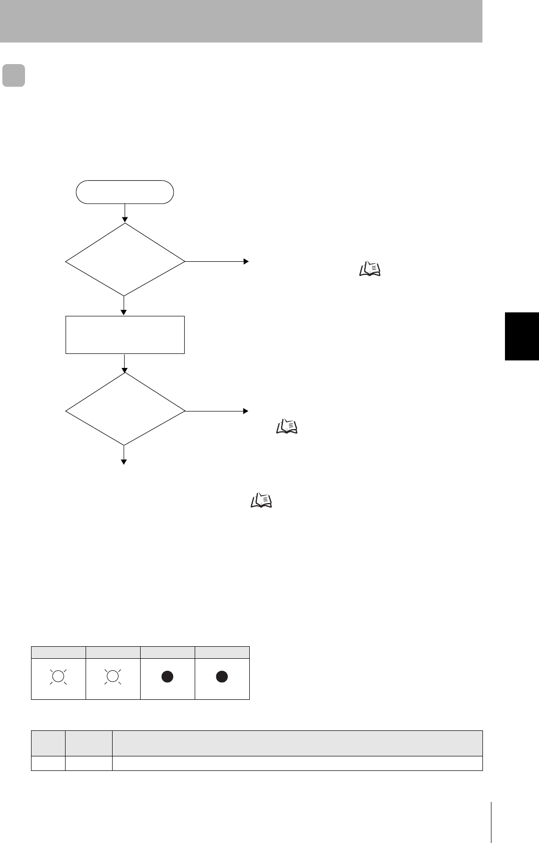
Operation Check Flowchart
■From Installation to Trial Operation
Errors are indicated by whether or not a response to the test command is received and by the status of
the Amplifier Unit indicators.
• If the Test Command Was Received Normally:
Indicators
RUN COMM NORM ERROR
Response Code for the Response
Type Response
code Function
Normal 00 The command was received normally.
Error occurrence
Test command transmission
RUN indicator
OFF?
No
Yes An error has occurred at the Amplifier Unit.
Amplifier Unit error Refer to page 104.
Check if the Amplifier Unit settings are correct.
If There Is No Response to the Command: Refer to page 104.
Response received? Yes Check the nature of the response.
If there is a response to the command
Refer to page 104.
No
(Lights once)
104
SECTION 5
When SECS Is Not Used
CIDRW System
User’s Manual
SECTION 5
Troubleshooting
• Amplifier Unit Error
Check the status of the indicators after transmission of the test command.
After taking appropriate corrective action, restart the Amplifier Unit, send the test command again and
check again.
• If There Is No Response to the Command:
Check the status of the indicators after transmission of the test command.
After taking appropriate corrective action, restart the Amplifier Unit, send the test command again and
check again.
Using RS Signal Control at the Host Device
In a 1:N connection using Link Units, the RS signals generated from the host device by normal control must be input as
CS signals. Turn the RS signals OFF within 15 ms after the completion of data transmission. Correct communications
will not be possible without this control. When using a USB-serial adapter, direct control of the RS signal may not be
possible. Test operation in advance to make sure direct control of the RS signal is correct.
• If There Is a Response to the Command:
Check the status of the indicators after transmission of the test command.
After taking appropriate corrective action, restart the Amplifier Unit, send the test command again and
check again.
RUN COMM NORM ERROR Main check points
—
(If RUN is OFF, the status of the other indica-
tors can be ignored.)
• Influence of background noise (change installation position)
• Amplifier Unit power supply
If the error cannot be resolved after checking, the Amplifier Unit
may be damaged.
RUN COMM NORM ERROR Main check points
• Amplifier Unit baud rate settings
• Node numbers of the Amplifier Units (do not match the node
number in the test command)
• Connection and wiring of the cable between the host device
and Amplifier Unit
• OFF timing of the RS signals between the host device and
Amplifier Unit
• Routing of each cable (influence of background noise)
If the error cannot be resolved after checking, the Amplifier Unit
may be damaged.
• Amplifier Unit baud rate settings
• Amplifier Unit node number setting (More than one Amplifier
Unit may be set to the same node number.)
• Connection and wiring of the cable between the host device
and Amplifier Unit
• Routing of the cables (influence of background noise)
• OFF timing of the RS signals between the host device and
Amplifier Unit
• FCS (frame check sequence) calculation method
RUN COMM NORM ERROR Main check points
• Node numbers of the Amplifier Units (The same number is set
for more than one Unit)
If the error cannot be resolved after checking, the Amplifier
Unit may be damaged.
(Lights once)
SD at host device
RS at host device
ON only during data transmission from the host device
Within 15 ms

105
CIDRW System
User’s Manual
SECTION 5
When SECS Is Not Used
SECTION 5
Troubleshooting
There is a mistake in the command format (number of charac-
ters, character code, etc.).
RUN COMM NORM ERROR Main check points
(Lights once)
106
SECTION 5
When SECS Is Not Used
CIDRW System
User’s Manual
SECTION 5
Troubleshooting
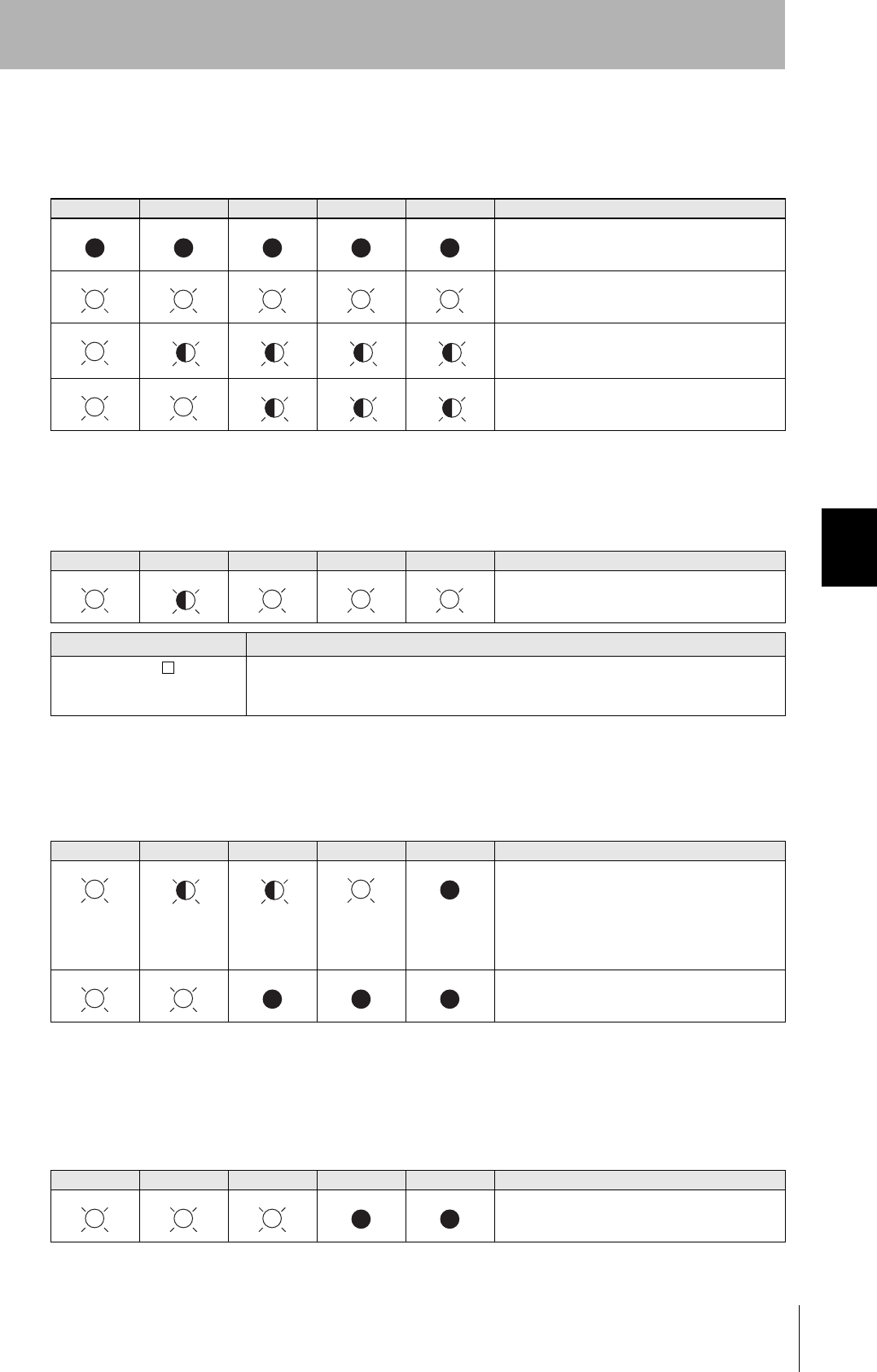
■From Trial Operation to Communications
Errors are indicated by the status of the indicators after transmission of the write command, and by the
response code of the response.
• If the ID Tag Was Processed Normally:
If there is no response to the write command, refer to the From Installation to Trial Operation,
Operation Check Flowchart. Refer to page 103.
Indicators
RUN COMM NORM ERROR
Response Code for the Response
Type Response
code Function
Normal 00 The ID Tag was processed normally.
Error occurrence
Is the response
code 1 ?
No
Yes Check the command format.
If the response code is 1 Refer to page 107.
Yes Communications with the ID Tag has failed.
If the response code is 7 Refer to page 107.
Write command sent
RUN indicator
OFF?
No
Yes An error has occurred at the Amplifier Unit.
Amplifier Unit error Refer to page 107.
Is the response
code 7 ?
Communications OK
No
(Lights once)
(Lights once)
107
CIDRW System
User’s Manual
SECTION 5
When SECS Is Not Used
SECTION 5
Troubleshooting
• Amplifier Unit Error
Check the status of the indicators after transmission of the command. After taking appropriate correc-
tive action, send the write command again and check again.
• If the Response Code is 1 :
There is a host device communications error.
Check the status of the indicators and the response code of the response after transmission of the
command. After taking appropriate corrective action, send the write command again and check again.
• If the Response Code is 7 :
There is a communications error in communications between the CIDRW Head and ID Tag.
Check the status of the indicators and the response code of the response after transmission of the
command.After taking appropriate corrective action, send the write command again and check again.
* The ID Tag has a lock function, but the Amplifier Unit has no function for locking an ID Tag.
RUN COMM NORM ERROR Main check points
—
(If RUN is OFF, the status of the other indica-
tors can be ignored.)
• Influence of background noise (Change installation position)
• Amplifier Unit power supply
If the error cannot be resolved by checking the two points above,
the Amplifier Unit may be damaged.
RUN COMM NORM ERROR
Response
code Main check points
14 Command format
(Command code, page designation, address designation, processed data volume, etc.)
RUN COMM NORM ERROR
Response
code Main check points
70
• Background noise levels of the CIDRW Head (Check the surroundings with the environmental noise level measurement
function)
• Distance to another CIDRW Head
• Influence of background noise (Change installation position)
If the error cannot be resolved after checking, the Amplifier Unit may be damaged.
71 • ID Tag overwrite life (Replace the ID Tag)
• Environment of use of the ID Tags (ID Tag breakage due to use in unanticipated ways)
72 • Connection to the CIDRW Head
• Distance between the ID Tag and CIDRW Head
• CIDRW Head background noise levels (Check the surroundings with the environmental noise level measurement function)
• Distance to another CIDRW Head
7B • Distance between the ID Tag and CIDRW Head
• Background noise levels of the CIDRW Head (Check the surroundings with the environmental noise level measurement
function)
• Distance to another CIDRW Head
• Influence of background noise (Change installation position)
7E • Type/specifications of the ID Tags used
• Settings of the ID Tags used (The ID Tag lock function is used.*)
• Environment of use of the ID Tags (ID Tag breakage due to use in unanticipated ways)
7F
(Lights once)
(Lights once)
(Lights once)

108
SECTION 5
When SECS Is Not Used
CIDRW System
User’s Manual
SECTION 5
Troubleshooting
MEMO

SECTION 6
Appendix
109
CIDRW System
User’s Manual
SECTION 6
Appendix
Specifications and Dimensions 110
System Configuration Examples 115
When SECS Is Not Used 116
Characteristic Data According to Conditions of Use 117
ID Tag Memory Maps 147
Regular Inspection 148
SECS Protocol Specifications 149
ASCII Code Table 154
Protective Construction 155
110
SECTION 6
Specifications and Dimensions
CIDRW System
User’s Manual
SECTION 6
Appendix
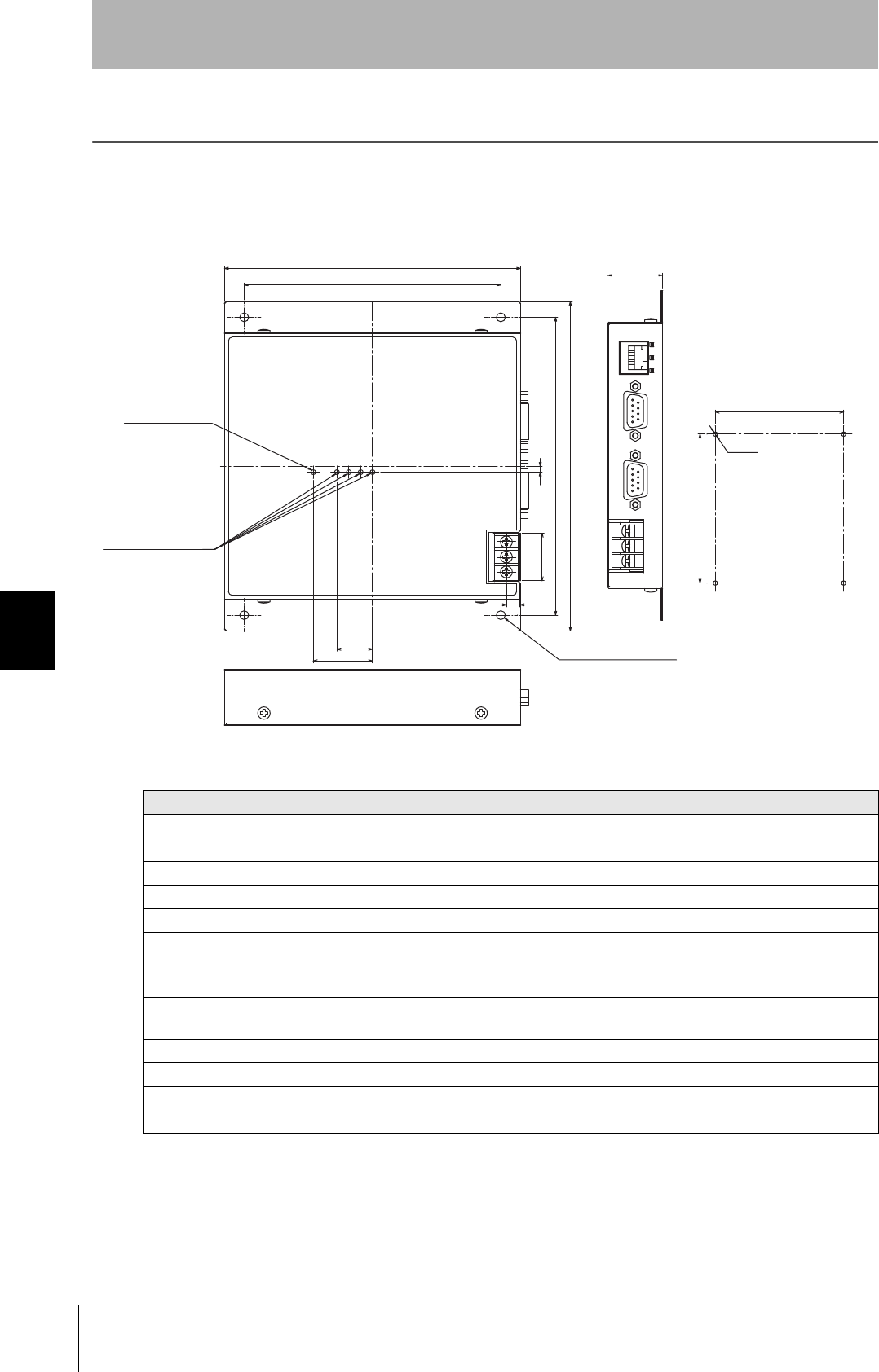
Specifications and Dimensions
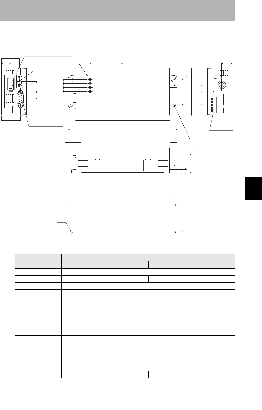
Controller
V700-L22
Item Specifications
Power supply voltage 24 VDC +10% -15%
Current consumption 150 mA max. (inrush current: approx. 10 A max.)
Ambient temperature Operating: 0 to +40°C Storage: -15 to +65°C (with no icing)
Ambient humidity Operating: 10% to 85% Storage: 10% to 95% (with no condensation)
Degree of protection IP20 (IEC60529)
Insulation resistance 50 MΩ min. between power supply terminals and the frame ground terminal (500 VDC M)
Dielectric strength Leak current not to exceed 3.5 mA on application of 500 VAC (50/60 Hz for 1 minute) between both
power supply terminals and the frame ground terminal
Vibration resistance Frequency: 10 to 150 Hz; double amplitude: 0.20 mm; acceleration: 15 m/s2 for
8 minutes, 10 times each in X, Y, and Z directions
Shock resistance Shock of 150 m/s2 in X, Y, and Z directions, 3 times each for 18 repetitions
Ground Ground to 100 Ω or less.
Case material SECC (coating)
Weight Approx. 580 g
150
167
28
130
3
151
30
P6X3
130±0.2
151±0.2
4-M4
24
7
(1:2)
4-φ4.5
(Unit: mm)
Mounting dimensions
Power indicator
Operation indicators
(mounting holes)
Four, 4.5-dia. holes
CIDRW System
User’s Manual
SECTION 6
Specifications and Dimensions
SECTION 6
Appendix
111
Amplifier Units
V640-HAM11-V3 and V640-HAM11-L
Item Specifications
V640-HAM11-V3 V640-HAM11-L
Power supply voltage 24 VDC +10% -15%
Current consumption 150 mA max. 400 mA max.
Ambient temperature Operating: 0 to +40°C Storage: -15 to +65°C (with no icing)
Ambient humidity Operating/Storage: 35% to 85% (with no condensation)
Degree of protection IP20 (IEC60529 standard)
Insulation resistance 20 MΩ min. between power supply terminals and the frame ground terminal (100 VDC M)
Dielectric strength Leak current not to exceed 5 mA on application of 1000 VAC (50/60 Hz for 1 minute) between both
power supply terminals and the frame ground terminal
Vibration resistance Frequency: 10 to 150 Hz; double amplitude: 0.20 mm; acceleration: 15 m/s2 for
8 minutes, 10 times each in X, Y, and Z directions
Shock resistance Shock of 150 m/s2 in X, Y, and Z directions, 3 times each for 18 repetitions
Ground Ground to 100 Ω or less.
Case material PC/ABS resin
Shape 80×185×43 mm (W×D×H)
Weight Approx. 250 g
CIDRW Head V640-HS61 V640-HS62
160
175
185
55.5
46
56
80
6.86.86.80.6
(4.2)
(1)
(11.5)
(32.5)
43
5
(5.7)
(13)
(17.75)(12)
(32.5)
(30.2)
(15.8)
(12)
(18.2)
(22.5)
4-M4
175±0.5
46±0.5
DIP switch
(Unit: mm)
Mounting dimensions
Four, 4.5-dia. holes
DC power supply connector
RS-485 connector
RS-232C connector
Four operation indicators
112
SECTION 6
Specifications and Dimensions
CIDRW System
User’s Manual
SECTION 6
Appendix
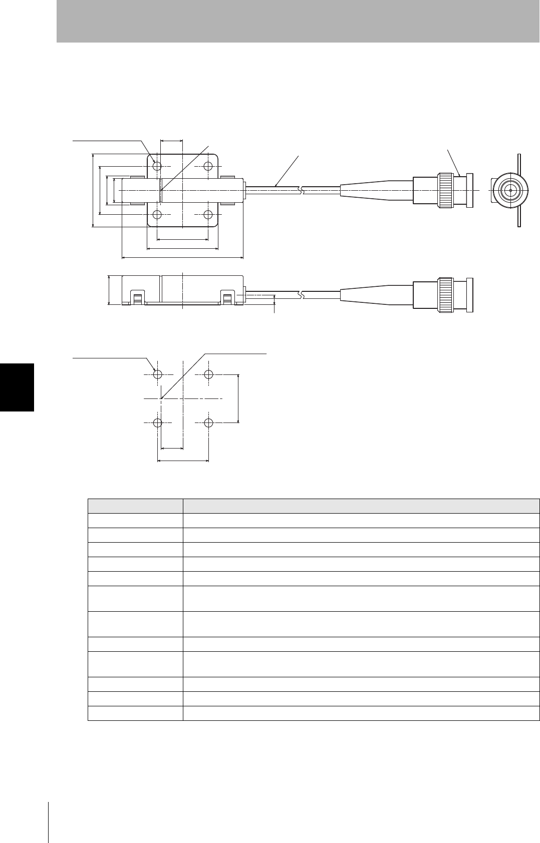
CIDRW Heads
V640-HS61
Item Specifications
Transmission frequency 134 kHz
Ambient temperature Operating: 0 to +40°C Storage: -15 to +65°C (with no icing)
Ambient humidity Operating/Storage: 35% to 85% (with no condensation)
Degree of protection IP60 (IEC60529)
Insulation resistance 20 MΩ min. between all terminals and the case (100 VDC M)
Dielectric strength Leak current not to exceed 5 mA on application of 1000 VAC (50/60 Hz for 1 minute) between all
terminals and the case
Vibration resistance Frequency: 10 to 150 Hz; double amplitude: 0.20 mm; acceleration: 15 m/s2 for
8 minutes, 10 times each in X, Y, and Z directions
Shock resistance Shock of 150 m/s2 in X, Y, and Z directions, 3 times each for 18 repetitions
Casing material ABS/epoxy resin
Stainless steel mount
Weight Approx. 70 g
Cable length 2 m
Cable specification 3-mm-dia. coaxial cable
Coaxial cable 3.0 dia., standard length 2 m
(Unit: mm)
Connector
Antenna center
Antenna center
Mounting dimensions
Four M3 or 3.5-dia. holes
Four, 3.5-dia. holes
CIDRW System
User’s Manual
SECTION 6
Specifications and Dimensions
SECTION 6
Appendix
113
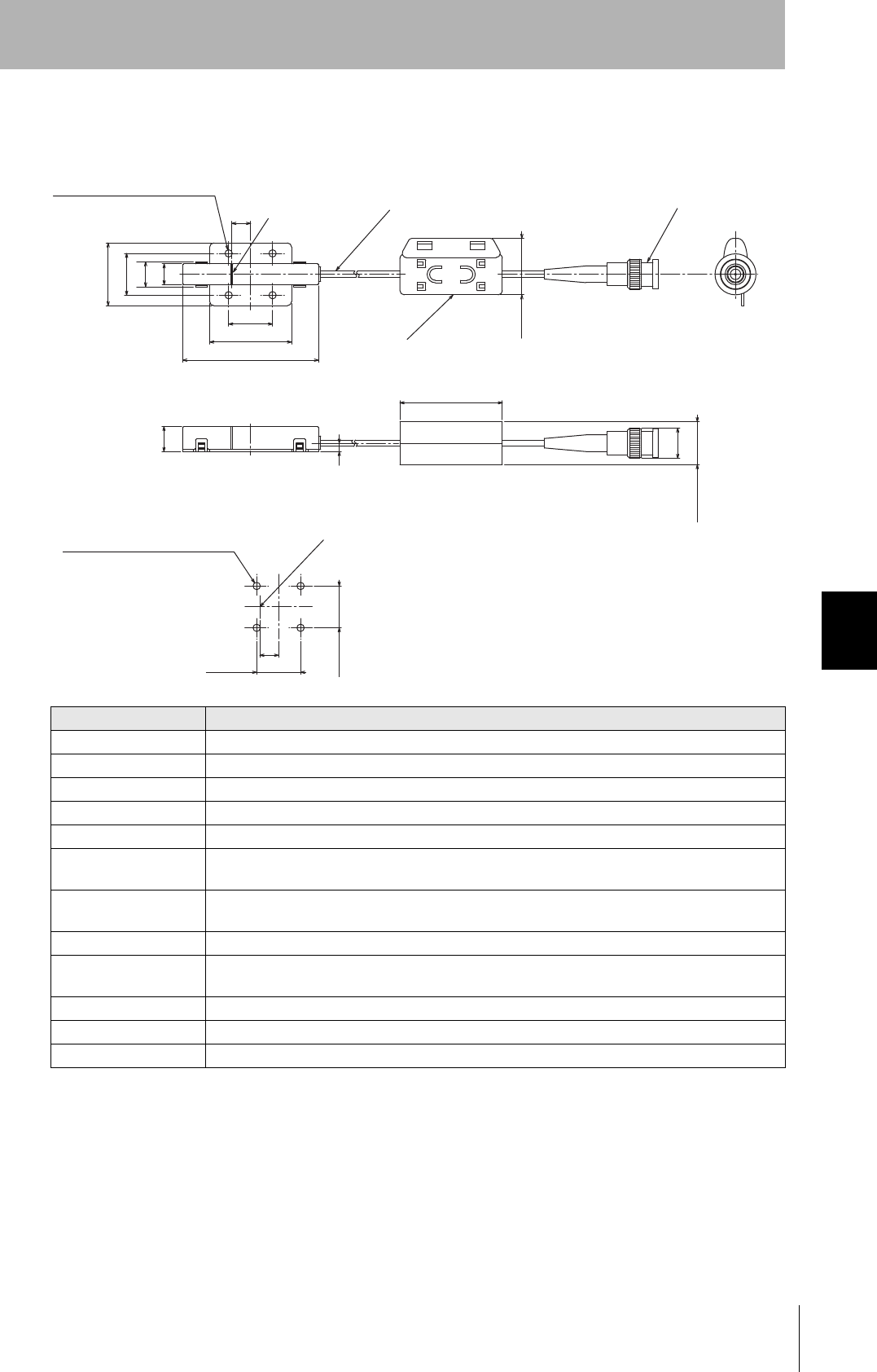
V640-HS62
Item Specifications
Transmission frequency 134 kHz
Ambient temperature Operating: 0 to +40°C Storage: -15 to +65°C (with no icing)
Ambient humidity Operating/Storage: 35% to 85% (with no condensation)
Degree of protection IP60 (IEC60529)
Insulation resistance 20 MΩ min. between all terminals and the case (100 VDC M)
Dielectric strength Leak current not to exceed 5 mA on application of 1000 VAC (50/60 Hz for 1 minute) between all
terminals and the case
Vibration resistance Frequency: 10 to 150 Hz; double amplitude: 0.20 mm; acceleration: 15 m/s2 for
8 minutes, 10 times each in X, Y, and Z directions
Shock resistance Shock of 150 m/s2 in X, Y, and Z directions, 3 times each for 18 repetitions
Casing material ABS/epoxy resin
Stainless steel mount
Weight Approx. 100 g
Cable length 1.9 m
Cable specification 3-mm-dia. coaxial cable
30
20
12
10
9
65
39.2
21
Max.28
12
4
49
14.5
Max.20.5
9
21±0.2
20±0.2
Ferrite core
(Unit: mm)
Connector
Coaxial cable, Dia.: 3.0, Length: 1.9 m
Center of coil
Mounting Hole Dimensions
Four M3 or 3.5-dia. holes
Four 3.5-dia. (mounting holes)
Center of coil
114
SECTION 6
Specifications and Dimensions
CIDRW System
User’s Manual
SECTION 6
Appendix
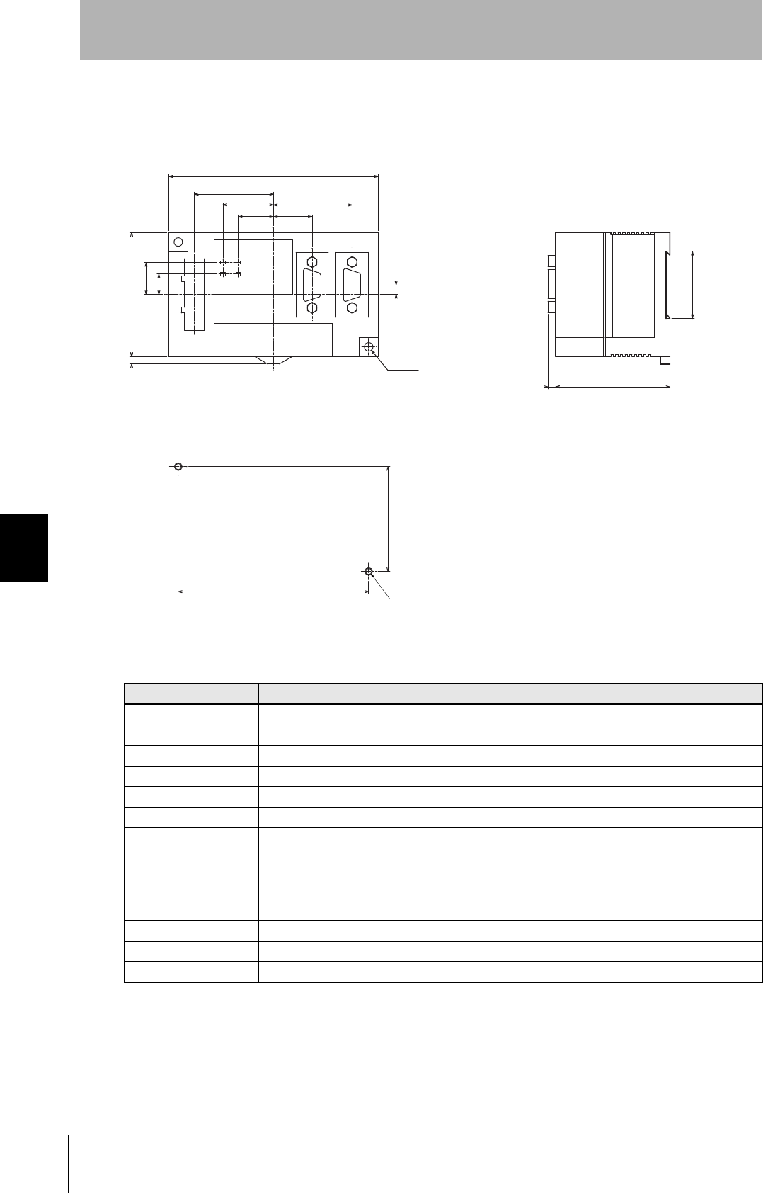
Link Unit
V700-L11
Item Specifications
Power supply voltage 24 VDC +10% -15%
Current consumption 250 mA max. (inrush current: approx. 10 A)
Ambient temperature Operating: 0 to +40°C Storage: -15 to +50°C (with no icing)
Ambient humidity Operating/Storage: 35% to 85% (with no condensation)
Degree of protection IP20 (IEC60529)
Insulation resistance 50 MΩ min. between power supply terminals and the frame ground terminal (500 VDC M)
Dielectric strength Leak current not to exceed 5 mA on application of 1000 VAC (50/60 Hz for 1 minute) between
power supply terminals and the frame ground terminal
Vibration resistance Frequency: 10 to 150 Hz; double amplitude: 0.20 mm; acceleration: 15 m/s2 for 8 minutes, 10 times
each in X, Y, and Z directions
Shock resistance Shock of 150 m/s2 in X, Y, and Z directions, 3 times each for 18 repetitions
Ground Ground to 100 Ω or less.
Case material PC/ABS resin
Weight Approx. 200 g
65
4
110
60
35.2
18.5
26.5
41.5
20.3
41.3
10.7
16.7
5
55±0.2
100±0.2
4
2-φ4.5
2-M4 OR φ4.2
(Unit: mm)
Mounting dimensions
Two M4 or 4.2-dia. holes
Two, 4.5-dia. holes
CIDRW System
User’s Manual
SECTION 6
System Configuration Examples
SECTION 6
Appendix
115
System Configuration Examples
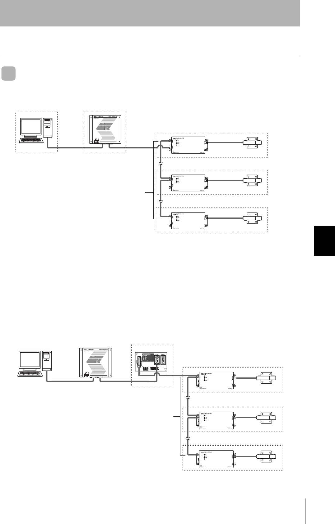
When SECS Is Used
Communications with the host device is possible using the SECS protocol.
With the above system configuration, the Amplifier Unit connected directly to the CIDRW Controller
converts signals from RS-232C to RS-485. If this Amplifier Unit is removed, communications will not be
possible with the other Amplifier Units. If the Amplifier Unit connected directly to the CIDRW Controller
must be removed while the system is operating, insert a Link Unit (V700-L11) between the CIDRW
Controller and the first Amplifier Unit. If an Amplifier Unit on the end of the network is removed, be sure
to turn ON the terminating resistance on the Amplifier Unit that will end up on the end of the network
while the Amplifier Unit is removed.
Host
The CIDRW Heads are the
antennas for reading the car-
rier IDs from the ID Tags and
writing the carrier IDs.
The Amplifier Units con-
trol the CIDRW Heads.
Up to 31 Units can be
connected.
This is a host computer,
equipment controller, etc.
CIDRW Head
V640-HS61
V640-HS62
Amplifier Unit
V640-HAM11-V3
V640-HAM11-L
CIDRW Controller
V700-L22
Multiple Amplifier Units
are controlled in
response to commands
(SECS) from the host
device.
RS-232C
SECS I/II
50 m max.
RS-485
RS-232C
RS-232C
SECS I/II
RS-232C
Link Unit
V700-L11
Just the relevant Amplifier Unit can be
removed and replaced while the power
remains on.
50 m max.
RS-485
Up to 31 Units can be connected.
116
SECTION 6
System Configuration Examples
CIDRW System
User’s Manual
SECTION 6
Appendix
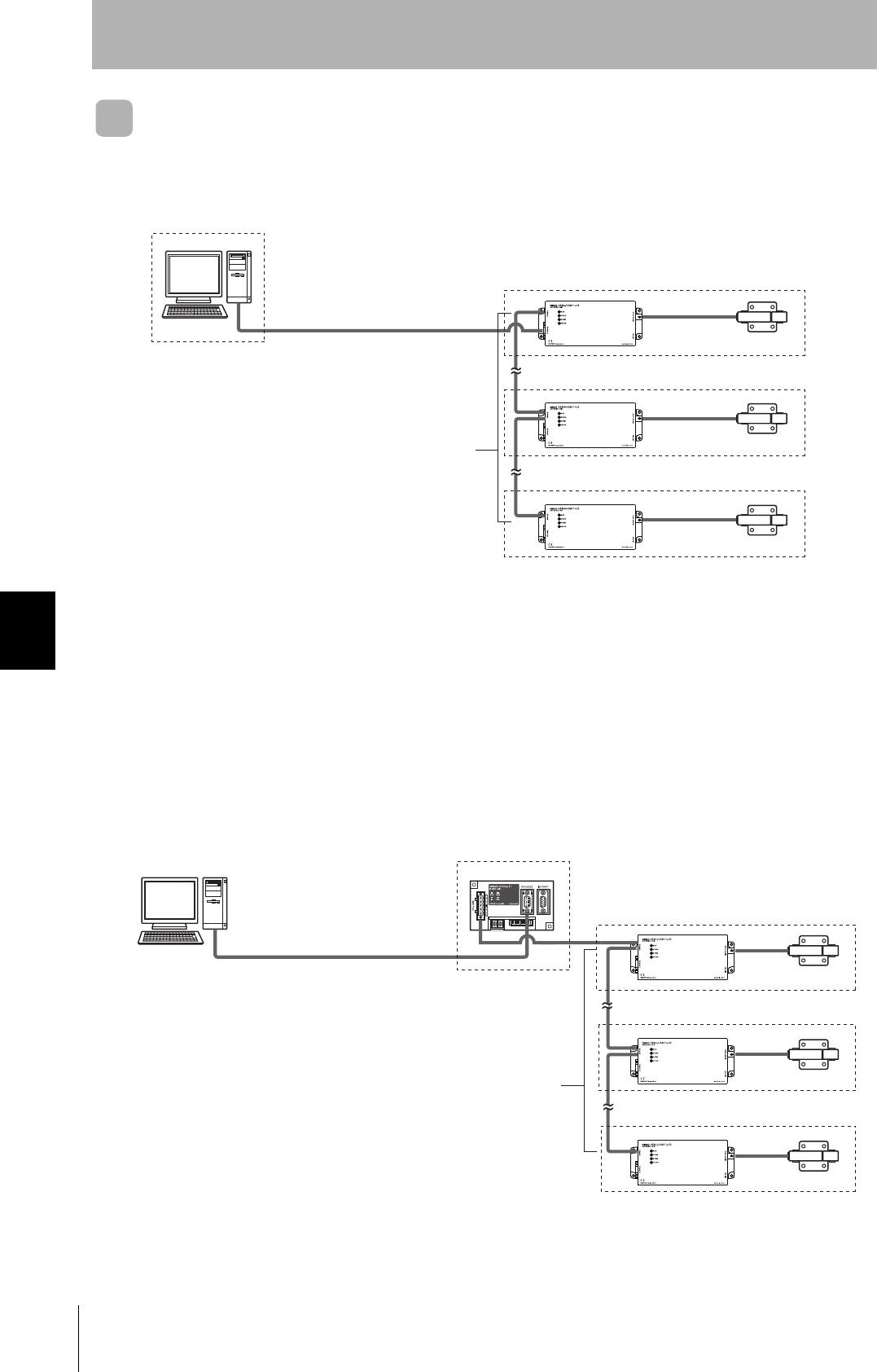
When SECS Is Not Used
Communications with the host device follow the OMRON proprietary protocol.
The Amplifier Units are connected directly to the host device without using a CIDRW Controller.
With the above system configuration, the Amplifier Unit connected directly to the CIDRW Controller
converts signals from RS-232C to RS-485. If this Amplifier Unit is removed, communications will not be
possible with the other Amplifier Units. If the Amplifier Unit connected directly to the CIDRW Controller
must be removed while the system is operating, insert a Link Unit (V700-L11) between the CIDRW
Controller and the first Amplifier Unit. If an Amplifier Unit on the end of the network is removed, be sure
to turn ON the terminating resistance on the Amplifier Unit that will end up on the end of the network
while the Amplifier Unit is removed.
Host
The CIDRW Heads are the
antennas for reading the car-
rier IDs from the ID Tags and
writing the carrier IDs.
The Amplifier Units con-
trol the CIDRW Heads.
Up to 31 Units can be
connected.
This is a host com-
puter, equipment
controller, etc.
Amplifier Units
V640-HAM11-V3
V640-HAM11-L
RS-232C
OMRON original protocol
50 m max.
CIDRW Heads
V640-HS61
V640-HS62
RS-485
50 m max.
Link Unit
V700-L11
Just the relevant Amplifier Unit can be
removed and replaced while the power
remains on.
RS-485
Up to 31 Units can be connected.
RS-232C
OMRON original protocol
CIDRW System
User’s Manual
SECTION 6
Characteristic Data According to Conditions of Use
SECTION 6
Appendix
117
Characteristic Data According to Conditions of Use
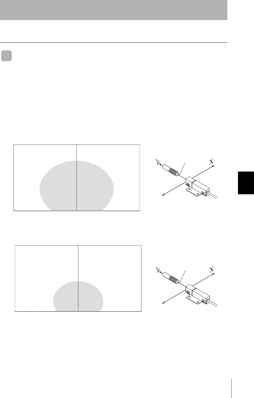
Maps of Communications Areas (Reference Only)
The figures given below for communications areas (communications distances) are reference values
only. The maps of communications areas will vary according to the ID Tags that you use, the back-
ground metals, the ambient noise, the effects of temperature and so on, and should be thoroughly con-
firmed on installation. The direction of the ID Tags will affect communications performance. Check the
direction of the coils in the ID Tags before using the ID Tags.
■V640-HAM11-V3
• Coaxial Mounting (RI-TRP-DR2B)
• READ
• WRITE
0
10
20
30
40
50
60
70
80
90
100
-80 -70 -60 -50 -40 -30 -20 -10 0 10 20 30 40 50 60 70 80
Communications Area (READ)
Distance in Y direction (mm)
Distance in X direction (mm)
Measurement point
0
10
20
30
40
50
60
70
80
90
100
-80 -70 -60 -50 -40 -30 -20 -10 0 10 20 30 40 50 60 70 80
Communications Area (WRITE)
Distance in Y direction (mm)
Distance in X direction (mm)
Measurement point
118
SECTION 6
Characteristic Data According to Conditions of Use
CIDRW System
User’s Manual
SECTION 6
Appendix
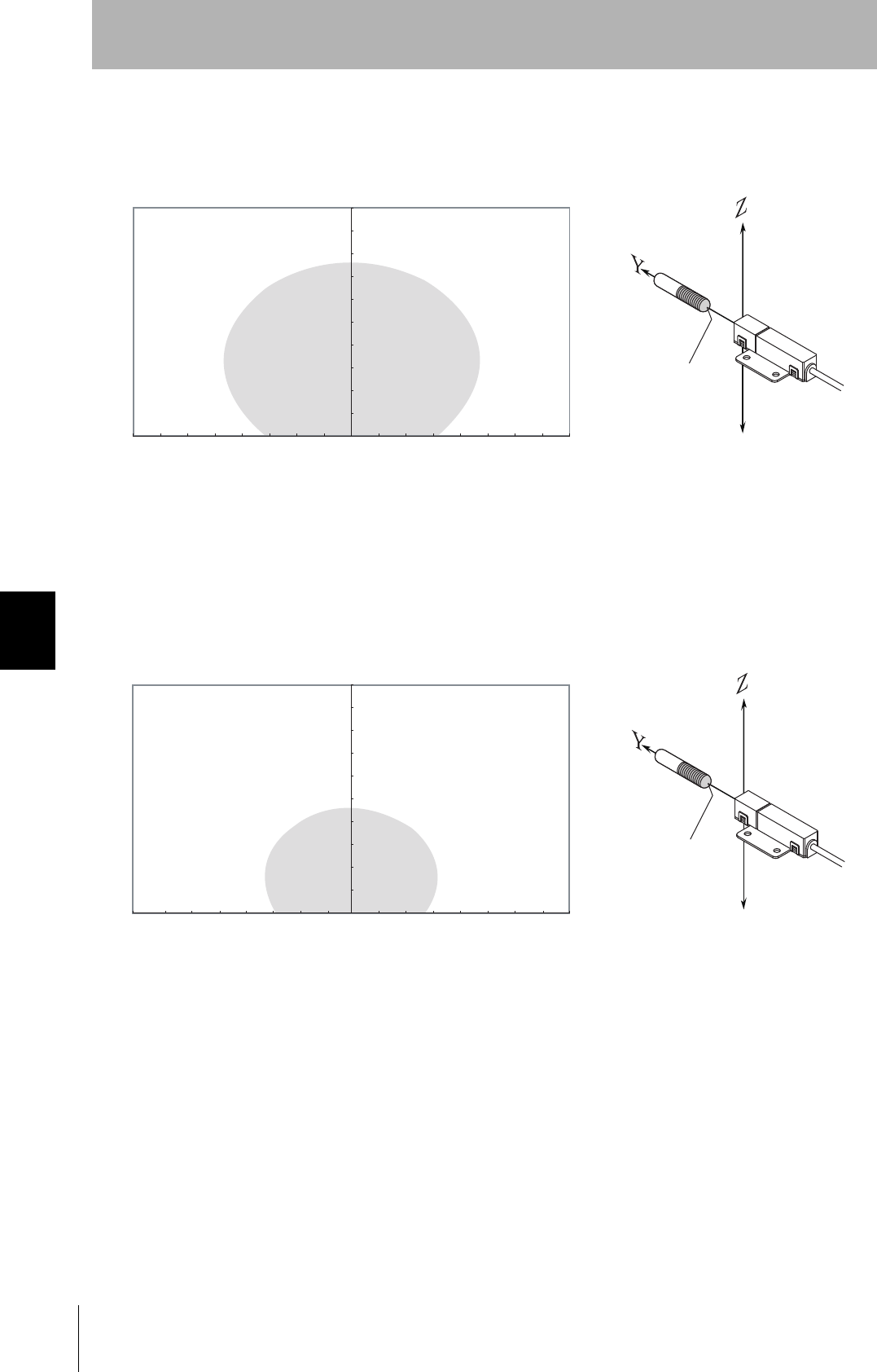
• Coaxial Mounting (RI-TRP-DR2B)
• READ
• WRITE
0
10
20
30
40
50
60
70
80
90
100
-80 -70 -60 -50 -40 -30 -20 -10 0 10 20 30 40 50 60 70 80
Communications Area (READ)
Distance in Z direction (mm)
Measurement point
Distance in Y direction (mm)
0
10
20
30
40
50
60
70
80
90
100
-80 -70 -60 -50 -40 -30 -20 -10 0 10 20 30 40 50 60 70 80
Communications Area (WRITE)
Distance in Z direction (mm)
Measurement point
Distance in Y direction (mm)