Omron V640HAM11 Carrier ID Reader/Writer (RFID) User Manual Z308 E1 01
Omron Corporation Carrier ID Reader/Writer (RFID) Z308 E1 01
Omron >
Contents
- 1. User manual(ETN)
- 2. User manual(V3)
- 3. User manual2& 65288;ETN)
- 4. User manual2& 65288;V3)
User manual(ETN)

CIDRW SYSTEM
V640 SERIES
USER'S MANUAL
Cat. No. Z308-E1-01
AMPLIFIER UNITS
V640-HAM11-ETN
V640-HAM11-L-ETN
CIDRW HEADS
V640-HS61
V640-HS62

Introduction
Thank you for purchasing the V640-series CIDRW System.
Please observe the following points when operating the V640-series CIDRW System:
• Please read and understand the contents of this manual before using the system.
• After reading this manual, store it in a convenient location for easy reference whenever necessary.

ÇÕǹÇ?Ç ëÊ 1 èÕ ëÊ 2 èÕ ëÊ 3 èÕ ëÊ 4 èÕ
INTRODUCTION
SECTION 1 SECTION 2 SECTION 3 SECTION 4 SECTION 5 SECTION 6 SECTION 7
Introduction
SECTION 1
SECTION 2
SECTION 3
SECTION 4
SECTION 5
SECTION 6
SECTION 7
Table of Contents/Precautions in Using the Products
Product Outline
Installation and Connections/Wiring
Preparing for Communications
Reading from/Writing to ID Tags
Browser Interface
Troubleshooting
CIDRW System
V640-HAM11-ETN Amplifier Unit
V640-HAM11-L-ETN Amplifier Unit
V640-HS61 CIDRW Head
V640-HS62 CIDRW Head
User's Manual
Appendix

2
INTRODUCTION
Precautions in using the product
CIDRW System
User’s Manual
INTRODUCTION
READ AND UNDERSTAND THIS DOCUMENT
Please read and understand this document before using the products. Please consult your OMRON representative if you
have any questions or comments.
WARRANTY
OMRON’s exclusive warranty is that the products are free from defects in materials and workmanship for a period of one
year (or other period if specified) from date of sale by OMRON.
OMRON MAKES NO WARRANTY OR REPRESENTATION, EXPRESS OR IMPLIED, REGARDING NON-
INFRINGEMENT, MERCHANTABILITY, OR FITNESS FOR PARTICULAR PURPOSE OF THE PRODUCTS. ANY
BUYER OR USER ACKNOWLEDGES THAT THE BUYER OR USER ALONE HAS DETERMINED THAT THE
PRODUCTS WILL SUITABLY MEET THE REQUIREMENTS OF THEIR INTENDED USE. OMRON DISCLAIMS ALL
OTHER WARRANTIES, EXPRESS OR IMPLIED.
LIMITATIONS OF LIABILITY
OMRON SHALL NOT BE RESPONSIBLE FOR SPECIAL, INDIRECT, OR CONSEQUENTIAL DAMAGES, LOSS OF
PROFITS OR COMMERCIAL LOSS IN ANY WAY CONNECTED WITH THE PRODUCTS, WHETHER SUCH CLAIM IS
BASED ON CONTRACT, WARRANTY, NEGLIGENCE, OR STRICT LIABILITY.
In no event shall responsibility of OMRON for any act exceed the individual price of the product on which liability is
asserted.
IN NO EVENT SHALL OMRON BE RESPONSIBLE FOR WARRANTY, REPAIR, OR OTHER CLAIMS REGARDING THE
PRODUCTS UNLESS OMRON’S ANALYSIS CONFIRMS THAT THE PRODUCTS WERE PROPERLY HANDLED,
STORED, INSTALLED, AND MAINTAINED AND NOT SUBJECT TO CONTAMINATION, ABUSE, MISUSE, OR
INAPPROPRIATE MODIFICATION OR REPAIR.
SUITABILITY FOR USE
THE PRODUCTS CONTAINED IN THIS DOCUMENT ARE NOT SAFETY RATED. THEY ARE NOT DESIGNED OR
RATED FOR ENSURING SAFETY OF PERSONS, AND SHOULD NOT BE RELIED UPON AS A SAFETY COMPONENT
OR PROTECTIVE DEVICE FOR SUCH PURPOSES. Please refer to separate catalogs for OMRON's safety rated
products.
OMRON shall not be responsible for conformity with any standards, codes, or regulations that apply to the combination of
products in the customer’s application or use of the product.
At the customer’s request, OMRON will provide applicable third party certification documents identifying ratings and
limitations of use that apply to the products. This information by itself is not sufficient for a complete determination of the
suitability of the products in combination with the end product, machine, system, or other application or use.
The following are some examples of applications for which particular attention must be given. This is not intended to be an
exhaustive list of all possible uses of the products, nor is it intended to imply that the uses listed may be suitable for the
products:
• Outdoor use, uses involving potential chemical contamination or electrical interference, or conditions or uses not
described in this document.
• Nuclear energy control systems, combustion systems, railroad systems, aviation systems, medical equipment,
amusement machines, vehicles, safety equipment, and installations subject to separate industry or government
regulations.
• Systems, machines, and equipment that could present a risk to life or property.
Please know and observe all prohibitions of use applicable to the products.
NEVER USE THE PRODUCTS FOR AN APPLICATION INVOLVING SERIOUS RISK TO LIFE OR PROPERTY
WITHOUT ENSURING THAT THE SYSTEM AS A WHOLE HAS BEEN DESIGNED TO ADDRESS THE RISKS, AND
THAT THE OMRON PRODUCT IS PROPERLY RATED AND INSTALLED FOR THE INTENDED USE WITHIN THE
OVERALL EQUIPMENT OR SYSTEM.

3
CIDRW System
User’s Manual
INTRODUCTION
Precautions in using the product
INTRODUCTION
PERFORMANCE DATA
Performance data given in this document is provided as a guide for the user in determining suitability and does not
constitute a warranty. It may represent the result of OMRON’s test conditions, and the users must correlate it to actual
application requirements. Actual performance is subject to the OMRON Warranty and Limitations of Liability.
CHANGE IN SPECIFICATIONS
Product specifications and accessories may be changed at any time based on improvements and other reasons.
It is our practice to change model numbers when published ratings or features are changed, or when significant
construction changes are made. However, some specifications of the product may be changed without any notice. When
in doubt, special model numbers may be assigned to fix or establish key specifications for your application on your
request. Please consult with your OMRON representative at any time to confirm actual specifications of purchased
products.
DIMENSIONS AND WEIGHTS
Dimensions and weights are nominal and are not to be used for manufacturing purposes, even when tolerances are
shown.
ERRORS AND OMISSIONS
The information in this document has been carefully checked and is believed to be accurate; however, no responsibility is
assumed for clerical, typographical, or proofreading errors, or omissions.
PROGRAMMABLE PRODUCTS
OMRON shall not be responsible for the user’s programming of a programmable product, or any consequence thereof.
COPYRIGHT AND COPY PERMISSION
This document shall not be copied for sales or promotions without permission.
This document is protected by copyright and is intended solely for use in conjunction with the product. Please notify us
before copying or reproducing this document in any manner, for any other purpose. If copying or transmitting this
document to another, please copy or transmit it in its entirety.

4
INTRODUCTION
Precautions in using the product
CIDRW System
User’s Manual
INTRODUCTION
Applicable Standards
The CIDRW System complies with the following international regulations and standards.
1. USA
FCC NOTICE
This device complies with part 15 of the FCC Rules. Operation is subject to the following two conditions:
(1) This device may not cause harmful interference.
(2) This device must accept any interference received, including interference that may cause undesired opera-
tion.
FCC WARNING
Changes or modifications not expressly approved by the party responsible for compliance could void the user's
authority to operate the equipment.
Do not remove the ferrite core (TDK-EPC Type ZCAT2749-0430C:V640-HS62) installed on the cables to suppress RF
interference.
FCC Part15 subpart B
NOTICE
This equipment has been tested and found to comply with the limits for a Class A digital device, pursuant to part15 of
the FCC Rules. These limits are designed to provide reasonable protection against harmful interference when the
equipment is operated in a commercial environment.
This equipment generates, uses and can radiate radio frequency energy and, if not installed and used in accordance
with the instructions, may cause harmful interference to radio communications. Operation of this equipment in a
residential area is likely to cause harmful interference in which case the user will be required to correct the interference
at his own expense.
CAUTION
This device must be professionally installed.
2. Canada
This device complies with RSS-Gen of IC (Industry Canada) Rules.
Operation is subject to the following two conditions: (1) this device may not cause harmful interference, and (2)
this device must accept any interference received, including interference that may cause undesired operation.
ICES-003
This class A digital apparatus complies with Canadian ICES-003.
Cet appareil numerique de la classe A est conforme a la norme NMB-003 du Canada.
CIDRW Amplifier Unit CIDRW Head
FCC Part 15 Subpart C
FCC ID: E4EV640HAM11
V640-HAM11-ETN V640-HS61
FCC Part 15 Subpart C
FCC ID: E4EV640HAM11L
V640-HAM11-L-ETN V640-HS62
CIDRW Amplifier Unit CIDRW Head
IC ID: 850J-V64HAM11 V640-HAM11-ETN V640-HS61
IC ID: 850J-V64HM11L V640-HAM11-L-ETN V640-HS62

5
CIDRW System
User’s Manual
INTRODUCTION
Precautions in using the product
INTRODUCTION
Applicable SEMI Standards
This CIDRW system complies with the following standards.
• SEMI E99 THE CARRIER ID READER/WRITER FUNCTIONAL STANDARD
• SEMI E5 EQUIPMENT COMMUNICATION STANDARD 2 MESSAGE CONTENT (SECS II)
• SEMI E4 EQUIPMENT COMMUNICATION STANDARD 1 MESSAGE TRANSFER (SECS I)
SEMI is the acronym for Semiconductor Equipment and Materials International.
SECS is the acronym for SEMI Equipment Communication Standard.
6
INTRODUCTION
Precautions in using the product
CIDRW System
User’s Manual
INTRODUCTION
● Definition of Precautionary Information
The following notation and alert symbols are used in this User's Manual to provide precautions required to
ensure safe usage of a V640-series CIDRW System. The safety precautions that are provided are extremely
important to safety. Always read and heed the information provided in all safety precautions.
The following signal words are used in this manual.
● Meanings of Alert Symbols
● Alert Statements in this Manual
Please observe the following precautions for safe use of the products.
• Do not allow water to enter or insert wires through gaps in the case. This could cause fire or electric shock.
• In the event of a malfunction, stop using the product immediately, turn OFF the power, and consult your
OMRON dealer.
• Dispose of this product as industrial waste.
• Do not remove the CIDRW Head from the Amplifier Unit while power is being supplied.
Confirm the effects of radio waves on medical devices. The following guideline is from JAISA (Japan
Automatic Identification Systems Association).
Indicates a potentially hazardous situation which, if not avoided, will result in minor or
moderate injury, or may result in serious injury or death. Additionally there may be signif-
icant property damage.
Prohibition
Indicates general prohibitions for which there is no specific symbol.
The product is not designed or rated for ensuring the safety of persons.
Do not use it for such purposes.
This product is a reader-writer that uses radio waves for RFID equipment. The application
and location of this product may affect medical devices. The following precaution must be
observed in the application of the product to minimize the effects on medical devices.
Any person with an implanted medical device must keep the area where the device is
implanted at least 22 cm away from the antenna of a stationary or modular RFID device.
Safety Precautions
WARNING
WARNING
Precautions for Safe Use

7
CIDRW System
User’s Manual
INTRODUCTION
Precautions in using the product
INTRODUCTION
Please observe the following precautions to prevent failure to operate, malfunctions, or undesirable effects on
product performance.
■Installation Site
Install the product at a location where:
• It is not exposed to direct sunlight.
• It is not exposed to corrosive gases, dust, metal chips, or salt.
• The working temperature is within the range stipulated in the specifications.
• There are no sudden variations in temperature (no condensation).
• The relative humidity is within the range stipulated in the specifications.
• No vibration or shock exceeding the values stipulated in the specifications is transmitted directly to
the body of the product.
• It is not subject to splashing water, oil, or chemical substances.
■Mounting
• This product communicates with ID Tags using the 134 kHz frequency band. Some transceivers,
motors, monitoring equipment, and power supplies (power supply ICs) generate electrical waves
(noise) that interfere with communications with ID Tags. If you are using the product in the vicinity of
any of these devices, check the effect on communications in advance.
• In order to minimize the effects of noise, ground nearby metal bodies with a grounding resistance not
exceeding 100 ohms.
• When mounting Amplifier Units, tighten the screws with a torque no greater than 1.2 N·m.
• When mounting CIDRW Heads, tighten the screws with a torque no greater than 0.6 N·m.
• When multiple CIDRW Heads are mounted next to each other, communications performance could
be impaired by mutual interference. Read and follow the information in this manual on mutual inter-
ference when installing multiple Heads.
Refer to page 86.
Precautions for Correct Use

8
INTRODUCTION
Precautions in using the product
CIDRW System
User’s Manual
INTRODUCTION
■Power and Ground Cables
• Use the power supply voltage specified in this manual.
• Ensure correct polarity when connecting to the +/- power supply terminals.
• The ground terminals must be connected to a ground with a grounding resistance not exceeding 100
ohms.
• When using the CIDRW System in Europe, the connecting cable between the CIDRW and the DC
power supply must be 3 m or less.
■Wiring Work
• Always turn the power OFF before starting wiring work or connecting/disconnecting cables.
• Do not run high-voltage lines and power lines though the same conduit.
• To prevent damage by static electricity, wear a wrist strap or equivalent, and take measures to pre-
vent charging, before touching terminal components or parts inside connectors.
■Screw Locking Adhesive
• Screw locking adhesive (screw lock) may cause deterioration and cracking of resin parts; do not use
it for screws in resin parts or anywhere where resin washers are used.
■Cleaning
• Use standard grade alcohol.
• Do not use organic solvents such as thinner or benzene.
■Startup Precaution
Never turn OFF the power supply while the CIDRW Controller is starting, including when power is
turned ON, when the mode is changed, or when the CIDRW Controller is being reset. Doing so may
damage the CIDRW Controller.
■Application Precaution
Never turn OFF the power supply while setting the IP address, subnet mask, or Web password. Doing
so may damage the Amplifier Unit.

9
CIDRW System
User’s Manual
INTRODUCTION
Precautions in using the product
INTRODUCTION
Reading this Manual
Visual Aids
Indicates an explanation of a point that must be observed to ensure that the product is capable of its proper functions and perfor-
mance. Read this information carefully and follow the cautions. If the product is used incorrectly, data or the equipment itself
could be destroyed.
Indicates summaries of points of particular importance relating to product performance, e.g., points to note during operation and
advice on how to use the product.
Indicates the number of a page where related information can be found.
Indicates information for reference when you encounter a problem.
Indicator Status
The following symbols are used to show the status of the indicators on the CIDRW Controller and Amplifier
Units.
OFF
Flashing
ON

10
INTRODUCTION
Precautions in using the product
CIDRW System
User’s Manual
INTRODUCTION
MEMO

11
CIDRW System
User’s Manual
INTRODUCTION
Table of Contents
INTRODUCTION
Table of Contents
Table of Contents
Introduction
Applicable Standards 4
Applicable SEMI Standards 4
Safety Precautions 5
Precautions for Safe Use 5
Precautions for Correct Use 6
Reading this Manual 8
Table of Contents 9
SECTION 1 Product Outline 11
What Is a CIDRW System? 12
Features 13
System Configuration 14
Component Names and Functions 15
Flowchart for Getting Started 17
SECTION 2 Installation and Connections/Wiring 19
Installation 20
Connections and Wiring 23
SECTION 3 Preparing for Communications 27
Setting the Communications Conditions for Amplifier Units 28
Communications Test 30
SECTION 4 Reading from/Writing to ID Tags 33
Command/Response Format 34
SECTION 5 Browser Interface 51
Browser Operation Windows 52
Window Configuration 53

12
INTRODUCTION
Table of Contents
CIDRW System
User’s Manual
INTRODUCTION
Table of Contents
SECTION 6 Troubleshooting 67
Troubleshooting 68
SECTION 7 Appendix 73
Specifications and Dimensions 74
Connection Examples 78
Characteristic Data According to Conditions of Use 79
ID Tag Memory Maps 109
Regular Inspection 110
ASCII Code Table 111
Protective Construction 112
Revision History 117

SECTION 1
Product Outline
13
CIDRW System
User’s Manual
SECTION 1
Product Outline
What Is a CIDRW System? 14
Features 15
System Configuration 16
Component Names and Functions 17
Flowchart for Getting Started 19
14
SECTION 1
What Is a CIDRW System?
CIDRW System
User’s Manual
SECTION 1
Product Outline
What Is a CIDRW System?
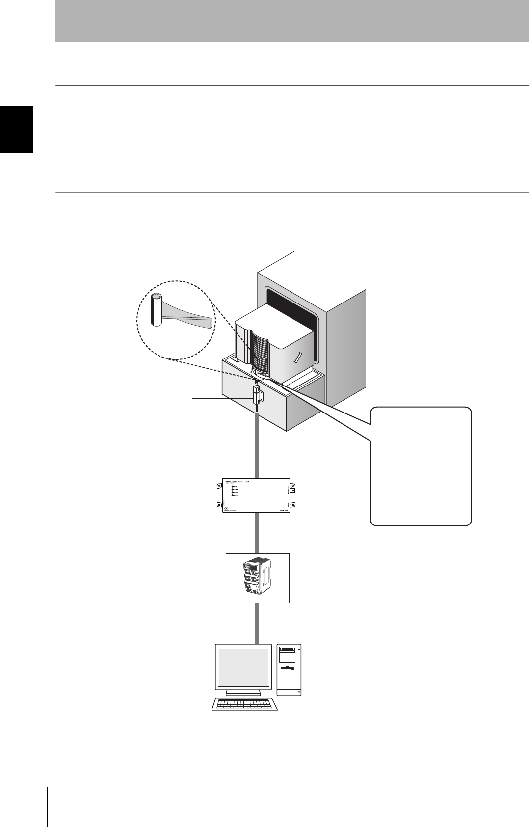
The CIDRW system writes data to, and reads data from, the carrier IDs (ID Tags) mounted on the carriers
(FOUP) in semiconductor manufacturing processes without contacting these ID Tags. CIDRW is the
abbreviation of Carrier ID Reader/Writer and this abbreviation is used throughout this manual.
Reading and writing information such as models, process instructions, lots, and inspection results to and from
ID Tags makes it possible to manage work instruction information from a host device.
Example: Management of information in semiconductor and wafer manufacturing processes
ID Tag
(holder is separate)
CIDRW Head
Reading and writing
information
• Model information
• Process instruction
information
• Completion
information
• Lot information
• Inspection results
Etc.
Host
Amplifier Unit
Ethernet hub

15
CIDRW System
User’s Manual
SECTION 1
Features
SECTION 1
Product Outline
Features
A V640-series CIDRW Head can be connected to a V640-HAM11-ETN or V640-HAM11-L-ETN Amplifier Unit
to read and write ID Tags manufactured by Texas Instruments (TI). Reading and writing is performed
according to commands from the host device.
■V640-HAM11-ETN
The V640-HAM11-ETN Amplifier Unit is equipped with Ethernet. The host device is connected through
a LAN cable and controls the Amplifier Units using TCP/IP. The Amplifier Units provide a Web browser
function that allows communications to be set and status to be managed using simple command com-
munications.
■V640-HAM11-L-ETN
The V640-HAM11-L-ETN Amplifier Unit is equipped with Ethernet and can be connected to a V640-
HS62 CIDRW Head to perform long-distance communications. The functions of the V640-HAM11-L-
ETN Amplifier Unit are the same as those of the V640-HAM11-ETN Amplifier Unit.

16
SECTION 1
System Configuration
CIDRW System
User’s Manual
SECTION 1
Product Outline
System Configuration
V640-HAM11-ETN
V640-HAM11-L-ETN
CIDRW Head
V640-HS61
Amplifier Unit
V640-HAM11-ETN
Ethernet hub
Host device
LAN cable LAN cable
CIDRW Head
V640-HS61
Amplifier Unit
V640-HAM11-ETN
LAN cable
CIDRW Head
V640-HS61
Amplifier Unit
V640-HAM11-ETN
LAN cable
Host device
CIDRW Head
V640-HS62
Amplifier Unit
V640-HAM11-L-ETN
Ethernet hub
LAN cable LAN cable
CIDRW Head
V640-HS62
Amplifier Unit
V640-HAM11-L-ETN
LAN cable
CIDRW Head
V640-HS62
Amplifier Unit
V640-HAM11-L-ETN
LAN cable
17
CIDRW System
User’s Manual
SECTION 1
Component Names and Functions
SECTION 1
Product Outline
Component Names and Functions
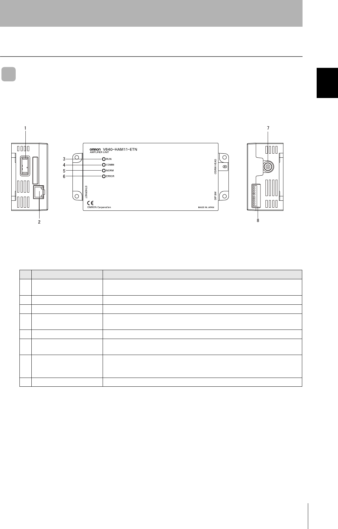
V640-HAM11-ETN and V640-HAM11-L-ETN Amplifier Units
No. Name Function
1 Dedicated power supply con-
nector
Connect to the 24 VDC power supply.
2 Ethernet port Connect to the host device through a LAN cable.
3 RUN indicator (green) Turns ON when the Amplifier Unit is in normal operation.
4 COMM indicator (yellow) Turns ON during communications with the host device or during communications with an
ID Tag.
5 NORM indicator (green) Turns ON when the communications finish with no error.
6 ERROR indicator (red) Turns ON when an error occurs during communications with the host device, or during
communications with an ID Tag.
7 CIDRW Head connection port A CIDRW Head is connected here.
The V640-HS61 CIDRW Head is used with the V640-HAM11-ETN. The V640-HS62
CIDRW Head is used with the V640-HAM11-L-ETN.
8 Setting DIP switches Set the IP address and enable/disable the Test Mode with this DIP switch.
18
SECTION 1
Component Names and Functions
CIDRW System
User’s Manual
SECTION 1
Product Outline
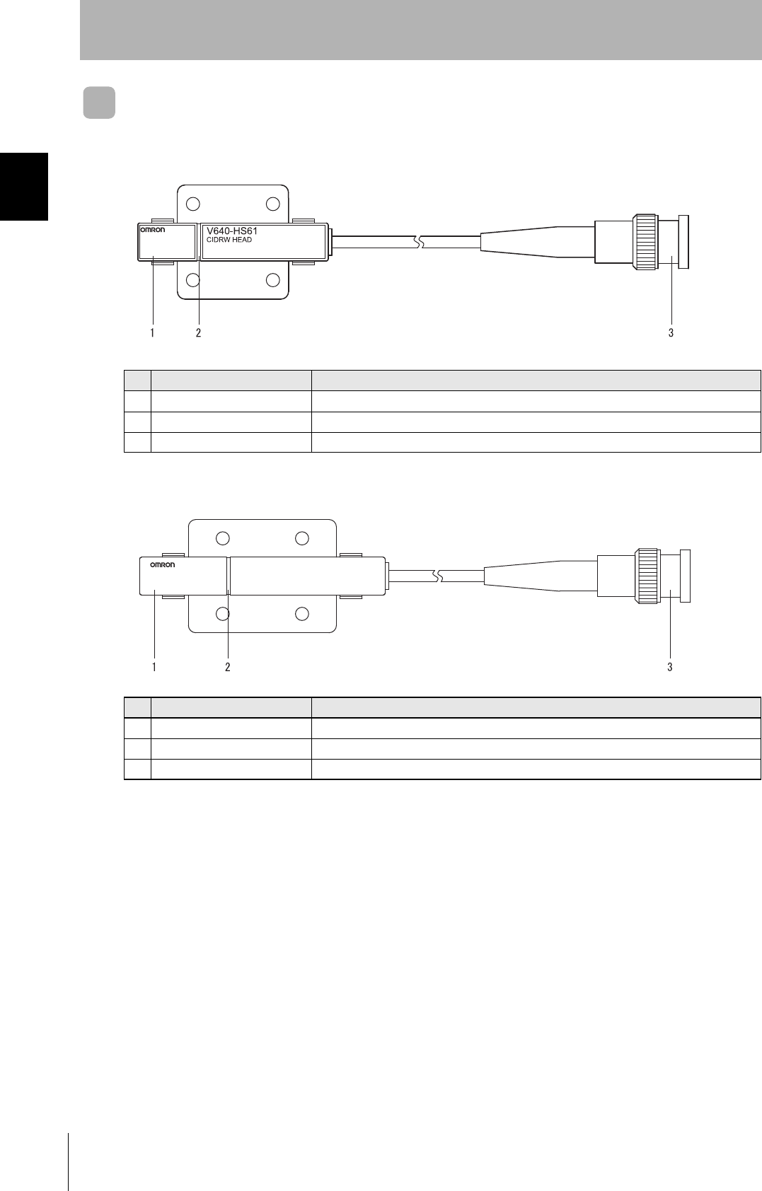
V640-HS61 and V640-HS62 CIDRW Heads
■V640-HS61
■V640-HS62
No. Name Function
1 Antenna Used to communicate with ID Tags.
2 Antenna center This is the center of the communications area.
3 Connector Connect to an Amplifier Unit.
No. Name Function
1 Antenna Used to communicate with ID Tags.
2 Antenna center This is the center of the communications area.
3 Connector Connect to an Amplifier Unit.
V640-HS62
CIDRW HEAD
MADE IN JAPAN
19
CIDRW System
User’s Manual
SECTION 1
Flowchart for Getting Started
SECTION 1
Product Outline
Flowchart for Getting Started
Refer to page 22.
Refer to page 25.
Refer to page 30.
Refer to page 32.
Refer to page 33.
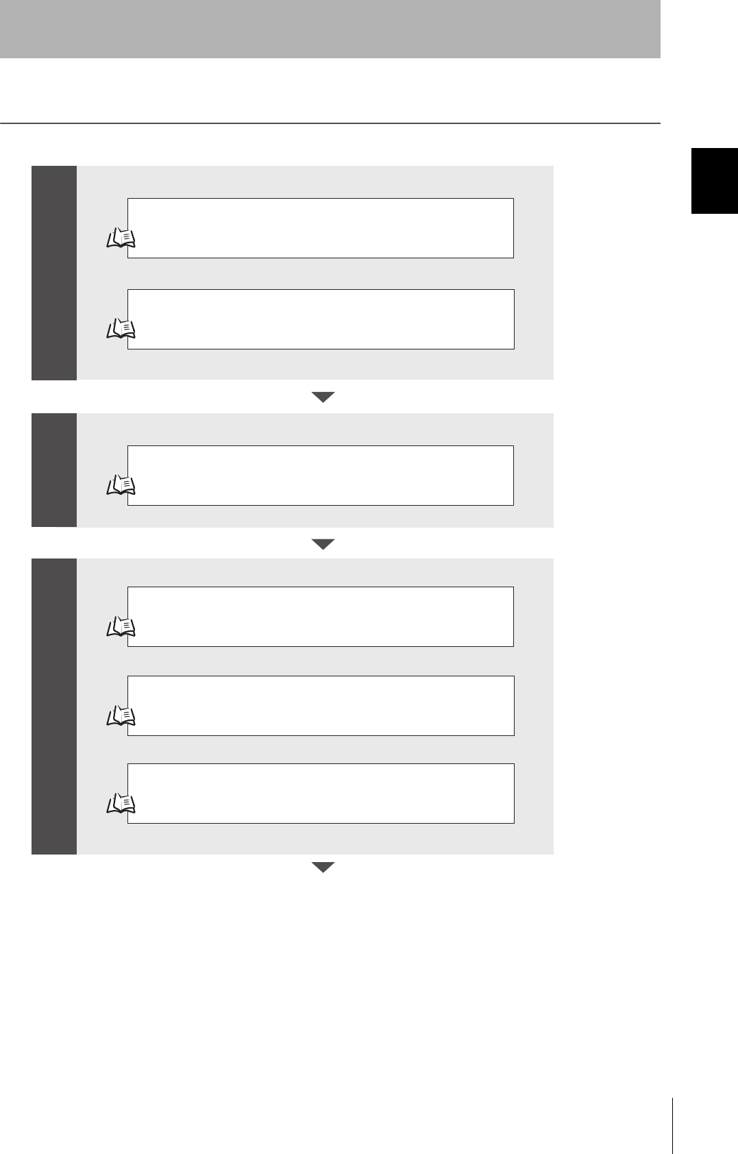
Installation
Connection and Wiring
Setting the Communications Conditions for Amplifier Units
Test for Communications with the Host Device
ID Tag <-> CIDRW System Communications Test
Check the Surrounding Environment
Refer to page 23.
Preparation for
Communications
Trial Operation Installation and Connections
20
SECTION 1
Flowchart for Getting Started
CIDRW System
User’s Manual
SECTION 1
Product Outline
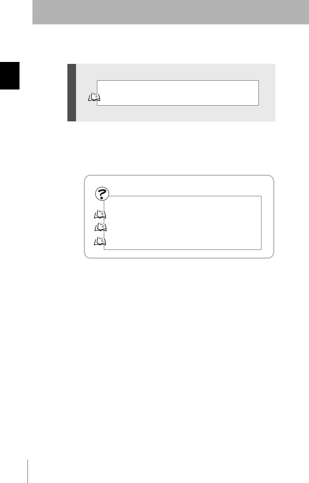
Refer to page 36.
Refer to page 70. List of Error Messages
Refer to page 70. Amplifier Unit Indicators
Refer to page 71. Operation Check Flowchart
Communications Test with Actual Commands
Troubleshooting
When you Encounter a Problem...
Communications

SECTION 2
Installation and Connections/Wiring
21
CIDRW System
User’s Manual
SECTION 2
Installation and Connections/Wiring
Installation 22
Amplifier Unit 22
CIDRW Head 23
Connections and Wiring 25
Amplifier Unit 25
22
SECTION 2
Installation
CIDRW System
User’s Manual
SECTION 2
Installation and Connections/Wiring
Installation
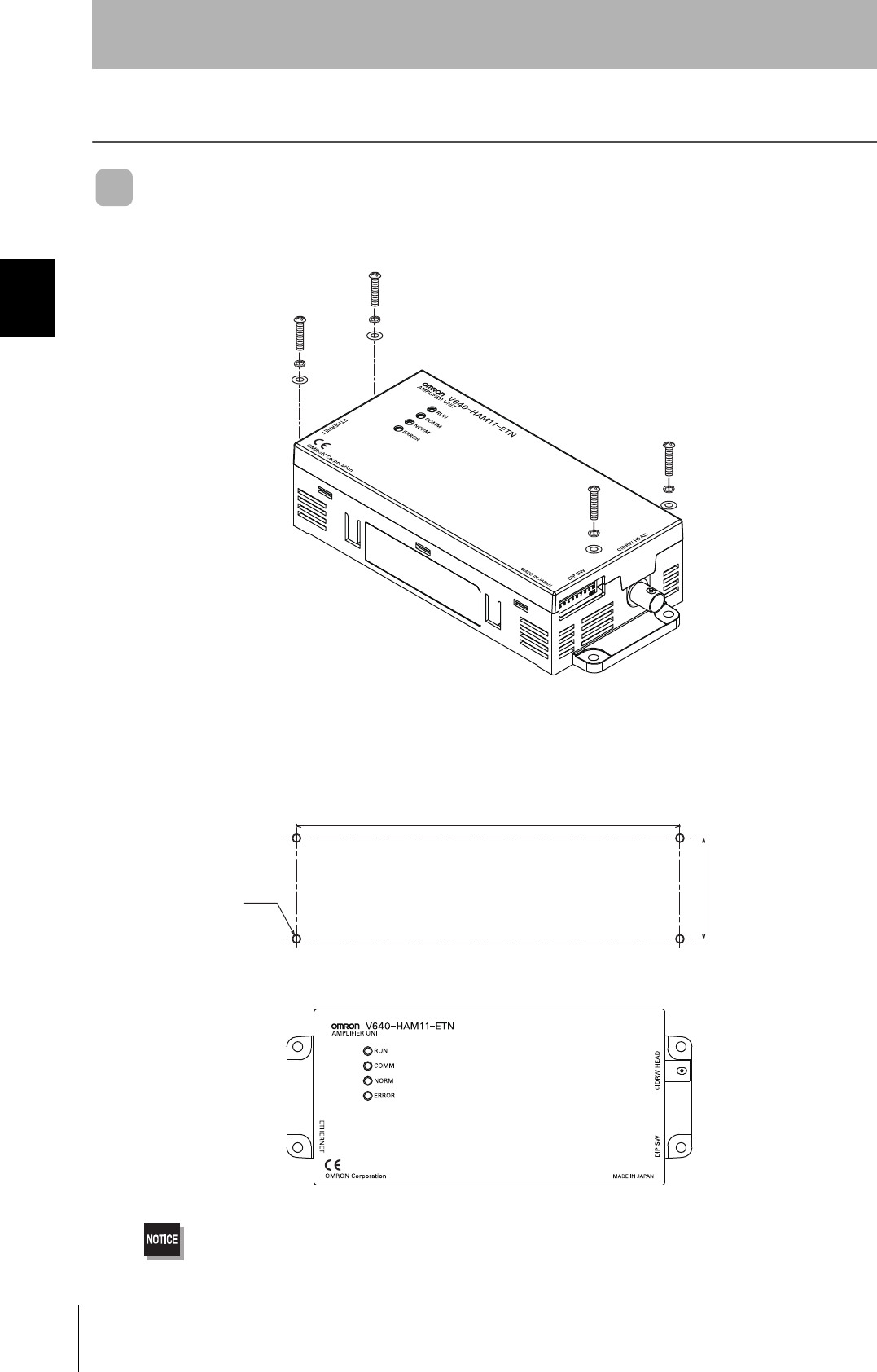
Amplifier Unit
Use spring washers and flat washers with the four M4 screws when mounting the Amplifier Unit.
Tighten the M4 screws with a torque not exceeding 1.2 N·m.
175±0.5
46±0.5
4-M4
Mounting dimensions
(Unit: mm)
23
CIDRW System
User’s Manual
SECTION 2
Installation
SECTION 2
Installation and Connections/Wiring
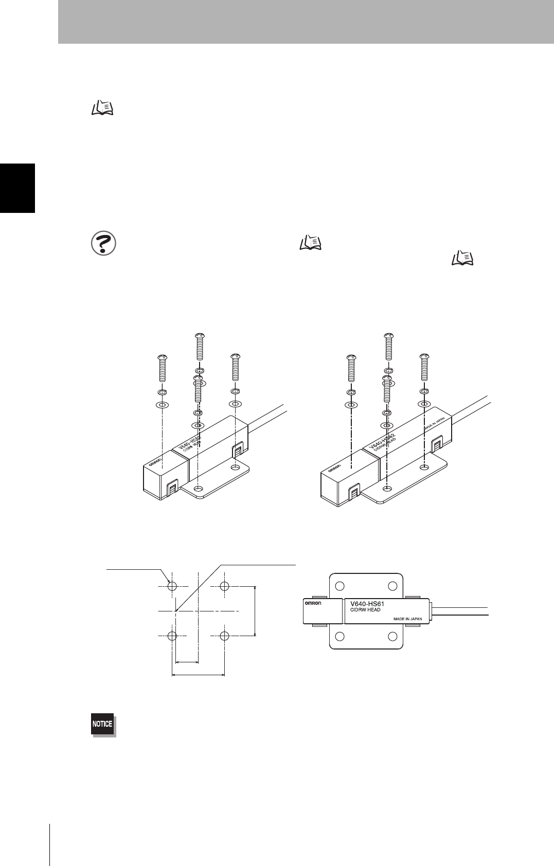
CIDRW Head
The area for communications with ID Tags varies substantially according to the installation orientations
and the background conditions (metals, noise, etc.). Check the communications area before deciding
the installation position.
For details on actual communications distances, see Characteristic Data depending on Conditions of
Use in Appendix.
Refer to page 81.
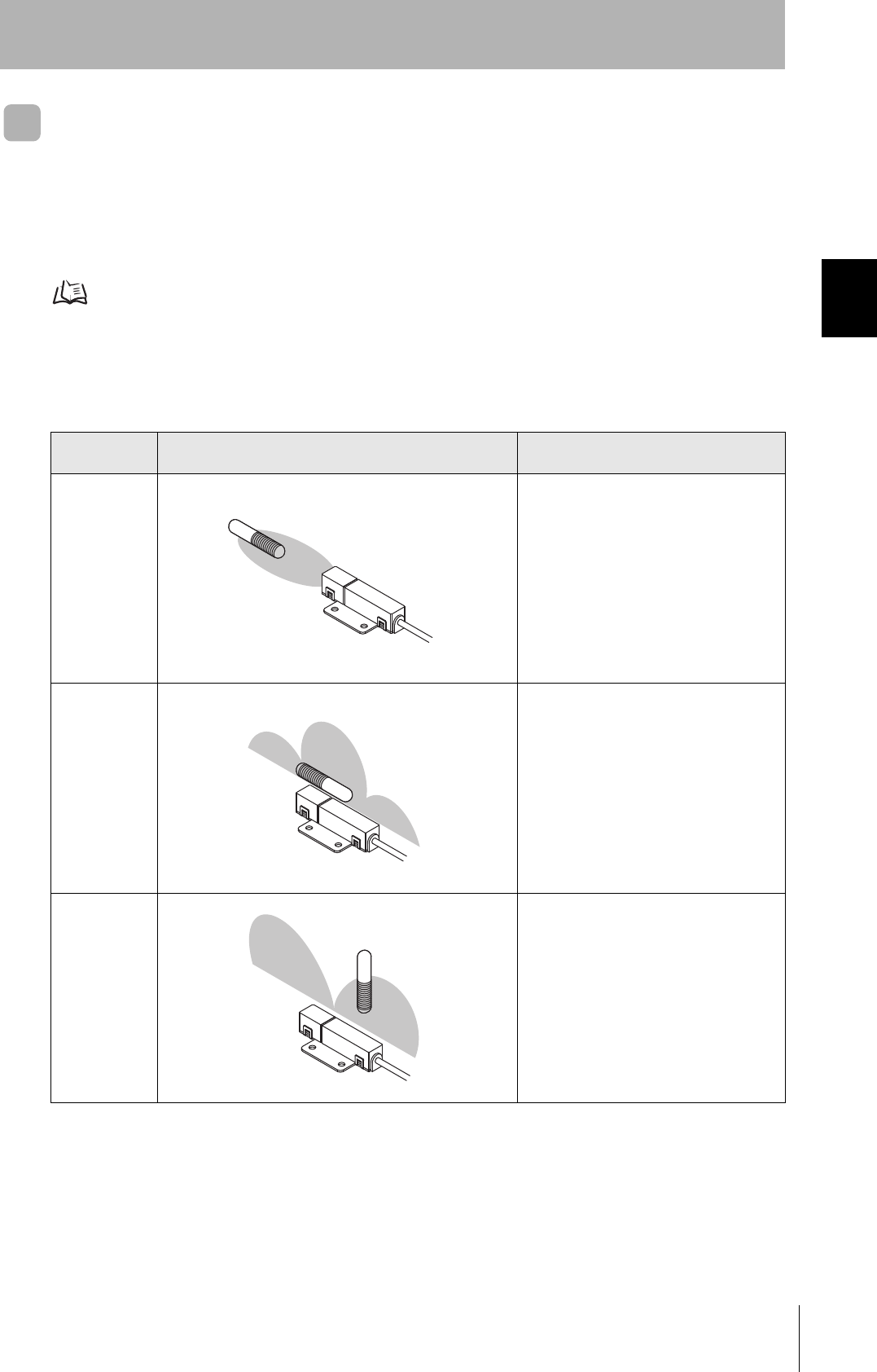
■Positional Relationship between the CIDRW Head and the ID Tag
The communications area differs according to the positional relationship during communications.
■Data Reading and Writing
The communications distances for reading and writing are not the same; the distance is shorter for
writing. Therefore, when data is to be both read and written, take the distance for writing as the refer-
ence distance when installing the CIDRW Head and the ID Tag.
Mounting
orientation Communications area (purely illustrative) Explanation
Coaxial The maximum communications area is
obtained when the center lines of the CIDRW
Head and the ID Tag coincide.
Parallel The maximum communications area is
obtained when the center point of the
antenna on the CIDRW Controller is aligned
with the center line of the ID Tag.
Vertical When the center point of the antenna on the
CIDRW Head is aligned with the center line
of the ID Tag, the communications area is
substantially reduced.
24
SECTION 2
Installation
CIDRW System
User’s Manual
SECTION 2
Installation and Connections/Wiring
■Influence of Background Metal on ID Tag
Metals in the vicinity of the communications area will affect the range, making it smaller.
Refer to page 106.
■Influence of Noise
This CIDRW system uses a frequency of 134 kHz for communications with ID Tags. Equipment such
as switching power supplies, inverters, servomotors, or monitors in the surrounding area will adversely
affect communications, restricting the communications area.
The noise levels in the vicinity of the CIDRW Head can be determined with the environmental NOISE MEASUREMENT
command (applies only when SECS is not used) . Refer to page 43.
For details on the relationship between noise and communications distance, see Appendix . Refer to page 110.
■Mounting
Use spring washers and flat washers with the four M3 screws when mounting a CIDRW Head.
Tighten the M3 screws with a torque not exceeding 0.6 N·m.
4-M3 OR φ3.5
Mounting dimensions (Unit: mm)
Antenna center
21±0.2
20±0.2

25
CIDRW System
User’s Manual
SECTION 2
Connections and Wiring
SECTION 2
Installation and Connections/Wiring
Connections and Wiring
Amplifier Unit
■Connector for Connecting a CIDRW Head
1. Align the pin on the connector with the
channel in the cable connector and
insert the cable connector.
Hold the fixed part of the connector while making
this insertion.
2. After inserting the connector fully
home, turn the fixed part clockwise to
lock it.
26
SECTION 2
Connections and Wiring
CIDRW System
User’s Manual
SECTION 2
Installation and Connections/Wiring
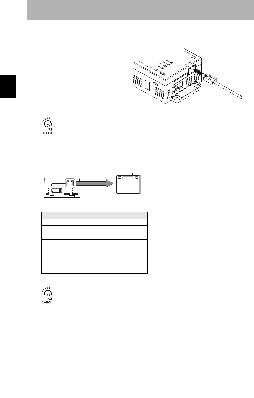
■Ethernet Connector
1. Hold the connector on the cable and
insert it into the Ethernet connector on
the Amplifier Unit.
Press in the connector until it locks in place when connecting the Amplifier Unit to Ethernet, including when connecting
it to a hub.
• Connector
The Amplifier Unit provides an auto-MDIX function that enables communications by connecting either
a cross LAN cable or straight LAN cable.
The shape and dimensions of plugs and jacks for Ethernet connectors are specified in ISO/IEC 8877:1992 (JIS X
5110:1996) To prevent faulty connections for connectors, the jack on the Amplifier Unit is designed so that non-standard
plugs cannot be connected. If a commercially available plug cannot be connected, it may be non-standard.
Pin No. Signal name Description I/O
1 TX_D+ Send data + Output
2TX_D−Send data −Output
3 RX_D+ Receive data + Input
4−−−
5−−−
6RX_D−Receive data −Input
7−−−
8−−−
18
27
CIDRW System
User’s Manual
SECTION 2
Connections and Wiring
SECTION 2
Installation and Connections/Wiring
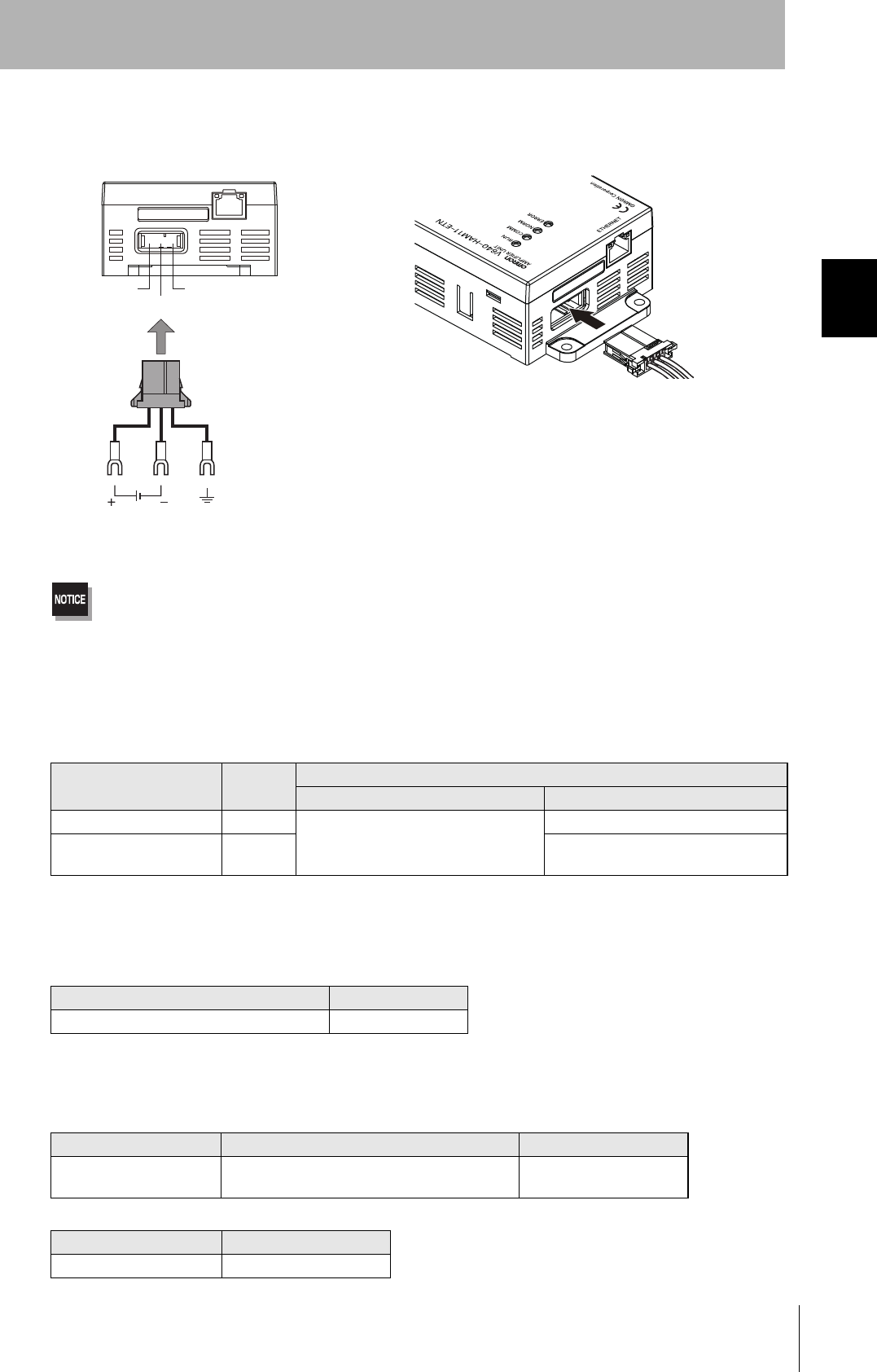
■Power Supply and Grounding Wires
Connect the power supply and grounding wires to the dedicated power supply connector.
•The grounding wire should be connected to a ground exclusive to the Amplifier Unit. If the grounding wire is shared
with another unit, or connected to a beam in a building, there may be adverse effects.
•Make the grounding point as close as possible and the length of the grounding wire used as short as possible.
•When using the Amplifier Unit in Europe, the connecting cable between the Amplifier Unit and the DC power supply
must be 3 m or less.
• Dedicated Power Supply Connector and RS-485 Port Connector
Obtain the V640-A91 Set (accessory, sold separately).
• Dedicated Power Supply Cable
Use an AWG20 to AWG24 cable.
Use a dedicated tool for crimping the cable to the connector pins.
• Power Supply
Use a power supply that satisfies the following conditions.
Contents of V640-A91 Set
Name Quantity When procured individually
Manufacturer Model
Power supply connector One Tyco Electronics 1-178288-3
Pins for power supply con-
nector
Three 175217-3
Recommended Crimping Tool
Manufacturer Model
Tyco Electronics 919601-1
Condition
Power supply voltage Output current Safety standard
24 VDC +10%, -15% V640-HAM11-ENT: 300 mA DC min.
V640-HAM11-L-ENT: 600 mA DC min.
UL Class 2
Recommended Product
Manufacturer Model
OMRON S82K-03024
24 V+ 24 V-
GR
24 VDC Ground to 100 Ω or less
Connector

28
SECTION 2
Connections and Wiring
CIDRW System
User’s Manual
SECTION 2
Installation and Connections/Wiring
MEMO

SECTION 3
Preparing for Communications
29
CIDRW System
User’s Manual
SECTION 3
Preparing for Communications
Setting the Communications Conditions for Amplifier Units 30
Communications Test 32
30
SECTION 3
Setting the Communications Conditions for Amplifier Units
CIDRW System
User’s Manual
SECTION 3
Preparing for Communications
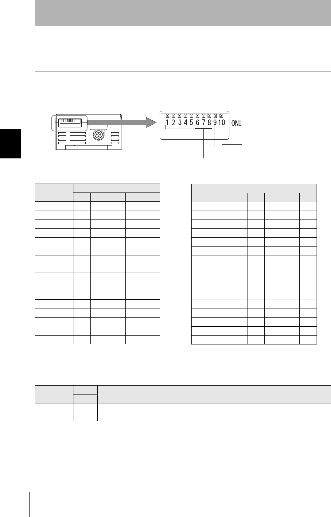
Setting the Communications Conditions for Amplifier
Units
Set the communications conditions using the DIP switches on the side face of the Amplifier Unit.
After changing the DIP switch settings, restart the system. The new settings will not become effective until the
system is restarted.
Test Mode
Test Mode DIP-SW Description
9
Disabled ON Set the Test Mode and then restart the Amplifier Unit to make the setting effective.
Enabled OFF
IP address
Always OFF
(Not used in this CIDRW system)
Test Mode Always OFF
(Not used in this CIDRW system)
IP Address
IP address DIP switch
1 2 3 4 5
Setting in ROM OFF OFF OFF OFF OFF
192.168.1.1 ON OFF OFF OFF OFF
192.168.1.2 OFF ON OFF OFF OFF
192.168.1.3 ON ON OFF OFF OFF
192.168.1.4 OFF OFF ON OFF OFF
192.168.1.5 ON OFF ON OFF OFF
192.168.1.6 OFF ON ON OFF OFF
192.168.1.7 ON ON ON OFF OFF
192.168.1.8 OFF OFF OFF ON OFF
192.168.1.9 ON OFF OFF ON OFF
192.168.1.10 OFF ON OFF ON OFF
192.168.1.11 ON ON OFF ON OFF
192.168.1.12 OFF OFF ON ON OFF
192.168.1.13 ON OFF ON ON OFF
192.168.1.14 OFF ON ON ON OFF
192.168.1.15 ON ON ON ON OFF
IP address DIP switch
1 2 3 4 5
192.168.1.16 OFF OFF OFF OFF ON
192.168.1.17 ON OFF OFF OFF ON
192.168.1.18 OFF ON OFF OFF ON
192.168.1.19 ON ON OFF OFF ON
192.168.1.20 OFF OFF ON OFF ON
192.168.1.21 ON OFF ON OFF ON
192.168.1.22 OFF ON ON OFF ON
192.168.1.23 ON ON ON OFF ON
192.168.1.24 OFF OFF OFF ON ON
192.168.1.25 ON OFF OFF ON ON
192.168.1.26 OFF ON OFF ON ON
192.168.1.27 ON ON OFF ON ON
192.168.1.28 OFF OFF ON ON ON
192.168.1.29 ON OFF ON ON ON
192.168.1.30 OFF ON ON ON ON
192.168.1.31 ON ON ON ON ON
If the IP address is set on the DIP switch, it will be in the form 192.168.1.@@@. The subnet mask is always 255.255.255.0
The IP address of the Amplifier Unit can be either set on this DIP switch or the desired IP address can be set in ROM. If pins 1 to 5 on the
DIP switch are all turned OFF, the IP address that is set in ROM will be used.

31
CIDRW System
User’s Manual
SECTION 3
Setting the Communications Conditions for Amplifier Units
SECTION 3
Preparing for Communications
Test Mode
Test Mode can be used to check communications between the ID Tags and Amplifier Units without
connecting a host device. Communications with ID Tags are automatically performed every second
and the communications results are displayed on the OPERATING indicator.
Refer to V640-HAM11-ETN and V640-HAM11-L-ETN Amplifier Units for information on the OPERATING indicator for communi-
cations results.
Refer to page 17.
Always connect the CIDRW Head before operating the Amplifier Unit in Test Mode. If Test Mode is used without connecting a
CIDRW Head, the ERROR inductor will light and Amplifier Unit operation will stop.
Commands from the host device are not accepted during operation in Test Mode. To end Test Mode, turn OFF the Test Mode pin
on the DIP switch and restart the Amplifier Unit.

32
SECTION 3
Communications Test
CIDRW System
User’s Manual
SECTION 3
Preparing for Communications
Communications Test
Communications Test with the Host Device
A communications test is performed to confirm that the host device and Amplifier Unit are connected
correctly.
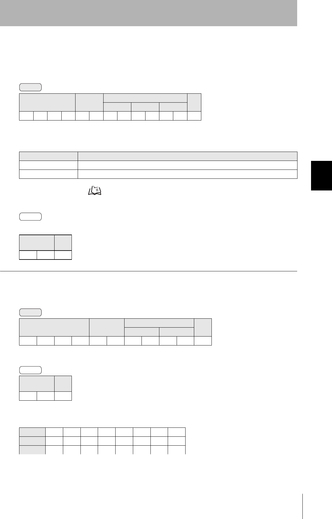
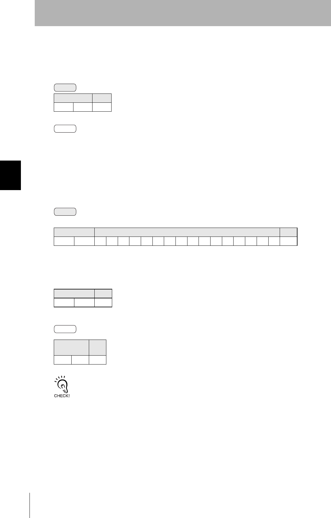
A test is preformed for the Amplifier Unit using the data 12345678.
Command code Test data CR
Data 1 Data 2 Data 3 Data 4
1 0 123456780Dh
Response
code
Test data CR
Data 1 Data 2 Data 3 Data 4
00123456780Dh
Host Amplifier Unit
Command
Response
33
CIDRW System
User’s Manual
SECTION 3
Communications Test
SECTION 3
Preparing for Communications
Communications Test between ID Tags and CIDRW System
Send a command from the host device and check that normal communications with the ID Tag is pos-
sible. Place an ID Tag in the communications area of the CIDRW Head connected to the Amplifier Unit
for which communications is to be tested.
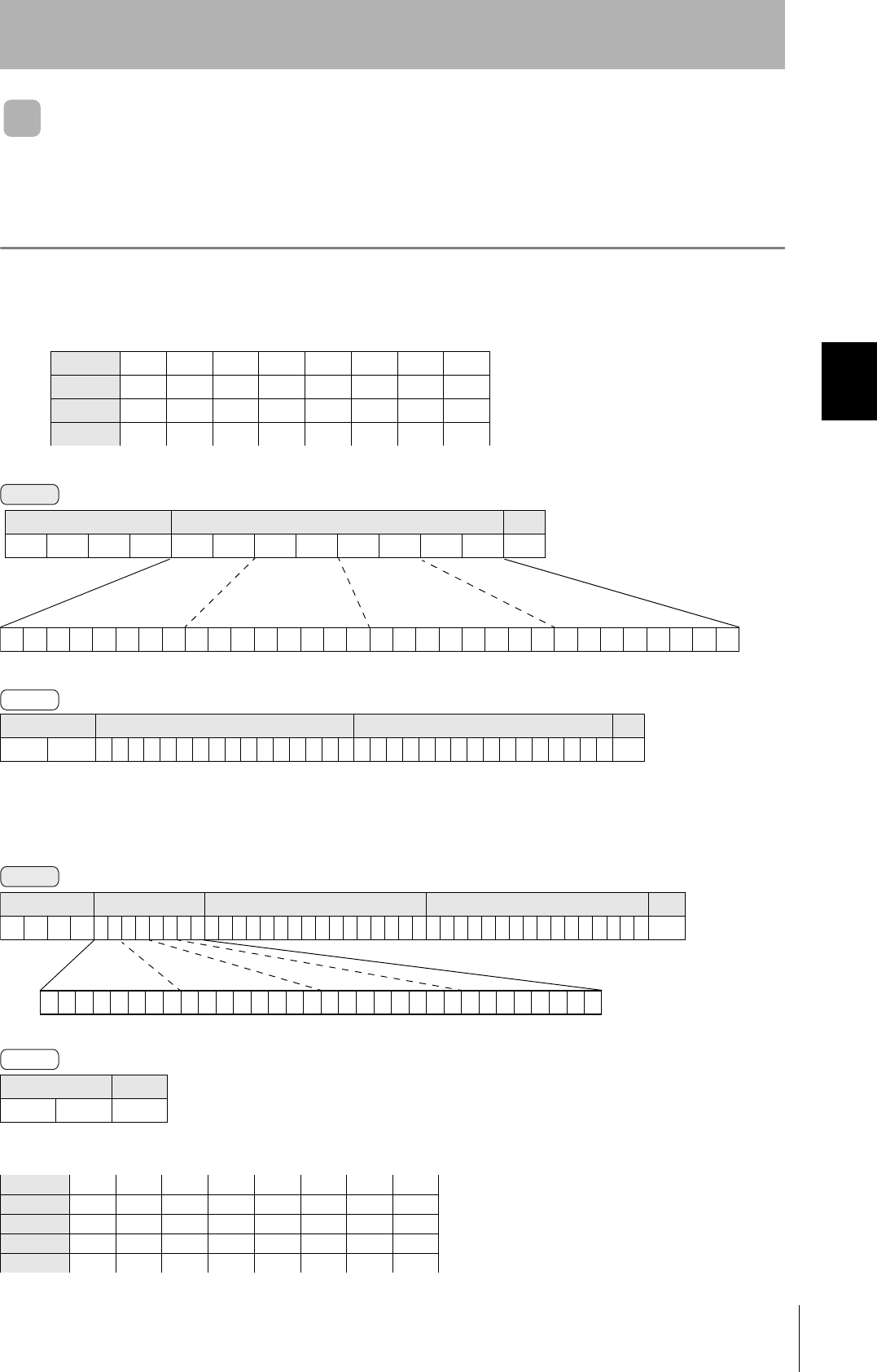
• READ
The data is read from pages 1 and 3 of the Amplifier Unit.
•WRITE
The data is written to pages 8 and 10 of the Amplifier Unit.
If the command ends normally, the contents of the ID Tag will be as follows:
ID Tag contents
Page 1 12h 34h 56h 78h 90h 12h 34h 56h
Page 2
Page 3 11h 22h 33h 44h 55h 66h 77h 88h
Page 4
Response code Page 1 Page 3 CR
0 0 123456789012345611223344556677880Dh
Response code CR
000Dh
Page 8 11h 22h 33h 44h 55h 66h 77h 88h
Page 9
Page 10 01h 23h 45h 67h 89h ABh CDh EFh
Command
00000000000000000000000000010100
Binary notation
Command code Page designation CR
0100000000140Dh
Response
Command
00000000000000000000101000000000
Command code Page designation Data of page 8 Data of page 10 CR
0 2 0 0 00000A0011223344556677880123456789ABCDEF 0Dh
Binary
notation
Response

34
SECTION 3
Communications Test
CIDRW System
User’s Manual
SECTION 3
Preparing for Communications
MEMO

SECTION 4
Reading from/Writing to ID Tags
35
CIDRW System
User’s Manual
SECTION 4
Reading from/Writing to ID Tags
Command/Response Format 36
READ 37
WRITE 38
SAME WRITE 40
BYTE WRITE 41
TEST 42
NAK 43
GET PARAMETER 43
GET LAST COMMAND 48
GET COMMUNICATIONS HISTORY 48
CLEAR COMMUNICATIONS HISTORY 49
NOISE MEASUREMENT 49
RESET 50
SET WEB PASSWORD 50
SET NETWORK 51

36
SECTION 4
Command/Response Format
CIDRW System
User’s Manual
SECTION 4
Reading from/Writing to ID Tags
Command/Response Format
Command
Command
Command code Parameter CR
1 ⋅ ⋅ ⋅ n
0Dh
Response
Response
code
Parameter CR
1 ⋅ ⋅ ⋅ n
0Dh
Command Code List
Name Value Function See
READ 0100 When this command is received, the system communicates with the ID Tag, and
reads the specified page(s) of data. Any pages up to a maximum of 16 can be
selected.
p.37
WRITE 0200 When this command is received, the system communicates with the ID Tag, and
writes the specified page(s) of data. Any pages up to a maximum of 16 can be
selected.
p.38
SAME WRITE 0300 When this command is received, the system communicates with the ID Tag, and
writes the same data in page units to the specified pages. Up to 17 pages, which is
the maximum number of pages for an ID Tag, can be specified.
p.40
BYTE WRITE 0400 When this command is received the system communicates with the ID Tag, and
writes data to the area specified by a first address and number of bytes. A maximum
of 128 bytes can be specified.
p.41
TEST 10 Sends received data to the host device. p.42
NAK 12 Sends the response made immediately before again. p.43
GET PARAMETER 14 Gets the model number, MAC address, or another parameter. p.43
GET LAST COM-
MAND
15 Gets the command code of the last command that was executed. p.48
GET COMMUNICA-
TIONS HISTORY
16 Gets the history of communications from when the power was turned ON (total num-
ber of communications, total successful communications, and total number of failed
communications).
p.48
CLEAR COMMUNI-
CATIONS HISTORY
17 Clears the communications history. p.49
NOISE MEASURE-
MENT
40 Measures the noise in the vicinity of the CIDRW Head. p.49
RESET 7F Resets the Amplifier Unit. p.50
SET WEB PASS-
WORD
A2 Sets the Web password. p.50
SET NETWORK A3 Sets the network. p.51
37
CIDRW System
User’s Manual
SECTION 4
Command/Response Format
SECTION 4
Reading from/Writing to ID Tags
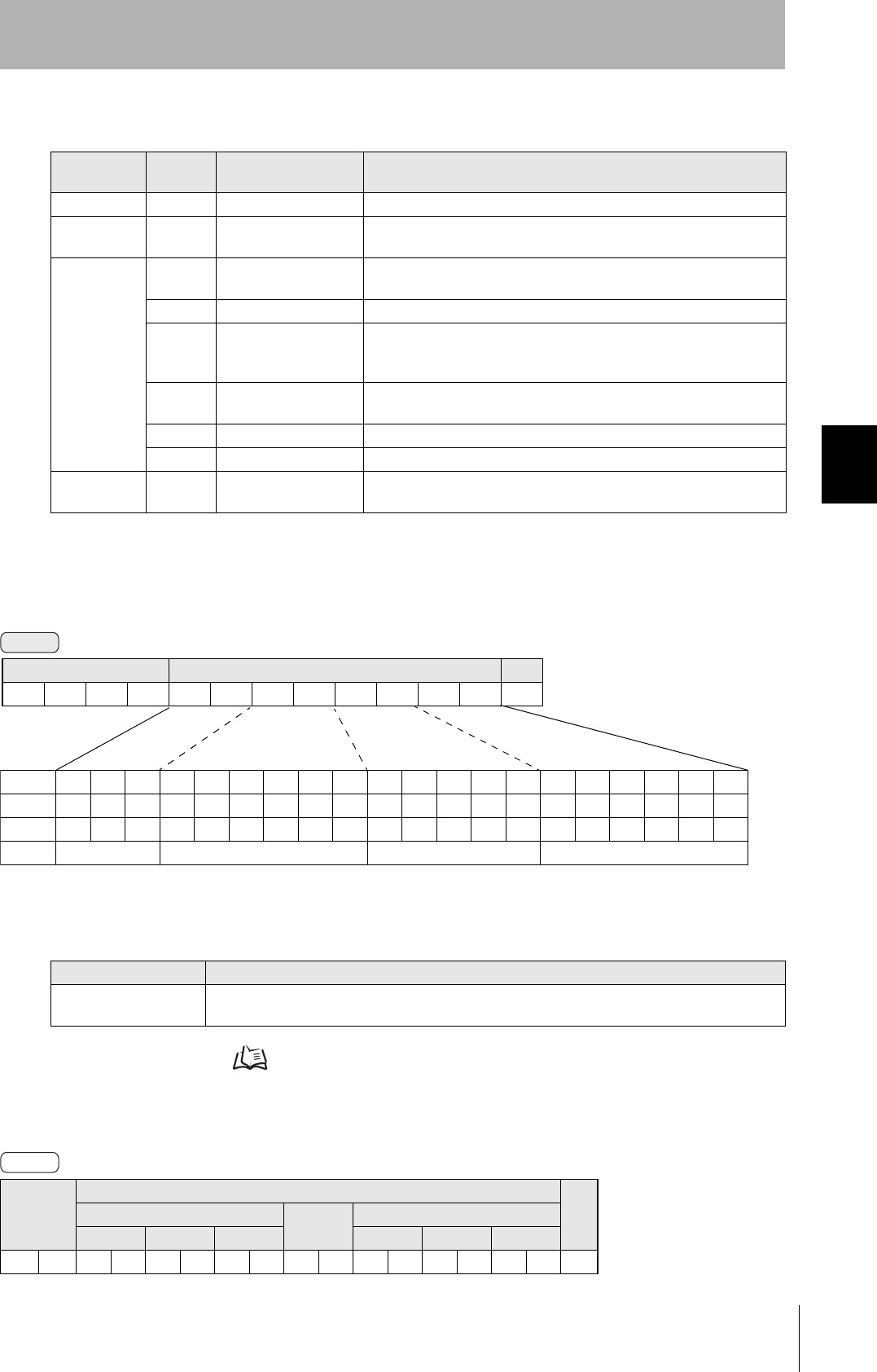
■READ
Reads any pages of data from the ID Tag. The maximum number of pages that can be read at one time
is 16.
ID Tag Memory Maps Refer to page 111.
The response code (when normal: 00) and the data in the specified pages are returned in ascending order of
page numbers.
Response Code List
Type Response
code Name Description
Normal end 00 Normal end Command execution is completed normally.
Host commu-
nications error
14 Format error There is a mistake in the command format. (For example, the command
code is undefined, or the page or address specification is inappropriate.)
Communica-
tions error
70 Communications error Noise or another hindrance occurs during communications with an ID
Tag, and communications cannot be completed normally.
71 Verification error Correct data cannot be written to an ID Tag.
72 No Tag error Either there is no ID Tag in front of the CIDRW Head, or the CIDRW
Head is unable to detect the ID Tag due to environmental factors (e.g.,
noise).
7B Outside write area error A write operation was not completed normally because the ID Tag was
in an area in which the ID Tag could be read but not written.
7E ID system error (1) The ID Tag is in a status where it cannot execute command processing.
7F ID system error (2) An inapplicable ID Tag has been used.
CPU hardware
error
9A Hardware error in CPU An error occurred when writing to EEPROM.
Parameter Description
Parameter Description
Page designation Pages are specified by setting the bits corresponding to pages that are to be read to 1 and setting
the other bits to 0, then converting the result to a hexadecimal character string.
Response
code
Read data
CRPage n
⋅ ⋅ ⋅
Page m (n<m)
Data 1 ⋅ ⋅ ⋅ Data 8 Data 1 ⋅ ⋅ ⋅ Data 8
00 0Dh
Command
Bit 7-07-321076-1076-210
Page Sys - Sys Sys - Sys 17 16 15 14 13 - 8 7 6 5 - 1 Sys Sys
Designation 0* 0* 0* 0* 0* 0/1 0/1 0/1 0/1 0/1 ••• 0/1 0/1 0/1 0/1 ••• 0/1 0* 0*
Value 00 00 to 07 00 to FF 00 to FC
* Always specify 0. If you specify 1 an error (Response code: 14) will occur.
Command code Page designation (8 characters) CR
0100 0Dh
Response
38
SECTION 4
Command/Response Format
CIDRW System
User’s Manual
SECTION 4
Reading from/Writing to ID Tags
Example: Reading Data from Pages 1 and 3 of the Amplifier Unit.
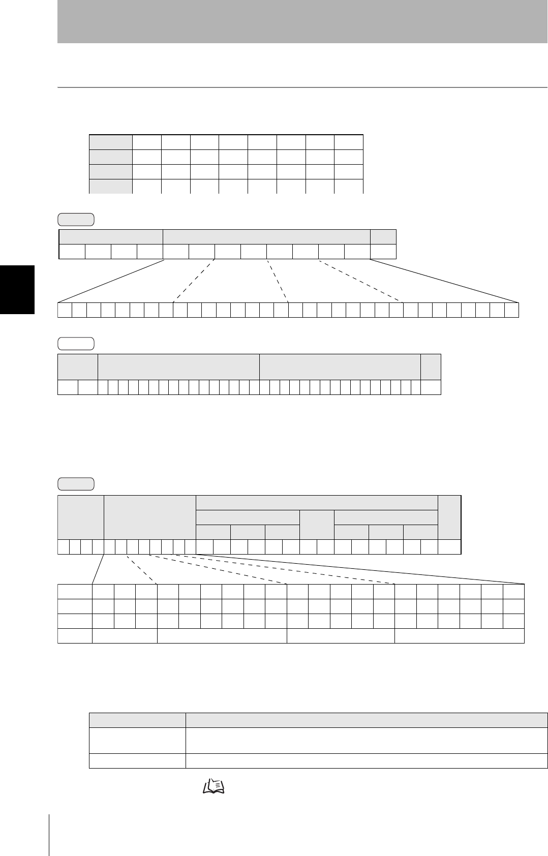
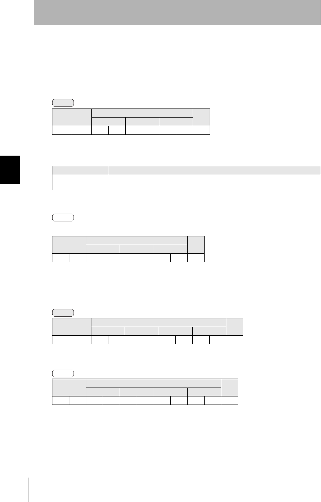
■WRITE
Data is written in page units to the ID Tag. Any page(s) can be specified. It is possible to write to a max-
imum of 16 pages at one time.
ID Tag Memory Maps Refer to page 111.
Data Content of the ID Tag
Page 1 12h 34h 56h 78h 90h 12h 34h 56h
Page 2
Page 3 11h 22h 33h 44h 55h 66h 77h 88h
Page 4
Response
code Page 1 Page 3 CR
0 0 123456789012345611223344556677880Dh
Parameter Description
Parameter Description
Page designation Pages are specified by setting the bits corresponding to pages that are to be read to 1 and setting
the other bits to 0, then converting the result to a hexadecimal character string.
Write data The data to be written to the specified pages is specified in ascending order of page numbers.
Command
00000000000000000000000000010100
Binary notation
Command code Page designation CR
0100000000140Dh
Response
Command
Bit 7-07-321076-1076-210
Page Sys - Sys Sys - Sys 17 16 15 14 13 - 8 7 6 5 - 1 Sys Sys
Designation 0* 0* 0* 0* 0* 0/1 0/1 0/1 0/1 0/1 ••• 0/1 0/1 0/1 0/1 ••• 0/1 0* 0*
Value 00 00 to 07 00 to FF 00 to FC
* Always specify 0. If you specify 1 an error (Response code: 14) will occur.
Command
code
Page designation
(8 characters)
Write data
CRPage n
⋅ ⋅ ⋅
Page m (n<m)
Data 1 ⋅ ⋅ ⋅ Data 8 Data 1 ⋅ ⋅ ⋅ Data 8
0200 0DH

39
CIDRW System
User’s Manual
SECTION 4
Command/Response Format
SECTION 4
Reading from/Writing to ID Tags
The response code (when normal: 00) is returned.
Example: Writing Data to Pages 8 and 10 of the Amplifier Unit
The ID Tag status on normal completion is as shown below.
Response
code CR
000Dh
Response
code CR
000Dh
Page 8 11h 22h 33h 44h 55h 66h 77h 88h
Page 9
Page 10 01h 23h 45h 67h 89h ABh CDh EFh
Response
Command
00000000000000000000101000000000
Command
code
Page designation Data of page 8 Data of page 10 CR
0 2 0 000000A0011223344556677880123456789ABCDEF 0Dh
Binary
notation
Response
40
SECTION 4
Command/Response Format
CIDRW System
User’s Manual
SECTION 4
Reading from/Writing to ID Tags
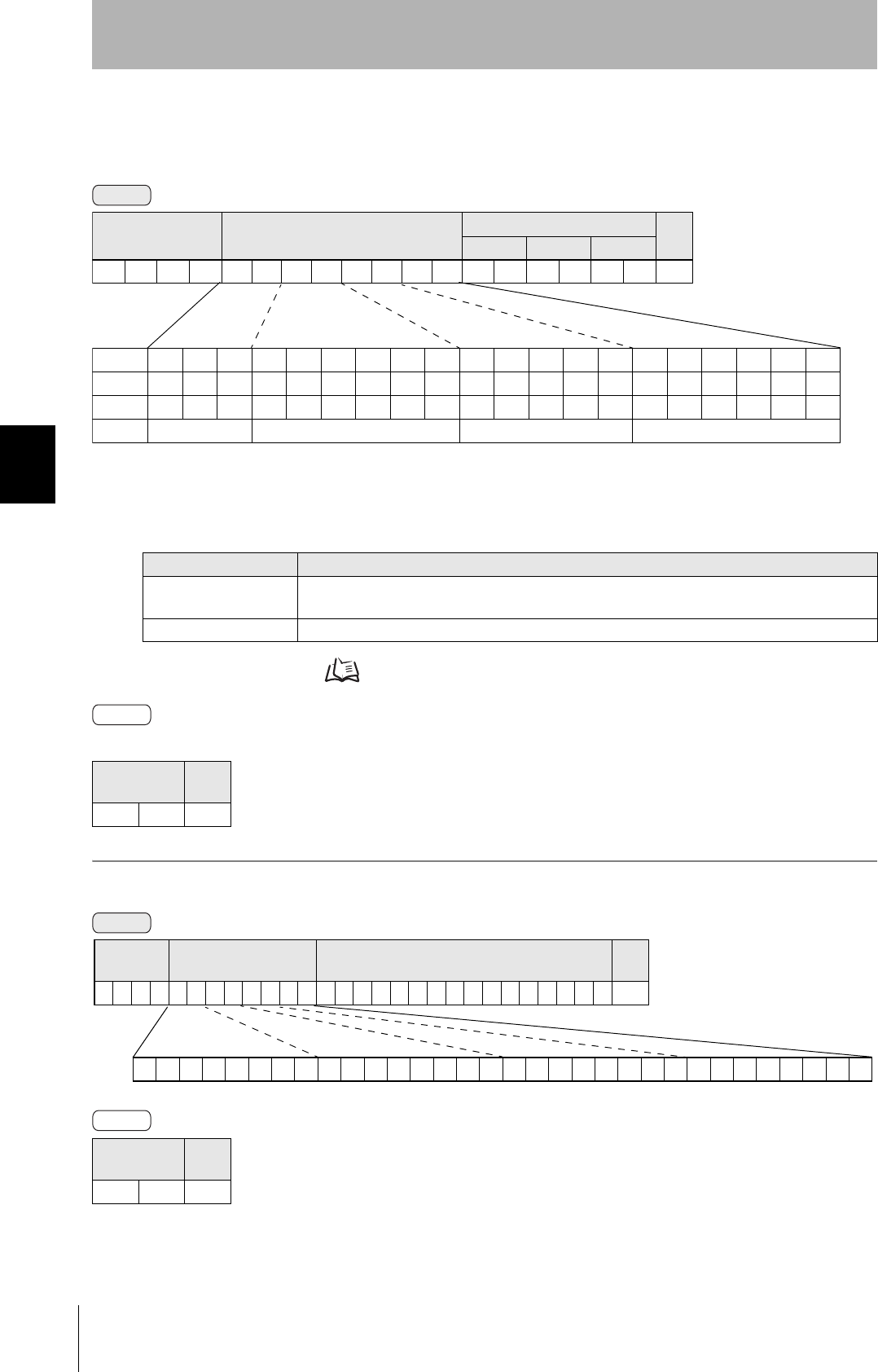
■SAME WRITE
This command writes the same data to multiple pages of an ID Tag. Any page(s) can be specified.
ID Tag Memory Maps Refer to page 111.
The response code (when normal: 00) is returned.
Example: Clearing All Data on Pages 1 and 17 of the Amplifier Unit to 0
Parameter Description
Parameter Description
Page designation Pages are specified by setting the bits corresponding to pages that are to be read to 1 and setting
the other bits to 0, then converting the result to a hexadecimal character string.
Write data Specify the write data.
Response
code CR
000Dh
Response
code CR
000Dh
Command
Command code Page designation (8 characters) Write data CR
Data 1 ⋅ ⋅ ⋅ Data 8
0300 0DH
Bit 7-07-321076-1076-210
Page Sys - Sys Sys - Sys 17 16 15 14 13 - 8 7 6 5 - 1 Sys Sys
Designation 0* 0* 0* 0* 0* 0/1 0/1 0/1 0/1 0/1 ••• 0/1 0/1 0/1 0/1 ••• 0/1 0* 0*
Value 00 00 to 07 00 to FF 00 to FC
* Always specify 0. If you specify 1 an error (Response code: 14) will occur.
Response
Command
00000000000001111111111111111100
Binary
notation
Command
code Page designation Write data CR
03000007FFFC00000000000000000Dh
Response
41
CIDRW System
User’s Manual
SECTION 4
Command/Response Format
SECTION 4
Reading from/Writing to ID Tags
■BYTE WRITE
This command writes data to any specified number of bytes starting from the address specified in the
ID Tag. The maximum number of bytes that can be written at one time is 128.
* Data number n = number of bytes written to (2-character units)
ID Tag Memory Maps Refer to page 111.
The response code (when normal: 00) is returned.
Example: Writing Two Bytes of Data to Address 05h of the Amplifier Unit
The ID Tag status on normal completion is as shown below.
Command code First
address
Write data CR
Data 1 ••• Data n
0400 0Dh
Parameter Description
Parameter Description
First address Addresses can be specified in the range 00h to 87h.
Write data Up to 128 bytes of write data, starting from the specified address, can be specified.
Response
code CR
000Dh
Command code First address Write data CR
Data 1 Data 2
04000512340Dh
Response
code CR
000Dh
Page 1 12h 34h
Page 2
Command
Response
Command
Response
42
SECTION 4
Command/Response Format
CIDRW System
User’s Manual
SECTION 4
Reading from/Writing to ID Tags
■TEST
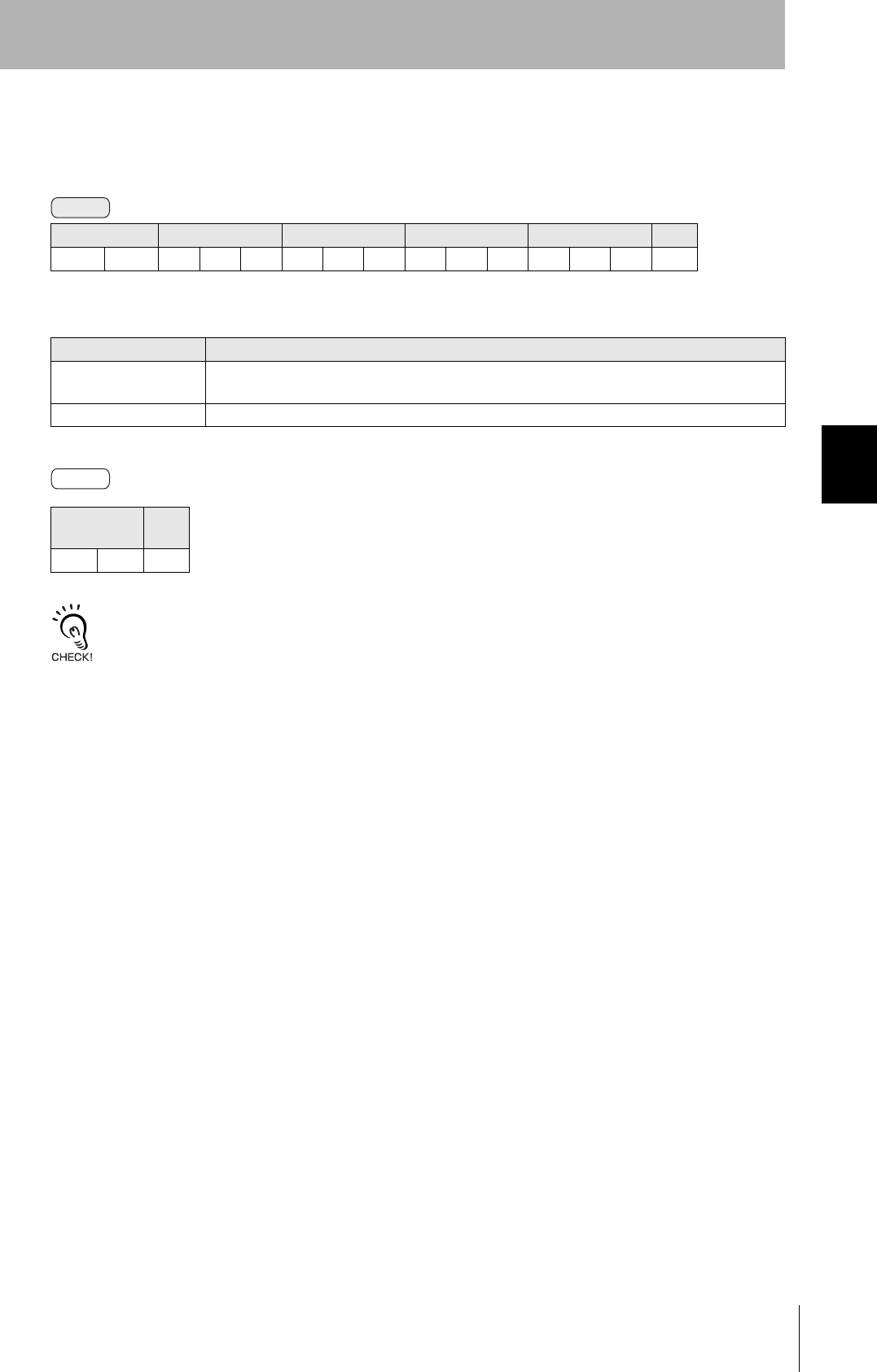
Performs a communications test on communications between the host device and Amplifier Unit.
When an Amplifier Unit receives a test command, it sends the response code and command test data
to the host device as the response.
* Number of data n < 136 (2-character units)
The response code (when normal: 00) and the received test data are returned.
Example: Performing a Test for the Amplifier Unit Using the Data 12345678
Command code Test data CR
Data 1 ••• Data n
10 0Dh
Parameter Description
Parameter Description
Test data The data to be sent in the test is specified with a hexadecimal value. (270 characters max.)
However, note that odd numbers of characters cannot be used.
Response
code
Test data CR
Data 1 ••• Data n
00 0Dh
Command code Test data CR
Data 1 Data 2 Data 3 Data 4
1 0 123456780Dh
Response
code
Test data CR
Data 1 Data 2 Data 3 Data 4
00123456780Dh
Command
Response
Command
Response
43
CIDRW System
User’s Manual
SECTION 4
Command/Response Format
SECTION 4
Reading from/Writing to ID Tags
■NAK
Sends the response made immediately before again.
Sends the response made immediately before again.
A response will not be returned if a NAK command is executed immediately after startup.
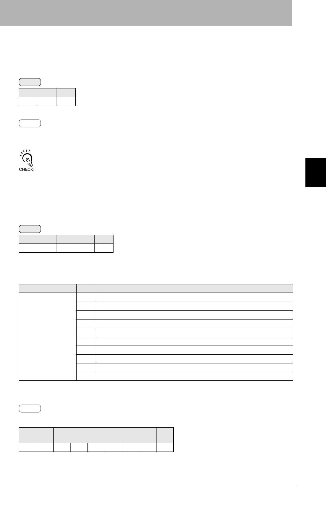
■GET PARAMETER
This command gets the model number, firmware version, or another parameter.
The response code (00: normal) and received parameter value are returned.
* The contents and length of the parameter value depend on the parameter type that is specified for the command.
Command code CR
120Dh
Command code Parameter type CR
14 0Dh
Parameter Description
Parameter Value Description
Parameter type 01 Model number
02 Firmware version
03 MAC address
10 DIP switch enabled/disabled status
11 IP address on DIP switch
12 Subnet address on DIP switch
13 IP address in ROM
14 Subnet address in ROM
20 Memory status
21 Antenna connection status
Response
code Parameter value CR
00 0Dh
Command
Response
Command
Response

44
SECTION 4
Command/Response Format
CIDRW System
User’s Manual
SECTION 4
Reading from/Writing to ID Tags
Example 1: Getting the Model Number of Amplifier Unit
The product model number is returned as an ASCII text string.
Example 2: Getting the Firmware Version of Amplifier Unit
The response code (00: normal) and firmware version are returned as a 4-digit decimal number.
* The above response is for a firmware version of 1.00.
Example 3: Getting the MAC Address of Amplifier Unit
Command code Parameter
type CR
14010Dh
Response
code Model number CR
0 0 V640-HAM11 -V30Dh
Command code Parameter
type CR
14020Dh
Command code Parameter
type CR
14030Dh
Command
Response
Command
Response
Response code Firmware version CR
0 0 01000Dh
Major version Minor version
Command

45
CIDRW System
User’s Manual
SECTION 4
Command/Response Format
SECTION 4
Reading from/Writing to ID Tags
The response code (00: normal) and MAC address are returned.
* The above response is for a MAC address of 00:1F:16:1A:B9:8E.
Example 4: Checking If Network Settings on DIP Switch on Amplifier Unit Are Enabled or Disabled
The response code (00: normal) and enabled/disabled status of the DIP switch network settings are
returned.
* The above response is for when the DIP switch settings are enabled. The response will show 00 for disabled status.
Example 5: Checking IP Address on DIP Switch on Amplifier Unit
The response code (00: normal) and IP address on the DIP switch (decimal, four octets of 3 digits
each) are returned.
* The above response is for when the IP address on the DIP switch is 192.168.1.20.
* The following response will be returned if the DIP switch network settings are disabled.
Response code MAC address CR
0 0 001F161AB98E0Dh
Command code Parameter
type CR
14100Dh
Response
code
DIP switch
enabled/disabled CR
00 0 10Dh
Command code Parameter
type CR
14110Dh
Response
Command
Response
Command
Response
Response code IP address on DIP switch CR
0 0 1921680010200Dh
First octet Second octet Third octet Fourth octet
Response code IP address on DIP switch CR
0 0 0000000000000Dh
First octet Second octet Third octet Fourth octet

46
SECTION 4
Command/Response Format
CIDRW System
User’s Manual
SECTION 4
Reading from/Writing to ID Tags
Example 6: Checking the Subnet Mask on the DIP Switch of Amplifier Unit
The response code (00: normal) and subnet mask (decimal, four octets of 3 digits each) are returned.
* The subnet mask is always 255.255.255.0 regardless of whether the DIP switch network settings are enabled or disabled.
Example 7: Checking IP Address in ROM
The response code (00: normal) and IP address in ROM (decimal, four octets of 3 digits each) are
returned.
* The above response is for when the IP address in ROM is 192.168.1.200.
Example 8: Checking the Subnet Mask in ROM
The response code (00: normal) and subnet mask (decimal, four octets of 3 digits each) are returned.
* The above response is for when the subnet mask in ROM is 255.255.255.0.
Command code Parameter
type CR
14120Dh
Command code Parameter
type CR
14130Dh
Command code Parameter
type CR
14140Dh
Command
Response
Response code Subnet mask on DIP switch CR
0 0 2552552550000Dh
First octet Second octet Third octet Fourth octet
Command
Response
Response code IP address on DIP switch CR
0 0 1921680012000Dh
First octet Second octet Third octet Fourth octet
Command
Response
Response code IP address on DIP switch CR
0 0 2552552550000Dh
First octet Second octet Third octet Fourth octet

47
CIDRW System
User’s Manual
SECTION 4
Command/Response Format
SECTION 4
Reading from/Writing to ID Tags
Example 9: Getting the Memory Status of Amplifier Unit
The response code (00: normal) and memory check results for internal EEPROM are returned.
* The above response is for normal memory status. The response will show 00 for error status.
Example 10: Getting the Antenna Connection Status of Amplifier Unit
The response code (00: normal) and Antenna connection status are returned.
* The above response is for normal Antenna connection status. The response will show 00 for error status.
Command code Parameter
type CR
14200Dh
Response
code
DIP switch
enabled/disabled CR
00 0 10Dh
Command code Parameter
type CR
14210Dh
Response
code
DIP switch
enabled/disabled CR
00 0 10Dh
Command
Response
Command
Response

48
SECTION 4
Command/Response Format
CIDRW System
User’s Manual
SECTION 4
Reading from/Writing to ID Tags
■GET LAST COMMAND
Gets the command code of the last command that was executed.
This command returns the command code of the last command that was executed.
When There Is a Previously Executed Command
* The command code is given as two or four characters.
When There Is No Previously Executed Command
■GET COMMUNICATIONS HISTORY
This command gets the history of communications from when the power was turned ON (total number
of communications, total successful communications, and total number of failed communications).
This command returns the history of communications from when the power was turned ON. Four hexa-
decimal digits each are returned for the total number of communications, total number of successful
communications, and total number of failed communications.
If the total number of communications exceeds 65,535, all data in the communications history will be
reset to 0.
Command code CR
150Dh
Response
code Command code CR
00 0Dh
Response
code
Command
code CR
00000Dh
Command code CR
160Dh
Response
code
Total number of com-
munications
Total number of suc-
cessful communica-
tions
Total number of failed
communications CR
00 0Dh
Command
Response
Command
Response
49
CIDRW System
User’s Manual
SECTION 4
Command/Response Format
SECTION 4
Reading from/Writing to ID Tags
Example 1: Getting the Communications History of Amplifier Unit
The following response is returned if there are 32,000 total communications, 30,000 successful communications, and
2,000 failed communications.
■CLEAR COMMUNICATIONS HISTORY
This command clears the communications history.
■NOISE MEASUREMENT
The levels of noise in the vicinity of the CIDRW Head are measured and the noise level is expressed
numerically in the range "00" to "99."
The response code (when normal: 00) and the noise level "00" to "99" are returned.
Influence of background noise on communications distance Refer to page 110.
Command code CR
160Dh
Response
code
Total number of com-
munications
Total number of suc-
cessful communica-
tions
Total number of failed
communications CR
0 0 7D00753007D00Dh
Command code CR
170Dh
Response
code CR
000Dh
Command code CR
400Dh
Response code Noise level CR
00 0Dh
Command
Response
Command
Response
Command
Response
50
SECTION 4
Command/Response Format
CIDRW System
User’s Manual
SECTION 4
Reading from/Writing to ID Tags
■RESET
All Amplifier Unit processing is stopped, and the initial status is re-established.
There is no response to this command.
■SET WEB PASSWORD
This command sets the Web password.
When the Password Is Not Set
* Only the following characters can be used in passwords: 0 to 9, a to z, and A to Z. If any other characters are used, error 14 will
occur.
* If the password is not between 1 and 16 characters long, error 14 will occur.
When the Password Is Not Set
Never turn OFF the power supply to the Amplifier Unit before a response is received from the Amplifier Unit for this
command. Doing so may damage the Amplifier Unit.
Command code CR
7F0Dh
Command code Password (1 to 16 characters) CR
A2 0Dh
Command code CR
A20Dh
Response
code CR
000Dh
Command
Response
Command
Response
51
CIDRW System
User’s Manual
SECTION 4
Command/Response Format
SECTION 4
Reading from/Writing to ID Tags
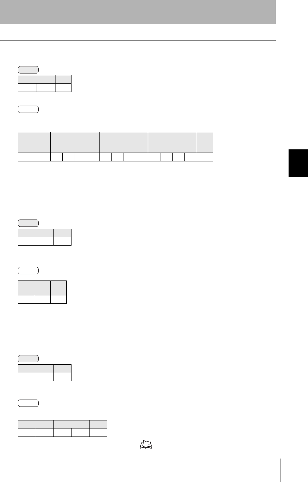
■SET NETWORK
This command sets the IP address and subnet mask in ROM.
* If an error occurs when writing to EEPROM, error 9A will be returned.
Never turn OFF the power supply to the Amplifier Unit before a response is received from the Amplifier Unit for this
command. Doing so may damage the Amplifier Unit.
Command code First octet Second octet Third octet Fourth octet CR
A3 0Dh
Parameter Description
Parameter Description
Type IP address setting: 00
Subnet mask setting: 01
First to fourth octets The address is set in decimal in four octets of three characters each.
Response
code CR
000Dh
Command
Response

52
SECTION 4
Command/Response Format
CIDRW System
User’s Manual
SECTION 4
Reading from/Writing to ID Tags
MEMO

SECTION 5
Browser Interface
53
CIDRW System
User’s Manual
SECTION 5
Browser Interface
Browser Operation Windows 54
Window Configuration 55

54
SECTION 5
Browser Operation Windows
CIDRW System
User’s Manual
SECTION 5
Browser Interface
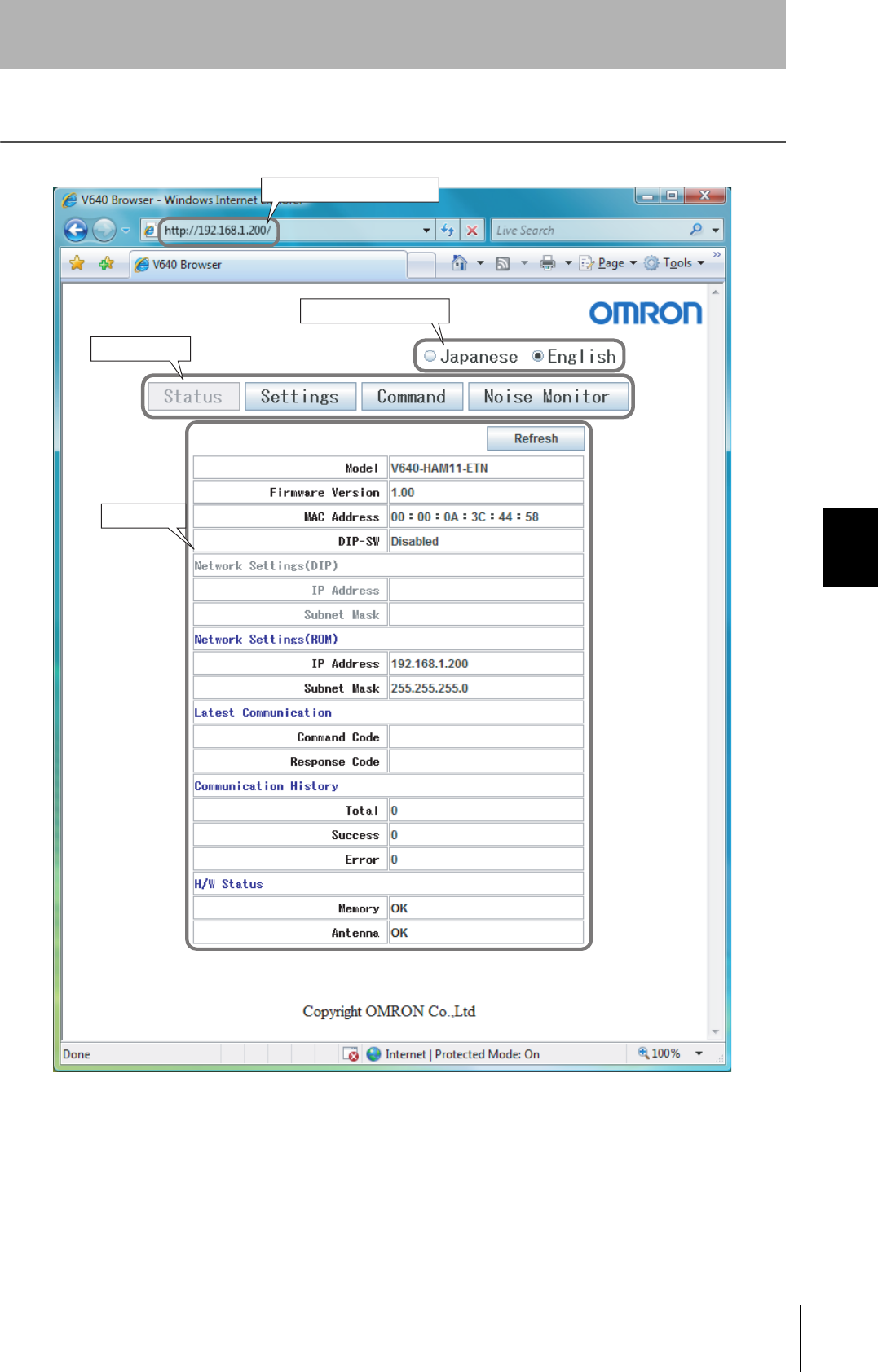
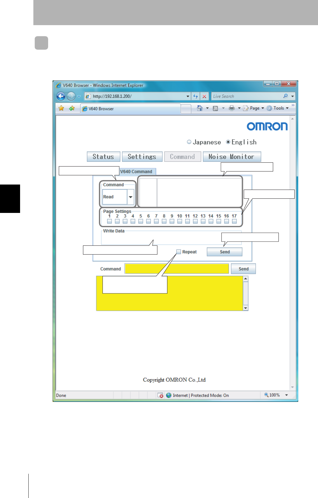
Browser Operation Windows
To operate an Amplifier Unit from a browser, connect the Ethernet cables, start a browser on the computer,
and specify the IP address of the Amplifier Unit as the URL. The Browser Window will be displayed. The
Status Window will be displayed first. (If a Web password is set, the Status Window will be displayed after the
Password Entry Window.) Menu buttons to move to the other windows are provided at the top of the window.
Click a menu button to move to another window.
Precautions
• Before starting the Browser Window, make sure that Java Runtime Environment (JRE) 5.0 or higher is
installed on the computer.
Java software can be downloaded for free from the following URL: http://www.java.com/ja/.
(Java and all trademarks and logos related to Java are trademarks or registered trademarks of Sun
Microsystems, Inc., in the USA and other countries.)
• Before starting the Browser Window, make sure that the Amplifier Unit is not executing a command from
terminal software or another source. The Amplifier Unit must be in idling status. If the Browser Window is
started while the Amplifier Unit is executing a command, responses will not be returned for the commands
sent from the terminal software or Browser Window.
• Access is possible from only one browser at a time. If the Amplifier Unit is accessed from another browser
(B) while it is connected to a browser (A), the control right will move to browser B.
55
CIDRW System
User’s Manual
SECTION 5
Window Configuration
SECTION 5
Browser Interface
Window Configuration
IP address of Amplifier Unit
Language Buttons
Menu Buttons
Main Display
56
SECTION 5
Window Configuration
CIDRW System
User’s Manual
SECTION 5
Browser Interface
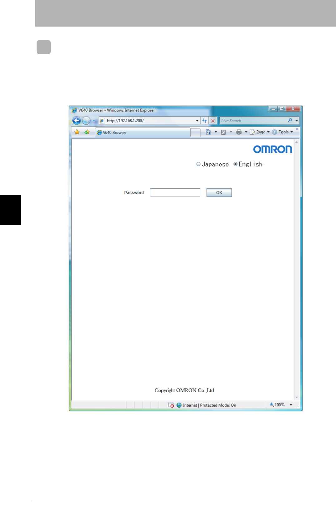
Password Entry Window
If a Web password is set in the Amplifier Unit, the Password Entry Window will be displayed before the
Browser Window is displayed. Enter the password and click the OK Button in this window. If the pass-
word is correct, the Status Window will be displayed.
The following characters can be used for the password: 0 to 9, a to z, and A to Z.
57
CIDRW System
User’s Manual
SECTION 5
Window Configuration
SECTION 5
Browser Interface
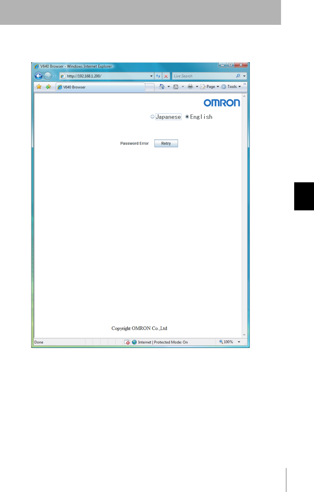
If the password is not correct, the following window will be displayed.
Click the Retry Button. The Password Entry Window will be displayed again.
58
SECTION 5
Window Configuration
CIDRW System
User’s Manual
SECTION 5
Browser Interface
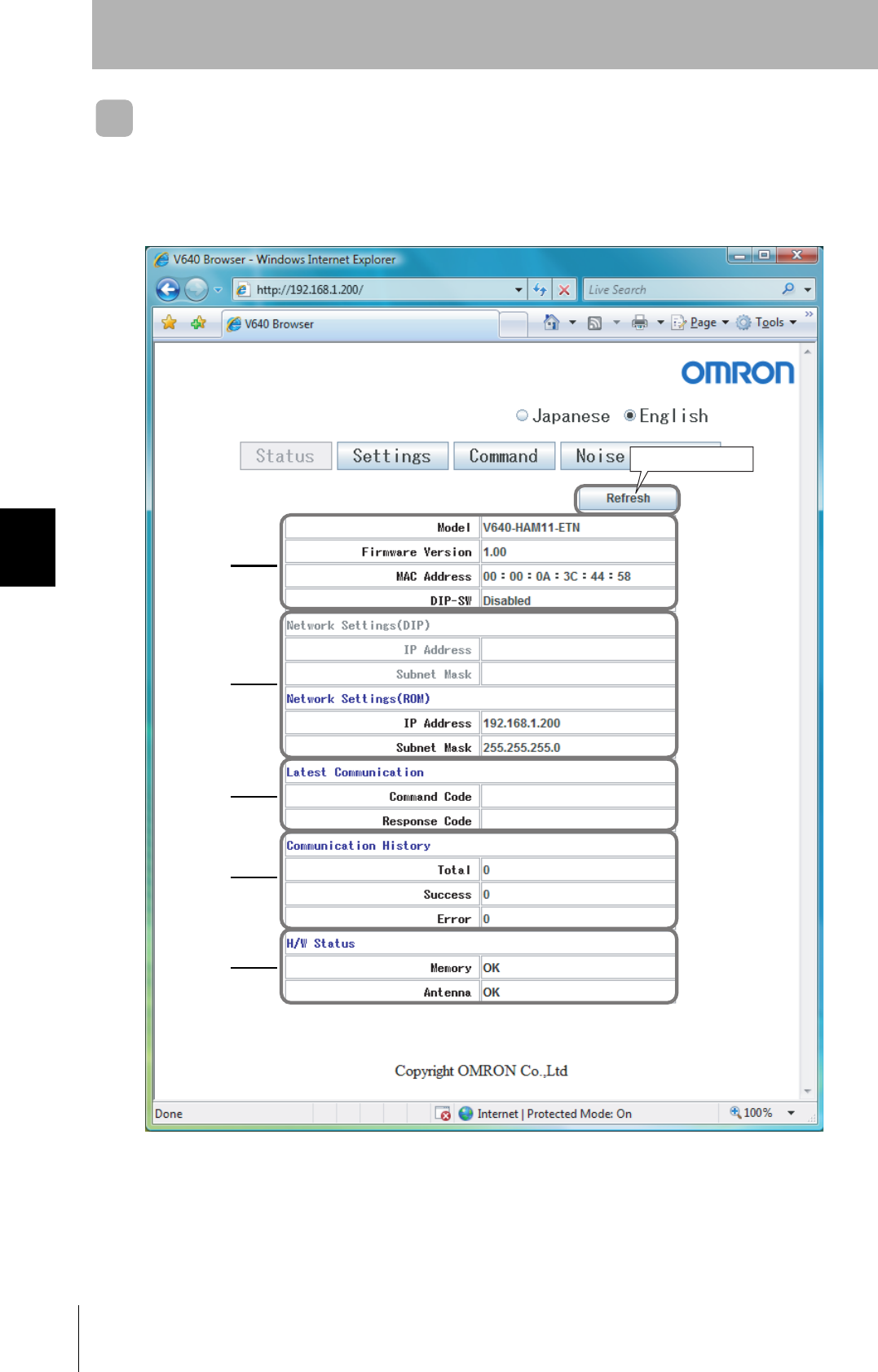
Status Window
The Status Window displays the model number, firmware version, MAC address, and other information
on the Amplifier Unit so that you can check it. Click the Refresh Button at the top of the window to
update the displayed information (latest communication, communication history, and H/W status).
Refresh Button
A
B
C
D
E

59
CIDRW System
User’s Manual
SECTION 5
Window Configuration
SECTION 5
Browser Interface
AAmplifier Unit Information
BNetwork Setting Information
CLast Command Information
DCommunications History Information
EHardware Information
Item Description Comments
Model The product model number is displayed.
Firmware Version The firmware version is displayed.
MAC Address The MAC address is displayed.
DIP-SW "Enabled" is displayed if the Amplifier Unit is set to use the IP address
that is set on the DIP switch. "Disabled" is displayed if the Amplifier
Unit is set to use the IP address that is set in ROM.
Item Description Comments
Network Settings(DIP) If the Amplifier Unit is set to use the IP address that is set on the DIP
switch, this item is displayed in blue, and the IP address and subnet
mask of the Amplifier Unit are displayed.
If the Amplifier Unit is set
to use the IP address that
is set on the DIP switch,
this item is grayed out.
IP Address
Subnet Mask
Network Settings(ROM) If the Amplifier Unit is set to use the IP address that is set in ROM, this
item is displayed in blue, and the IP address and subnet mask of the
Amplifier Unit are displayed.
If the Amplifier Unit is set
to use the IP address that
is set in ROM, this item is
grayed out.
IP Address
Subnet Mask
Item Description Comments
Latest Communication The last command code that was executed and the last response code
that was returned by the Amplifier Unit are displayed.
Nothing is displayed if a
command has not been
executed since the
Amplifier Unit was
started.
Command Code
Response Code
Item Description Comments
Communication History History information on communications with the ID Tags is displayed.
Total Total number of communications
Success Total number of successful communications
Error Total number of failed communications
Item Description Comments
H/W Status Hardware information is displayed. "OK" is displayed for nor-
mal status.
Memory "Error" is displayed if a memory error was detected during the memory
check at startup.
Antenna "Error" is displayed if an error is detected in the CID Head that is con-
nected to the Amplifier Unit (or if a CID Head is not connected).
60
SECTION 5
Window Configuration
CIDRW System
User’s Manual
SECTION 5
Browser Interface
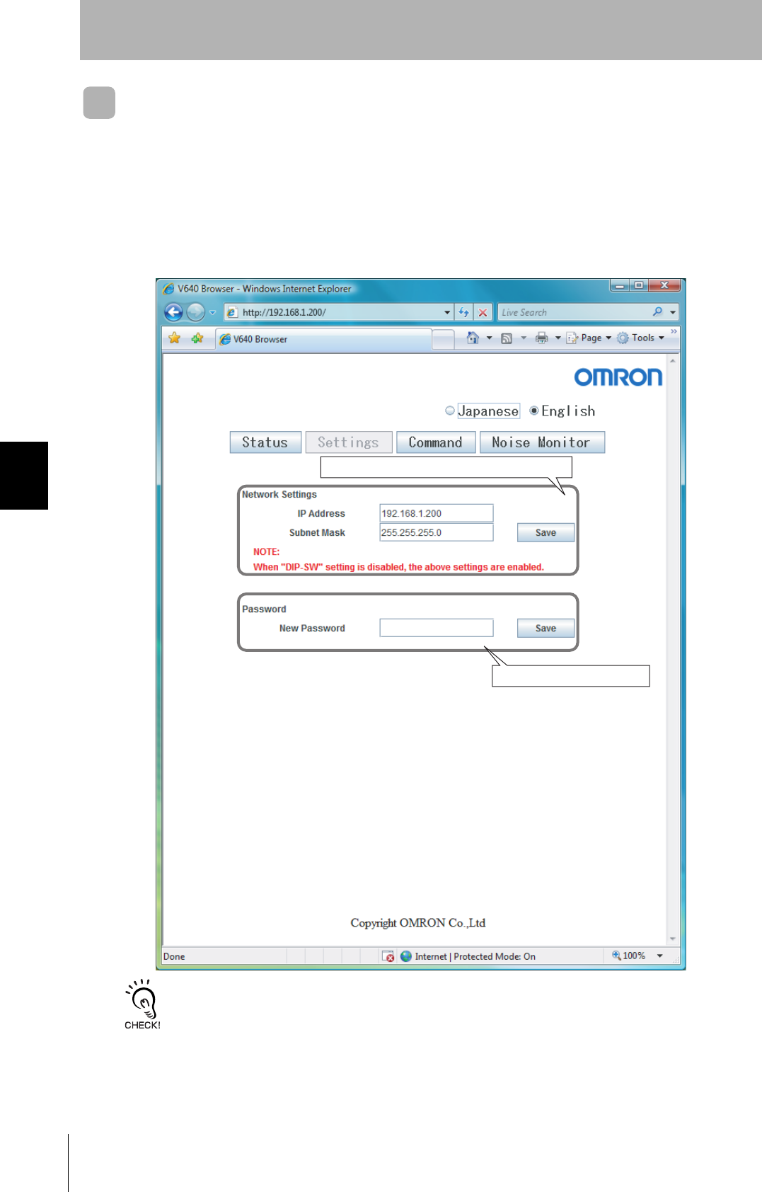
Setting Window
The network settings (IP address and subnet mask) of the Amplifier Unit and the Web password can
be set in the Setting Window. The values that are set are enabled when the Amplifier Unit is restarted.
If the Save Button is clicked when the password box is empty, the Web password will be cleared. In
this state, the browser interface can be used without entering the Web password.
The following characters can be used for the Web password: 0 to 9, a to z, and A to Z.
Never turn OFF the power supply to the Amplifier Unit before a response is received after clicking the Save Button.
Doing so may damage the Amplifier Unit.
IP address and subnet mask setting area
Web password setting area

61
CIDRW System
User’s Manual
SECTION 5
Window Configuration
SECTION 5
Browser Interface
Command Window
The Command Window can be used to communicate with ID Tags. The Command Window has two
tab pages: "CID R/W" and "V640 Command."
CID R/W V640 Command
62
SECTION 5
Window Configuration
CIDRW System
User’s Manual
SECTION 5
Browser Interface
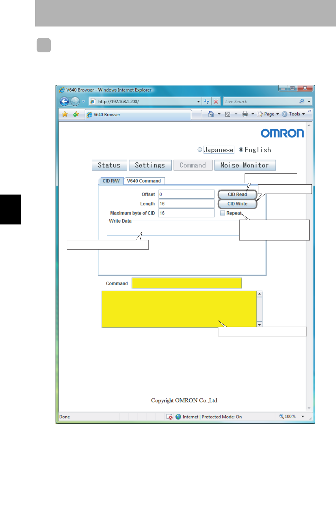
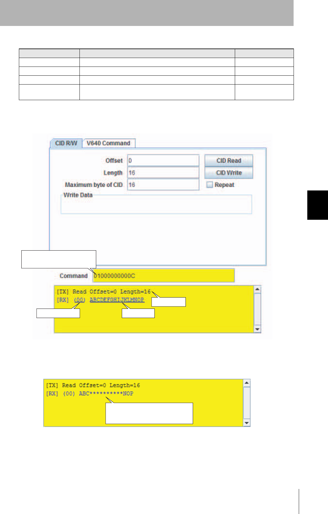
CID R/W Tab Page
The CID R/W Tab Page allows you to read or write ID Tag data by specifying the offset, length, and
maximum bytes of CID. If writing is executed, you must also specify the write data.
CID Read Button
CID Write Button
Select this check box to
repeat the command.
Write Data Designation Area
Communications Results Display Area
63
CIDRW System
User’s Manual
SECTION 5
Window Configuration
SECTION 5
Browser Interface
For example, the results display would be as shown below if a CID read was executed with an offset of
0, a length of 16, and a maximum bytes of CID of 16.
Only visible ASCII characters can be used to read and write data on the CID R/W Tab Page. If charac-
ters that are not visible ASCII characters are detected for a CID read, they will be converted to aster-
isks (*).
Item Description Comments
Offset Specify the CID offset between 0 and 15 bytes.
Length Specify the CID length between 1 and 16 bytes.
Maximum byte of CID Specify the maximum CID length between 1 and 16 bytes.
Write Data For the write data, specify only the number of bytes for the specified
length.
Specify only visible ASCII
characters.
Command sent to Amplifier
Unit
Send data
Receive data
Response code
Characters that are not visible ASCII
characters are converted to "*".
64
SECTION 5
Window Configuration
CIDRW System
User’s Manual
SECTION 5
Browser Interface
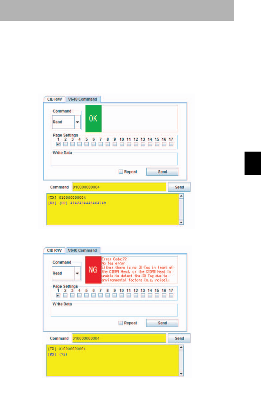
V640 Command Tab Page
The V640 Command Tab Page allows you to read and write data according to the command format of
the Amplifier Unit
OK/NG Display Area
Page Designation Area
Send Button
Page/Write Designation Area
Write Data Designation Area
Select this check box to
repeat the command.
65
CIDRW System
User’s Manual
SECTION 5
Window Configuration
SECTION 5
Browser Interface
■Page/Write Designation Area
Select Read or Write in the Page/Write Designation Area.
■OK/NG Display Area
The command execution results will be displayed as "OK" or "NG" in the OK/NG Display Area. If "NG"
is displayed, information on the error will be displayed.
• Successful Communications
• Failed Communications

66
SECTION 5
Window Configuration
CIDRW System
User’s Manual
SECTION 5
Browser Interface
■Page Designation Area
Select the check boxes to specify the pages to be read or written.
■Write Data Designation Area
When writing data, specify the data to write to the ID Tag as a hexadecimal string. Specify 16 charac-
ters for each page that you specify in the Page Designation Area.
67
CIDRW System
User’s Manual
SECTION 5
Window Configuration
SECTION 5
Browser Interface
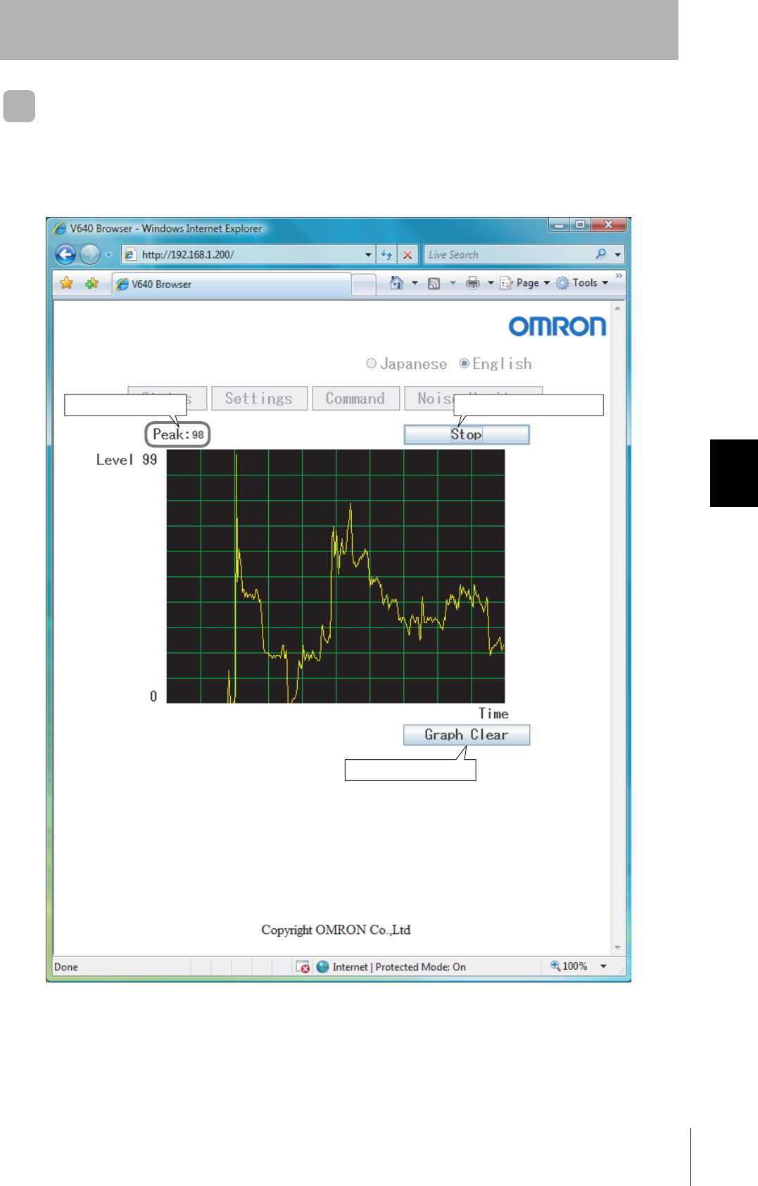
Noise Measurement Window
The Noise Measurement Window allows you to continuously send the NOISE MEASUREMENT com-
mand to the Amplifier Unit and display the results in realtime.
The horizontal axis gives the time and the vertical axis gives the noise level (0 to 99).
Peak noise level Start/Stop Button
Graph Clear Button

68
SECTION 5
Window Configuration
CIDRW System
User’s Manual
SECTION 5
Browser Interface
MEMO