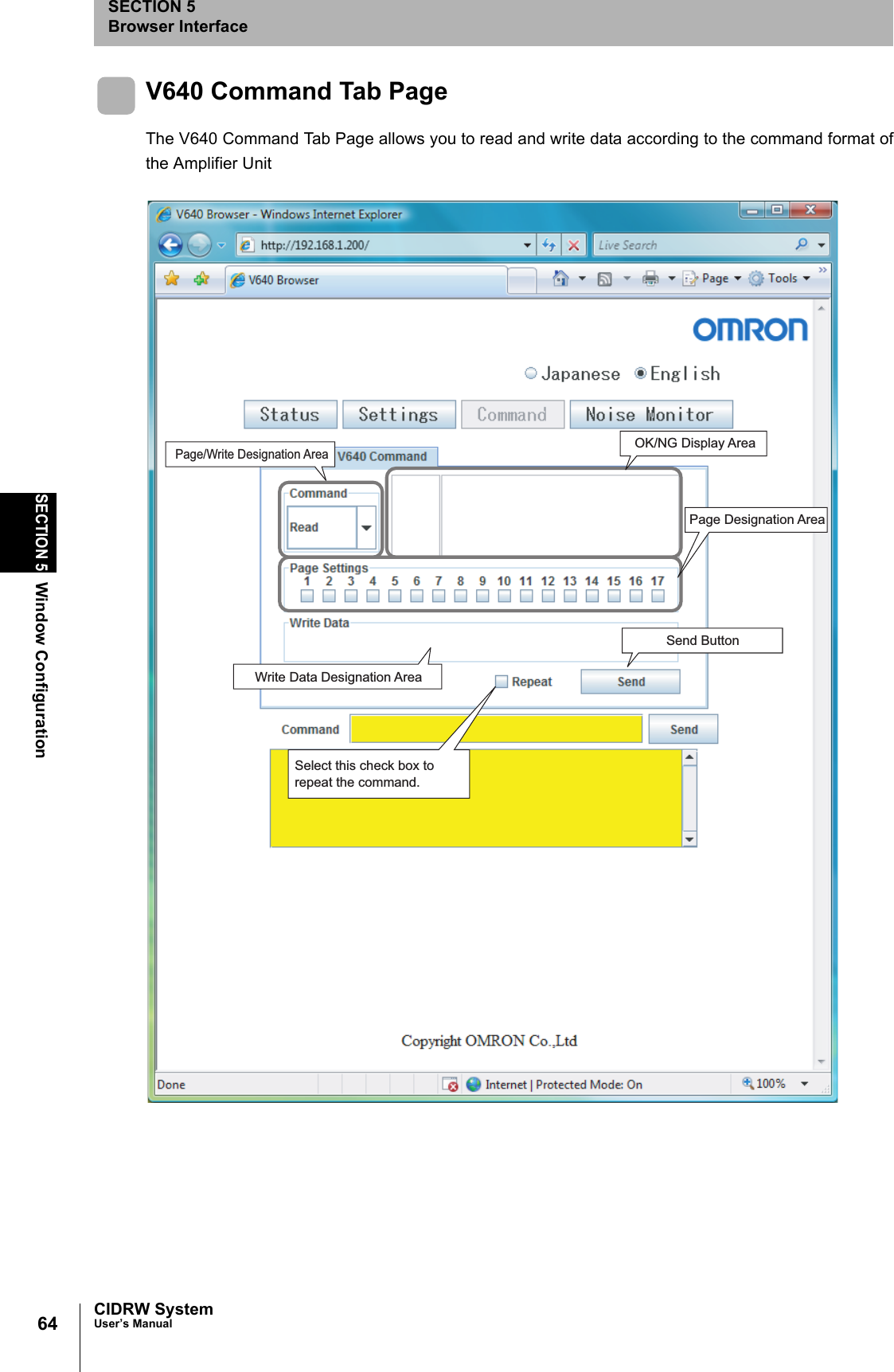
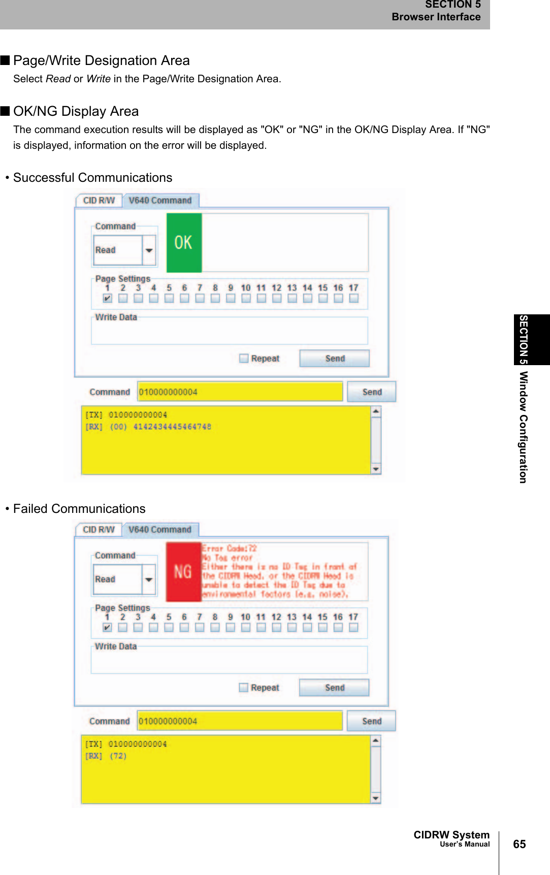
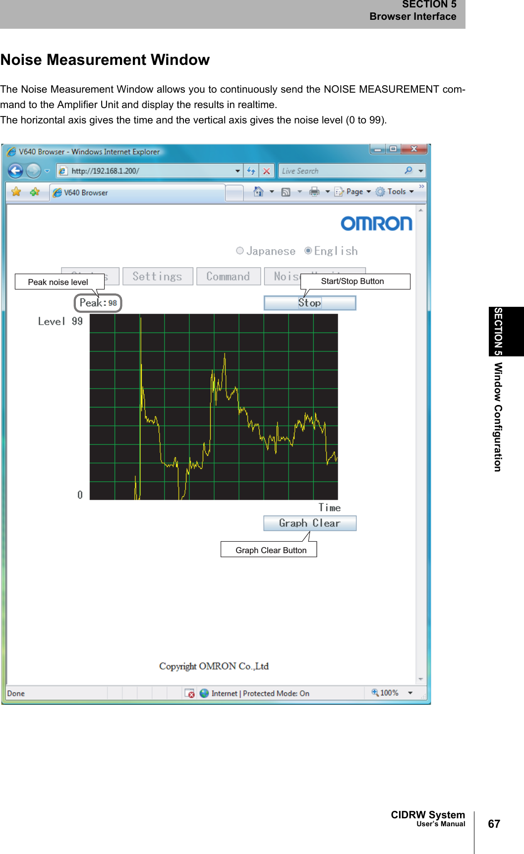
Omron V640HAM11 Carrier ID Reader/Writer (RFID) User Manual Z308 E1 01
Omron Corporation Carrier ID Reader/Writer (RFID) Z308 E1 01
Omron >
Contents
- 1. User manual(ETN)
- 2. User manual(V3)
- 3. User manual2& 65288;ETN)
- 4. User manual2& 65288;V3)
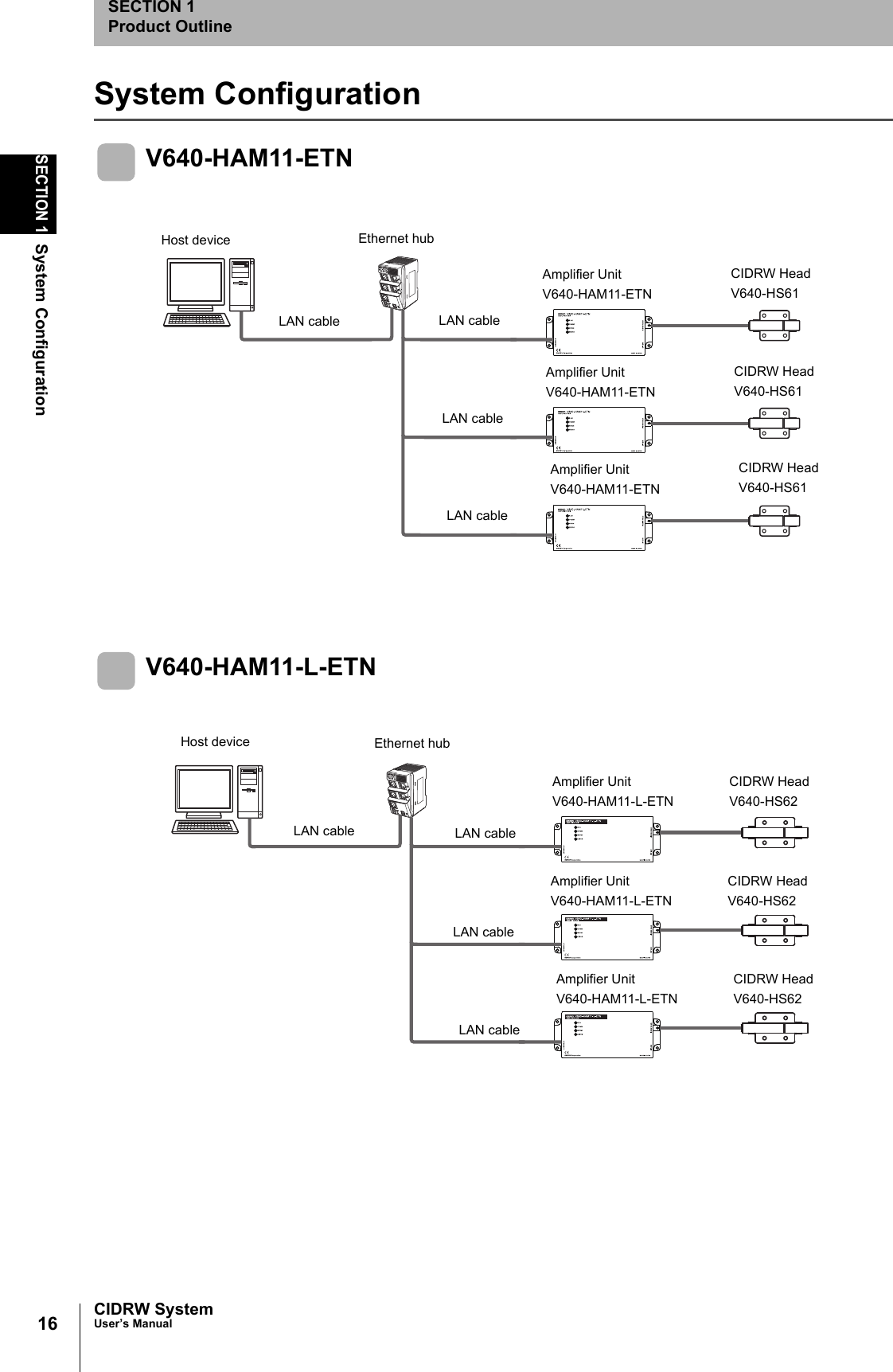
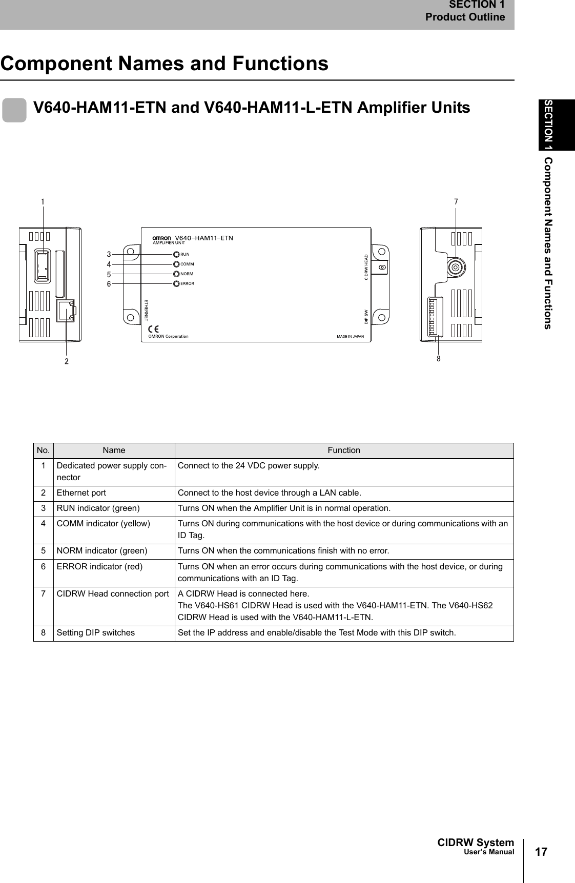
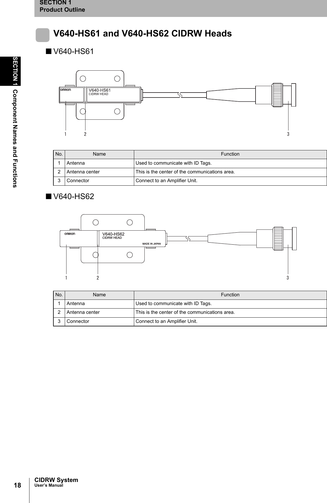
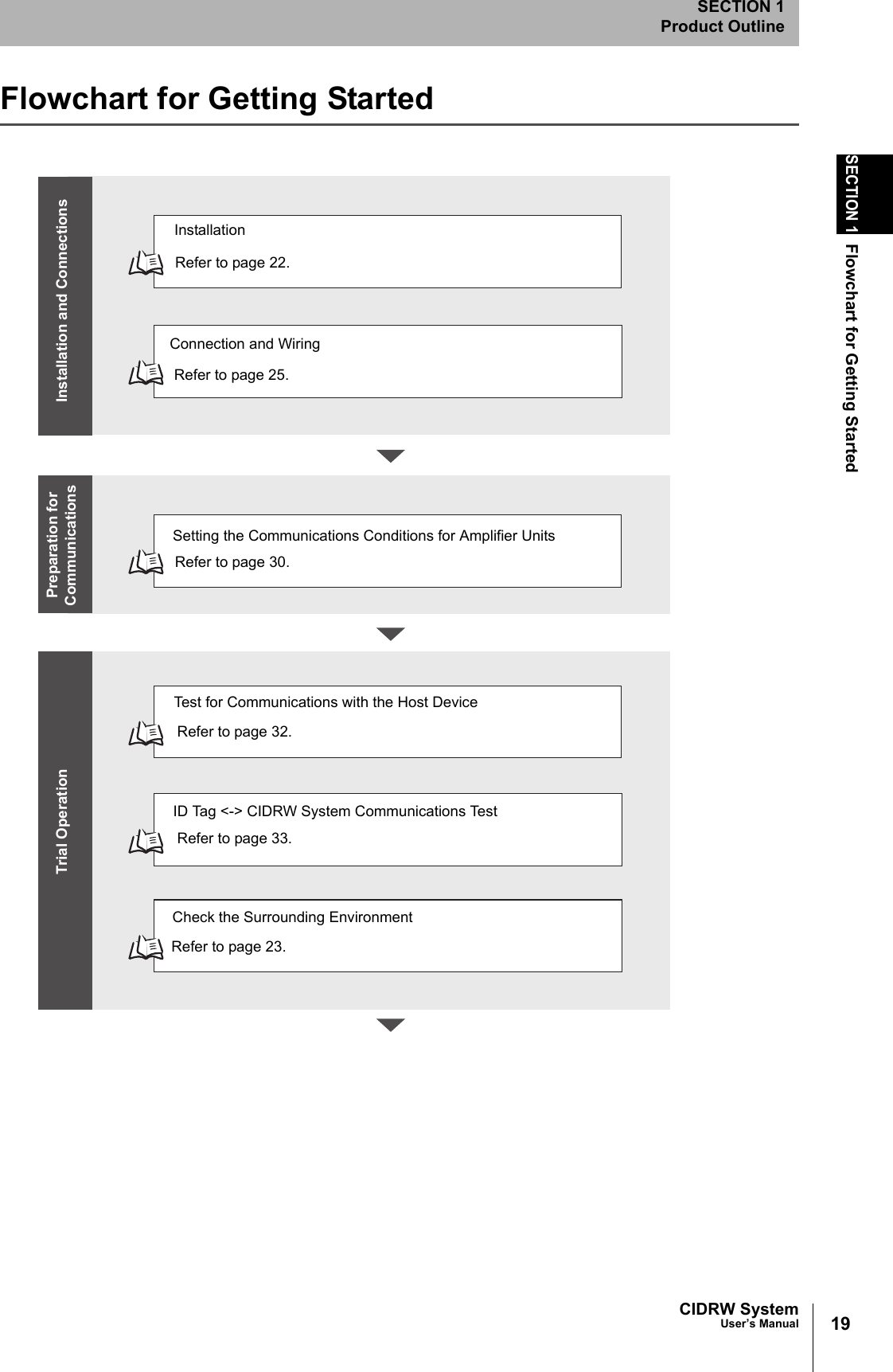
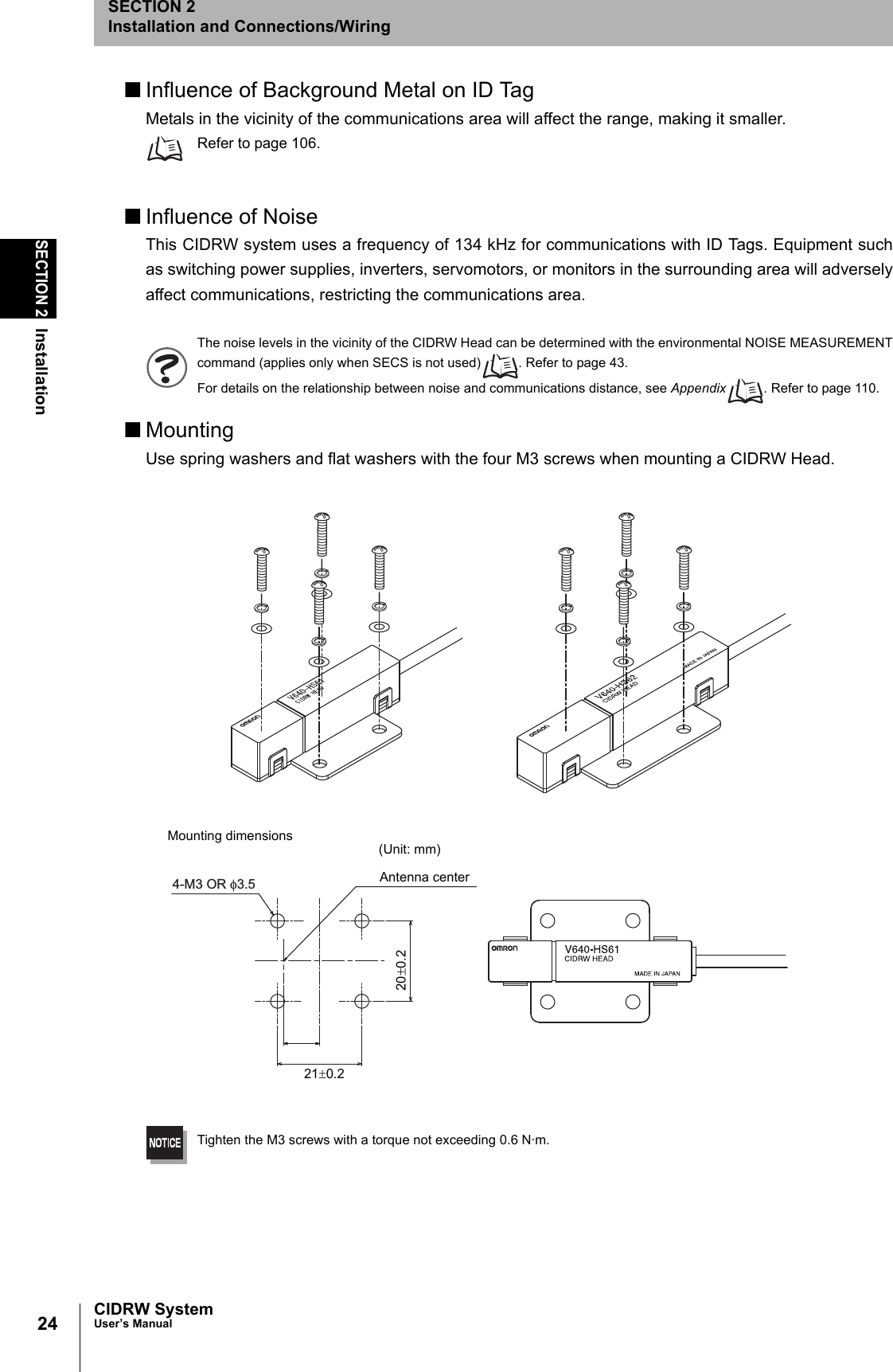
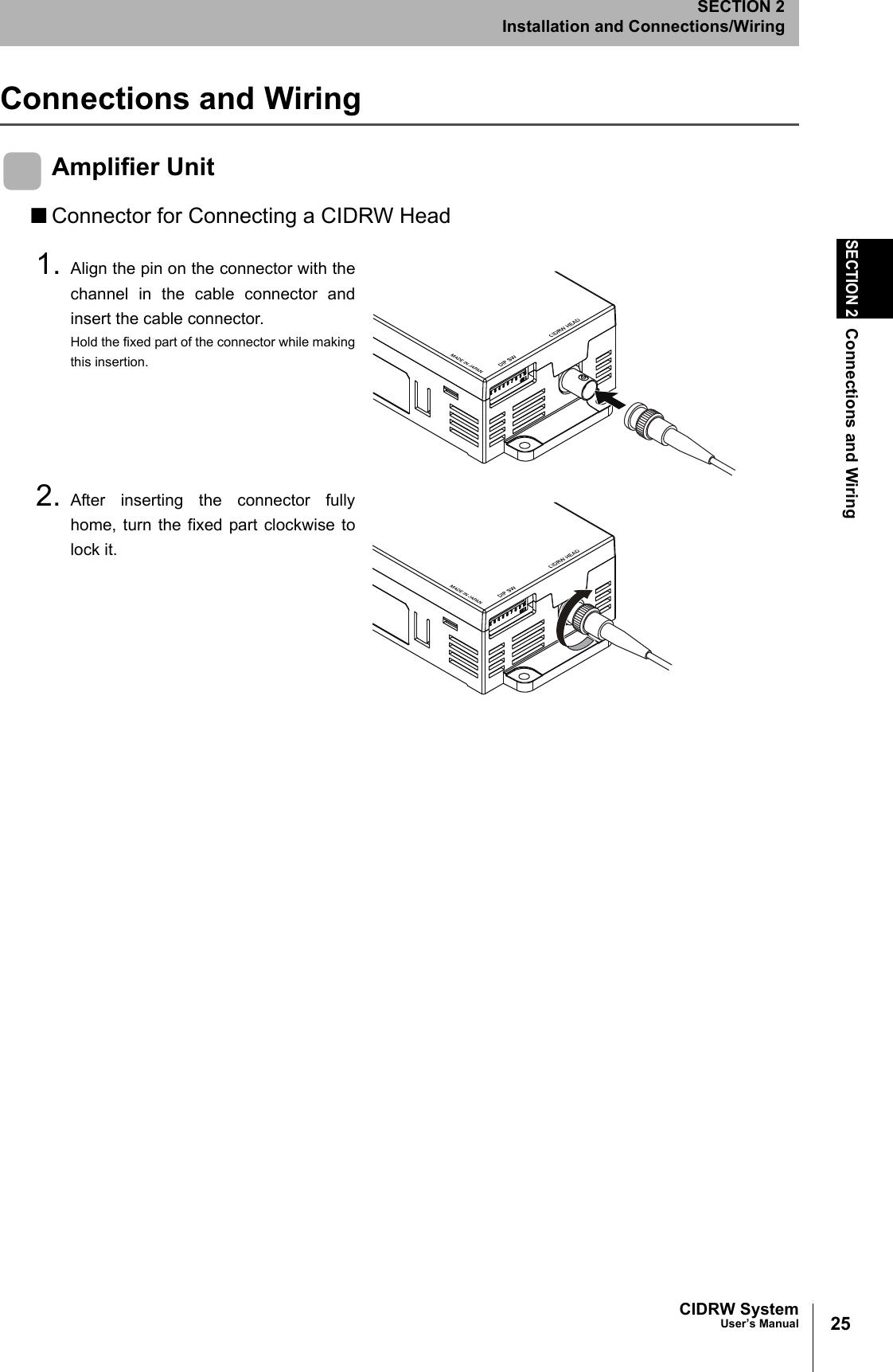
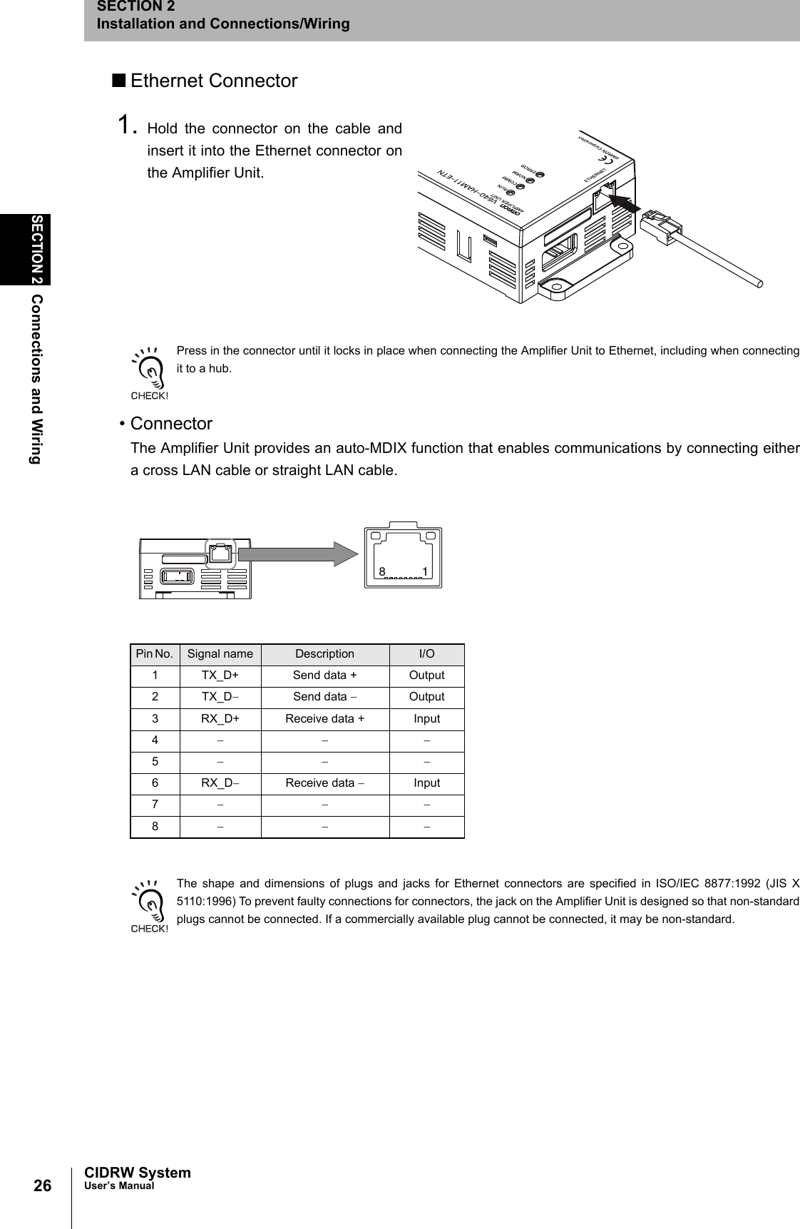
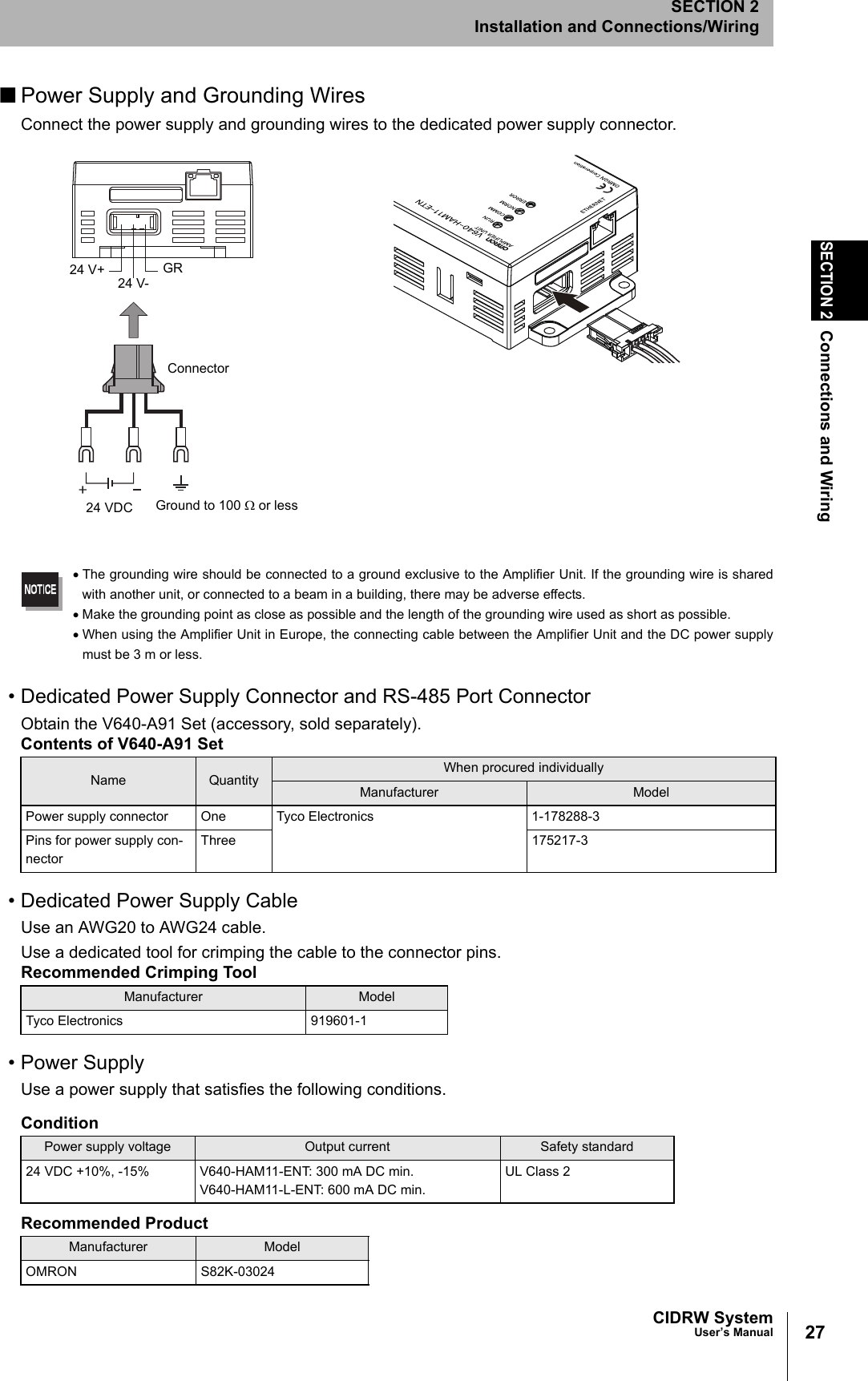
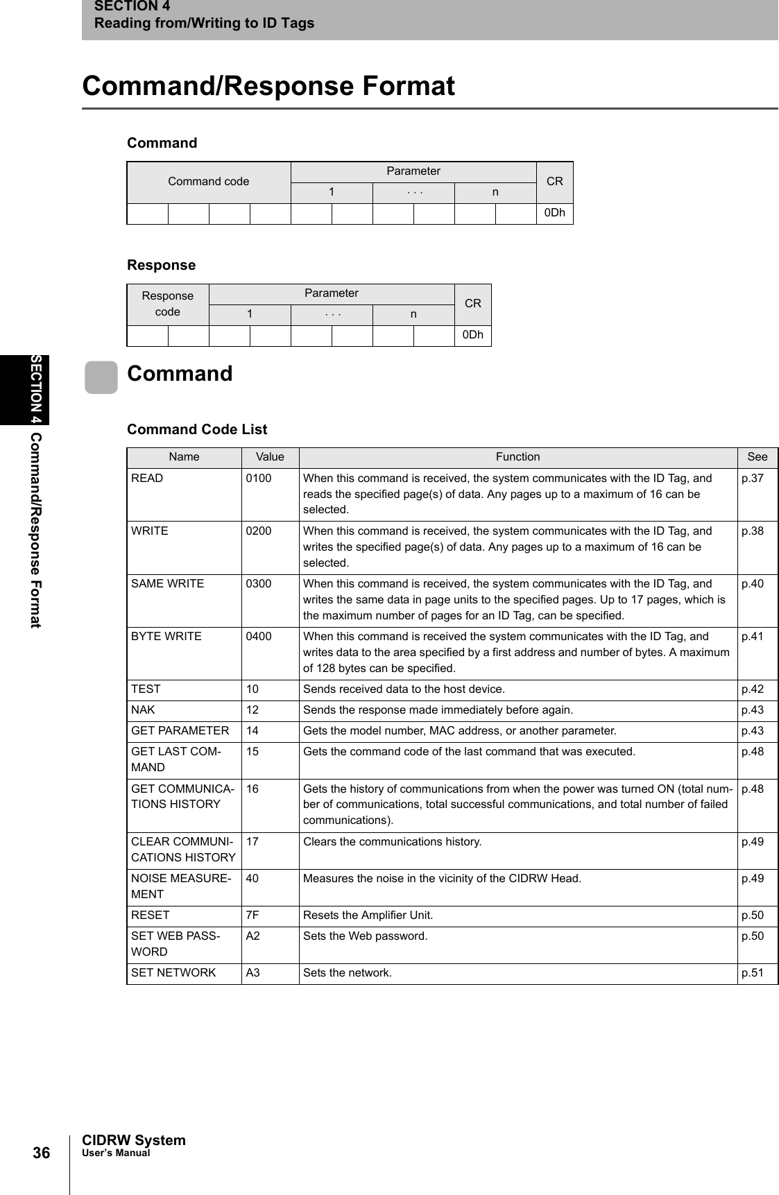
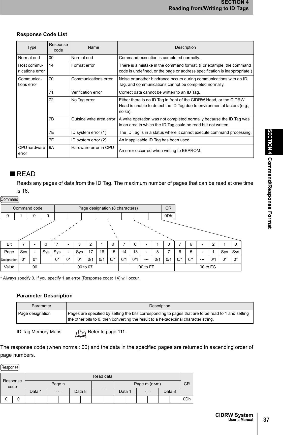
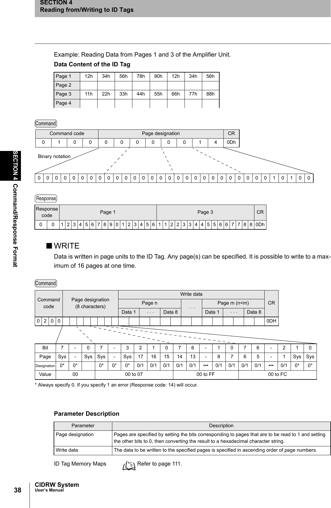
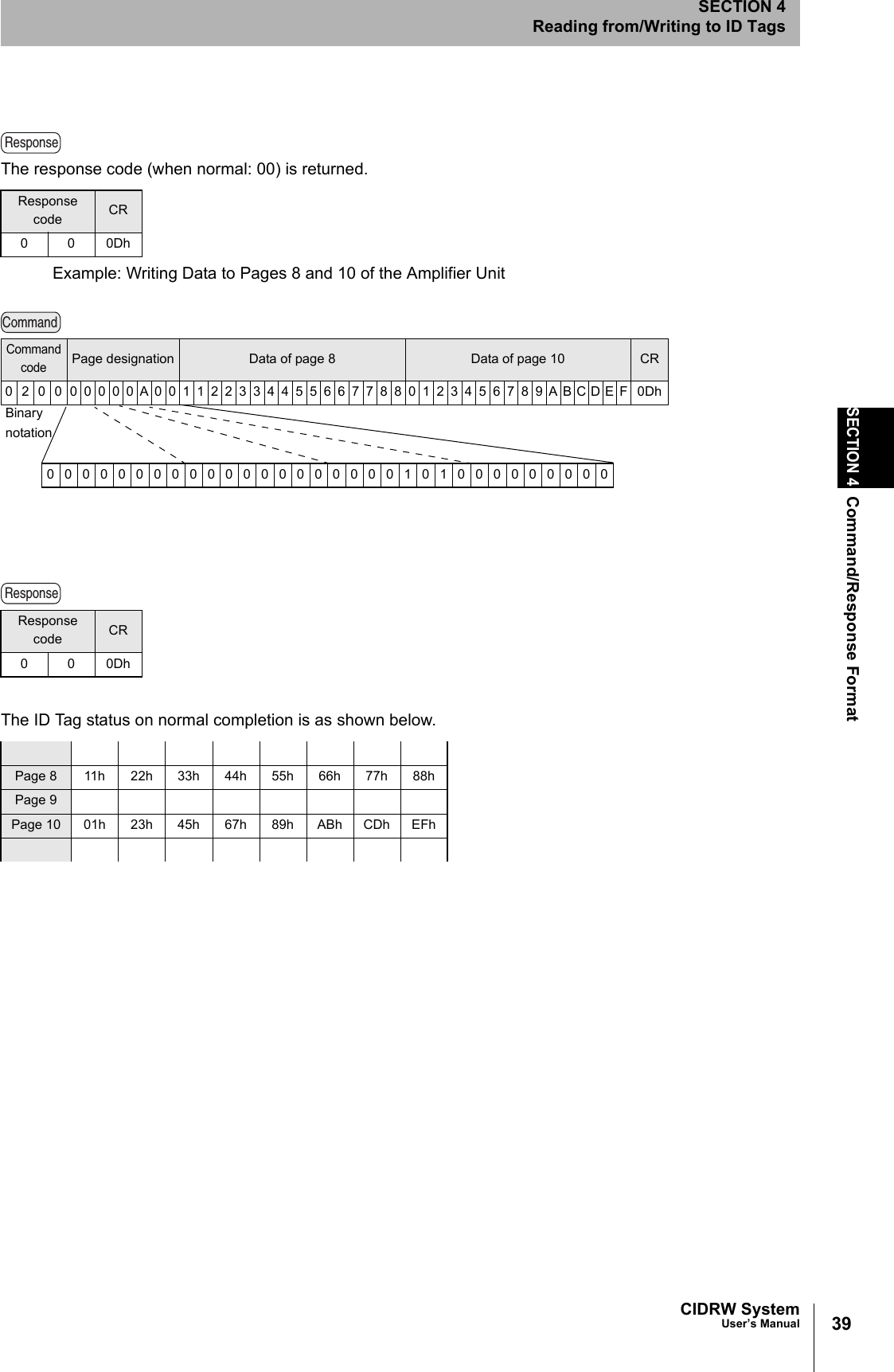
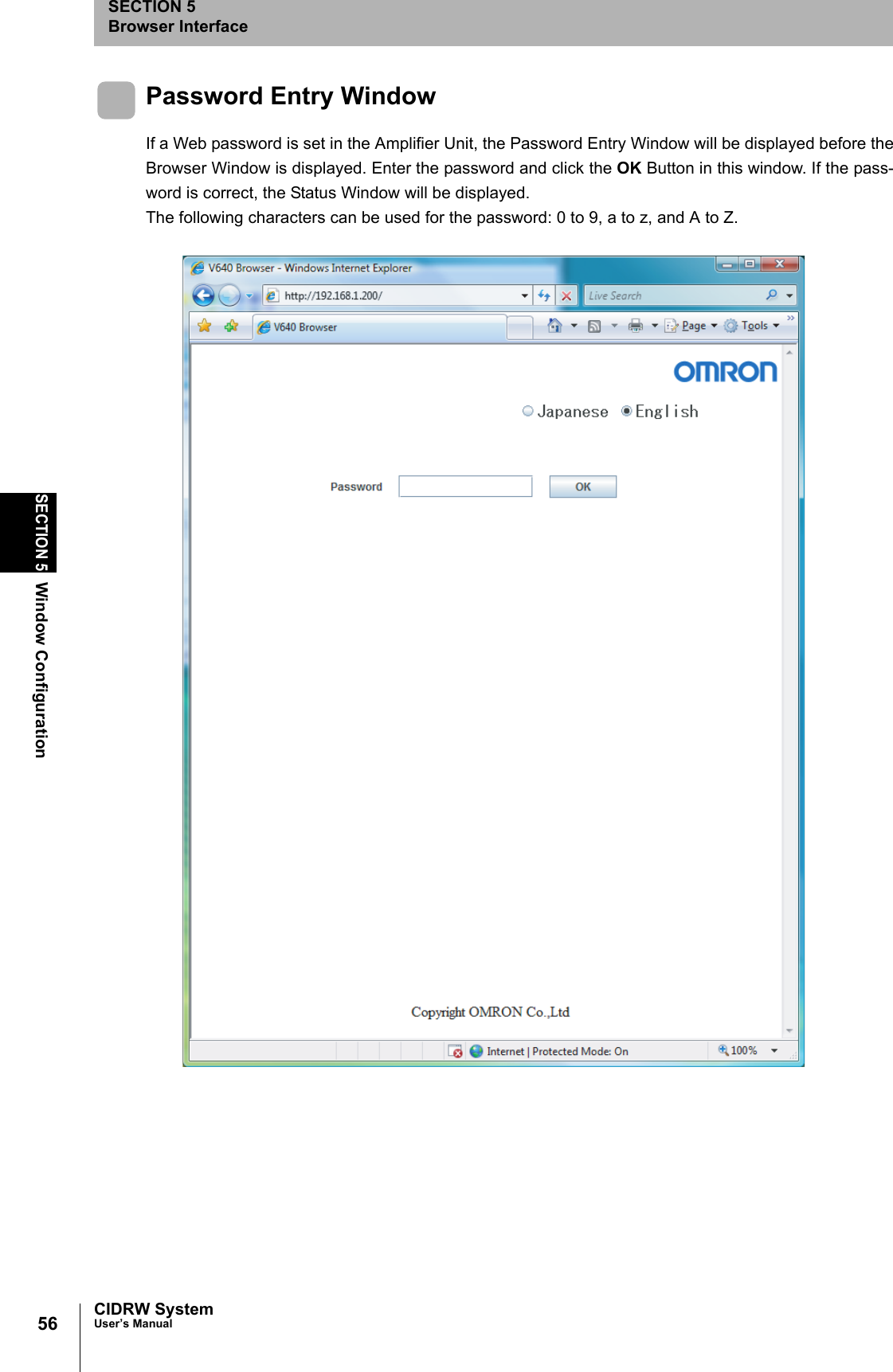
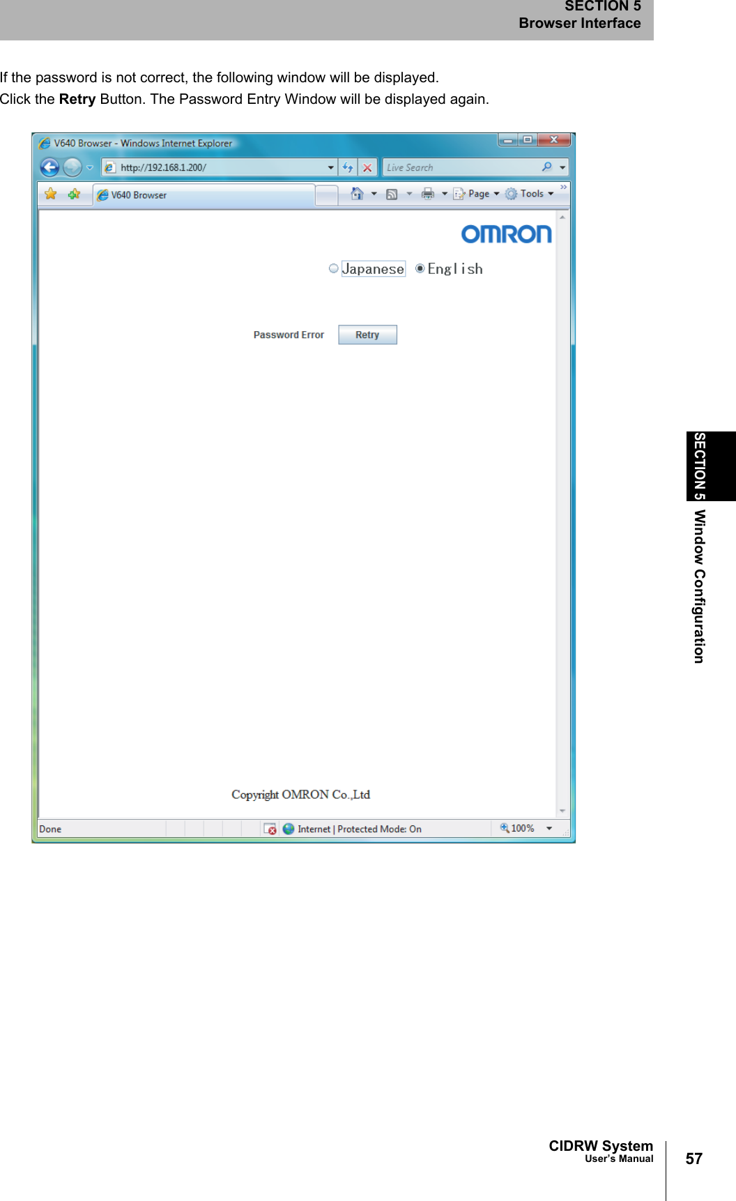
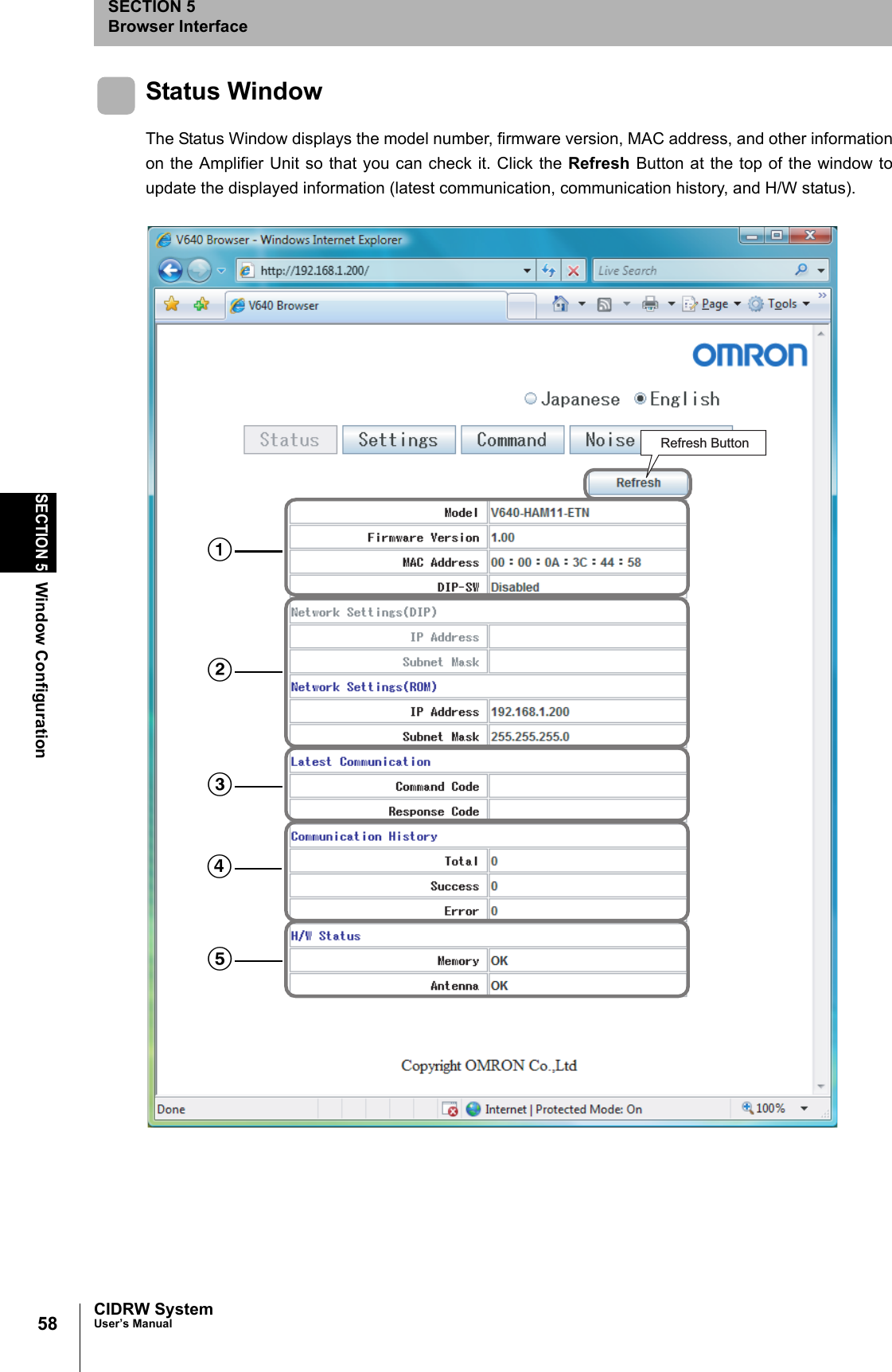
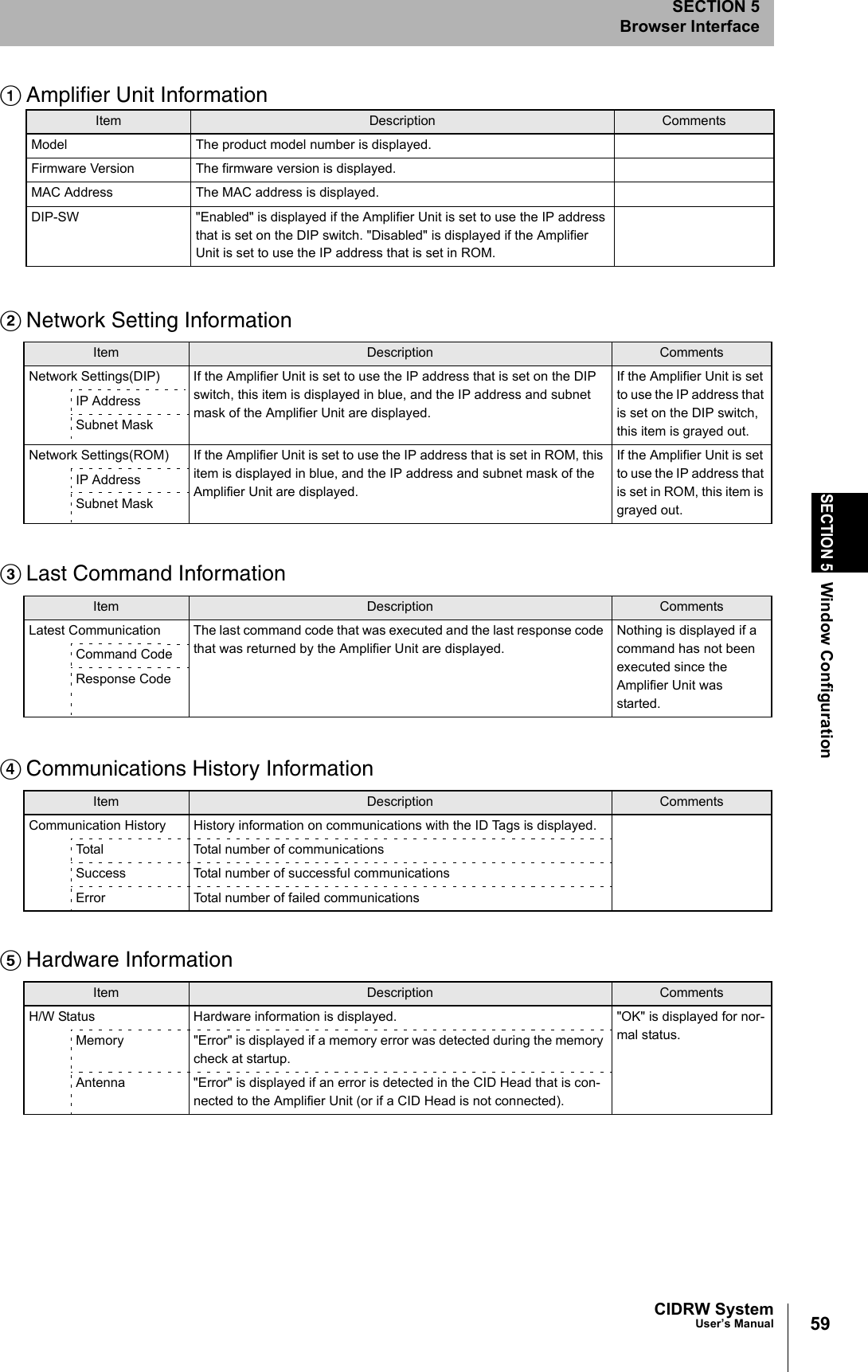
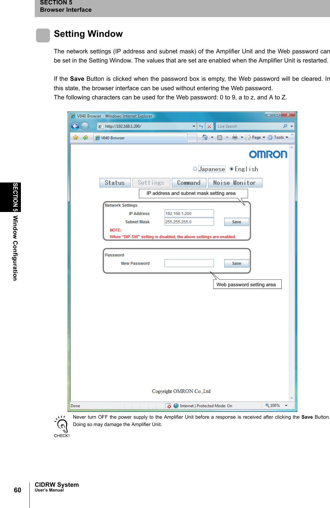
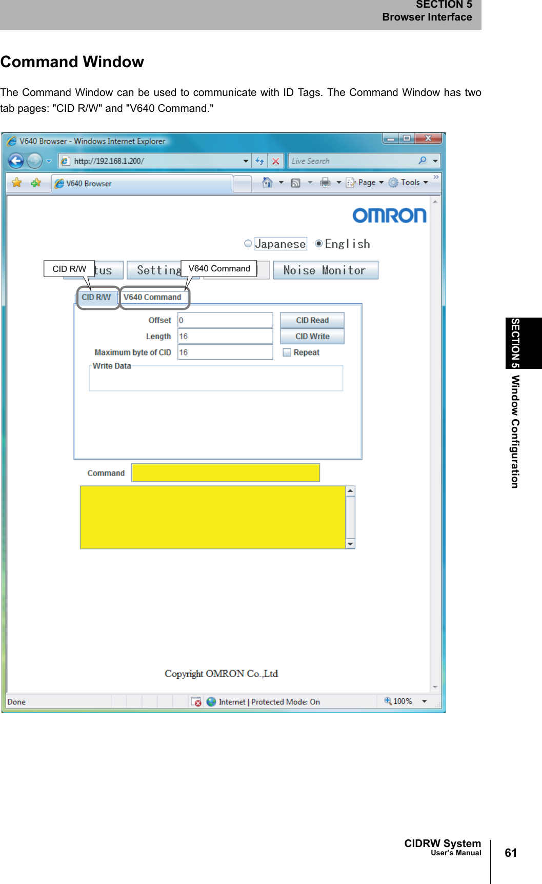
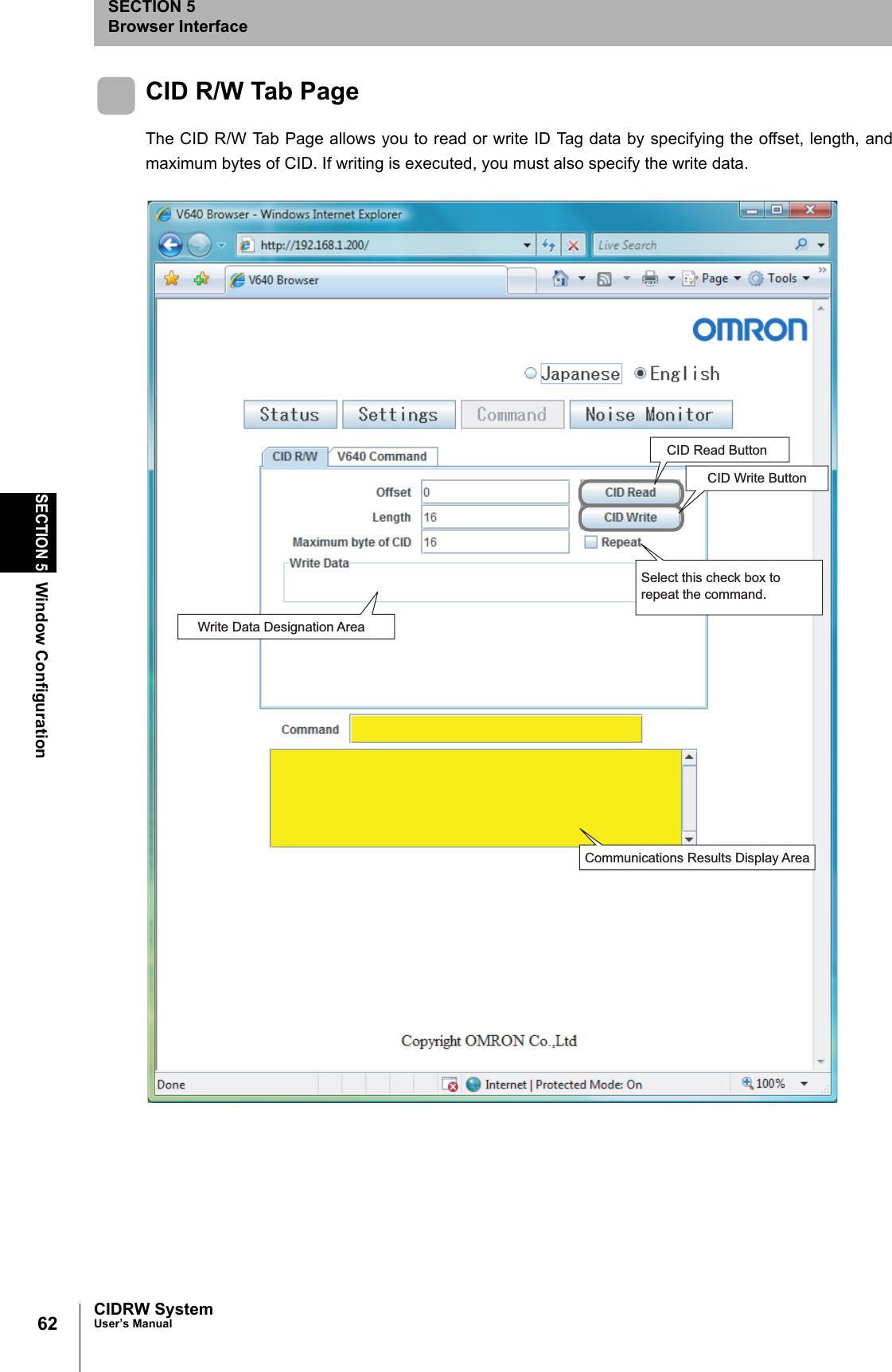
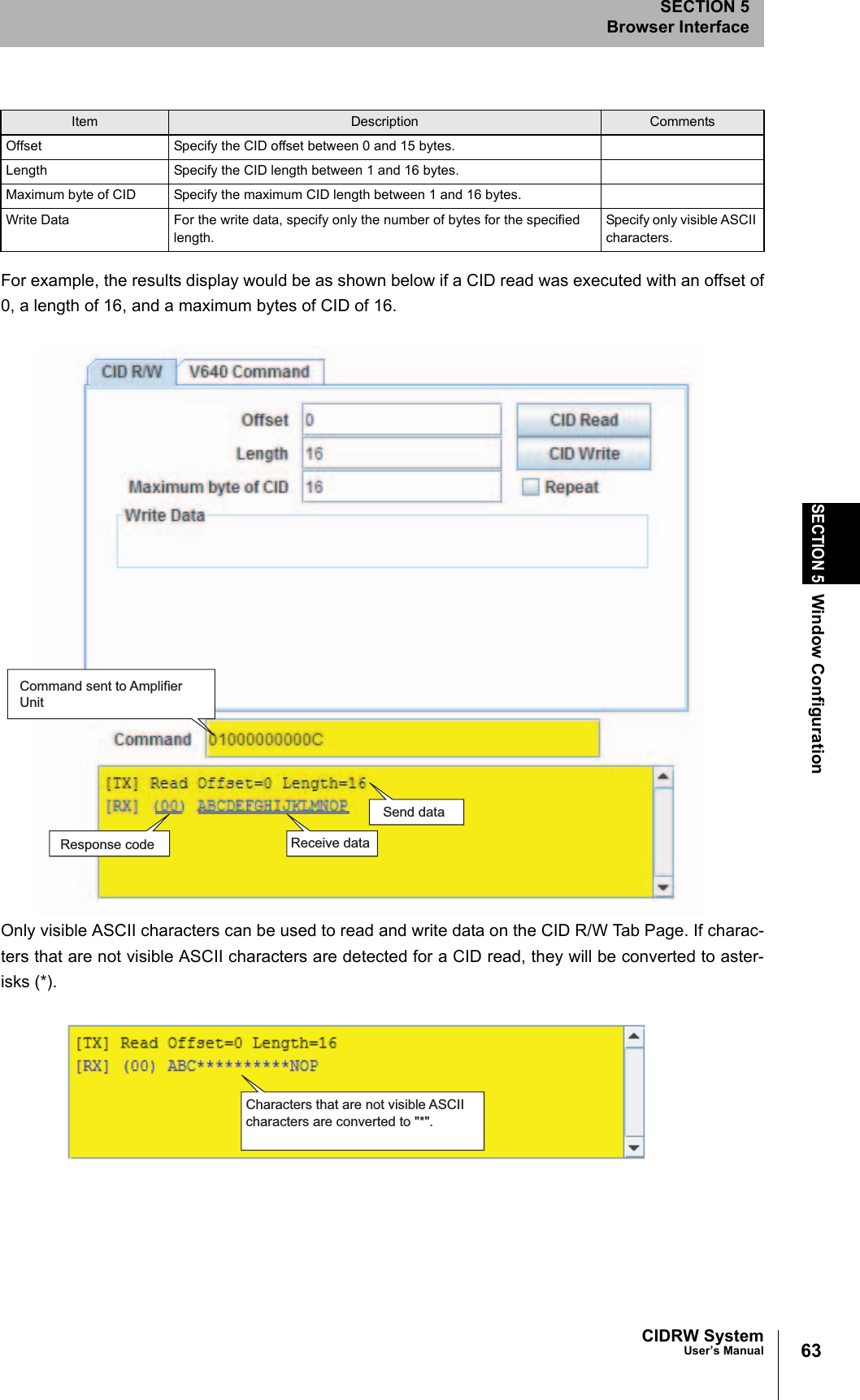
User manual(ETN)