Omron V640HAM11L Carrier ID Reader/Writer (RFID) User Manual Z307 E1 01
Omron Corporation Carrier ID Reader/Writer (RFID) Z307 E1 01
Omron >
Contents
- 1. User manual1(L)
- 2. User manual2(L)
- 3. User manual1(L-ETN)
- 4. User manual2(L-ETN)
User manual1(L)

CIDRW SYSTEM
V640 SERIES
USER'S MANUAL
Cat. No. Z307-E1-01
AMPLIFIER UNITS
V640-HAM11-V3
V640-HAM11-L
CIDRW HEADS
V640-HS61
V640-HS62
CIDRW CONTROLLER
V700-L22
LINK UNIT
V700-L11

Introduction
Thank you for purchasing the V640-series CIDRW System.
Please observe the following points when operating the V640-series CIDRW System:
• Please read and understand the contents of this manual before using the system.
• After reading this manual, store it in a convenient location for easy reference whenever necessary.

ÇÕǹÇ?Ç ëÊ 1 èÕ ëÊ 2 èÕ ëÊ 3 èÕ ëÊ 4 èÕ
INTRODUCTION
SECTION 1 SECTION 2 SECTION 3 SECTION 4 SECTION 5 SECTION 6
Introduction
SECTION 1
SECTION 2
SECTION 3
SECTION 4
SECTION 5
SECTION 6
Table of Contents/Precautions in Using the Products
Product Outline
Installation and Connections/Wiring
Preparing for Communications
Reading from/Writing to ID Tags
Troubleshooting
Appendix
CIDRW System
V640-HAM11-V3 Amplifier Unit
V640-HAM11-L Amplifier Unit
V640-HS61 CIDRW Head
V640-HS62 CIDRW Head
V700-L22 CIDRW Controller
V700-L11 Link Unit
User's Manual

2
INTRODUCTION
Precautions in using the product
CIDRW System
User’s Manual
INTRODUCTION
READ AND UNDERSTAND THIS DOCUMENT
Please read and understand this document before using the products. Please consult your OMRON representative if you
have any questions or comments.
WARRANTY
OMRON’s exclusive warranty is that the products are free from defects in materials and workmanship for a period of one
year (or other period if specified) from date of sale by OMRON.
OMRON MAKES NO WARRANTY OR REPRESENTATION, EXPRESS OR IMPLIED, REGARDING NON-
INFRINGEMENT, MERCHANTABILITY, OR FITNESS FOR PARTICULAR PURPOSE OF THE PRODUCTS. ANY
BUYER OR USER ACKNOWLEDGES THAT THE BUYER OR USER ALONE HAS DETERMINED THAT THE
PRODUCTS WILL SUITABLY MEET THE REQUIREMENTS OF THEIR INTENDED USE. OMRON DISCLAIMS ALL
OTHER WARRANTIES, EXPRESS OR IMPLIED.
LIMITATIONS OF LIABILITY
OMRON SHALL NOT BE RESPONSIBLE FOR SPECIAL, INDIRECT, OR CONSEQUENTIAL DAMAGES, LOSS OF
PROFITS OR COMMERCIAL LOSS IN ANY WAY CONNECTED WITH THE PRODUCTS, WHETHER SUCH CLAIM IS
BASED ON CONTRACT, WARRANTY, NEGLIGENCE, OR STRICT LIABILITY.
In no event shall responsibility of OMRON for any act exceed the individual price of the product on which liability is
asserted.
IN NO EVENT SHALL OMRON BE RESPONSIBLE FOR WARRANTY, REPAIR, OR OTHER CLAIMS REGARDING
THE PRODUCTS UNLESS OMRON’S ANALYSIS CONFIRMS THAT THE PRODUCTS WERE PROPERLY HANDLED,
STORED, INSTALLED, AND MAINTAINED AND NOT SUBJECT TO CONTAMINATION, ABUSE, MISUSE, OR
INAPPROPRIATE MODIFICATION OR REPAIR.
SUITABILITY FOR USE
THE PRODUCTS CONTAINED IN THIS DOCUMENT ARE NOT SAFETY RATED. THEY ARE NOT DESIGNED OR
RATED FOR ENSURING SAFETY OF PERSONS, AND SHOULD NOT BE RELIED UPON AS A SAFETY COMPONENT
OR PROTECTIVE DEVICE FOR SUCH PURPOSES. Please refer to separate catalogs for OMRON's safety rated
products.
OMRON shall not be responsible for conformity with any standards, codes, or regulations that apply to the combination of
products in the customer’s application or use of the product.
At the customer’s request, OMRON will provide applicable third party certification documents identifying ratings and
limitations of use that apply to the products. This information by itself is not sufficient for a complete determination of the
suitability of the products in combination with the end product, machine, system, or other application or use.
The following are some examples of applications for which particular attention must be given. This is not intended to be an
exhaustive list of all possible uses of the products, nor is it intended to imply that the uses listed may be suitable for the
products:
• Outdoor use, uses involving potential chemical contamination or electrical interference, or conditions or uses not
described in this document.
• Nuclear energy control systems, combustion systems, railroad systems, aviation systems, medical equipment,
amusement machines, vehicles, safety equipment, and installations subject to separate industry or government
regulations.
• Systems, machines, and equipment that could present a risk to life or property.
Please know and observe all prohibitions of use applicable to the products.
NEVER USE THE PRODUCTS FOR AN APPLICATION INVOLVING SERIOUS RISK TO LIFE OR PROPERTY
WITHOUT ENSURING THAT THE SYSTEM AS A WHOLE HAS BEEN DESIGNED TO ADDRESS THE RISKS, AND
THAT THE OMRON PRODUCT IS PROPERLY RATED AND INSTALLED FOR THE INTENDED USE WITHIN THE
OVERALL EQUIPMENT OR SYSTEM.

3
CIDRW System
User’s Manual
INTRODUCTION
Precautions in using the product
INTRODUCTION
PERFORMANCE DATA
Performance data given in this document is provided as a guide for the user in determining suitability and does not
constitute a warranty. It may represent the result of OMRON’s test conditions, and the users must correlate it to actual
application requirements. Actual performance is subject to the OMRON Warranty and Limitations of Liability.
CHANGE IN SPECIFICATIONS
Product specifications and accessories may be changed at any time based on improvements and other reasons.
It is our practice to change model numbers when published ratings or features are changed, or when significant
construction changes are made. However, some specifications of the product may be changed without any notice. When
in doubt, special model numbers may be assigned to fix or establish key specifications for your application on your
request. Please consult with your OMRON representative at any time to confirm actual specifications of purchased
products.
DIMENSIONS AND WEIGHTS
Dimensions and weights are nominal and are not to be used for manufacturing purposes, even when tolerances are
shown.
ERRORS AND OMISSIONS
The information in this document has been carefully checked and is believed to be accurate; however, no responsibility is
assumed for clerical, typographical, or proofreading errors, or omissions.
PROGRAMMABLE PRODUCTS
OMRON shall not be responsible for the user’s programming of a programmable product, or any consequence thereof.
COPYRIGHT AND COPY PERMISSION
This document shall not be copied for sales or promotions without permission.
This document is protected by copyright and is intended solely for use in conjunction with the product. Please notify us
before copying or reproducing this document in any manner, for any other purpose. If copying or transmitting this
document to another, please copy or transmit it in its entirety.

4
INTRODUCTION
Precautions in using the product
CIDRW System
User’s Manual
INTRODUCTION
To Users of the V700-L21 CIDRW Controller
The V700-L22 CIDRW Controller complies with the 2003 edition of the SEMI E99 standard. The V700-
L21 CIDRW Controller cannot simply be replaced with the V700-L22. To replace the V700-L21 with the V700-L22, the
control programming for the CIDRW Controller must be updated as described in this manual.
■Main Differences from the V700-L21
• Added Attributes
The CIDRW attributes defined as CarrierIDOffset and CarrierIDlength in the 2003 edition of the SEMI
E99 standard have been added. With the V700-L22, the user can now specify as attributes the position
of the MID in the ID Tag, and the data length.
Refer to Support Attributes p.152.
• Changed Message Specifications
The 2003 edition of SEMI E99 adds a format definition for the data item MID in the message specifica-
tions. The specifications of the data item MID have changed in the V700-L22.
Refer to Message Specifications p.70.
• Added Data Area Access Function
A function for specifying ID Tag data area access destinations as offset addresses has been added to
the V700-L22. The V700-L21 divides the data area into 8-byte units called segments, and reads and
writes data to each segment. Besides this, the V700-L22 also allows you to specify offset addresses
relative to the first address in the ID Tag data area, so that data can be read and written in units of one
byte.
Refer to Message Specifications p.70.
• Replacing the V700-L21 with theV700-L22
The following settings are required to replace the V700-L21 with the V700-L22.
(1) Set the CarrierIDOffset and CarrierIDlength attributes.
Set CarrierIDOffset to 0 and set CarrierIDlength to the data length of the data item MID specified
by the ID write request (S18F11). If there is a mismatch between the CarrierIDlength attribute and
the MID length in the ID write request (S18F11), a CE (communications error) occurs, and no data
is written.
(2) Change the MID to data consisting of displayable ASCII characters only.
With the V700-L22, data that includes undisplayable ASCII characters cannot be read with an ID
read request (S18F9); an EE (execution error) occurs. Data including undisplayable ASCII charac-
ters in the MID cannot be specified with an ID write request (S18F11).
With the V700-L21, the MID to be read or written is assigned to an area fixed at 16 bytes. If the specified data length in the ID
write request (S18F11) is less than 16 bytes, NUL characters are added in internal processing to make the total 16 bytes. In
contrast, with the V700-L22, the accessible MID data occupies only the area specified by the CarrierIDOffset and
CarrierIDlength attributes. Data can be read or written only in the area specified by the attributes.

5
CIDRW System
User’s Manual
INTRODUCTION
Precautions in using the product
INTRODUCTION
Applicable Standards
The CIDRW System complies with the following international regulations and standards.
1. USA
FCC NOTICE
This device complies with part 15 of the FCC Rules. Operation is subject to the following two conditions:
(1) This device may not cause harmful interference.
(2) This device must accept any interference received, including interference that may cause undesired opera-
tion.
FCC WARNING
Changes or modifications not expressly approved by the party responsible for compliance could void the user's
authority to operate the equipment.
Do not remove the ferrite core (TDK-EPC Type ZCAT2749-0430C:V640-HS62) installed on the cables to suppress RF
interference.
FCC Part15 subpart B
NOTICE
This equipment has been tested and found to comply with the limits for a Class A digital device, pursuant to part15 of
the FCC Rules. These limits are designed to provide reasonable protection against harmful interference when the
equipment is operated in a commercial environment.
This equipment generates, uses and can radiate radio frequency energy and, if not installed and used in accordance
with the instructions, may cause harmful interference to radio communications. Operation of this equipment in a
residential area is likely to cause harmful interference in which case the user will be required to correct the interference
at his own expense.
CAUTION
This device must be professionally installed.
2. Canada
This device complies with RSS-Gen of IC (Industry Canada) Rules.
Operation is subject to the following two conditions: (1) this device may not cause harmful interference, and (2)
this device must accept any interference received, including interference that may cause undesired operation.
ICES-003
This class A digital apparatus complies with Canadian ICES-003.
Cet appareil numerique de la classe A est conforme a la norme NMB-003 du Canada.
CIDRW Amplifier Unit CIDRW Head
FCC Part 15 Subpart C
FCC ID: E4EV640HAM11
V640-HAM11-V3 V640-HS61
FCC Part 15 Subpart C
FCC ID: E4EV640HAM11L
V640-HAM11-L V640-HS62
CIDRW Amplifier Unit CIDRW Head
IC ID: 850J-V64HAM11 V640-HAM11-V3 V640-HS61
IC ID: 850J-V64HM11L V640-HAM11-L V640-HS62

6
INTRODUCTION
Precautions in using the product
CIDRW System
User’s Manual
INTRODUCTION
Applicable SEMI Standards
This CIDRW system complies with the following standards.
• SEMI E99 THE CARRIER ID READER/WRITER FUNCTIONAL STANDARD
• SEMI E5 EQUIPMENT COMMUNICATION STANDARD 2 MESSAGE CONTENT (SECS II)
• SEMI E4 EQUIPMENT COMMUNICATION STANDARD 1 MESSAGE TRANSFER (SECS I)
SEMI is the acronym for Semiconductor Equipment and Materials International.
SECS is the acronym for SEMI Equipment Communication Standard.

7
CIDRW System
User’s Manual
INTRODUCTION
Precautions in using the product
INTRODUCTION
● Definition of Precautionary Information
The following notation and alert symbols are used in this User's Manual to provide precautions required to
ensure safe usage of a V640-series CIDRW System. The safety precautions that are provided are extremely
important to safety. Always read and heed the information provided in all safety precautions.
The following signal words are used in this manual.
● Meanings of Alert Symbols
● Alert Statements in this Manual
Please observe the following precautions for safe use of the products.
• Do not allow water to enter or insert wires through gaps in the case. This could cause fire or electric shock.
• In the event of a malfunction, stop using the product immediately, turn OFF the power, and consult your
OMRON dealer.
• Dispose of this product as industrial waste.
• Do not remove the CIDRW Head from the Amplifier Unit while power is being supplied.
Confirm the effects of radio waves on medical devices. The following guideline is from JAISA (Japan
Automatic Identification Systems Association).
Indicates a potentially hazardous situation which, if not avoided, will result in minor or
moderate injury, or may result in serious injury or death. Additionally there may be signif-
icant property damage.
Prohibition
Indicates general prohibitions for which there is no specific symbol.
The product is not designed or rated for ensuring the safety of persons.
Do not use it for such purposes.
This product is a reader-writer that uses radio waves for RFID equipment. The application
and location of this product may affect medical devices. The following precaution must be
observed in the application of the product to minimize the effects on medical devices.
Any person with an implanted medical device must keep the area where the device is
implanted at least 22 cm away from the antenna of a stationary or modular RFID device.
Safety Precautions
WARNING
WARNING
Precautions for Safe Use

8
INTRODUCTION
Precautions in using the product
CIDRW System
User’s Manual
INTRODUCTION
Please observe the following precautions to prevent failure to operate, malfunctions, or undesirable effects on
product performance.
■Installation Site
Install the product at a location where:
• It is not exposed to direct sunlight.
• It is not exposed to corrosive gases, dust, metal chips, or salt.
• The working temperature is within the range stipulated in the specifications.
• There are no sudden variations in temperature (no condensation).
• The relative humidity is within the range stipulated in the specifications.
• No vibration or shock exceeding the values stipulated in the specifications is transmitted directly to
the body of the product.
• It is not subject to splashing water, oil, or chemical substances.
■Mounting
• This product communicates with ID Tags using the 134 kHz frequency band. Some transceivers,
motors, monitoring equipment, and power supplies (power supply ICs) generate electrical waves
(noise) that interfere with communications with ID Tags. If you are using the product in the vicinity of
any of these devices, check the effect on communications in advance.
• In order to minimize the effects of noise, ground nearby metal bodies with a grounding resistance not
exceeding 100 ohms.
• When mounting Amplifier Units, tighten the screws with a torque no greater than 1.2 N·m.
• When mounting CIDRW Heads, tighten the screws with a torque no greater than 0.6 N·m.
• When multiple CIDRW Heads are mounted next to each other, communications performance could
be impaired by mutual interference. Read and follow the information in this manual on mutual inter-
ference when installing multiple Heads.
Refer to page 122.
Precautions for Correct Use

9
CIDRW System
User’s Manual
INTRODUCTION
Precautions in using the product
INTRODUCTION
■Power and Ground Cables
• Use the power supply voltage specified in this manual.
• Ensure correct polarity when connecting to the +/- power supply terminals.
• The ground terminals must be connected to a ground with a grounding resistance not exceeding 100
ohms.
• When using the CIDRW System in Europe, the connecting cable between the CIDRW and the DC
power supply must be 3 m or less.
■Wiring Work
• Always turn the power OFF before starting wiring work or connecting/disconnecting cables.
• Do not run high-voltage lines and power lines though the same conduit.
• To prevent damage by static electricity, wear a wrist strap or equivalent, and take measures to pre-
vent charging, before touching terminal components or parts inside connectors.
■Screw Locking Adhesive
• Screw locking adhesive (screw lock) may cause deterioration and cracking of resin parts; do not use
it for screws in resin parts or anywhere where resin washers are used.
■Cleaning
• Use standard grade alcohol.
• Do not use organic solvents such as thinner or benzene.
■Communications with the Host Device
Communicate with the host device only after confirming that the CIDRW Controller has started. Also,
unstable signals may occur at the host interface when the CIDRW Controller is started. When initializ-
ing operation, clear the reception buffer at the host device or take other suitable methods to clear
unwanted signals.
■Startup Precaution
Never turn OFF the power supply while the CIDRW Controller is starting, including when power is
turned ON, when the mode is changed, or when the CIDRW Controller is being reset. Doing so may
damage the CIDRW Controller.
10
INTRODUCTION
Precautions in using the product
CIDRW System
User’s Manual
INTRODUCTION
Reading this Manual
Visual Aids
Indicates an explanation of a point that must be observed to ensure that the product is capable of its proper functions and perfor-
mance. Read this information carefully and follow the cautions. If the product is used incorrectly, data or the equipment itself
could be destroyed.
Indicates summaries of points of particular importance relating to product performance, e.g., points to note during operation and
advice on how to use the product.
Indicates the number of a page where related information can be found.
Indicates information for reference when you encounter a problem.
Indicator Status
The following symbols are used to show the status of the indicators on the CIDRW Controller and Amplifier
Units.
OFF
Flashing
ON

11
CIDRW System
User’s Manual
INTRODUCTION
Table of Contents
INTRODUCTION
Table of Contents
Table of Contents
Introduction 2
To Users of the V700-L21 CIDRW Controller 4
Applicable Standards 5
Applicable SEMI Standards 5
Safety Precautions 6
Precautions for Safe Use 6
Precautions for Correct Use 7
Reading this Manual 9
Table of Contents 11
SECTION 1 Product Outline 13
What Is a CIDRW System? 14
Features 15
System Configuration 16
Component Names and Functions 17
Flowchart for Getting Started 21
SECTION 2 Installation and Connections/Wiring 25
Installation 26
Connections and Wiring 31
SECTION 3 Preparing for Communications 47
Setting the Communications Conditions for the CIDRW Controller 48
Setting the Communications Conditions for Amplifier Units 61
Setting the Communications Conditions for Link Units 63
Communications Test 64
SECTION 4 Reading from/Writing to ID Tags 69
When SECS Is Used 70
When SECS Is Not Used 81

12
INTRODUCTION
Table of Contents
CIDRW System
User’s Manual
INTRODUCTION
Table of Contents
SECTION 5 Troubleshooting 95
When SECS Is Used 96
When SECS Is Not Used 102
SECTION 6 Appendix 109
Specifications and Dimensions 110
System Configuration Examples 115
Characteristic Data According to Conditions of Use 117
ID Tag Memory Maps 147
Regular Inspection 148
SECS Protocol Specifications 149
ASCII Code Table 154
Protective Construction 155
Revision History 159

SECTION 1
Product Outline
13
CIDRW System
User’s Manual
SECTION 1
Product Outline
What Is a CIDRW System? 14
Features 15
System Configuration 16
Component Names and Functions 17
Flowchart for Getting Started 21
14
SECTION 1
What Is a CIDRW System?
CIDRW System
User’s Manual
SECTION 1
Product Outline
What Is a CIDRW System?
The CIDRW system writes data to, and reads data from, the carrier IDs (ID Tags) mounted on the carriers
(FOUP) in semiconductor manufacturing processes without contacting these ID Tags. CIDRW is the
abbreviation of Carrier ID Reader/Writer and this abbreviation is used throughout this manual.
Reading and writing information such as models, process instructions, lots, and inspection results to and from
ID Tags makes it possible to manage work instruction information from a host device.
Example: Management of information in semiconductor and wafer manufacturing processes
ID Tag
(holder is separate)
CIDRW Head
Reading and writing
information
• Model information
• Process instruction
information
• Completion
information
• Lot information
• Inspection results
Etc.
Host
Amplifier Unit
CIDRW Controller
15
CIDRW System
User’s Manual
SECTION 1
Features
SECTION 1
Product Outline
Features
■CIDRW Systems That Conform to SEMI Standards (SEMI E99, E5, E4)
List of Applicable Standards
• SEMI E99 THE CARRIER ID READER/WRITER FUNCTIONAL STANDARD
• SEMI E5 EQUIPMENT COMMUNICATION STANDARD 2 MESSAGE CONTENT (SECS II)
• SEMI E4 EQUIPMENT COMMUNICATION STANDARD 1 MESSAGE TRANSFER (SECS I)
SEMI is the acronym for Semiconductor Equipment and Materials International.
SECS is the acronym for SEMI Equipment Communications Standard.
The V640-HAM11-V3 or V640-HAM11-L will automatically detect the model and read/write data for RI-TRP-
DR2B and RI-TRP--WR2B ID Tags manufacturer by Texas Instruments.
Host
SECS I/II
CIDRW Controller
V700-L22
Amplifier Unit
V640-HAM11-V3
CIDRW Head
V640-HS61
ID Tag
RI-TRP-DR2B
RI-TRP-WR2B
(Made by Texas
Instruments)
CIDRW System Conforming to SEMI Standards
RS-232C RS-232C
• V640-HAM11-V3
• V640-HAM11-L
Host
SECS I/II
CIDRW Controller
V700-L22
Amplifier Unit
V640-HAM11-L
CIDRW Head
V640-HS62
ID Tag
RI-TRP-DR2B
RI-TRP-WR2B
(Made by Texas
Instruments)
CIDRW System Conforming to SEMI Standards
RS-232C RS-232C
The V640-HS61 CIDRW Head can be connected to V640-HAM11-V3 Amplifier Units to communi-
cate with ID Tags.
The V640-HS62 CIDRW Head can be connected to V640-HAM11-L Amplifier Units to communicate
long-distance with ID Tags. The functions of the V640-HAM11-L Amplifier Unit are the same as the
functions of the V640-HAM11-V3 Amplifier Unit.
16
SECTION 1
System Configuration
CIDRW System
User’s Manual
SECTION 1
Product Outline
System Configuration
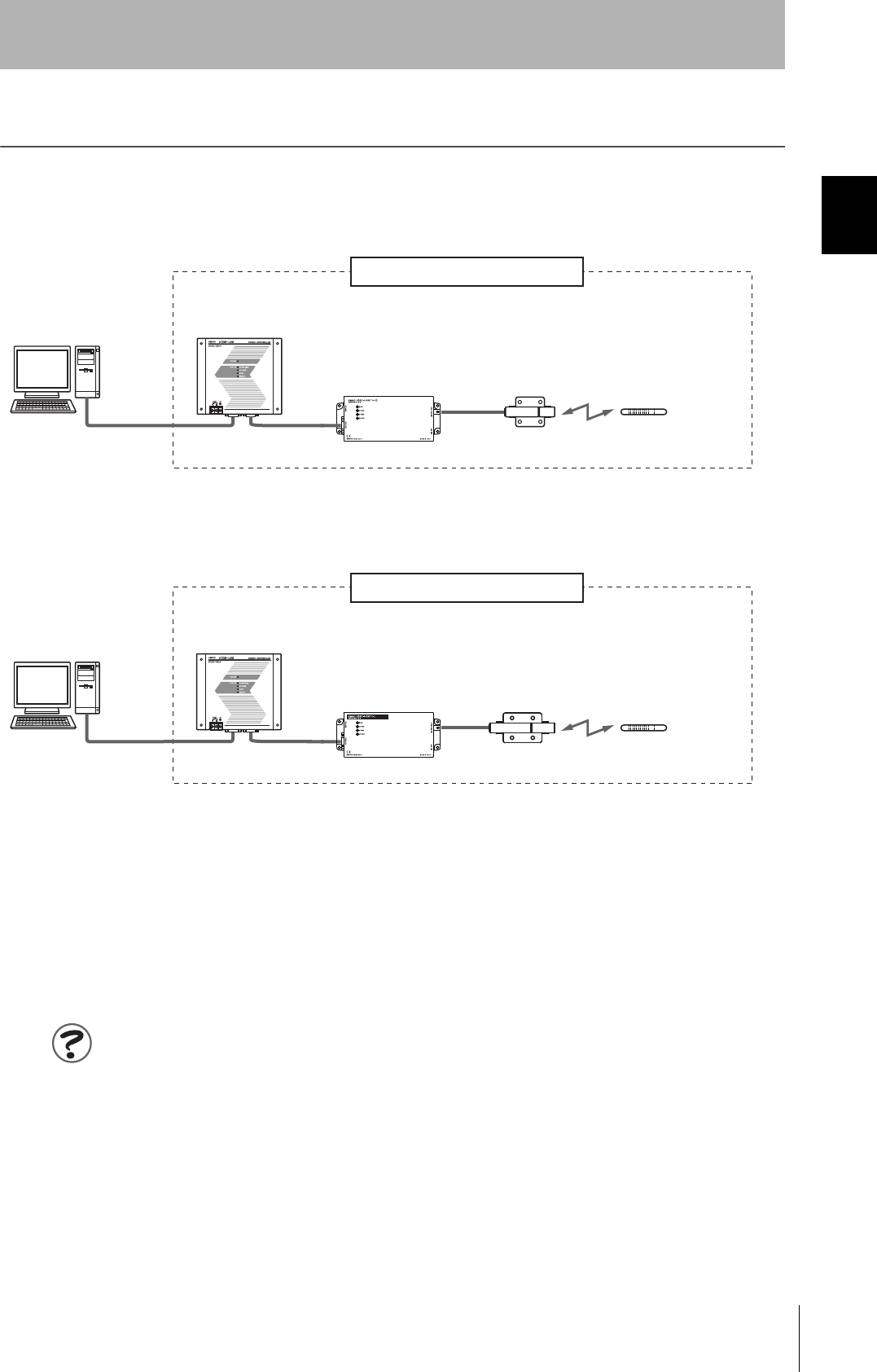
When SECS Is Used
Communications with the host device is possible using the SECS protocol.
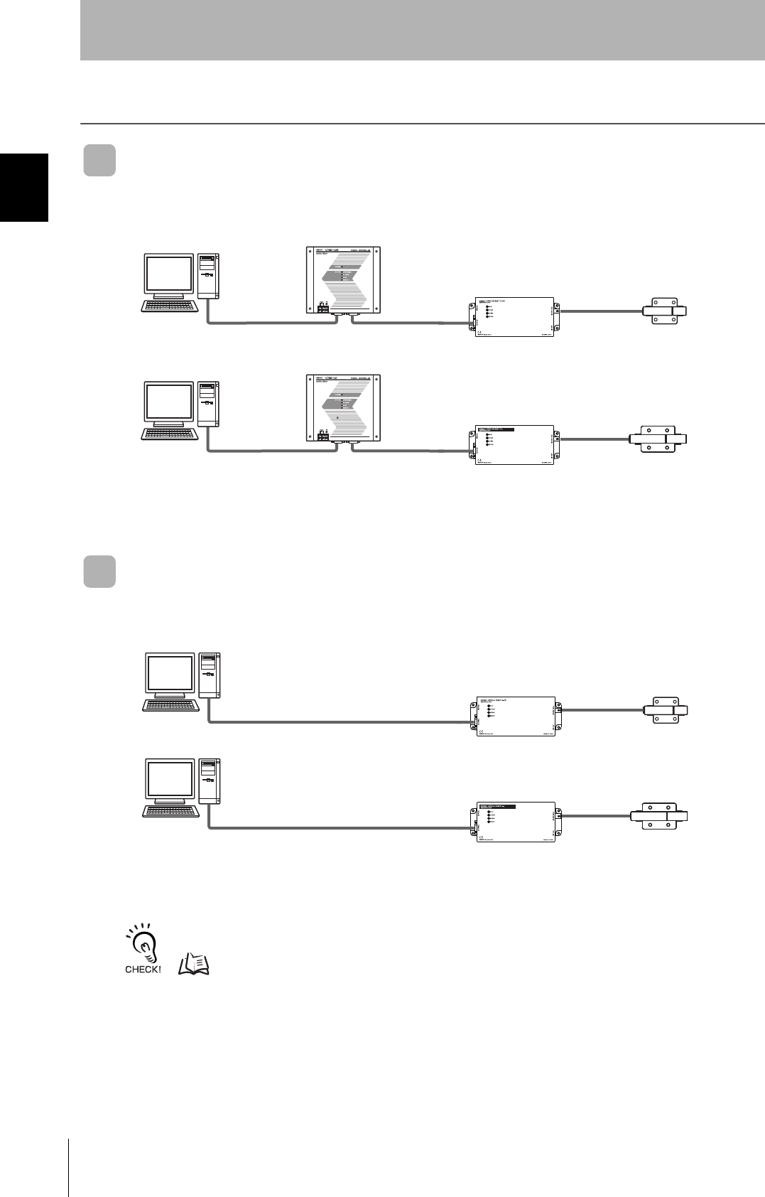
When SECS Is Not Used
Communications with the host device follow the OMRON proprietary protocol.
The Amplifier Units are connected directly to the host device without using a CIDRW Controller.
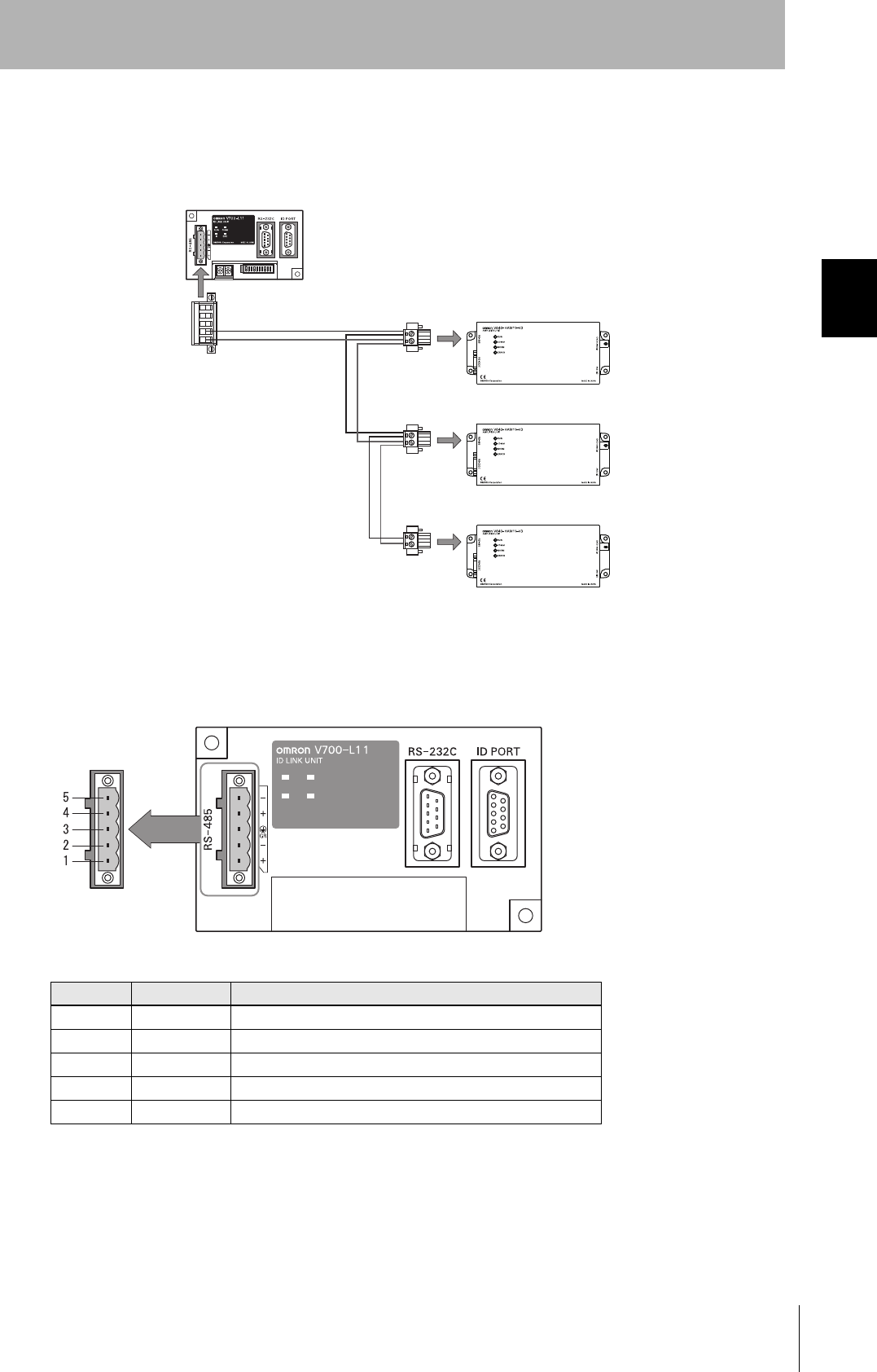
Refer to the following page for connection examples for up to 31 Amplifier Units or for connection examples for using
the V700-L11 Link Unit.
page 115
Using Link Units (V700-L11) to make connections makes it possible to remove and replace just the rele-
vant Amplifier Unit while leaving the power to the CIDRW system on in the event of a failure or during
maintenance.
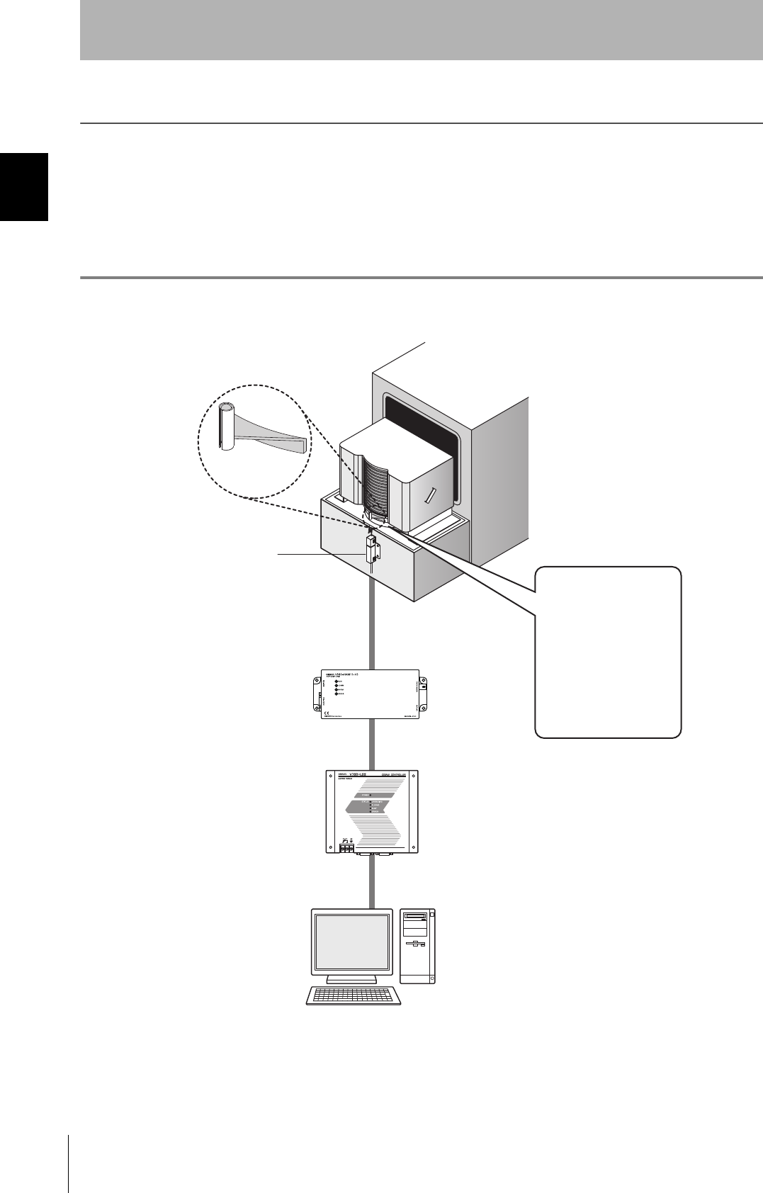
The CIDRW Heads are the
antennas for reading the
carrier IDs from the ID Tags
and writing the carrier IDs.
The Amplifier Units con-
trol the CIDRW Heads.
This is a host computer,
equipment controller, etc.
CIDRW Head
V640-HS61
Amplifier Unit
V640-HAM11-V3
CIDRW Controller
V700-L22
Host
Multiple Amplifier Units
are controlled in
response to commands
(SECS) from the host
device.
RS-232C
SECS I/II RS-232C
CIDRW Head
V640-HS62
Amplifier Unit
V640-HAM11-L
CIDRW Controller
V700-L22
Host
RS-232C
SECS I/II RS-232C
The CIDRW Heads are the
antennas for reading the
carrier IDs from the ID Tags
and writing the carrier IDs.
The Amplifier Units con-
trol the CIDRW Heads.
This is a host computer,
equipment controller, etc.
CIDRW Head
V640-HS61
Amplifier Unit
V640-HAM11-V3
Host
RS-232C
OMRON proprietary protocol
CIDRW Head
V640-HS62
Amplifier Unit
V640-HAM11-L
Host
RS-232C
OMRON proprietary protocol
17
CIDRW System
User’s Manual
SECTION 1
Component Names and Functions
SECTION 1
Product Outline
Component Names and Functions
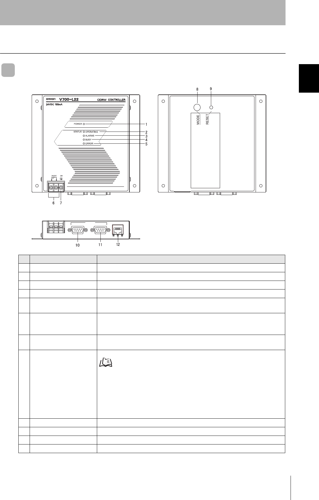
V700-L22 CIDRW Controller
No. Name Function
1 Power indicator (green) An indicator that indicates whether the power is ON or OFF. Lit while the power is ON.
2 OPERATING indicator (green) Lit while the CIDRW system status model is operating.
3 ALARMS indicator (green) Lit when the status in "Alarm Status" of the CIDRW system is Alarm (1).
4 BUSY indicator (green) Lit when the status in "Operational Status" of the CIDRW system is BUSY.
5 ERROR indicator (red) When a processing error is detected (when SSACK is other than NO), this indicator is lit
for 50 ms.
6 24 VDC power supply termi-
nals
(with cover)
Connect to the 24 VDC power supply.
7 Frame ground terminal
(with cover)
The grounding wire is connected here. (Ground to 100 Ω or less)
8 MODE switch Used to select the mode of operation.
Refer to page 48.
0: Normal Operation mode. When mounting the Controller, set the switch to this posi-
tion.
3: Setting mode, selected to set information such as the communications conditions.
When the switch on the bottom face of the Controller cannot be accessed, the opera-
tion mode can be changed from the host device while the switch is left at the 0 set-
ting.
1 to 2, 4 to 7: Setting prohibited
9 RESET switch Restarts the CIDRW Controller.
10 SECS port Port for connecting the host device. Conforms to SECS I/II.
11 ID port An Amplifier Unit or Link Unit is connected here.
12 Maintenance port (with cover) Not used. Do not remove the cover.
RS-232C
SECS ID MAINTENANNCE
18
SECTION 1
Component Names and Functions
CIDRW System
User’s Manual
SECTION 1
Product Outline
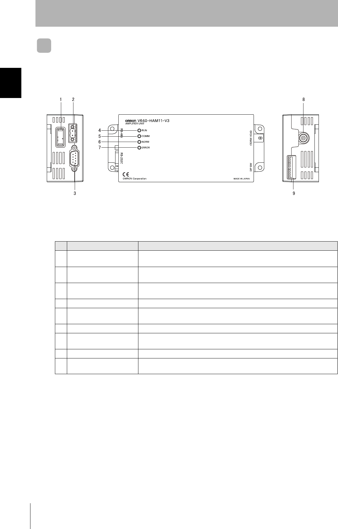
V640-HAM11-V3 and V640-HAM11-L Amplifier Units
No. Name Function
1 Dedicated power supply con-
nector
Connect to the 24 VDC power supply.
2 RS-485 port When using multiple CIDRW Heads, connect this to the RS-485 port of another Amplifier
Unit or to the multi-connection port of a Link Unit.
3 RS-232C port Connected to a CIDRW Controller or a host device.
Uses the OMRON proprietary communications protocol.
4 RUN indicator (green) Turns ON when the Amplifier Unit is in normal operation.
5 COMM indicator (yellow) Turns ON during communications with the host device or during communications with an
ID Tag.
6 NORM indicator (green) Turns ON when the communications finish with no error.
7 ERROR indicator (red) Turns ON when an error occurs during communications with the host device, or during
communications with an ID Tag.
8 CIDRW Head connection port A CIDRW Head is connected here.
9 Setting DIP switches Used to set the node number, the communications conditions, and the RS-485 terminal
resistance.
19
CIDRW System
User’s Manual
SECTION 1
Component Names and Functions
SECTION 1
Product Outline
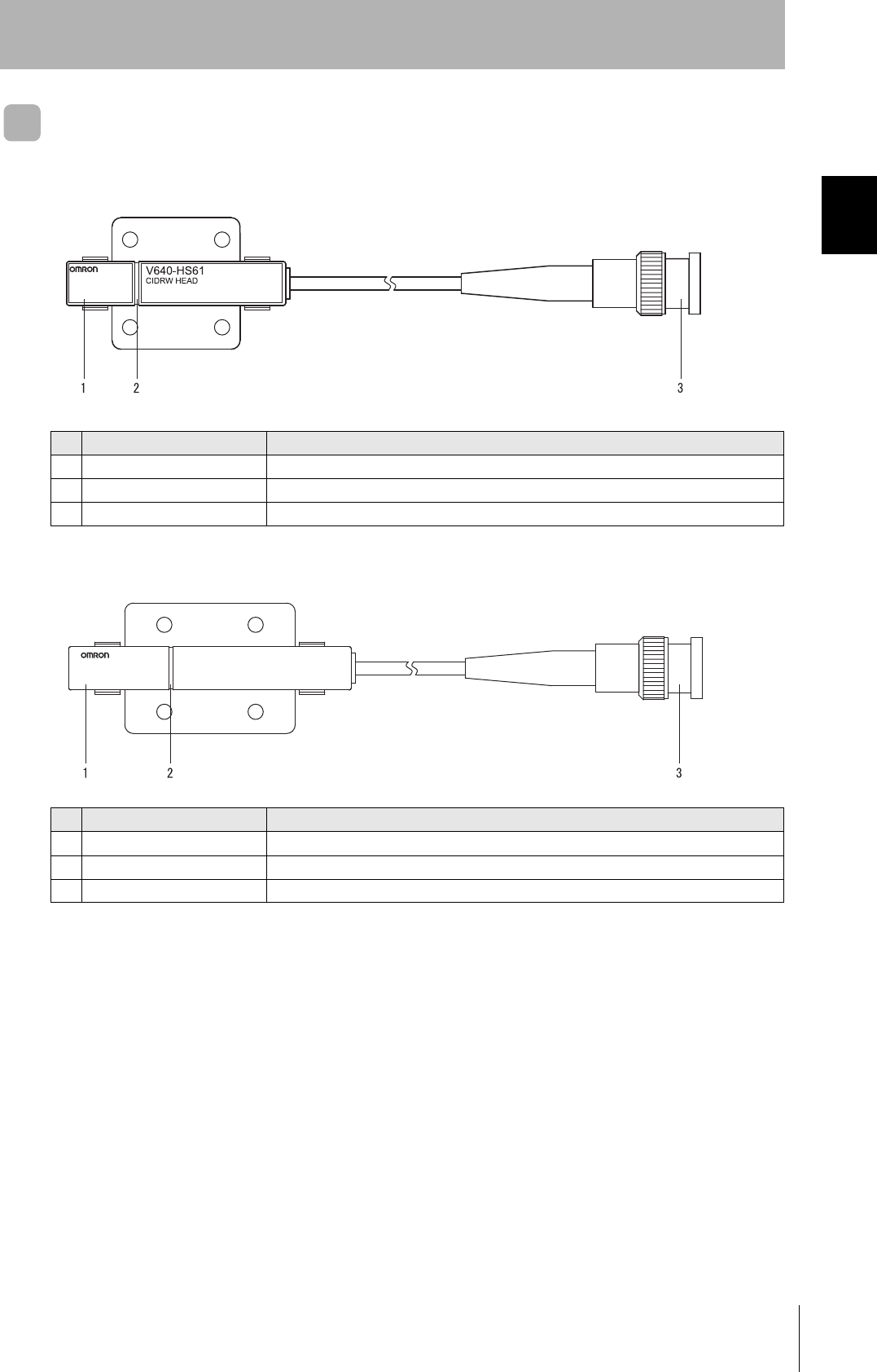
V640-HS61 and V640-HS62 CIDRW Heads
■V640-HS61
■V640-HS62
No. Name Function
1 Antenna Used to communicate with ID Tags.
2 Antenna center This is the center of the communications area.
3 Connector Connect to an Amplifier Unit.
No. Name Function
1 Antenna Used to communicate with ID Tags.
2 Antenna center This is the center of the communications area.
3 Connector Connect to an Amplifier Unit.
V640-HS62
CIDRW HEAD
MADE IN JAPAN
20
SECTION 1
Component Names and Functions
CIDRW System
User’s Manual
SECTION 1
Product Outline
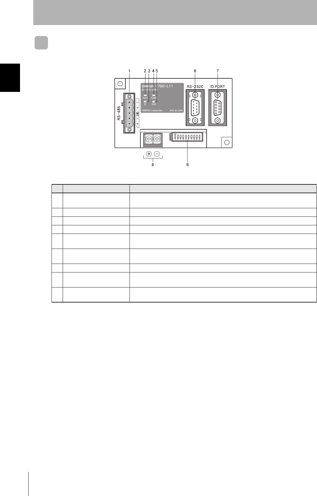
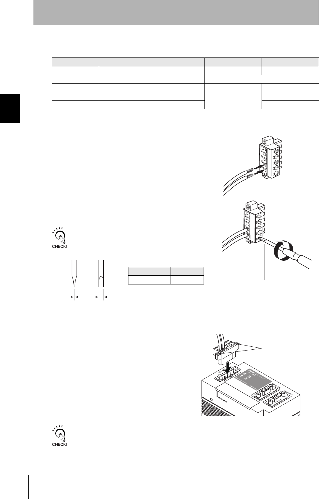
V700-L11 Link Unit
No. Name Function
1 Multi-connection port
(RS-485)
This is the port that connects to the Amplifier Units when multiple CIDRW Heads are
connected to a CIDRW Controller. The GR (frame ground) terminal is also at this port.
2 RUN indicator (green) Turns ON while the Link Unit is in normal operation.
3 ID indicator (green) Not used
4 COMM indicator (green) Turns ON during data communications with the host device.
5 ERR indicator (red) Turns ON when an error occurs during data communications with the host device or
Head.
6 Host device connection port
(RS-232C)
This is a port for connecting to the CIDRW Controller via an RS-232C interface. A dust
cover is fitted on shipment from the factory. Remove this cover before using the port.
7 ID connection port Not used
8 24 V power supply terminals
(inside the cover)
Connect to the 24 VDC power supply.
9 Setting DIP switches
(inside the cover)
Used to set the equipment number, the communications conditions, and the RS-485 ter-
minal resistance.
21
CIDRW System
User’s Manual
SECTION 1
Flowchart for Getting Started
SECTION 1
Product Outline
Flowchart for Getting Started
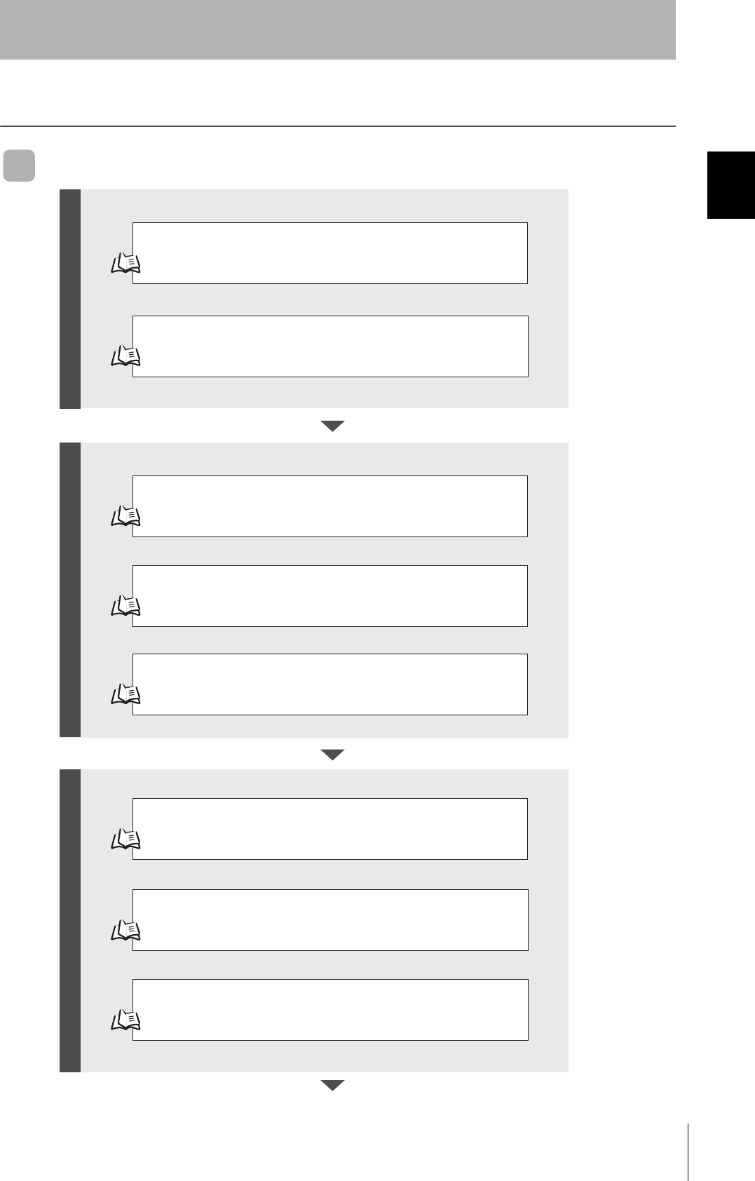
When SECS Is Used
Refer to page 26.
Refer to page 31.
Refer to page 48.
Refer to page 61.
Refer to page 64.
Refer to page 66.
Installation
Connection and Wiring
Setting the Communications Conditions for the CIDRW Controller
Setting the Communications Conditions for Amplifier Units
Refer to page 63.
Setting the Communications Conditions for Link Units
Test for Communications with the Host Device
ID Tag <-> CIDRW System Communications Test
Check the Surrounding Environment
Refer to page 28.
Preparation for CommunicationsTrial Operation Installation and Connections
22
SECTION 1
Flowchart for Getting Started
CIDRW System
User’s Manual
SECTION 1
Product Outline
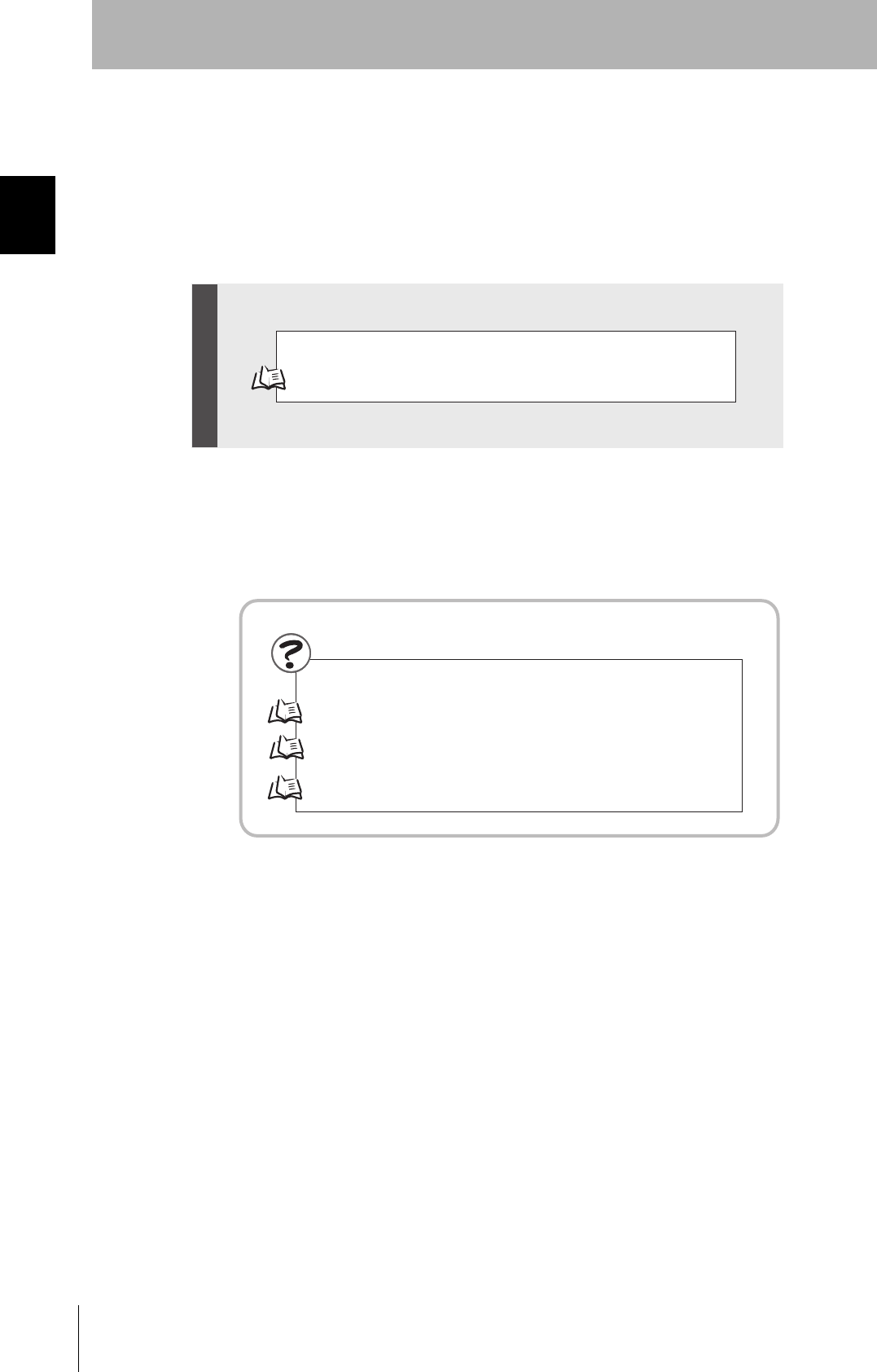
Refer to page 70.
Refer to page 96. List of Error Messages
Refer to page 96. Controller Indicators
Refer to page 97. Operation Check Flowchart
When SECS Is Used
When SECS Is Used
When you Encounter a Problem...
Communications
23
CIDRW System
User’s Manual
SECTION 1
Flowchart for Getting Started
SECTION 1
Product Outline
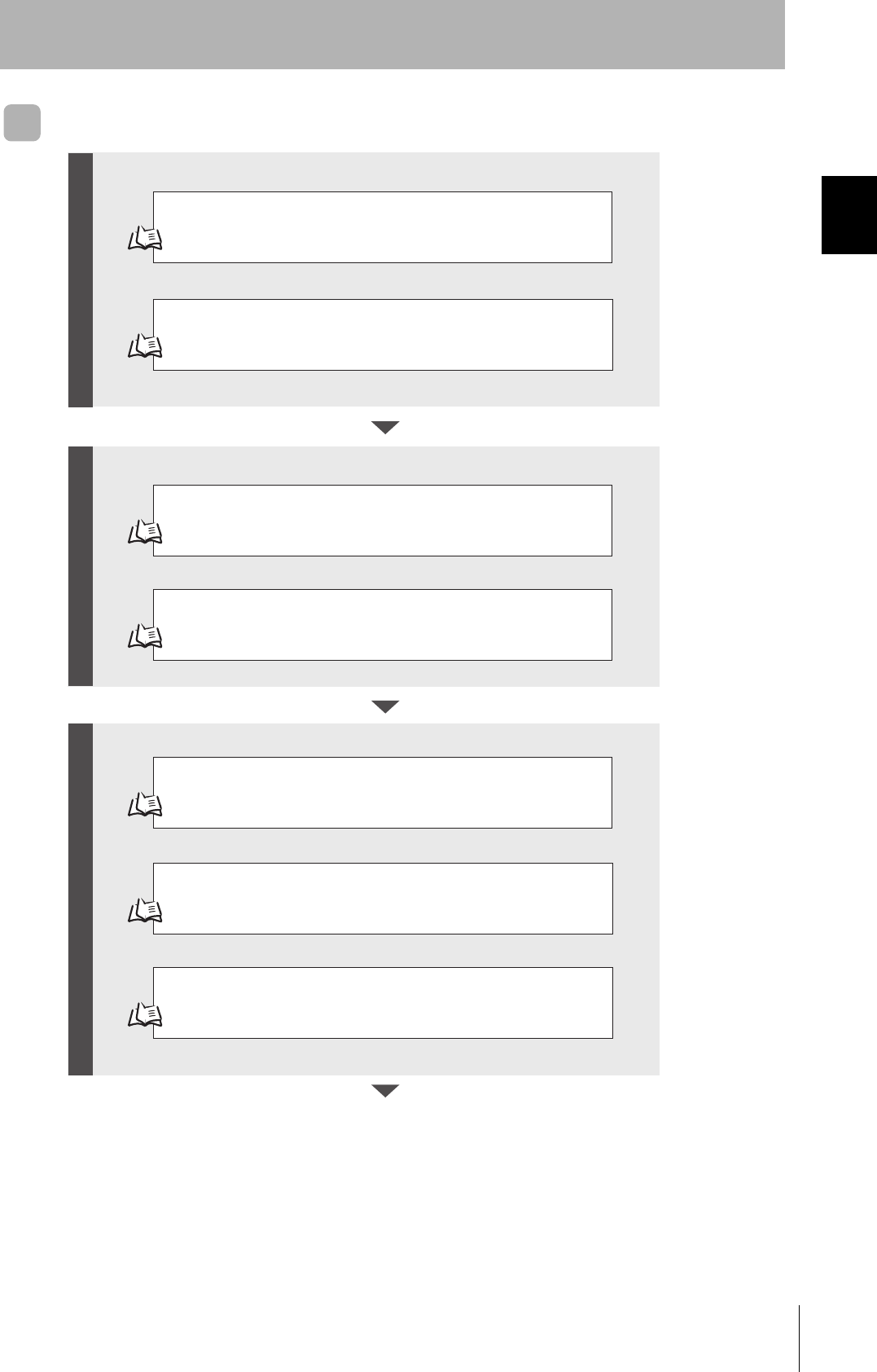
When SECS Is Not Used
Refer to page 26.
Refer to page 31.
Refer to page 61.
Refer to page 64.
Refer to page 66.
Installation
Connection and Wiring
Setting the Communications Conditions for Amplifier Units
Refer to page 63.
Setting the Communications Conditions for Link Units
Test for Communications with the Host Device
Communications Test between ID Tags and CIDRW System
Check the Surrounding Environment
Refer to page 28.
Preparation for CommunicationsTrial Operation Installation and Connections
24
SECTION 1
Flowchart for Getting Started
CIDRW System
User’s Manual
SECTION 1
Product Outline
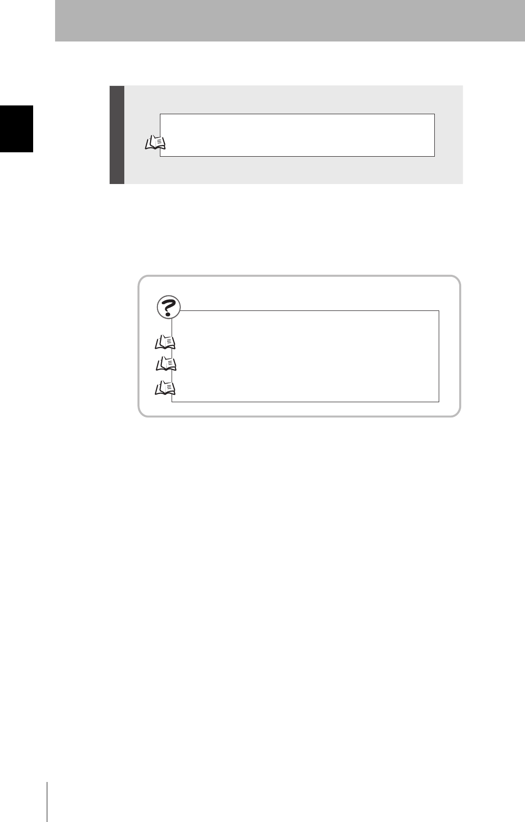
Refer to page 81.
Refer to page 102. List of Error Messages
Refer to page 102. Amplifier Unit Indicators
Refer to page 103. Operation Check Flowchart
When SECS Is Not Used
When SECS Is Not Used
If you Encounter a Problem...
Communications

SECTION 2
Installation and Connections/Wiring
25
CIDRW System
User’s Manual
SECTION 2
Installation and Connections/Wiring
Installation 26
CIDRW Controller 26
Amplifier Unit 27
CIDRW Head 28
Link Unit 30
Connections and Wiring 31
CIDRW Controller 31
Amplifier Unit 34
Link Unit 41
26
SECTION 2
Installation
CIDRW System
User’s Manual
SECTION 2
Installation and Connections/Wiring
Installation
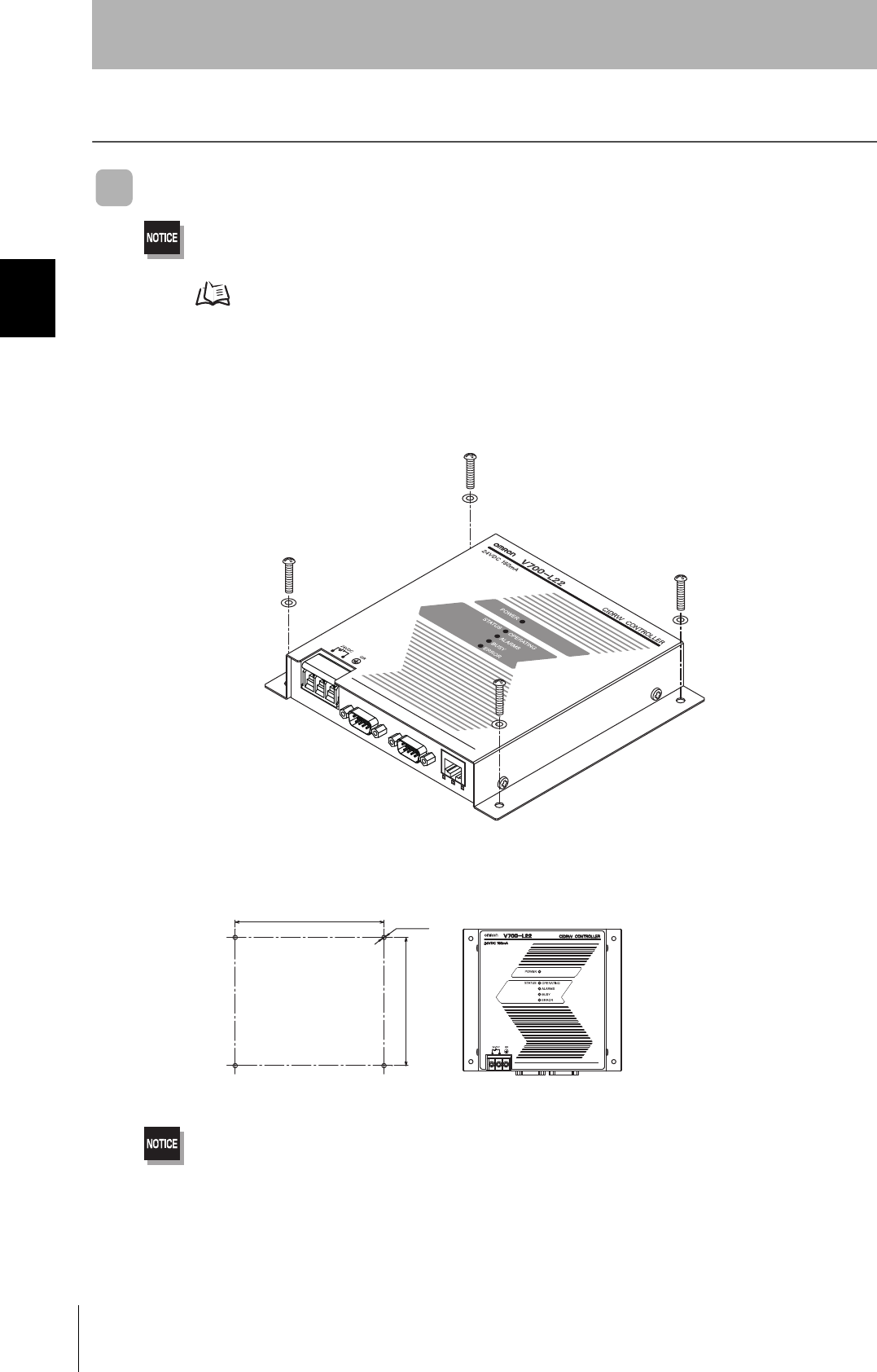
CIDRW Controller
There is a switch for selecting the operation mode (Normal Operation mode <-> Setting mode) on the bottom face of the
CIDRW Controller. Set the communications conditions in the Setting mode (switch position 3) before mounting the
CIDRW Controller.
Refer to page 48.
Set the Controller to the Normal Operation mode (switch position 0) when mounting it.
Mount the CIDRW Controller with the resin washers and four M4 screws provided as accessories.
•Tighten the M4 screws with a torque not exceeding 1.2 N·m.
• Do not apply organic solvents used with screw locking agents at the locations where the screws are inserted.
130±0.2
151±0.2 4-M4
Mounting dimensions
(Unit: mm)

27
CIDRW System
User’s Manual
SECTION 2
Installation
SECTION 2
Installation and Connections/Wiring
Amplifier Unit
Use spring washers and flat washers with the four M4 screws when mounting the Amplifier Unit.
Tighten the M4 screws with a torque not exceeding 1.2 N·m.
175±0.5
46±0.5
4-M4
Mounting dimensions
(Unit: mm)

28
SECTION 2
Installation
CIDRW System
User’s Manual
SECTION 2
Installation and Connections/Wiring
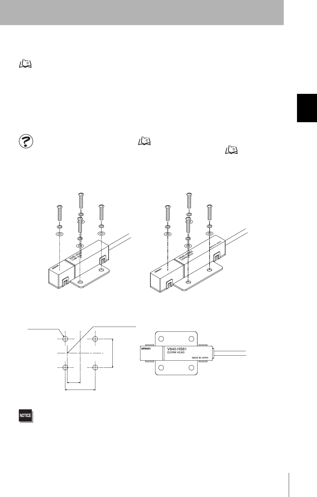
CIDRW Head
The area for communications with ID Tags varies substantially according to the installation orientations
and the background conditions (metals, noise, etc.). Check the communications area before deciding
the installation position.
For details on actual communications distances, see Characteristic Data depending on Conditions of
Use in Appendix.
Refer to page 116.
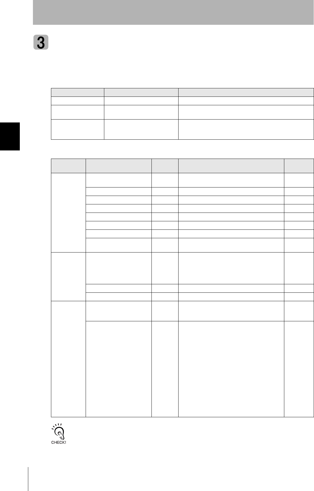
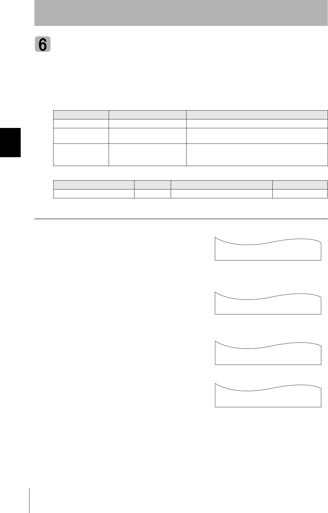
■Positional Relationship between the CIDRW Head and the ID Tag
The communications area differs according to the positional relationship during communications.
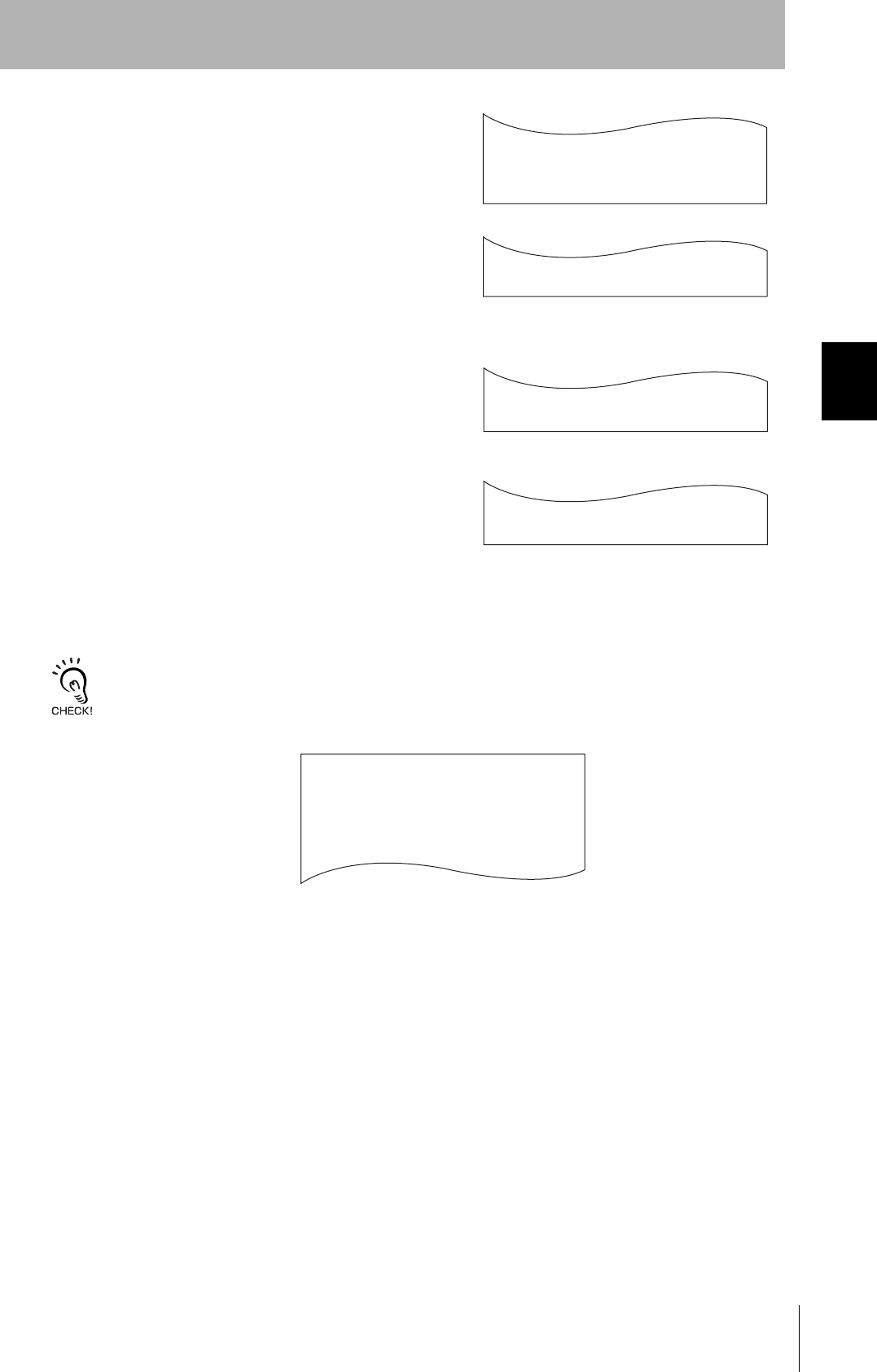
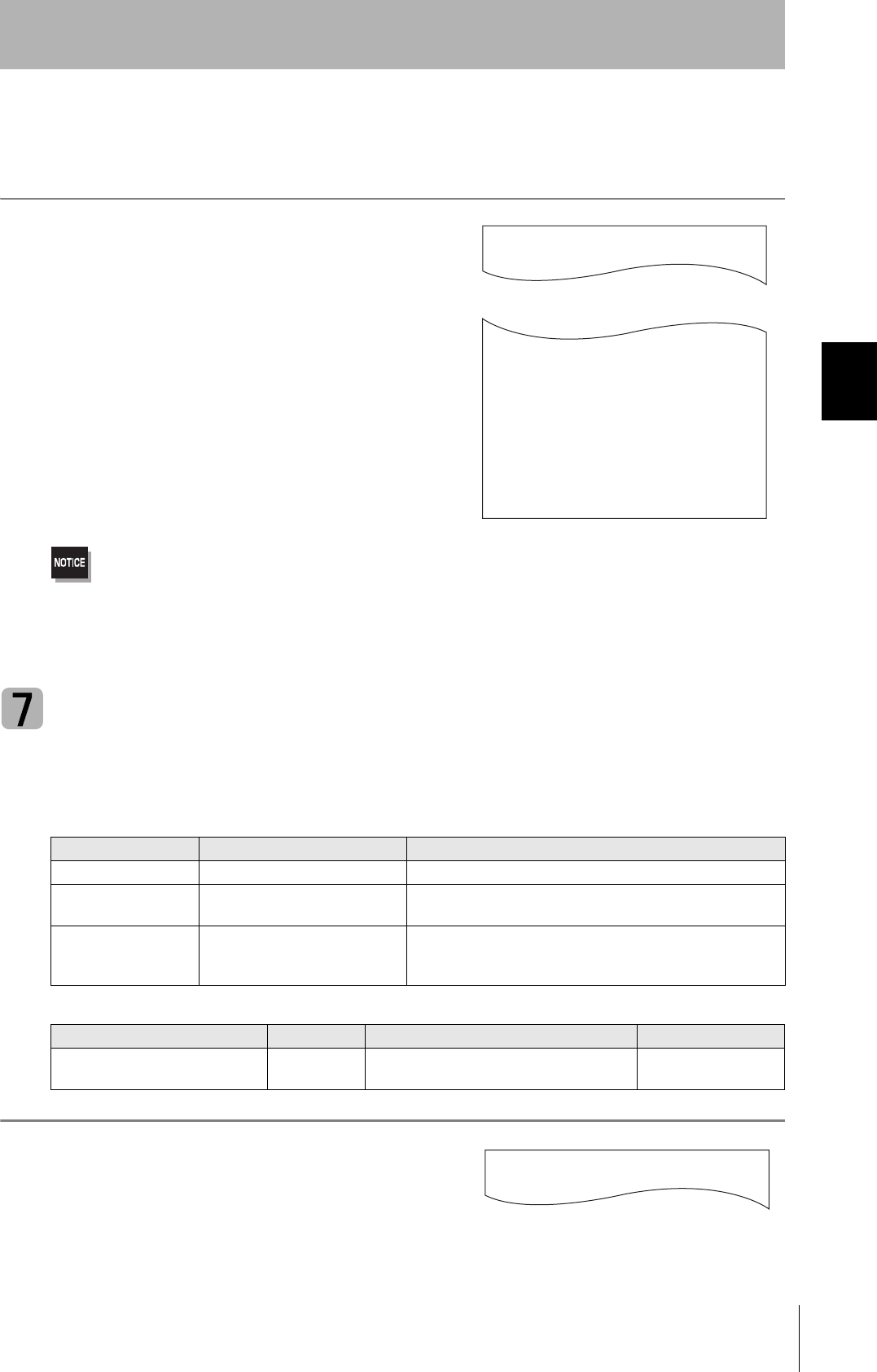
■Data Reading and Writing
The communications distances for reading and writing are not the same; the distance is shorter for
writing. Therefore, when data is to be both read and written, take the distance for writing as the refer-
ence distance when installing the CIDRW Head and the ID Tag.
Mounting
orientation Communications area (purely illustrative) Explanation
Coaxial The maximum communications area is
obtained when the center lines of the CIDRW
Head and the ID Tag coincide.
Parallel The maximum communications area is
obtained when the center point of the
antenna on the CIDRW Controller is aligned
with the center line of the ID Tag.
Vertical When the center point of the antenna on the
CIDRW Head is aligned with the center line
of the ID Tag, the communications area is
substantially reduced.
29
CIDRW System
User’s Manual
SECTION 2
Installation
SECTION 2
Installation and Connections/Wiring
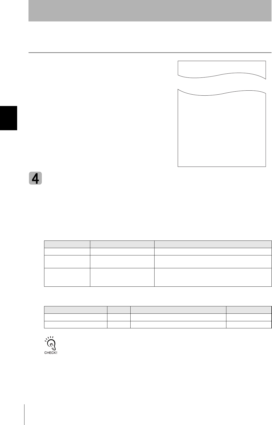
■Influence of Background Metal on ID Tag
Metals in the vicinity of the communications area will affect the range, making it smaller.
Refer to page 122.
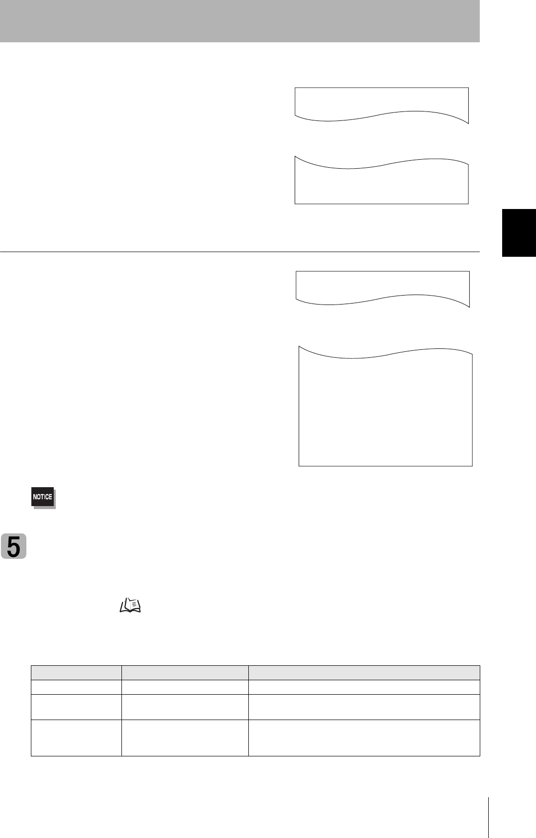
■Influence of Noise
This CIDRW system uses a frequency of 134 kHz for communications with ID Tags. Equipment such
as switching power supplies, inverters, servomotors, or monitors in the surrounding area will adversely
affect communications, restricting the communications area.
The noise levels in the vicinity of the CIDRW Head can be determined with the environmental NOISE MEASUREMENT
command (applies only when SECS is not used) . Refer to page 90.
For details on the relationship between noise and communications distance, see Appendix . Refer to page 146.
■Mounting
Use spring washers and flat washers with the four M3 screws when mounting a CIDRW Head.
Tighten the M3 screws with a torque not exceeding 0.6 N·m.
4-M3 OR φ3.5
Mounting dimensions (Unit: mm)
Antenna center
21±0.2
20±0.2
30
SECTION 2
Installation
CIDRW System
User’s Manual
SECTION 2
Installation and Connections/Wiring
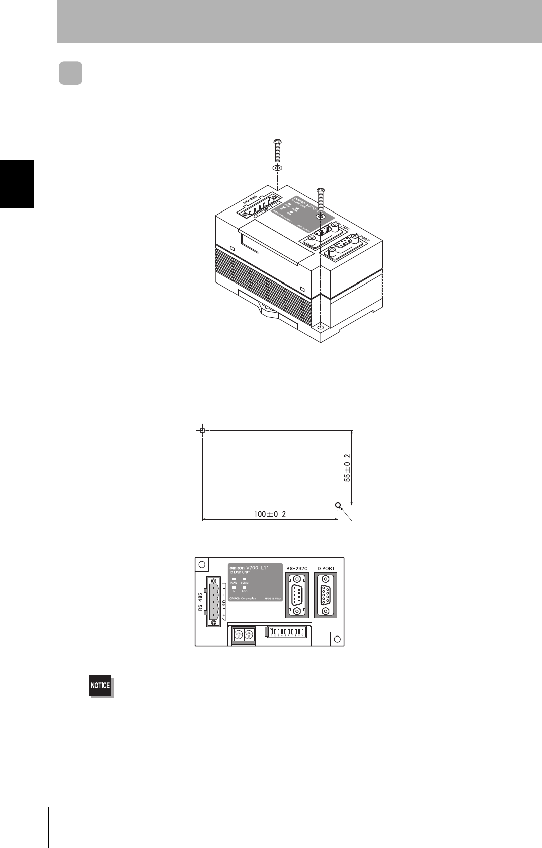
Link Unit
Mount Link Units with the two M4 screws and washers provided as accessories.
•Tighten the M4 screws with a torque not exceeding 1.2 N·m.
• Do not apply organic solvents used with screw locking agents at the locations where the screws are inserted.
Mounting dimensions
(Unit: mm)
Two M4 or 4.2-dia. holes
31
CIDRW System
User’s Manual
SECTION 2
Connections and Wiring
SECTION 2
Installation and Connections/Wiring
Connections and Wiring
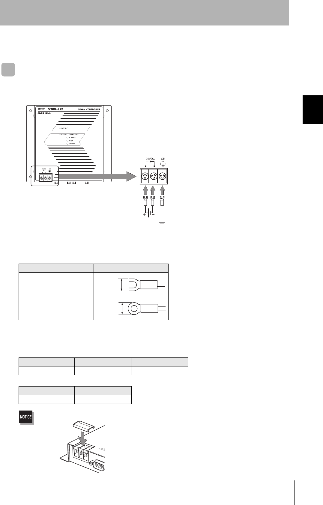
CIDRW Controller
■Power Supply and Grounding Wires
Connect the wires to the 24 VDC power supply terminals and frame ground terminal.
• Crimp Terminals
The terminal screws on the terminal block are M3 size. Use appropriate crimp terminals for M3 screws
as shown below.
• Power Supply
Use a power supply that satisfies the following conditions.
Be sure to replace the cover after wiring.
Crimp Terminals
Shape Size
Forked
Round
Condition
Power supply voltage Output current Safety standard
24 VDC +10%, -15% 500 mA DC min. UL Class 2
Recommended model
Manufacturer Model
OMRON S82K-01524
Ground to 100 Ω or less.
24 VDC
6 mm max.
6 mm max.
32
SECTION 2
Connections and Wiring
CIDRW System
User’s Manual
SECTION 2
Installation and Connections/Wiring
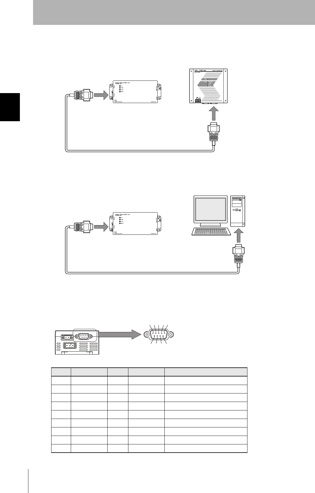
■SECS Port
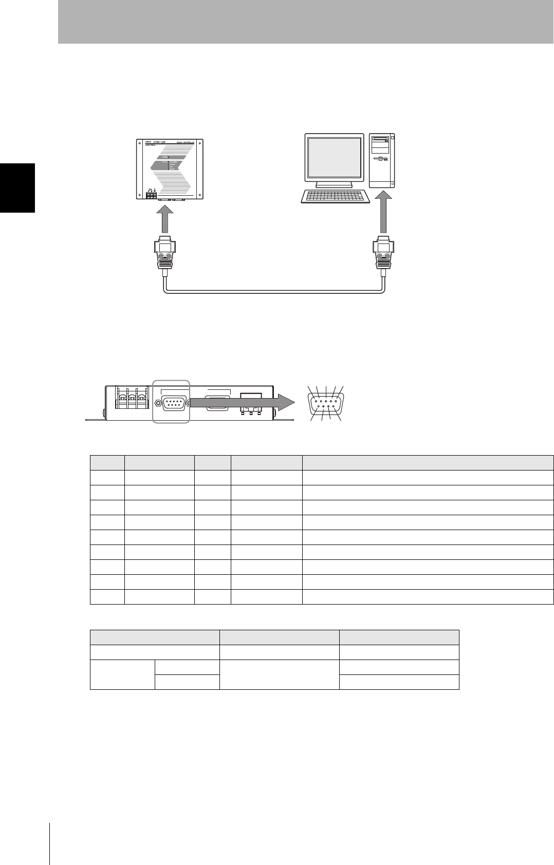
The method for wiring for communications with a host device via the SECS port is explained here.
• Connector
The SECS port on the Controller is a D-SUB 9-pin connector. The pin arrangement is shown below.
Recommended Models
Pin No. Signal name Symbol Signal direction Remarks
1 — NC — Not connected
2 Receive data RD Input
3 Send data SD Output
4 — — Output Always OFF
5 Signal ground SG —
6 — — Input Use in the open status.
7 Request send RS Input Always ON during normal operation
8 — NC — Not connected
9 — NC — Not connected
Manufacturer Model
Cable Hitachi Cable CO-MA-VV-SB 5PX28AWG
Connector Socket OMRON XM2D-0901
Hood XM2S-0913
CIDRW Controller Host
To the RS-232 port
To the SECS port
RS-232C
SECS ID MAINTENANNCE
12 3
6789
45
The connector rim has electrical continuity with the
GR (frame ground) in the 24 VDC power supply ter-
minals.
33
CIDRW System
User’s Manual
SECTION 2
Connections and Wiring
SECTION 2
Installation and Connections/Wiring
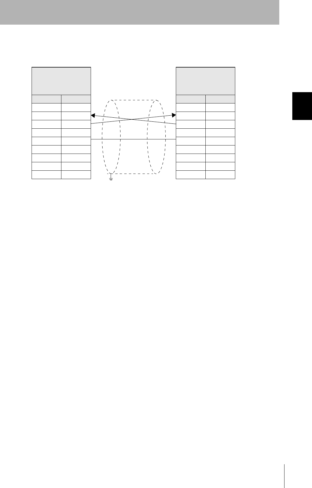
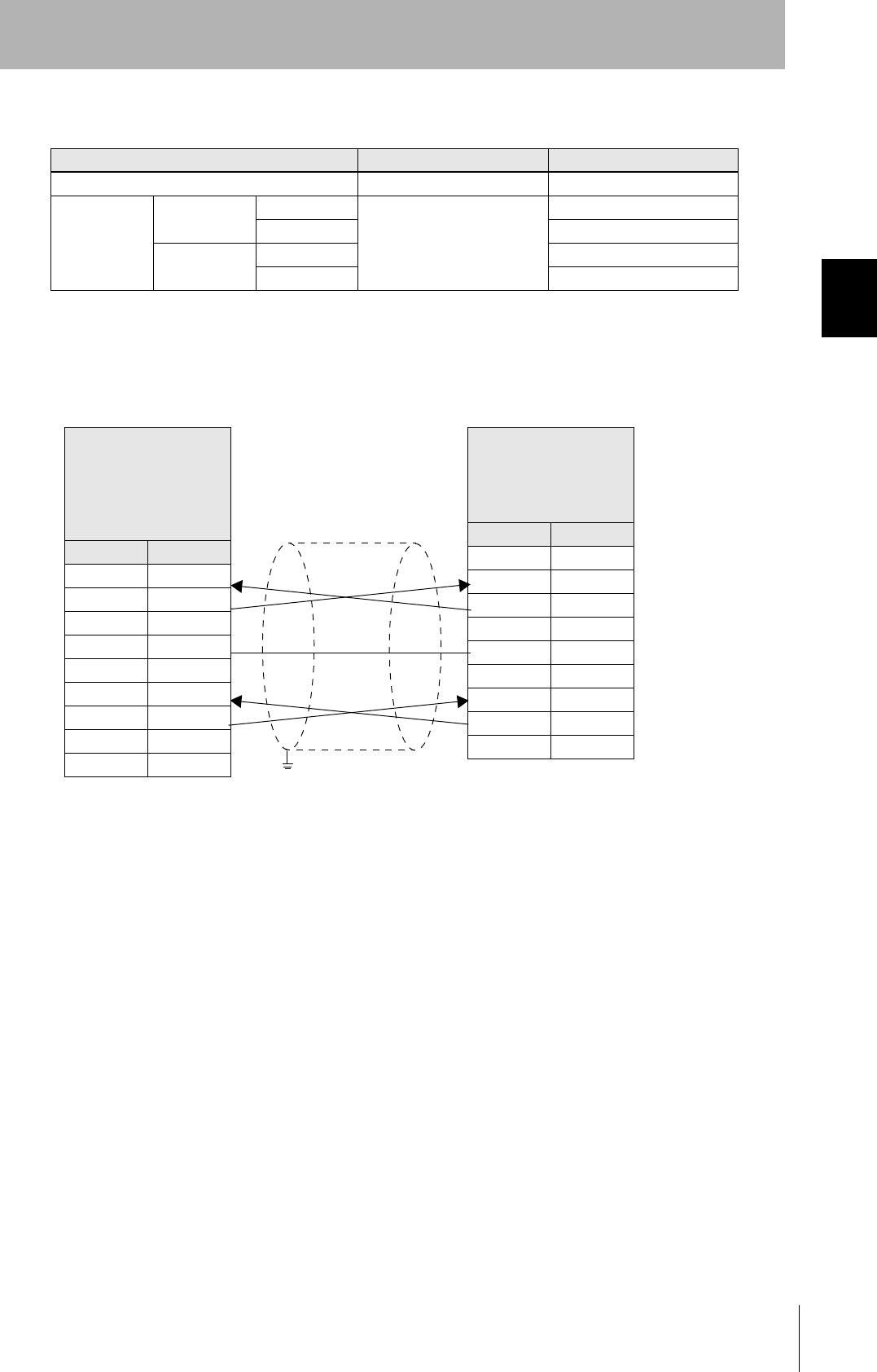
• Wiring
The cable length should be no greater than 15 m.
CIDRW Controller
V700-L22
D-SUB, 9-pin
Socket type #4-40
Name Pin No.
NC 1
RD 2
SD 3
NC 4
SG 5
NC 6
RS 7
NC 8
NC 9
PC/AT Computer
D-SUB, 9-pin
Socket type #4-40
Pin No. Name
1NC
2RD
3SD
4NC
5SG
6NC
7RS
8CS
9NC
Ground shielded wires either at the CIDRW Controller side or at the PC/AT side.
34
SECTION 2
Connections and Wiring
CIDRW System
User’s Manual
SECTION 2
Installation and Connections/Wiring
Amplifier Unit
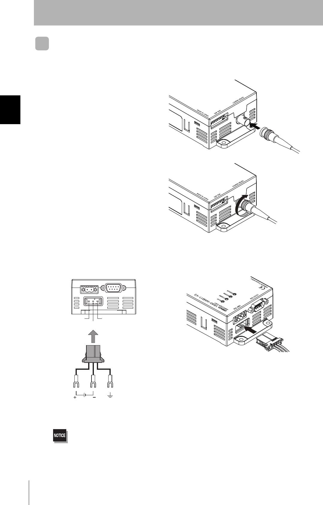
■Connector for Connecting a CIDRW Head
1. Align the pin on the connector with the
channel in the cable connector and insert
the cable connector.
Hold the fixed part of the connector while making
this insertion.
2. After inserting the connector fully home,
turn the fixed part clockwise to lock it.
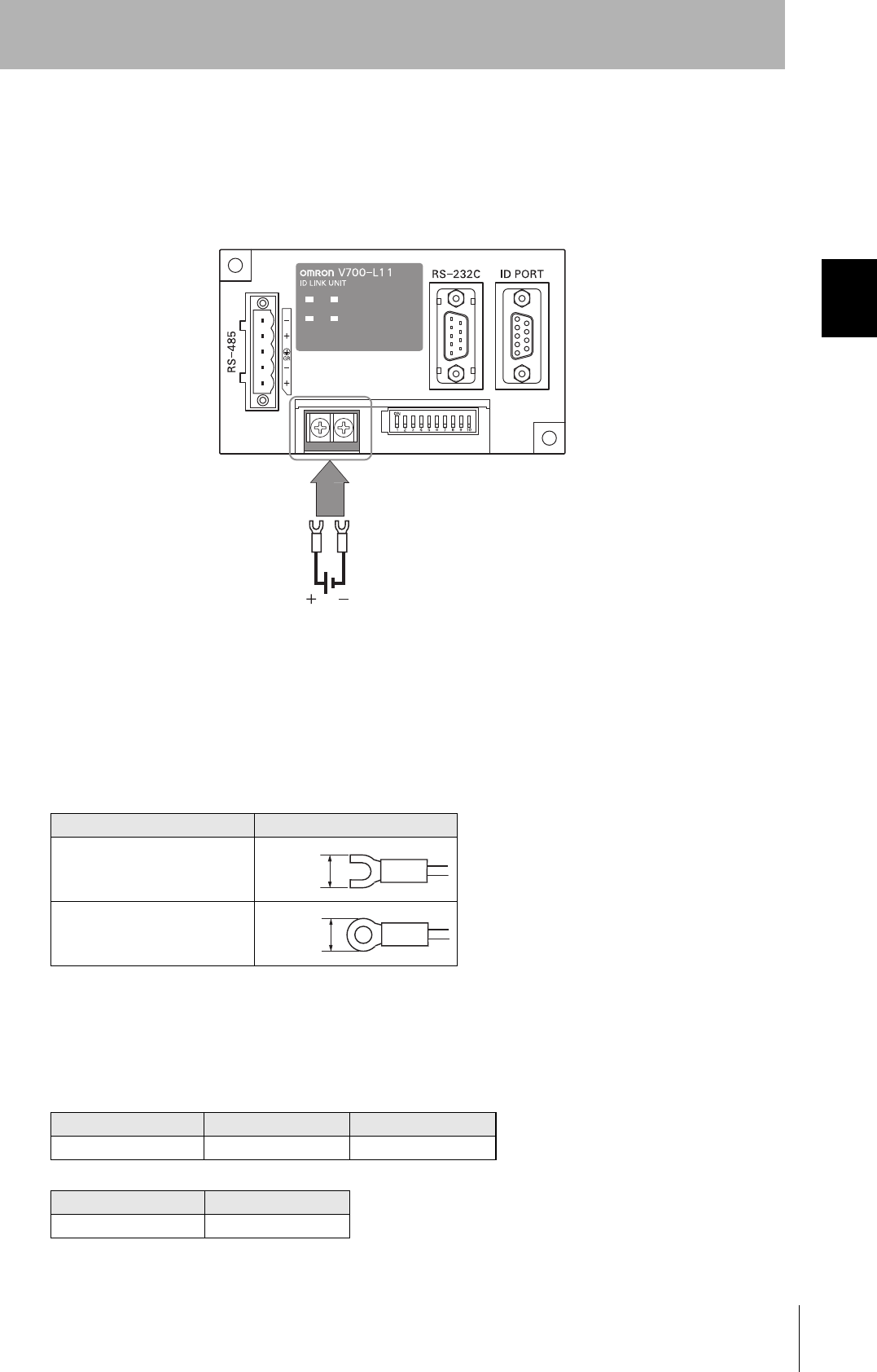
■Power Supply and Grounding Wires
Connect the power supply and grounding wires to the dedicated power supply connector.
•The grounding wire should be connected to a ground exclusive to the Amplifier Unit. If the grounding wire is shared
with another unit, or connected to a beam in a building, there may be adverse effects.
•Make the grounding point as close as possible and the length of the grounding wire used as short as possible.
•When using the Amplifier Unit in Europe, the connecting cable between the Amplifier Unit and the DC power supply
must be 3 m or less.
24 V+
24 V-
GR
24 VDC Ground to 100 Ω or less
Connector
35
CIDRW System
User’s Manual
SECTION 2
Connections and Wiring
SECTION 2
Installation and Connections/Wiring
• Dedicated Power Supply Connector and RS-485 Port Connector
Prepare a V640-A90 (can be purchased as an accessory).
• Dedicated Power Supply Cable
Use an AWG20 to AWG24 cable.
Use a dedicated tool for crimping the cable to the connector pins.
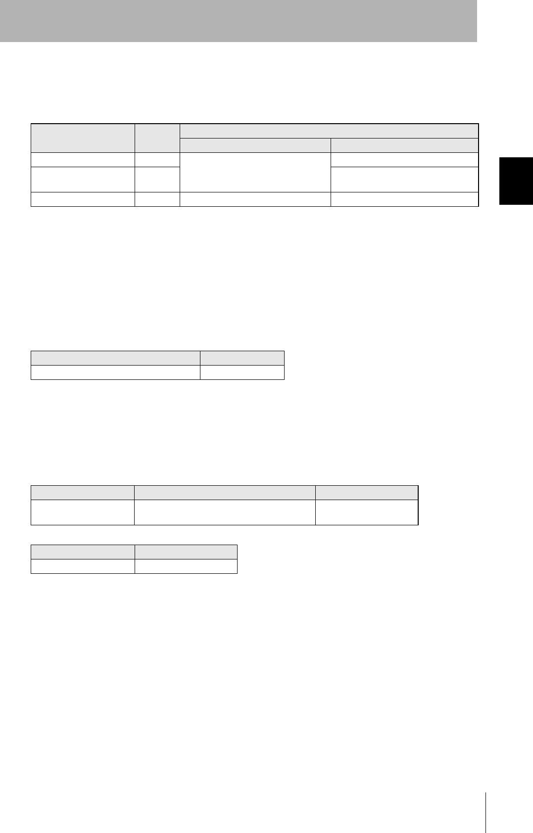
• Power Supply
Use a power supply that satisfies the following conditions.
Contents of the V640-A90 set (accessory)
Name Quantity When procured individually
Manufacturer Model
Power supply connector One Tyco Electronics 1-178288-3
Pins for power supply con-
nector
Three 175217-3
Connector for RS-485 port One Phoenix Contact MSTB2.5/2-STF-5.08
Recommended Crimping Tool
Manufacturer Model
Tyco Electronics 919601-1
Condition
Power supply voltage Output current Safety standard
24 VDC +10%, -15% V640-HAM11-ENT: 300 mA DC min.
V640-HAM11-L-ENT: 600 mA DC min.
UL Class 2
Recommended Product
Manufacturer Model
OMRON S82K-03024
36
SECTION 2
Connections and Wiring
CIDRW System
User’s Manual
SECTION 2
Installation and Connections/Wiring
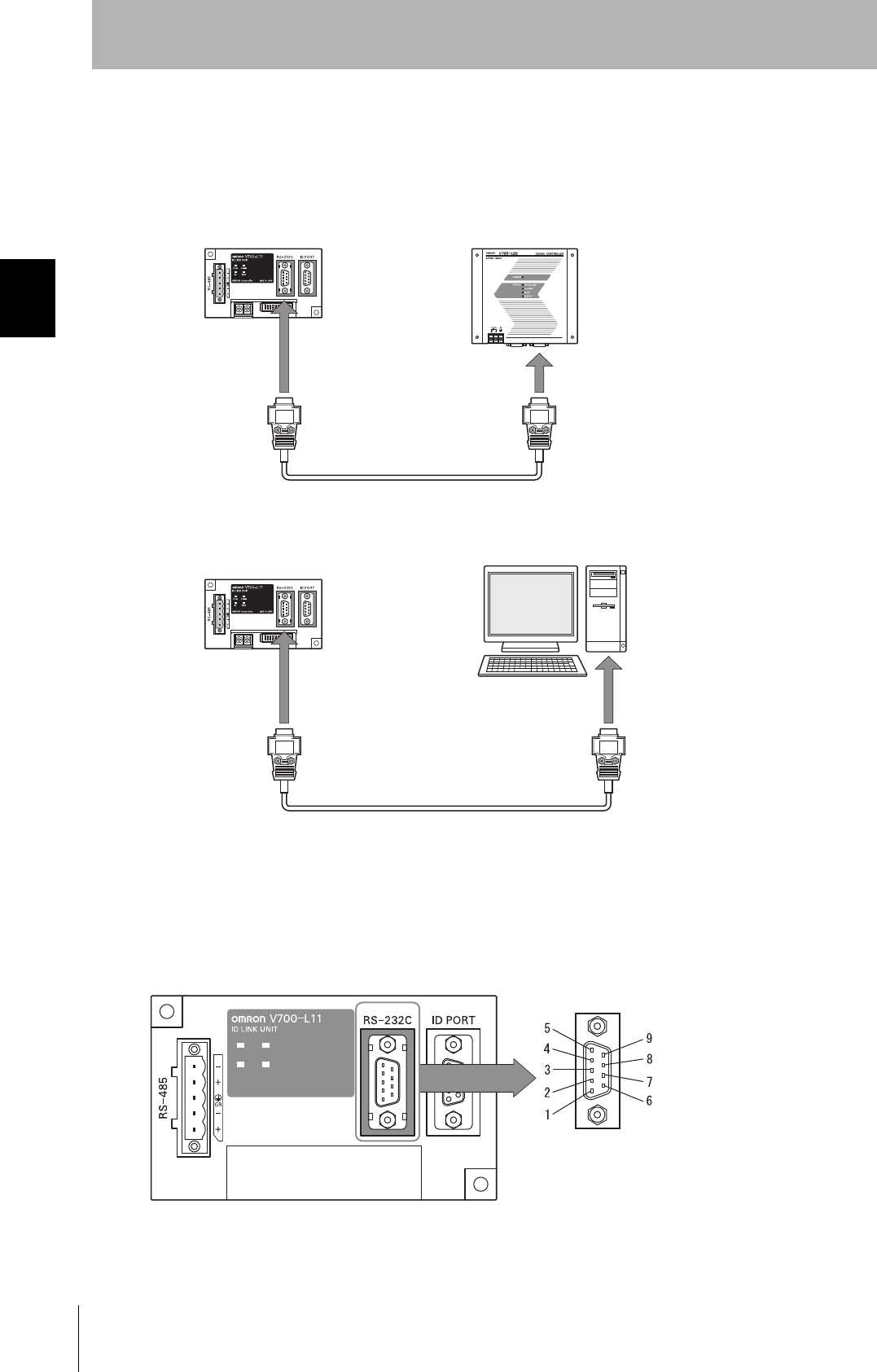
■RS-232C Port
The method for connecting a CIDRW Controller or host device via the RS-232C port is explained here.
• Connector
The RS-232C port of the Amplifier Unit is a D-SUB, 9-pin connector. The pin arrangement is shown
below.
Pin No. Signal name Symbol Signal direction Remarks
1 — NC — Not connected
2 Receive data RD Input
3 Send data SD Output
4 — NC — Not connected
5 Signal ground SG —
6 — NC — Not connected
7 Request send RS Output Always ON during normal operation
8 Send enable CS Input
9 — NC — Not connected
Host
To ID port
To the RS-232C port
Amplifier Unit
To the RS-232C port
To the RS-232C port
CIDRW Controller
Amplifier Unit
123
6789
45
The connector rim has electrical continuity with the GR (frame
ground) terminal in the dedicated power supply connector.
37
CIDRW System
User’s Manual
SECTION 2
Connections and Wiring
SECTION 2
Installation and Connections/Wiring
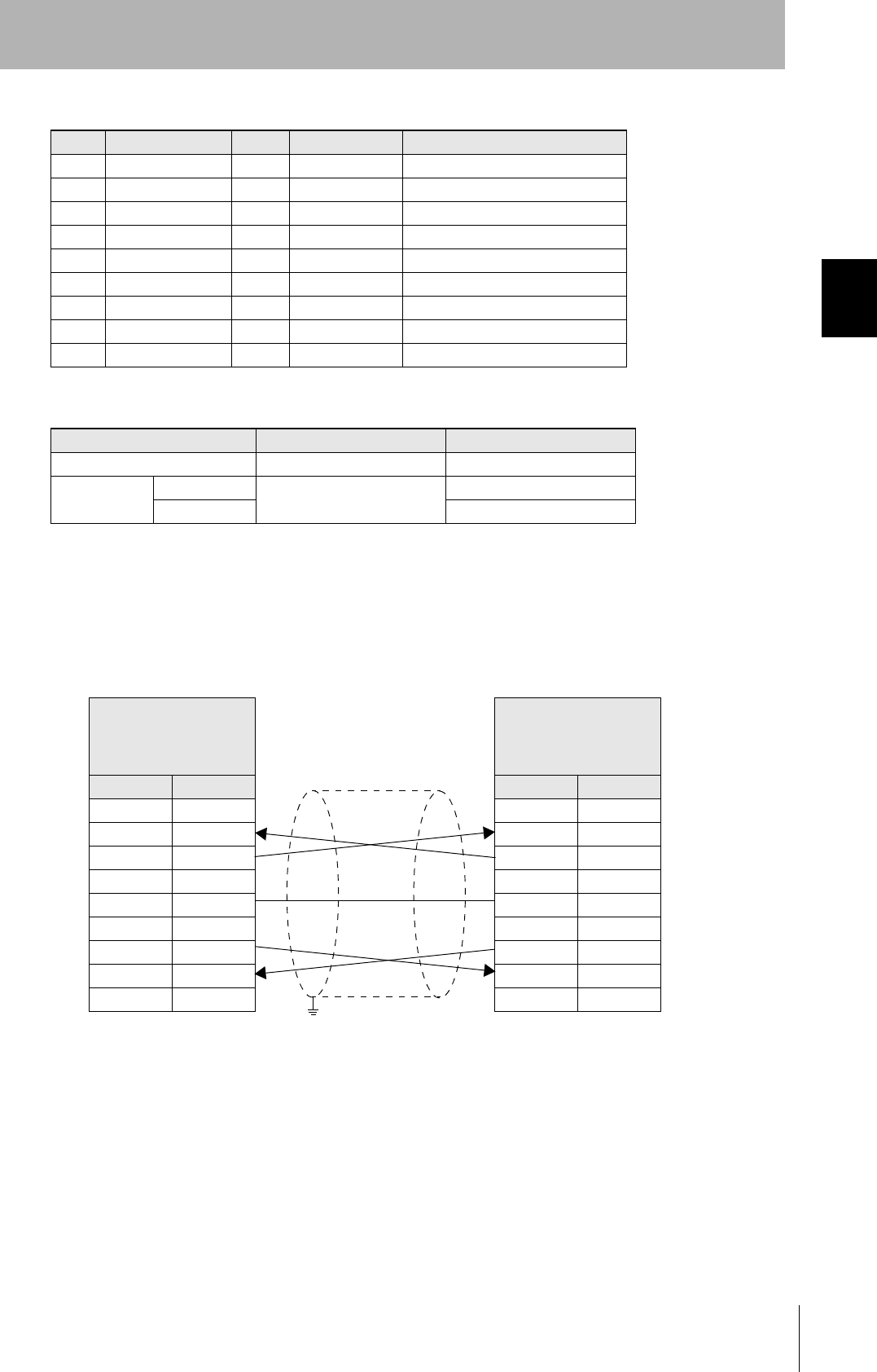
• Wiring for Connection to a V700-L22 CIDRW Controller
The cable length should be no greater than 15 m.
Recommended Models
Manufacturer Model
Cable Hitachi Cable CO-MA-VV-SB 5PX28AWG
Connector Host side Socket OMRON XM2D-0901
Hood XM2S-0913
Amplifier Unit
side
Socket XM2D-0901
Hood XM2S-0911
Amplifier Unit
V640-HAM11-V3
V640-HAM11-L
D-SUB, 9-pin
Socket type
Metric screw, M2.6
Name Pin No.
NC 1
RD 2
SD 3
NC 4
SG 5
NC 6
RS 7
CS 8
NC 9
CIDRW Controller
V700-L22
D-SUB, 9-pin
Socket type
#4-40
Pin No. Name
1NC
2RD
3SD
4NC
5SG
6NC
7RS
8CS
9NC
Ground shielded wires either at the Amplifier Unit side or at the
CIDRW side.
38
SECTION 2
Connections and Wiring
CIDRW System
User’s Manual
SECTION 2
Installation and Connections/Wiring
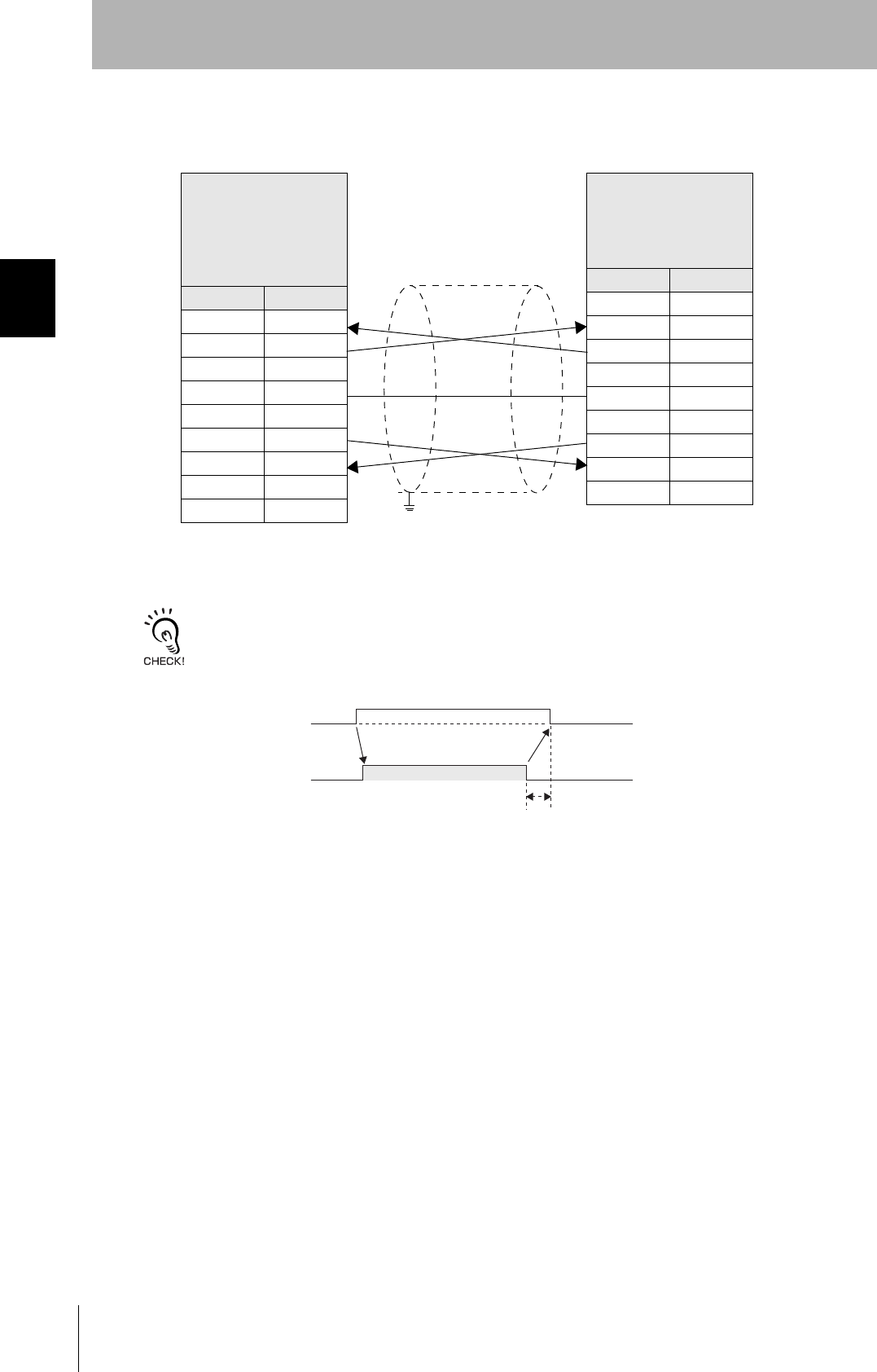
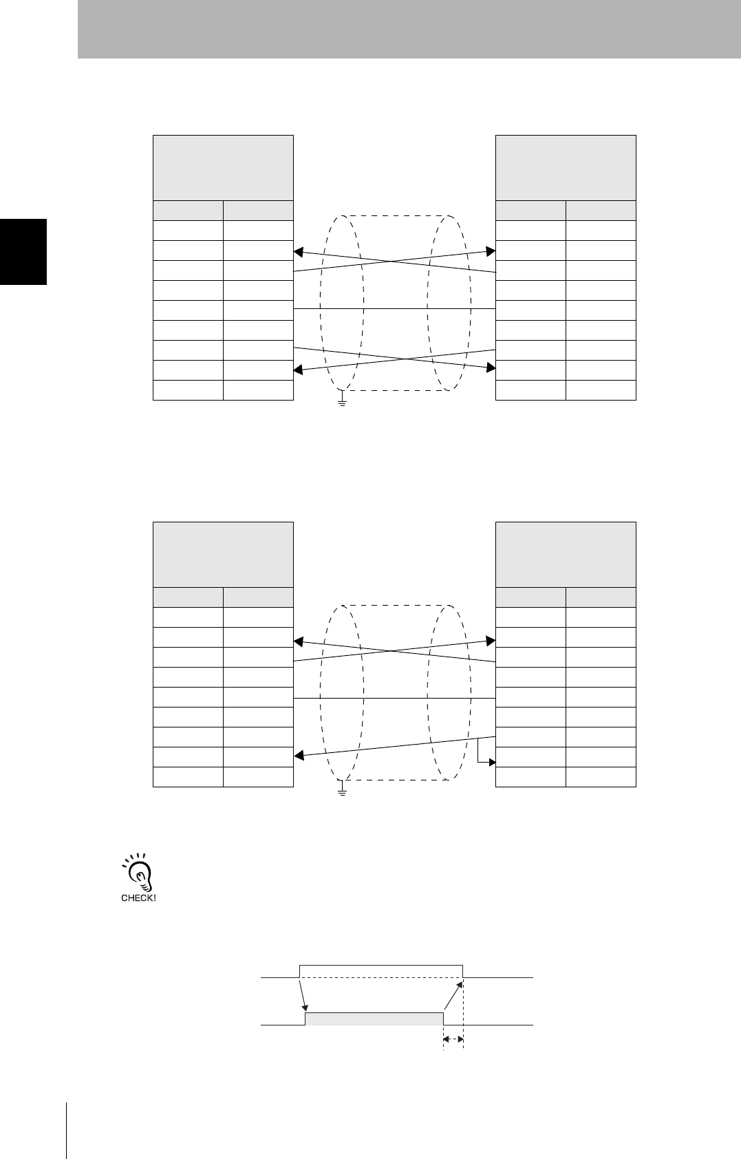
• Wiring for Connection to a PC/AT Computer (9-pin Connector)
The cable length should be no greater than 15 m.
RS signal control method at the host device
In a 1:N connection, the RS signals generated from the host device by normal control must be input as CS signals. Turn
the RS signals OFF within 15 ms after the completion of data transmission. Correct communications will not be possible
without this control.
Amplifier Unit
V640-HAM11-V3
V640-HAM11-L
D-SUB, 9-pin
Socket type
Metric screw, M2.6
Name Pin No.
NC 1
RD 2
SD 3
NC 4
SG 5
NC 6
RS 7
CS 8
NC 9
PC/AT Computer
D-SUB, 9-pin
Socket type
#4-40
Pin No. Name
1NC
2RD
3SD
4NC
5SG
6NC
7RS
8CS
9NC
Ground shielded wires either at the CIDRW Controller side or at the
PC/AT side.
SD at host device
RS at host device
ON only during data transmission from the host device
Within 15 ms

39
CIDRW System
User’s Manual
SECTION 2
Connections and Wiring
SECTION 2
Installation and Connections/Wiring
■RS-485 Port
The method for connection to the RS-485 port of another Amplifier Unit when multiple CIDRW Heads
are used is explained here.
The maximum total length of RS-485 cable is 50 m.
• Connector
Prepare a V640-A90 (can be purchased as an accessory) as the connector for the RS-485 port on the
Amplifier Unit.
Refer to page 35.
The pin arrangement is shown below.
To the RS-485 port Amplifier Unit
To the RS-232C port
CIDRW Controller
Connector
Name Function
- Connect to the minus line of another Amplifier Unit.
+ Connect to the plus line of another Amplifier Unit.
40
SECTION 2
Connections and Wiring
CIDRW System
User’s Manual
SECTION 2
Installation and Connections/Wiring
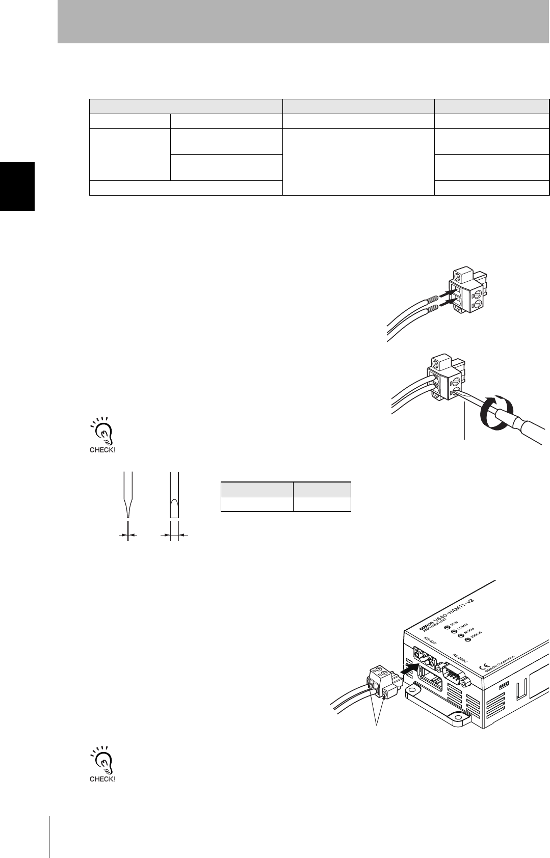
• Cable Information
• Wiring Method
1. Attach crimp terminals to stripped portions of the cables.
2. Insert the wires into the correct holes in the connector, bearing
the orientation of the connector in mind.
3. Tighten the set screws of the connector firmly to secure the
cables.
The appropriate tightening torque is around 0.5 N·m.
A standard, tapered screwdriver will not enter all the way into the
screw holes. Use a small gauge flat-blade screwdriver whose shaft
and tip have the same thickness.
4. Having fitted the connector to the cable, connect it
to an Amplifier Unit.
Orient the cable connector correctly in relation to the connector
on the Amplifier Unit, and fasten the cable connector by fully
tightening the retaining screws.
Disconnecting the connector
Fully loosen the two screws, then grip the projections on the connector and pull it straight out. If it is difficult to pull the
connector out, press down on the Amplifier Unit while pulling on the connector.
Recommended Models
Manufacturer Model
Cable RS-485 signal wire Tachii Electric Wire MVVS 2CX0.5SQ
Crimp terminals When one wire is connected
to each terminal.
Phoenix Contact AI0.5-8WH
When two wires are con-
nected to each terminal.
AI-TWIN2×0.5-8WH
Crimping tool CRIMPFOX UD6
Small flat-blade screw-
driver with no taper
Recommended Screwdriver
Manufacturer Model
OMRON XW4Z-00C
Side view Face view
0.6 mm 3.5 mm
Set screws
41
CIDRW System
User’s Manual
SECTION 2
Connections and Wiring
SECTION 2
Installation and Connections/Wiring
Link Unit
■Power Supply
Opening the cover on the top face of the Link Unit exposes the power supply terminals.
• Crimp Terminals
The terminal screws on the terminal block are M3 size. Use appropriate crimp terminals for M3 screws
as shown below.
• Power Supply
Use a power supply that satisfies the following conditions.
Crimp Terminals
Shape Size
Forked
Round
Condition
Power supply voltage Output current Safety standard
24 VDC +10%, -15% 500 mA DC min. UL Class 2
Recommended Model
Manufacturer Model
OMRON S82K-01524
24 VDC
6 mm max.
6 mm max.
42
SECTION 2
Connections and Wiring
CIDRW System
User’s Manual
SECTION 2
Installation and Connections/Wiring
■Host Connection Port
The method for connecting to a CIDRW Controller or host device via the RS-232C port is explained
here.
• Connector
The host device connection port on the Link Unit is a D-SUB, 9-pin connector. The pin arrangement is
shown below.
CIDRW Controller
Link Unit
To ID port
To the RS-232C port
To host device port
Link Unit
To host device port
Host
The connector rim does not have electrical
continuity with the GR (frame ground) termi-
nal in the multi-connection port.
43
CIDRW System
User’s Manual
SECTION 2
Connections and Wiring
SECTION 2
Installation and Connections/Wiring
• Wiring for Connection to a CIDRW Controller
The cable length should be no greater than 15 m.
Pin No. Signal name Symbol Signal direction Remarks
1 — NC — Not connected
2 Receive data RD Input
3 Send data SD Output
4 — NC — Not connected
5 Signal ground SG —
6 — NC — Not connected
7 Request send RS Output Always ON during normal operation
8 Send enabled CS Input
9 — NC — Not connected
Recommended model
Manufacturer Model
Cable Hitachi Cable CO-MA-VV-SB 5PX28AWG
Connector Socket OMRON XM2D-0901
Hood XM2S-0913
Link Unit
V700-L11
D-SUB, 9-pin, female
Socket type #4-40
Name Pin No.
NC 1
RD 2
SD 3
NC 4
SG 5
NC 6
RS 7
CS 8
NC 9
CIDRW Controller
V700-L22
D-SUB, 9-pin, female
Socket type #4-40
Pin No. Name
1NC
2RD
3SD
4NC
5SG
6NC
7RS
8CS
9NC
Ground shielded wires at the CIDRW Controller side.
44
SECTION 2
Connections and Wiring
CIDRW System
User’s Manual
SECTION 2
Installation and Connections/Wiring
• Wiring for Connection to a PC/AT Computer
If the CS function is to be used at the PC/AT computer side, a return wire is required.
RS signal control method at the host device
In a 1:N system using Link Units, the RS signals generated from the host device by normal control must be input as CS
signals. Turn the RS signals OFF within 15 ms after the completion of data transmission. Correct communications will
not be possible without this control.
Link Unit
V700-L11
D-SUB, 9-pin
Socket type #4-40
Name Pin No.
NC 1
RD 2
SD 3
NC 4
SG 5
NC 6
RS 7
CS 8
NC 9
PC/AT Computer
D-SUB, 9-pin
Socket type #4-40
Pin No. Name
1NC
2RD
3SD
4NC
5SG
6NC
7RS
8CS
9NC
Ground shielded wires at the PC/AT computer side.
Link Unit
V700-L11
D-SUB, 9-pin
Socket type #4-40
Name Pin No.
NC 1
RD 2
SD 3
NC 4
SG 5
NC 6
RS 7
CS 8
NC 9
PC/AT Computer
D-SUB, 9-pin
Socket type #4-40
Pin No. Name
1NC
2RD
3SD
4NC
5SG
6NC
7RS
8CS
9NC
Ground shielded wires at the PC/AT computer side.
SD at host device
RS at host device
ON only during data transmission from the host device
Within 15 ms
45
CIDRW System
User’s Manual
SECTION 2
Connections and Wiring
SECTION 2
Installation and Connections/Wiring
■Multi-connection Port
The method for connecting to an Amplifier Unit is explained here.
• Connector
Pin No. Name Function
5 - No wiring is required. (Short with terminal 2 within the circuit)
4 + No wiring is required. (Short with terminal 1 within the circuit)
3 GR Ground to 100 Ω or less.
2 - Connect to the minus line of the Amplifier Unit.
1 + Connect to the plus line of the Amplifier Unit.
Link Unit
Amplifier Unit
To the RS-485 port
To multi-connection port
46
SECTION 2
Connections and Wiring
CIDRW System
User’s Manual
SECTION 2
Installation and Connections/Wiring
• Cable
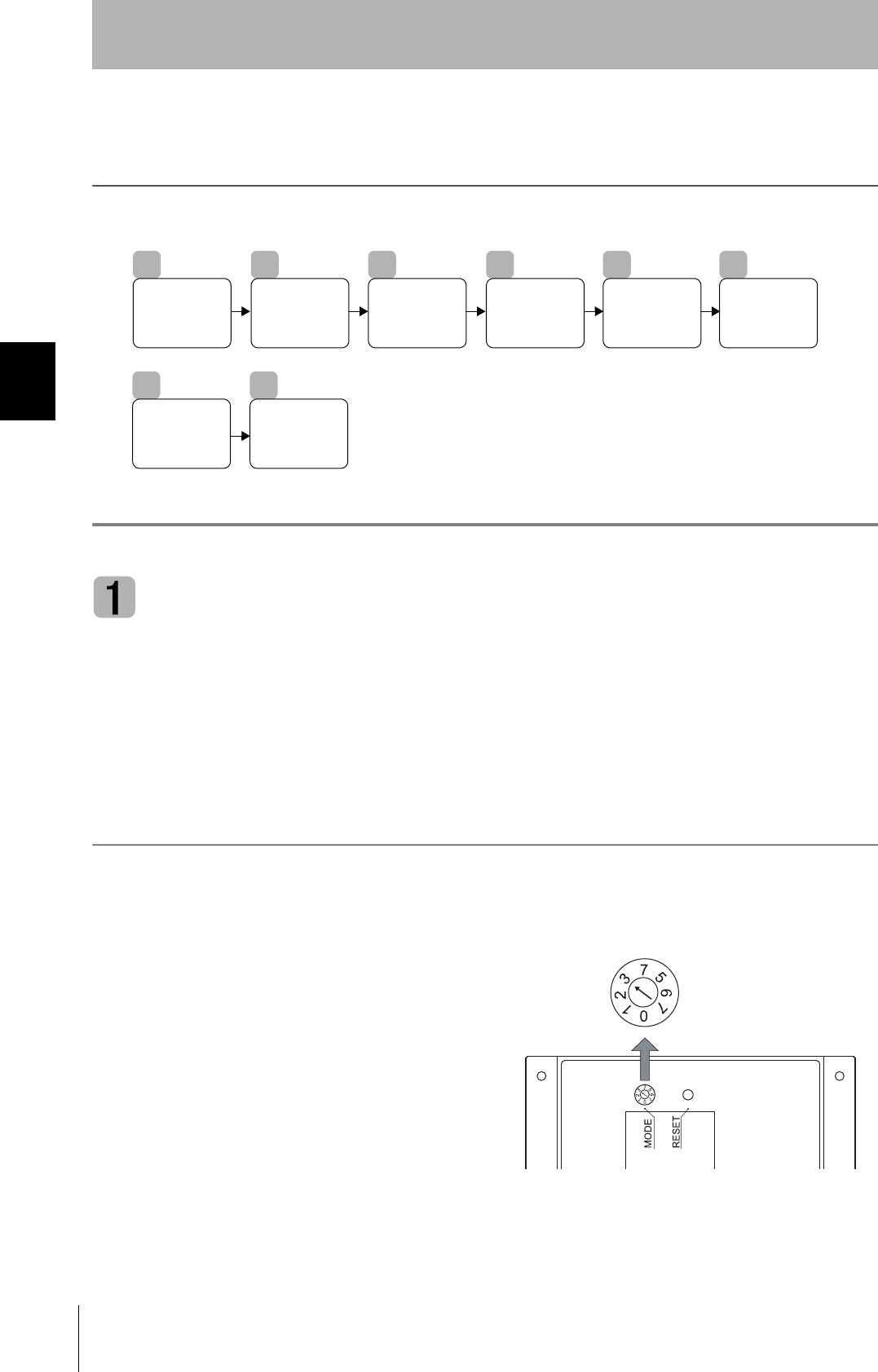
• Wiring Method
1. Attach crimp terminals to stripped portions of the cables.
2. Insert the wires into the correct holes in the connector, bearing
the orientation of the connector in mind.
3. Tighten the set screws of the connector firmly to secure the
cables.
The appropriate tightening torque is around 0.5 N·m.
A standard, tapered screwdriver will not enter all the way into the
screw holes. Use a small gauge flat-blade screwdriver whose shaft
and tip have the same thickness.
4. Having fitted the connector to the cable, connect
it to the Link Unit.
Orient the cable connector correctly in relation to the connec-
tor on the Link Unit, and fasten the cable connector by fully
tightening the retaining screws.
Disconnecting the connector
Fully loosen the two screws, then grip the projections on the connector and pull it straight out. If it is difficult to pull the
connector out, press down on the Link Unit while pulling on the connector.
Recommended Models
Manufacturer Model
Cable RS-485 signal wire Tachii Electric Wire MVVS 2CX0.5SQ
Frame ground line AWG22 to AWG20 cable
Crimp terminals When one wire is connected to each terminal. Phoenix Contact AI0.5-8WH
When two wires are connected to each terminal. AI-TWIN2×0.5-8WH
Crimping tool CRIMPFOX UD6
Small gauge flat-blade
screwdriver with no taper
Recommended screwdriver
Manufacturer Model
OMRON XW4Z-00C
Side view Face view
0.6 mm 3.5 mm
Set screws

SECTION 3
Preparing for Communications
47
CIDRW System
User’s Manual
SECTION 3
Preparing for Communications
Setting the Communications Conditions for the CIDRW Control-
ler48
Setting the Communications Conditions for Amplifier Units 61
Setting the Communications Conditions for Link Units 63
Communications Test 64
48
SECTION 3
Setting the Communications Conditions for the CIDRW Controller
CIDRW System
User’s Manual
SECTION 3
Preparing for Communications
Setting the Communications Conditions for the
CIDRW Controller
Set the communications conditions of the CIDRW Controller only when SECS is used.
Switch to Setting Mode
The CIDRW Controller has two operating modes, the Normal Operation mode and the Setting mode.
Switch to the Setting mode to set the communications conditions.
There are two methods for switching the mode. Use the one that is appropriate for the circumstances.
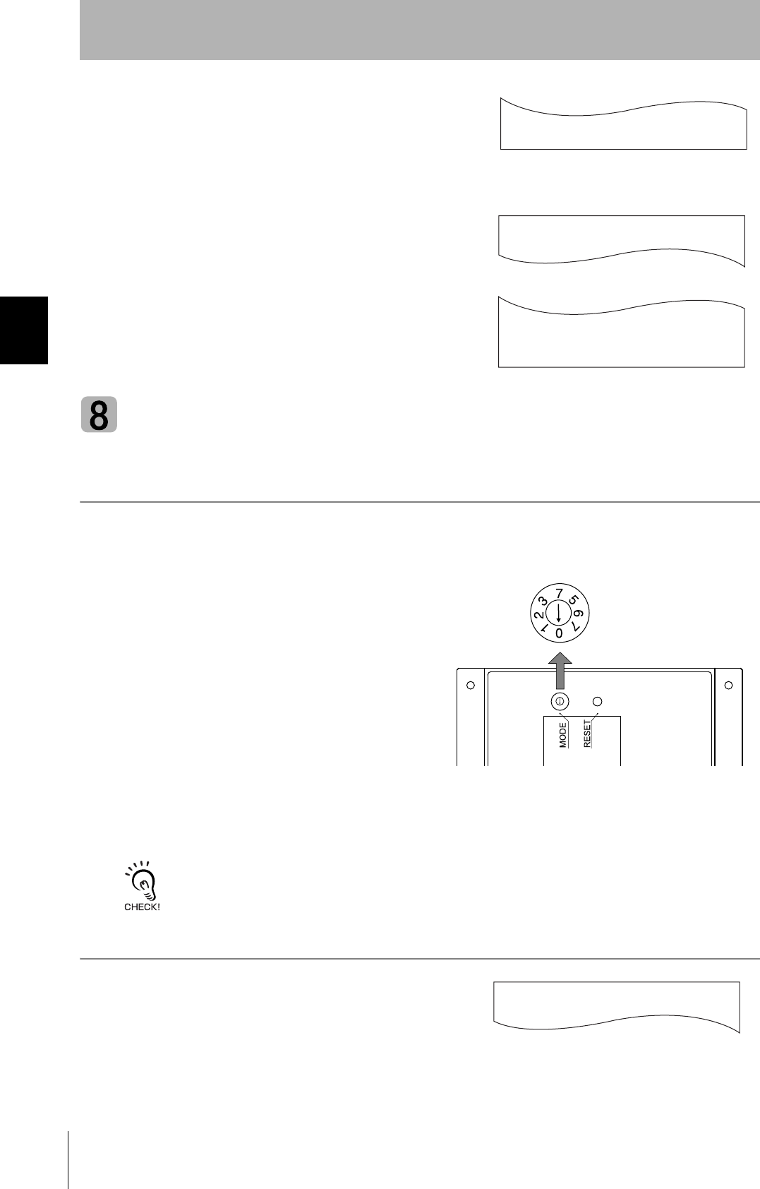
■Changing the Position of the Mode Switch on the Bottom of the Unit
This is the convenient method for setting before mounting the Unit.
1. Turn OFF the power to the CIDRW Controller.
2. Set the mode switch on the bottom of the Unit
to 3.
1
Switch to
Setting Mode
2
Start Terminal
Software
3
Set Parameters
for
Communications
Conditions.
4
Change
Carrier ID
5
Change Data
Segment
Area
6
Change
Response
Time-out
Time
7
Set Software
Revisions
8
Return to
Normal
Operation
Mode
49
CIDRW System
User’s Manual
SECTION 3
Setting the Communications Conditions for the CIDRW Controller
SECTION 3
Preparing for Communications
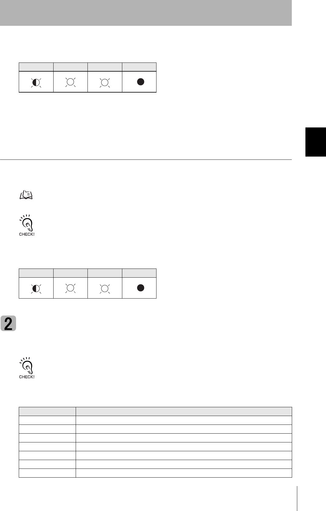
3. When all of the devices to be used are connected, turn the power ON.
The system starts up in the Setting mode, and the indicators react as shown below.
■Sending a Switching Command from the Host Device
This method is convenient when the Unit has already been mounted and the switch on the bottom can-
not be repositioned to 3.
During operation in the Normal Operation mode, a command is sent from the host device to switch to
the Setting mode.
1. Send a subsystem command (S18F13 ChangeState CPVAL1 = "PS") from the host device.
Refer to page 77.
CPVAL1="PS" is an expansion designation unique to V700-L22 and does not conform to SEMI standards.
The system is automatically restarted and the mode switches to the Setting mode.
The operation indicators react as shown below.
Start Terminal Software
Use terminal software at the host device to set the CIDRW Controller.
The commands and communications conditions in the setting mode are unique to OMRON. They do not conform to the
SEMI standards. For the terminal software, use Hyper Terminal, which is standard with Windows, or a similar program.
The communications conditions for communications between the host device and CIDRW Controller
are fixed. Make the following settings using the terminal software.
OPERATING ALARMS BUSY ERROR
OPERATING ALARMS BUSY ERROR
Item Setting
Baud rate 9600 bps
Data length 8 bits
Parity EVEN
Stop bits 1
Communications control None
Send code At the end of a line (when [ENTER] is input), the line feed characters ([LF]) are appended.
Display Local echo
50
SECTION 3
Setting the Communications Conditions for the CIDRW Controller
CIDRW System
User’s Manual
SECTION 3
Preparing for Communications
Set Parameters for Communications Conditions
Specify the parameters whose settings are to be changed from the terminal software of the host
device. The commands, and the parameters that can be set are indicated below.
The setting mode commands do not conform to SEMI standards.
For the terminal software, use Hyper Terminal, which is standard with Windows, or a similar program.
List of Commands
Designation Command Input Explanation
Parameter designation (Tag name) = (Set value) <CRLF> Specify the parameter value corresponding to the tag name.
Parameter confirmation ::END Checks the parameter designations that have been received so
far and, if there is no error, confirms the settings.
Comment # (Comment) <CRLF>
or
CRLF
This is ignored as the comment line.
Tag Name List
Classification Parameter Tag name Setting range
Default
setting
Protocol Baud Rate S_BAUD 1200, 2400, 4800, 9600, 19200, 38400, 57600,
115200 bps
9600 bps
Device ID S_DEVID 0 to 32767 0
Time-out between characters S_T1 0.1 to 10 s 0.5 s
Protocol time-out S_T2 0.2 to 25 s 10 s
Response time-out S_T3 1 to 120 s 45 s
Time-out between blocks S_T4 1 to 120 s 45 s
Retry limit S_RTY 0 to 31 3
Master/slave S_MS M: Master
S: Slave
M
SECS Double block detection yes/no S_DB 1: The header of the block currently being
received is compared with the correct block
received immediately before, and double
blocks are detected.
0: Double block detection is not performed.
0
Source ID S_SRC 0 to 32767 0
Single block No. S_BNO 0, 1 1
Operation Baud rate for communications
with Amplifier Unit/Link Unit
C_BAUD 9600, 19200, 38400 bps
Use a consistent baud rate setting within the
same system configuration.
9600 bps
Number of Heads count pro-
cessing
C_HEAD 0 to 31
0: The number of Heads is automatically
detected at the start. Any increase or
decrease in the number of Heads is auto-
matically detected.
1 to 31: The number of Heads is specified. The
number of Heads detected is compared
with this specified number of Heads. If
the number of Heads changes, for exam-
ple because a Head fails, an error (with
alarm) is detected.
If a Head is not connected or an error is
detected with a connected Head, so that
the number of Heads does not match the
specified number, an error (with alarm) is
detected.
0
51
CIDRW System
User’s Manual
SECTION 3
Setting the Communications Conditions for the CIDRW Controller
SECTION 3
Preparing for Communications
1. Specify the parameters to be changed.
When the first parameter is specified, the ALARMS indicator flashes.
2. Confirm the parameter change.
The input parameter is checked and written.
When writing is completed, a message indicating the result is displayed.
The ALARMS indicator lights.
If writing is completed with an error, the parameters are not updated.
The figure in square brackets [ ] indicates the line number where the
error was first detected. If a parity error is detected in the received char-
acters, this figure is [0].
Check the sent data based on this information.
A text file is created based on the data that is keyed in, as shown below, and this data can be conveniently transmitted
using the terminal's text file send function.
S_BAUD=19200
S_DEVID=1
S_BNO=0
_
::END
_
SETUP_COMPLETE
_
SETUP_FAILED [2]_
When writing is completed without error
When writing is completed with an error
#Parameter Setting File for SystemA
#Protocol
S_BAUD=19200
S_DEVID=1
#SECS
S_BNO=0
::END
Example: PRM.TXT
52
SECTION 3
Setting the Communications Conditions for the CIDRW Controller
CIDRW System
User’s Manual
SECTION 3
Preparing for Communications
■Check for Correct Setting
The currently set data can be output so that you can check if it is correct.
1. Send the parameter output command "::GET_PARAM"
from the host device.
The current communications parameter settings are displayed.
Change Carrier ID
To read the carrier ID, the CID has to be specified within the area where the carrier ID can be set
(CarrierIDField) within the ID Tag memory. This section explains the procedure for setting the carrier ID
offset (attribute name: CarrierIDOffset) and the carrier ID size (bytes) (attribute name:
CarrierIDLength) in the memory map of the ID Tag.
The commands, and the parameters that can be set, are given below.
• Settings that exceed the carrier ID area (*) cannot be made. If such a setting is made, an error
occurs.
*: (CIDOF+CIDLN) ≤ T_CIDLEN
• The Carrier ID offset and carrier ID size (bytes) can only be changed in the L22 mode. They
cannot be changed in the L21 mode. When you change from the L22 mode to the L21 mode,
the carrier ID offset and carrier ID size (bytes) are returned to their initial settings.
List of Commands
Designation Command input Explanation
Parameter designation (Tag name) = (Set value) <CRLF> Specify the parameter value corresponding to the tag name.
Parameter confirmation ::END Checks the parameter designations that have been received so
far and, if there is no error, confirms the settings.
Comment # (Comment) <CRLF>
or
CRLF
This is ignored as the comment line.
Tag Name List
Parameter Tag name Setting range Default setting
Carrier ID offset CIDOF 0 to 15 0
Carrier ID size (bytes) CIDLN 01 to 16 16
::GET_PARAM
S_BAUD=19200
S_DEVID=1
S_T1=0.5
S_T2=10.0
S_T3=45
S_T4=3
S_RTY=3
S_MS=M
S_SRC=0
S_BNO=0
C_BAUD=9600
C_HEAD=0
::END
_
53
CIDRW System
User’s Manual
SECTION 3
Setting the Communications Conditions for the CIDRW Controller
SECTION 3
Preparing for Communications
1. Specify the parameters to be changed.
When the first parameter is specified, the ALARMS indicator flashes.
2. Confirm the parameter change.
The input parameter is checked and written.
■Check for Correct Setting
The currently set data can be output so that you can check if it is correct.
1. Send the parameter output command "::GET_E99SYS"
from the host device.
The carrier ID settings are displayed.
Do not change operation parameters other than RT, CIDOF, and CIDLN.
This can cause the system to stop operating correctly.
Change Data Segment Area
The data segment area (memory map) must be changed to communicate with ID Tags (RI-TRP-DR2B,
made by Texas Instruments). The procedure for changing the data segment area is explained here.
ID Tag Memory Maps Refer to page 147.
The commands, and the parameters that can be set, are indicated below.
List of Commands
Designation Command input Explanation
Parameter designation (Tag name) = (Set value) <CRLF> Specify the parameter value corresponding to the tag name.
Parameter confirmation ::END Checks the parameter designations that have been received so
far and, if there is no error, confirms the settings.
Comment # (Comment) <CRLF>
or
CRLF
This is ignored as the comment line.
CIDOF=0
CIDLN=16
::END
_
::GET_E99SYS
RT=10.0
CT=0.1
RTY=3
DINST=
MENT=
MODEL=L22
HREV=001.04
CIDOF=00
CIDLN=16
::END
_

54
SECTION 3
Setting the Communications Conditions for the CIDRW Controller
CIDRW System
User’s Manual
SECTION 3
Preparing for Communications
1. The form of the input from the host device is shown in the
figure to the right.
When the first parameter is specified, the ALARMS indicator flashes.
2. Confirm the parameter change.
The input parameter is checked and written.
When writing is completed, a message indicating the result is displayed.
The ALARMS indicator lights.
If writing is completed with an error, the parameters are not updated.
The figure in square brackets [ ] indicates the line number where the
error was first detected. If a parity error is detected in the received char-
acters, this figure is [0].
Check the sent data based on this information.
Tag Name List
Parameter Tag name Setting range Default setting
Number of bytes in the carrier ID T_CIDLEN 16 (fixed)
The setting must maintain the following relationship
(CIDOF + CIDLN) ≤ T_CIDLEN
16
Segment name T_SEGN "S01" to "S99" "S01" to "S28"
Number of bytes in a segment T_SEGL 8 (fixed) 8
T_CIDLEN=16
T_SEGN=S01
T_SEGL=8
T_SEGN=S02
T_SEGL=8
T_SEGN=S03
T_SEGL=8
T_SEGN=S04
T_SEGL=8
T_SEGN=S05
T_SEGL=8
T_SEGN=S06
T_SEGL=8
T_SEGN=S07
T_SEGL=8
T_SEGN=S08
T_SEGL=8
T_SEGN=S09
T_SEGL=8
T_SEGN=S10
T_SEGL=8
T_SEGN=S11
T_SEGL=8
T_SEGN=S12
T_SEGL=8
T_SEGN=S13
T_SEGL=8
T_SEGN=S14
T_SEGL=8
T_SEGN=S15
T_SEGL=8
_
::END
_
SETUP_COMPLETE
_
SETUP_FAILED [2]_
When writing is completed without error
When writing is completed with an error

55
CIDRW System
User’s Manual
SECTION 3
Setting the Communications Conditions for the CIDRW Controller
SECTION 3
Preparing for Communications
■Check for Correct Setting
The currently set data can be output so that you can check if it is correct.
1. Send the parameter output command "::GET_SEG" from
the host device.
The data segment area is displayed.
::GET_SEG
T_CIDLEN=16
T_SEGN=S01
T_SEGL=8
T_SEGN=S02
T_SEGL=8
T_SEGN=S03
T_SEGL=8
T_SEGN=S04
T_SEGL=8
T_SEGN=S05
T_SEGL=8
T_SEGN=S06
T_SEGL=8
T_SEGN=S07
T_SEGL=8
T_SEGN=S08
T_SEGL=8
T_SEGN=S09
T_SEGL=8
T_SEGN=S10
T_SEGL=8
T_SEGN=S11
T_SEGL=8
T_SEGN=S12
T_SEGL=8
T_SEGN=S13
T_SEGL=8
T_SEGN=S14
T_SEGL=8
T_SEGN=S15
T_SEGL=8
::END
_
56
SECTION 3
Setting the Communications Conditions for the CIDRW Controller
CIDRW System
User’s Manual
SECTION 3
Preparing for Communications
Change Response Time-out Time
In the initial settings of the CIDRW Controller, when ID Tag (RI-TRP-DR2B, made by Texas Instru-
ments) data is read or written, a response time-out may occur. Be sure to set the response time-out
time to 10 s.
The commands, and the parameters that can be set are indicated below.
1. Set the response time-out time to 10.0.
2. Confirm the parameter change.
The input parameter is checked and written.
When writing is completed, a message indicating the result is displayed.
The ALARMS indicator lights.
If writing is completed with an error, the parameters are not updated.
The figure in square brackets [ ] indicates the line number where the
error was first detected. If a parity error is detected in the received char-
acters, this figure is [0].
Check the sent data based on this information.
List of Commands
Designation Command input Explanation
Parameter designation (Tag name) = (Set value) <CRLF> Specify the parameter value corresponding to the tag name.
Parameter confirmation ::END Checks the parameter designations that have been received so
far and, if there is no error, confirms the settings.
Comment # (Comment) <CRLF>
or
CRLF
This is ignored as the comment line.
Tag Name List
Parameter Tag name Setting range Default setting
Response time-out time RT 10.0 (fixed) 2.5
RT=10.0
_
::END
_
SETUP_COMPLETE
_
SETUP_FAILED [2]_
When writing is completed without error
When writing is completed with an error
57
CIDRW System
User’s Manual
SECTION 3
Setting the Communications Conditions for the CIDRW Controller
SECTION 3
Preparing for Communications
■Check for Correct Setting
The currently set data can be output so that you can check if it is correct.
1. Send the parameter output command "::GET_E99SYS"
from the host device.
The current operation parameter settings are displayed.
Do not change operation parameters other than RT, CIDOF, and CIDLN.
This can cause the system to stop operating correctly.
Set Software Revisions
The operations of the V700-L22 can be changed to match those of the previous model, the V700-L21.
The commands, and the parameters that can be set are indicated below.
1. Specify the parameters to be changed.
When the first parameter is specified, the ALARMS indicator flashes.
List of Commands
Designation Command input Explanation
Parameter designation (Tag name) = (Set value) <CRLF> Specify the parameter value corresponding to the tag name.
Parameter confirmation ::END Checks the parameter designations that have been received so
far and, if there is no error, confirms the settings.
Comment # (Comment) <CRLF>
or
CRLF
This is ignored as the comment line.
Tag Name List
Parameter Tag name Setting range Default setting
Software revision RVER 2.00: in V700-L22 mode
1.10: in V700-L21 mode
2.00
::GET_E99SYS
RT=10.0
CT=0.1
RTY=3
DINST=
MENT=
MODEL=L22
HREV=001.04
CIDOF=00
CIDLN=16
::END
_
RVER=1.10
58
SECTION 3
Setting the Communications Conditions for the CIDRW Controller
CIDRW System
User’s Manual
SECTION 3
Preparing for Communications
2. Confirm the parameter change.
The input parameter is checked and written.
■Check for Correct Setting
The currently set data can be output so that you can check if it is correct.
1. Send the parameter output command "::GET_VER" from
the host device.
The software revision settings are displayed.
Return to Normal Operation Mode
■When the Mode is Selected with the Mode Switch on the Bottom of the Unit
1. Turn OFF the power to the CIDRW Controller.
2. Set the mode switch on the bottom of the Unit
to the 0.
3. When all of the devices to be used are connected, turn the power ON.
Start up in the Normal Operation mode.
Even if you restart with the mode switch left at the 3 position, or send a reset command "::EXIT," the Controller will start
in the Setting mode. To switch to Normal Operation mode, you must set the mode switch to 0.
■When the Mode Is Selected by a Command Sent from the Host Device
1. Either send the reset command "::EXIT" from the host
device or turn the power to the CIDRW Controller OFF
and then back ON.
Start up in the Normal Operation mode.
::END
_
::GET_VER
RVER=1.10
::END
_
2
1
0
7
6
5
7
3
::EXIT
_
59
CIDRW System
User’s Manual
SECTION 3
Setting the Communications Conditions for the CIDRW Controller
SECTION 3
Preparing for Communications
Reference:
List of Commands
Designation Command input Explanation
Parameter designation (Tag name) = (Set value) <CRLF> Specify the parameter value corresponding to the tag name.
Parameter confirmation ::END Checks the parameter designations that have been received so
far and, if there is no error, confirms the settings.
Comment # (Comment) <CRLF> or CRLF This is ignored as the comment line.
Parameter output ::GET_PARAM Outputs the set parameters (protocol, SECS, operation).
::GET_SEG Outputs the set parameters (ID Tag memory map).
::GET_E99SYS Outputs the set parameters (operations).
::GET_VER Outputs the set parameters (software revision).
RESET :EXIT Restarts the CIDRW Controller.
Tag Name List
Classification Parameter Tag name Setting range Default setting
Protocol Baud Rate S_BAUD 1200, 2400, 4800, 9600, 19200, 38400, 57600,
115200 bps 9600 bps
Device ID S_DEVID 0 to 32767 0
Time-out between
characters S_T1 0.1 to 10 s 0.5 s
Protocol time-out S_T2 0.2 to 25 s 10 s
Response time-out S_T3 1 to 120 s 45 s
Time-out between
blocks S_T4 1 to 120 s 45 s
Retry limit S_RTY 0 to 31 3
Master/slave S_MS M: Master
S: Slave M
SECS Double block detec-
tion yes/no S_DB 1: The header of the block currently being received
is compared with the correct block received
immediately before, and double blocks are
detected.
0: Double block detection is not performed.
0
Source ID S_SRC 0 to 32767 0
Single block No. S_BNO 0, 1 1
Operation Baud rate for com-
munications with
Amplifier Unit/Link
Unit
C_BAUD 9600, 19200, 38400 bps
Use a consistent baud rate setting within the same
system configuration.
9600 bps
Number of Heads
count processing C_HEAD 0 to 31
0: The number of Heads is automatically
detected at the start. Any increase or
decrease in the number of Heads is auto-
matically detected.
1 to 31: The number of Heads is specified. The
number of Heads detected is compared
with this specified number of Heads. If the
number of Heads changes, for example
because a Head fails, an error (with alarm)
is detected.
If a Head is not connected or an error is
detected with a connected Head, so that
the number of Heads does not match the
specified number, an error (with alarm) is
detected.
0
ID Tag Number of bytes in
the carrier ID T_CIDLEN 16 (fixed) 16
Segment name T_SEGN “S01” to “S99” “S01” to “S28”
Number of bytes in a
segment T_SEGL 8 (fixed) 8

60
SECTION 3
Setting the Communications Conditions for the CIDRW Controller
CIDRW System
User’s Manual
SECTION 3
Preparing for Communications
E99 Response timeout
time
RT 10.0 s (fixed) 2.5 s
Carrier ID offset CIDOF 00 to 15 00
Carrier ID length CIDLEN 01 to 16 16
Tag Name List
Classification Parameter Tag name Setting range Default setting

61
CIDRW System
User’s Manual
SECTION 3
Setting the Communications Conditions for Amplifier Units
SECTION 3
Preparing for Communications
Setting the Communications Conditions for Amplifier
Units
Set the communications conditions using the DIP switches on the side face of the Amplifier Unit.
After changing the DIP switch settings, restart the system. The new settings will not become effective until the
system is restarted.
Baud Rate
Option DIP-SW Description
6 7
38400 bps ON ON Use a consistent baud rate setting within the same system configuration.
19200 bps OFF ON
9600 bps (default setting) OFF OFF
4800 bps ON OFF
Test Mode
Test Mode DIP-SW Description
9
Disabled ON Set the Test Mode and then restart the Amplifier Unit to make the setting effective.
Enabled OFF
Node No. Baud rate
Always OFF
(Not used in this CIDRW system)
RS-485 terminator
Test Mode
Node No.
Node No. DIP-SW
1 2 3 4 5
01 OFF OFF OFF OFF OFF
02 ON OFF OFF OFF OFF
03 OFFON OFFOFFOFF
04 ON ON OFF OFF OFF
05 OFF OFF ON OFF OFF
06 ON OFF ON OFF OFF
07 OFFONONOFFOFF
08 ON ON ON OFF OFF
09 OFF OFF OFF ON OFF
10 ON OFF OFF ON OFF
11 OFF ON OFF ON OFF
12 ON ON OFF ON OFF
13 OFF OFF ON ON OFF
14 ONOFFONONOFF
15 OFFONONONOFF
16 ON ON ON ON OFF
Node No. DIP-SW
1 2 3 4 5
17 OFF OFF OFF OFF ON
18 ON OFF OFF OFF ON
19 OFFON OFFOFFON
20 ON ON OFF OFF ON
21 OFF OFF ON OFF ON
22 ON OFF ON OFF ON
23 OFF ON ON OFF ON
24 ON ON ON OFF ON
25 OFF OFF OFF ON ON
26 ON OFF OFF ON ON
27 OFF ON OFF ON ON
28 ON ON OFF ON ON
29 OFF OFF ON ON ON
30 ON OFF ON ON ON
31 OFF ON ON ON ON
1:1 protocol ON ON ON ON ON
Always set node numbers that are unique within the system configuration. When SECS is used, the node number set here is
"HeadID(E99)."

62
SECTION 3
Setting the Communications Conditions for Amplifier Units
CIDRW System
User’s Manual
SECTION 3
Preparing for Communications
Test Mode
Test Mode can be used to check communications between the ID Tags and Amplifier Units without
connecting a host device. Communications with ID Tags are automatically performed every second
and the communications results are displayed on the OPERATING indicator.
Refer to V640-HAM11-V3 and V640-HAM11-L Amplifier Units for information on the OPERATING indicator for communications
results.
page 18
Always connect the CIDRW Head before operating the Amplifier Unit in Test Mode. If Test Mode is used without connecting a
CIDRW Head, the ERROR indicator will light and Amplifier Unit operation will stop.
Commands from the host device are not accepted during operation in Test Mode. To end Test Mode, turn OFF the Test Mode pin
on the DIP switch and restart the Amplifier Unit.
RS-485 Terminator
Option DIP-SW Description
10
Invalid OFF Set ON at both of the end Units in a multidrop system, and OFF at all the other Units. If there is only one
Unit, set ON.
If there is a possibility that one of multiple Amplifier Units in use may be used independently, turn the termi-
nators of all the Amplifier Units OFF and fit external terminators close to the Units at both ends.
Valid ON
Communications Conditions
Item Specifications
Standard conformed to RS-232C
Communications control protocol 1:N protocol exclusive to OMRON
Synchronization method Start-stop synchronization
Baud rate Set using a DIP switch
Frame composition Start bit Data bits Parity bit Stop bit Total
1:N protocol 1 8 None 1 10
1:1 protocol 1 8 Even 1 11
Error detection 1:N protocol FCS (frame check sequence)
1:1 protocol Vertical parity
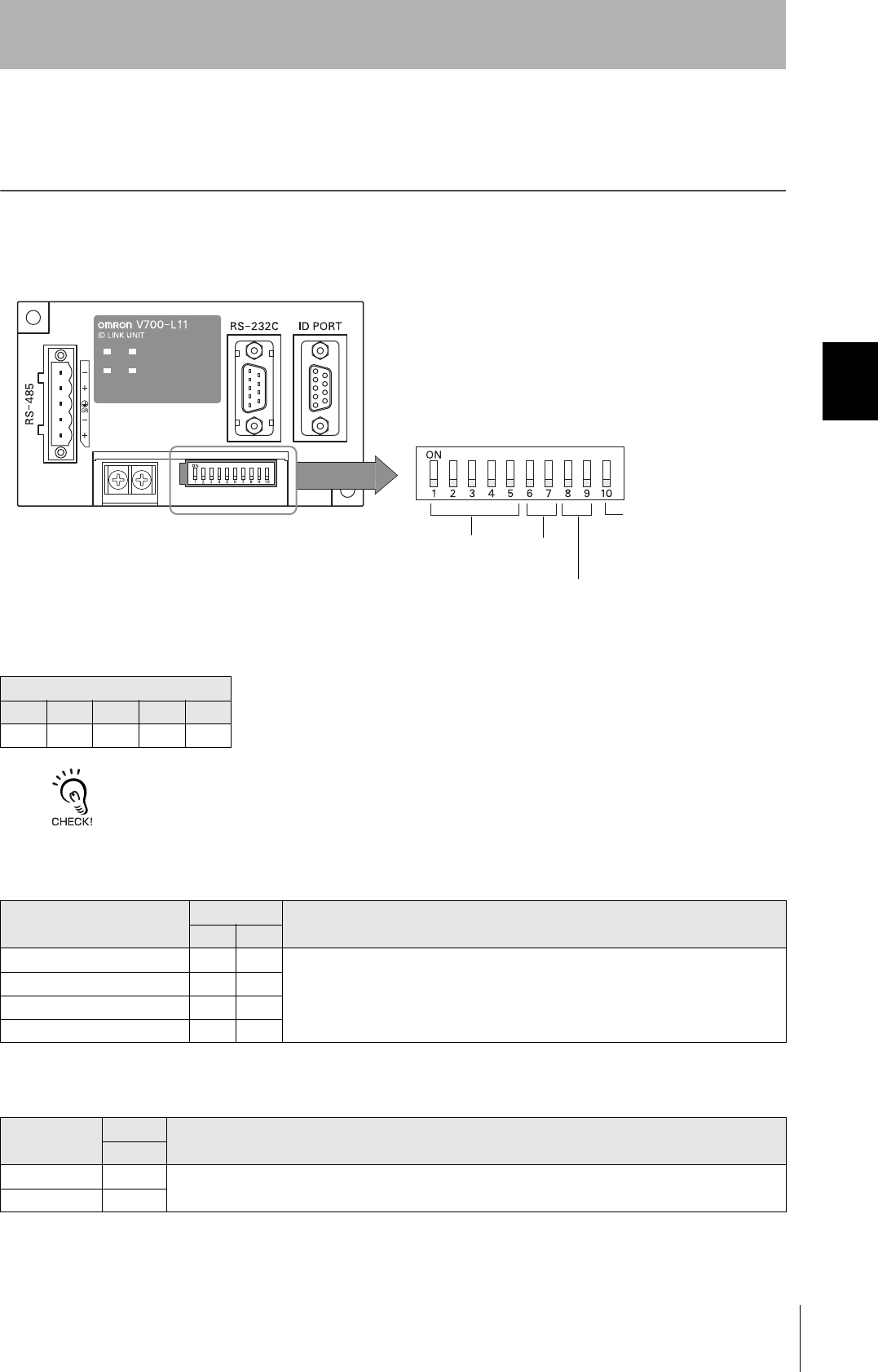
63
CIDRW System
User’s Manual
SECTION 3
Setting the Communications Conditions for Link Units
SECTION 3
Preparing for Communications
Setting the Communications Conditions for Link
Units
Set the communications conditions by setting the DIP switches.
The node numbers for Link Units are fixed. Check that DIP switches 1to 5 are all ON.
Node No. (fixed)
DIP-SW
1 2 3 4 5
ON ON ON ON ON
Baud Rate
Option DIP-SW Description
6 7
38400 bps ON ON Use a consistent baud rate setting within the same system configuration.
19200 bps OFF ON
9600 bps (default setting) OFF OFF
4800 bps ON OFF
RS-485 Terminator
Option DIP-SW Description
10
Invalid OFF Set ON.
Valid ON
Node No. Baud rate
Always OFF
(Not used in this CIDRW system)
RS-485 terminator
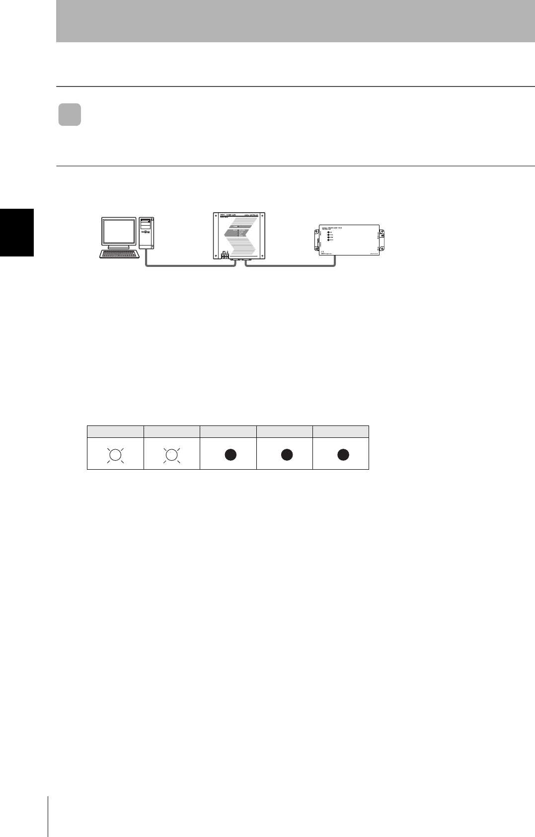
64
SECTION 3
Communications Test
CIDRW System
User’s Manual
SECTION 3
Preparing for Communications
Communications Test
Communications Test with the Host Device
Check if the host device, CIDRW Controller, and Amplifier Units are correctly connected.
■When SECS Is Used
• Connection between host device and CIDRW Controller
Send Are You There Request message "S1, F1" from the host device.
If it is correctly connected, On Line Data “S1, F2” will be sent from the CIDRW Controller.
• Connection between the CIDRW Controller and Amplifier Unit
The connection between the CIDRW Controller and Amplifier Unit is checked automatically. If they are
connected correctly, the operation indicators on the CIDRW Controller light in the manner shown
below.
POWER OPERATING ALARMS BUSY ERROR
CIDRW ControllerHost Amplifier Unit
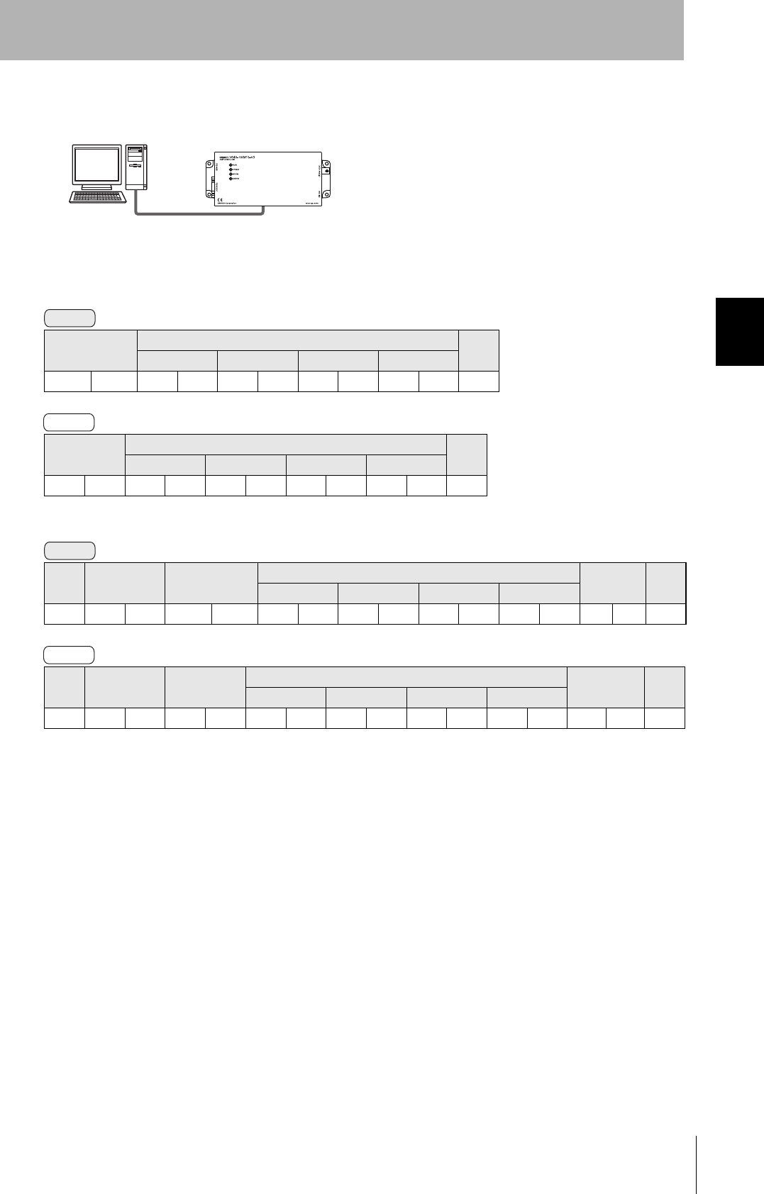
65
CIDRW System
User’s Manual
SECTION 3
Communications Test
SECTION 3
Preparing for Communications
■When SECS Is Not Used
Node No.1 is tested with the data 12345678.
• 1:1 Protocol
• 1:N Protocol
Command code Test data CR
Data 1 Data 2 Data 3 Data 4
1 0 123456780Dh
Response
code
Test data CR
Data 1 Data 2 Data 3 Data 4
00123456780Dh
SOH Node No. Command code Test data FCS CR
Data 1 Data 2 Data 3 Data 4
01h01 1 0 12345678080Dh
SOH Node No. Response
code
Test data FCS CR
Data 1 Data 2 Data 3 Data 4
01h010012345678090Dh
Amplifier UnitHost
Command
Response
Command
Response

66
SECTION 3
Communications Test
CIDRW System
User’s Manual
SECTION 3
Preparing for Communications
Communications Test between ID Tags and CIDRW System
Send a command from the host device and check that normal communications with the ID Tag is pos-
sible.
■When SECS Is Used
• Read ID
The host device sends a Read ID Request message to the CIDRW Controller for Head 1. The CIDRW
Head 1 reads the ID, and the CIDRW Controller returns the ID to the host device.
• Read Data
The host device sends a Read Data Request message to the CIDRW Controller for Head 1, DataSeg
S01 and Datalength 8. The CIDRW Head 1 reads the data, and the CIDRW Controller returns the data
to the host device.
CIDRW Controller Host
S18, F9 Read ID Request
Target ID="00"
S18, F10 Read ID Data
MID="XYZ00001"
CIDRW Controller Host
S18, F5 Read Request
Target ID="01"
Dataseg="S01"
Datalength="8"
S18,F6 Read Data
Data="yyyyyyyy"
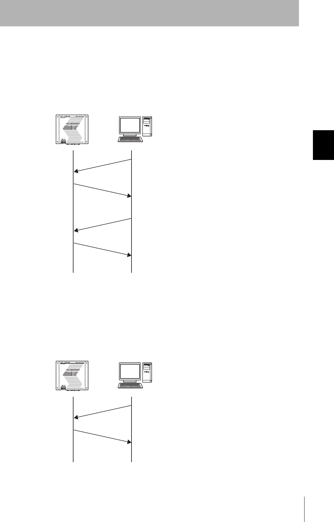
67
CIDRW System
User’s Manual
SECTION 3
Communications Test
SECTION 3
Preparing for Communications
• Write ID
(1) The CIDRW Controller is in IDLE. The host device requests the CIDRW Controller change its oper-
ational status to MAINTENANCE.
(2) The CIDRW Controller changes to MAINTENANCE and replies that it has changed state.
(3) The host device sends a Write ID Request message to the CIDRW Controller for Head 1. The
CIDRW Head 1 writes ID, and the CIDRW Controller returns the ID to the host devices.
• Write Data
The host device sends a Write Data Request message to the CIDRW Controller for Head 1 and Data-
Seg S02. The CIDRW Head 1 writes the data, and the CIDRW Controller returns the results to the host
device.
CIDRW Controller Host
S18, F13 SubSystem Command Request
Target ID="01"
CPVAL="MT"
S18, F14 SubSystem Command Acknowledge
SSACK="NO"
S18, F11 Write ID
Target ID="01"
MID="ABC"
S18, F12 Write ID Data
SSACK="NO"
CIDRW Controller Host
S18, F7 Write ID Request
Target ID="01"
Dataseg="S02"
Data="xxxxxx"
S18, F8 Write Data Acknowledge
SSACK="NO"
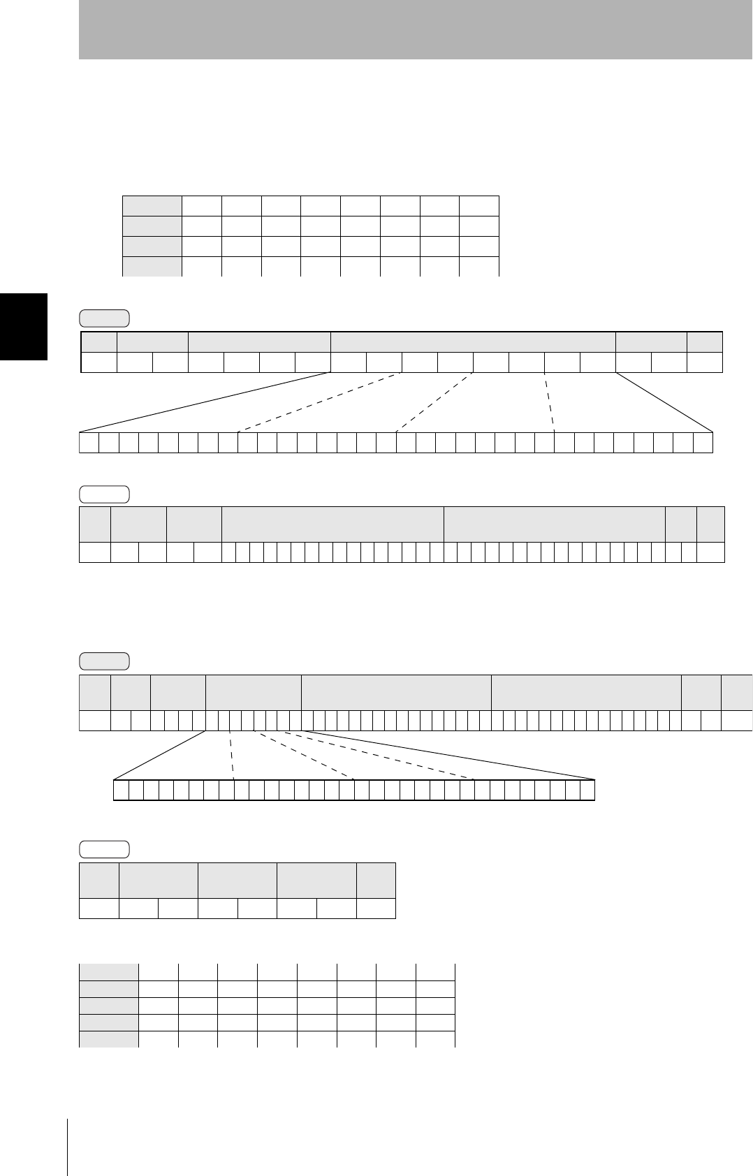
68
SECTION 3
Communications Test
CIDRW System
User’s Manual
SECTION 3
Preparing for Communications
■When SECS Is Not Used
• Read
Reading the page 1 and page 3 data of node No.1:
•Write
Writing data to page 8 and page 10 of node No.1:
The ID Tag status on normal completion is as shown below:
Data content of the ID Tag
Page 1 12h 34h 56h 78h 90h 12h 34h 56h
Page 2
Page 3 11h 22h 33h 44h 55h 66h 77h 88h
Page 4
SOH Node No. Response
code Page 1 Page 3 FCS CR
01h010012345678901234561122334455667788070Dh
SOH Node No. Response
code FCS CR
01h0100010Dh
Page 8 11h 22h 33h 44h 55h 66h 77h 88h
Page 9
Page 10 01h 23h 45h 67h 89h ABh CDh EFh
Command
00000000000000000000000000010100
Binary notation
SOH Node No. Command code Page designation FCS CR
01h01010000000014050Dh
Response
Command
00000000000000000000101000000000
SOH Node
No.
Command
code Page designation Data of page 8 Data of page 10 FCS CR
01h 0 1 0 2 0 000000A0011223344556677880123456789ABCDEF 7 4 0Dh
Binary notation
Response