Omron V640HAM11L Carrier ID Reader/Writer (RFID) User Manual Z308 E1 01
Omron Corporation Carrier ID Reader/Writer (RFID) Z308 E1 01
Omron >
Contents
- 1. User manual1(L)
- 2. User manual2(L)
- 3. User manual1(L-ETN)
- 4. User manual2(L-ETN)
User manual2(L-ETN)

SECTION 6
Troubleshooting
69
CIDRW System
User’s Manual
SECTION 6
Troubleshooting
Troubleshooting 70
70
SECTION 6
Troubleshooting
CIDRW System
User’s Manual
SECTION 6
Troubleshooting
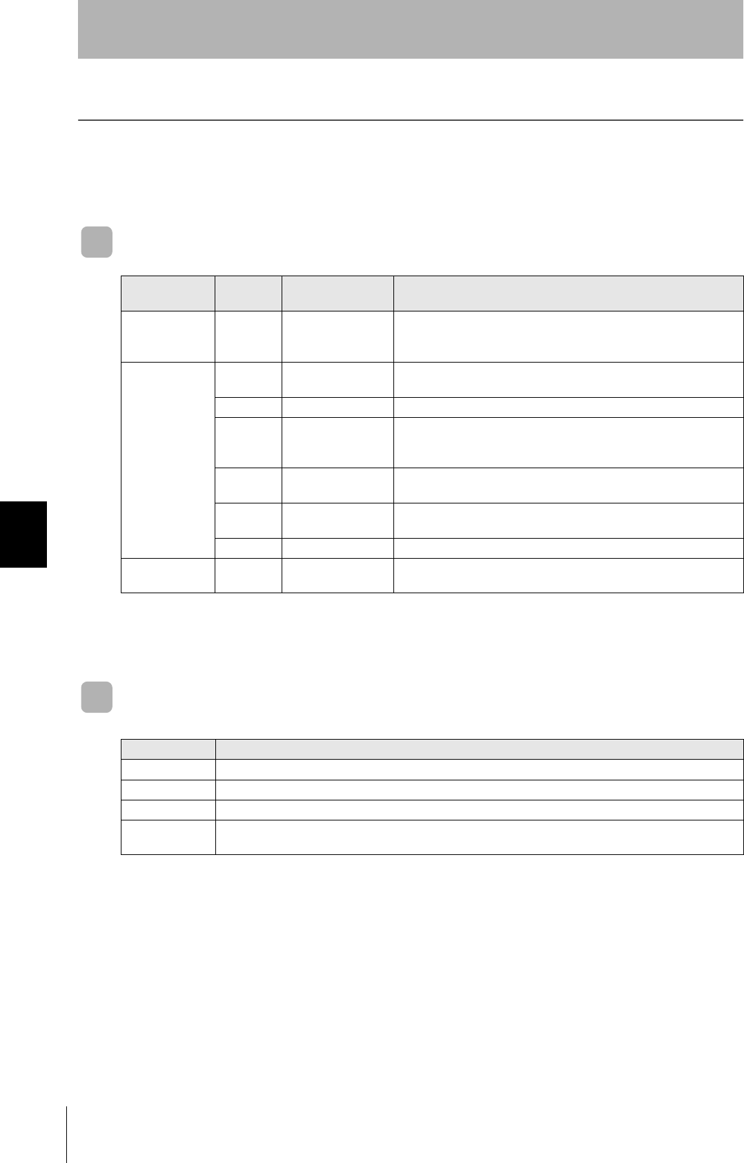
Troubleshooting
Errors are indicated by the presence or absence of a response to an Amplifier Unit command, and by the
indicators.
List of Error Messages
Amplifier Unit Indicators
Type Response
code Name Description
Host communi-
cations error
14 Format error There is a mistake in the command format. (For example, the com-
mand portion is undefined, or the page or address specification is
inappropriate.)
Communications
error between
the CIDRW Head
and ID Tag
70 Communications
error
Noise or another hindrance has occurred during communications with
an ID Tag, and communications cannot be completed normally.
71 Verification error Correct data cannot be written to an ID Tag.
72 No Tag error Either there is no ID Tag in front of the CIDRW Head, or the CIDRW
Head is unable to detect the ID Tag due to environmental factors (e.g.,
noise).
7B Outside write area
error
The ID Tag is at a position where reading is possible but writing is not,
so writing does not complete normally.
7E ID system error (1) The ID Tag is in a status where it cannot execute the command pro-
cessing.
7F ID system error (2) An inapplicable ID Tag has been used.
CPU hardware
error
9A Hardware error in
CPU
An error occurred when writing to EEPROM.
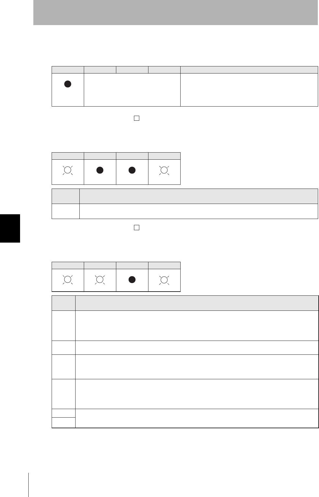
Name Indications
RUN (green) Turns ON when the Amplifier Unit is in normal operation.
COMM (orange) Turns ON during communications with the host device or during communications with an ID Tag.
NORM (green) Turns ON when the communications finish with no error.
ERROR (red) Turns ON when an error occurs during communications with the host device, or during communications
with an ID Tag.
CIDRW System
User’s Manual
SECTION 6
Troubleshooting
SECTION 6
Troubleshooting
71
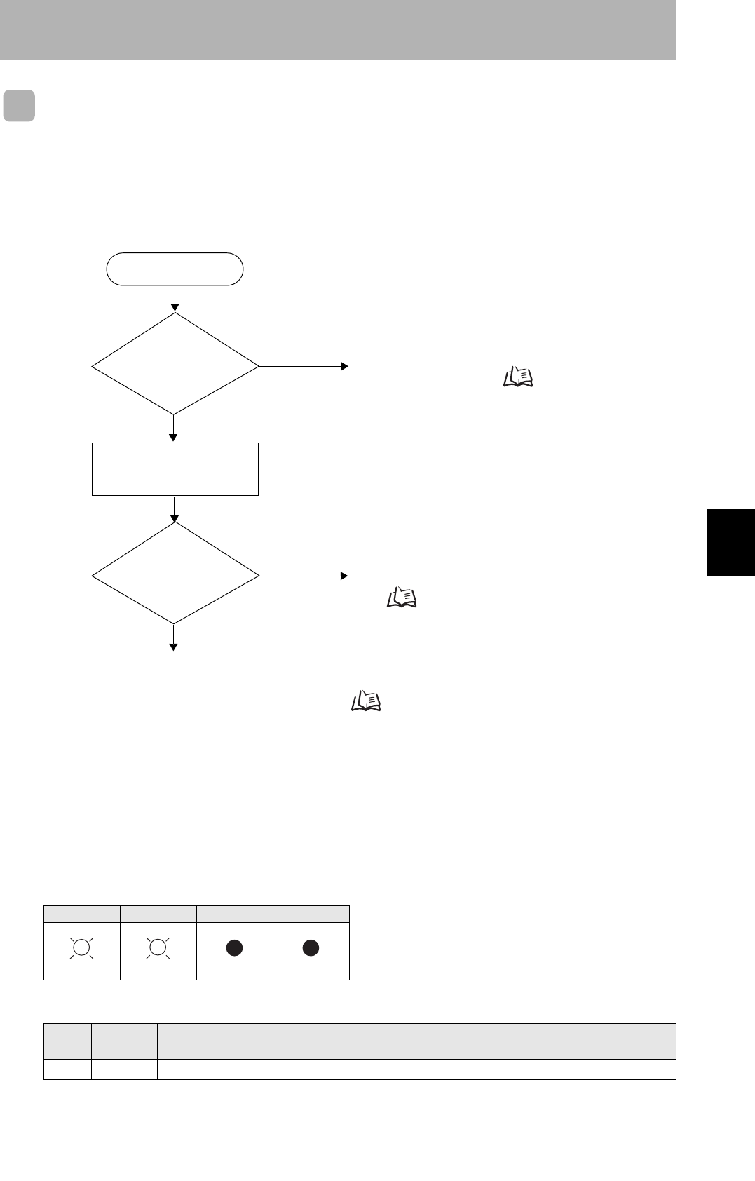
Operation Check Flowchart
■From Installation to Trial Operation
Errors are indicated by whether or not a response to the test command is received and by the status of
the Amplifier Unit indicators.
• If the Test Command Was Received Normally:
Indicators
RUN COMM NORM ERROR
Response Code for the Response
Type Response
code Function
Normal 00 The command was received normally.
Error occurrence
Test command transmission
RUN indicator
OFF?
No
Yes An error has occurred at the Amplifier Unit.
Amplifier Unit error Refer to page 72.
Check if the Amplifier Unit settings are correct.
If There Is No Response to the Command: Refer to page 72.
Response received? Yes Check the nature of the response.
If there is a response to the command
Refer to page 72.
No
(Lights once)
72
SECTION 6
Troubleshooting
CIDRW System
User’s Manual
SECTION 6
Troubleshooting
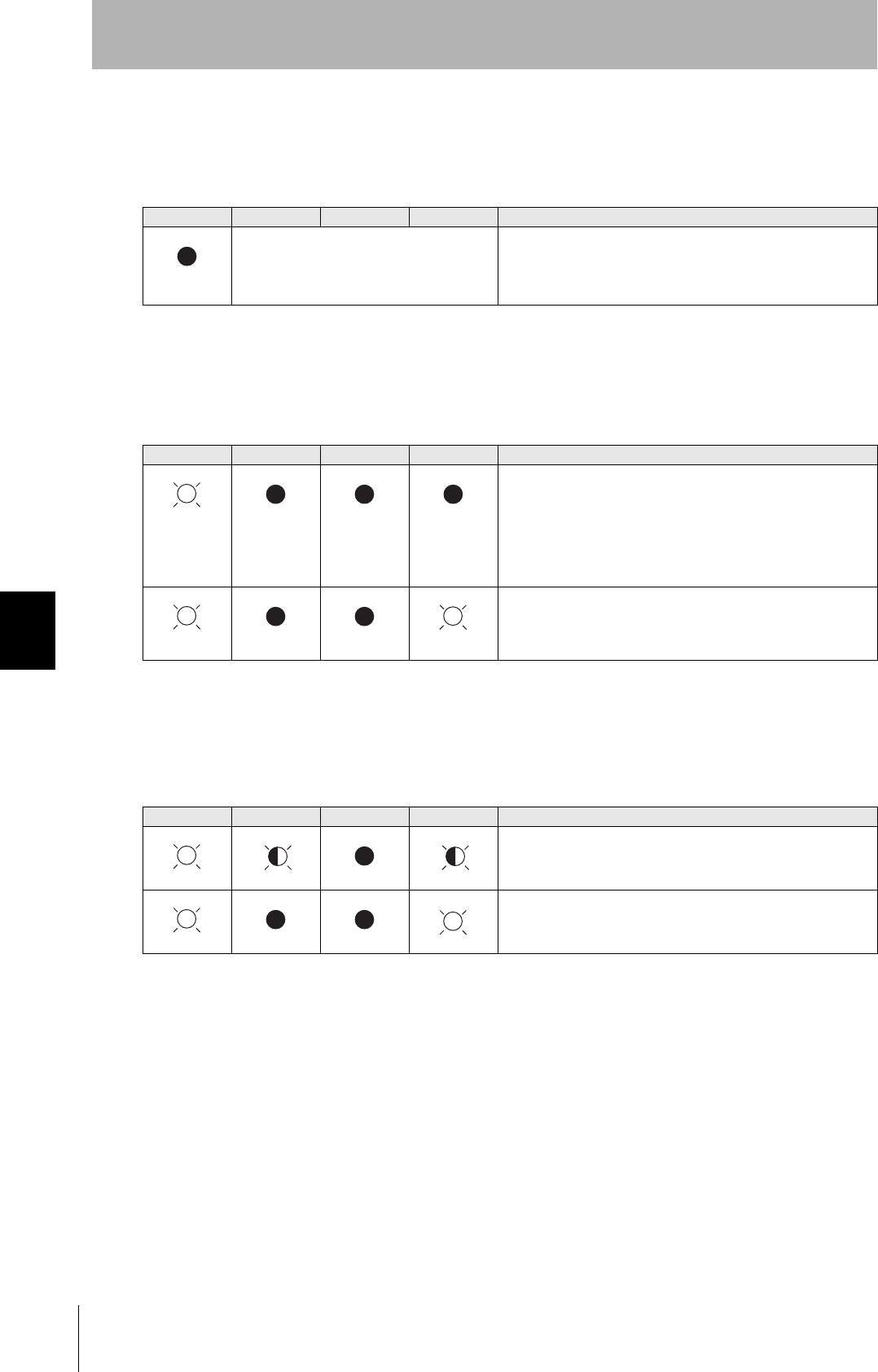
• Amplifier Unit Error
Check the status of the indicators after transmission of the test command.
After taking appropriate corrective action, restart the Amplifier Unit, send the test command again and
check again.
• If There Is No Response to the Command:
Check the status of the indicators after transmission of the test command.
After taking appropriate corrective action, restart the Amplifier Unit, send the test command again and
check again.
• If There Is a Response to the Command:
Check the status of the indicators after transmission of the test command.
After taking appropriate corrective action, restart the Amplifier Unit, send the test command again and
check again.
RUN COMM NORM ERROR Main check points
—
(If RUN is OFF, the status of the other indica-
tors can be ignored.)
• Influence of background noise (change installation position)
• Amplifier Unit power supply
If the error cannot be resolved after checking, the Amplifier Unit
may be damaged.
RUN COMM NORM ERROR Main check points
• Amplifier Unit baud rate settings
• Node numbers of the Amplifier Units (do not match the node
number in the test command)
• Connection and wiring of the cable between the host device
and Amplifier Unit
• Routing of each cable (influence of background noise)
If the error cannot be resolved after checking, the Amplifier Unit
may be damaged.
• Amplifier Unit baud rate settings
• Connection and wiring of the cable between the host device
and Amplifier Unit
• Routing of the cables (influence of background noise)
RUN COMM NORM ERROR Main check points
• Node numbers of the Amplifier Units (The same number is set
for more than one Unit)
If the error cannot be resolved after checking, the Amplifier
Unit may be damaged.
There is a mistake in the command format (number of charac-
ters, character code, etc.).
(Lights once)
(Lights once)
CIDRW System
User’s Manual
SECTION 6
Troubleshooting
SECTION 6
Troubleshooting
73
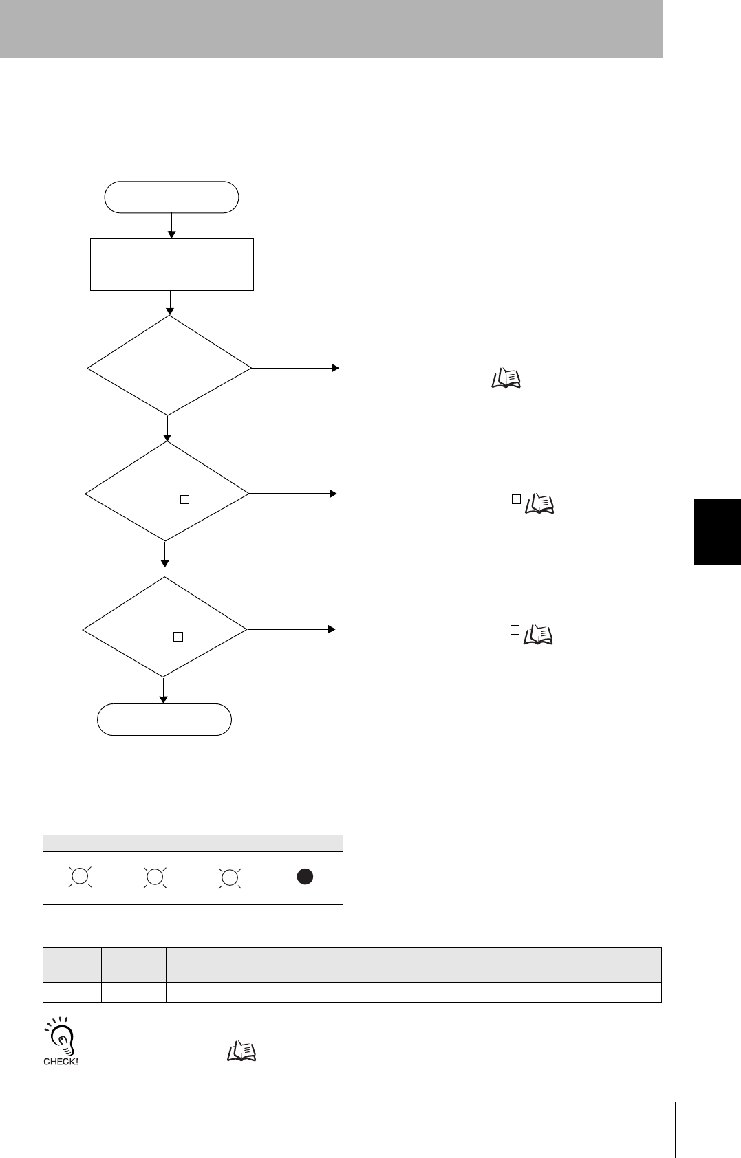
■From Trial Operation to Communications
Errors are indicated by the status of the indicators after transmission of the write command, and by the
response code of the response.
• If the ID Tag Was Processed Normally:
If there is no response to the write command, refer to the From Installation to Trial Operation,
Operation Check Flowchart. Refer to page 71.
Indicators
RUN COMM NORM ERROR
Response Code for the Response
Type Response
code Function
Normal 00 The ID Tag was processed normally.
Error occurrence
Is the response
code 1 ?
No
Yes Check the command format.
If the response code is 1 Refer to page 74.
Yes Communications with the ID Tag has failed.
If the response code is 7 Refer to page 74.
Write command sent
RUN indicator
OFF?
No
Yes An error has occurred at the Amplifier Unit.
Amplifier Unit error Refer to page 74.
Is the response
code 7 ?
Communications OK
No
(Lights once)
(Lights once)
74
SECTION 6
Troubleshooting
CIDRW System
User’s Manual
SECTION 6
Troubleshooting
• Amplifier Unit Error
Check the status of the indicators after transmission of the command. After taking appropriate correc-
tive action, send the write command again and check again.
• If the Response Code is 1 :
There is a host device communications error.
Check the status of the indicators and the response code of the response after transmission of the
command. After taking appropriate corrective action, send the write command again and check again.
• If the Response Code is 7 :
There is a communications error in communications between the CIDRW Head and ID Tag.
Check the status of the indicators and the response code of the response after transmission of the
command. After taking appropriate corrective action, send the write command again and check again.
* The ID Tag has a lock function, but the Amplifier Unit has no function for locking an ID Tag.
RUN COMM NORM ERROR Main check points
—
(If RUN is OFF, the status of the other indica-
tors can be ignored.)
• Influence of background noise (Change installation position)
• Amplifier Unit power supply
If the error cannot be resolved by checking the two points above,
the Amplifier Unit may be damaged.
RUN COMM NORM ERROR
Response
code Main check points
14 Command format
(Command code, page designation, address designation, processed data volume, etc.)
RUN COMM NORM ERROR
Response
code Main check points
70
• Background noise levels of the CIDRW Head (Check the surroundings with the environmental noise level measurement
function)
• Distance to another CIDRW Head
• Influence of background noise (Change installation position)
If the error cannot be resolved after checking, the Amplifier Unit may be damaged.
71 • ID Tag overwrite life (Replace the ID Tag)
• Environment of use of the ID Tags (ID Tag breakage due to use in unanticipated ways)
72 • Connection to the CIDRW Head
• Distance between the ID Tag and CIDRW Head
• CIDRW Head background noise levels (Check the surroundings with the environmental noise level measurement function)
• Distance to another CIDRW Head
7B • Distance between the ID Tag and CIDRW Head
• Background noise levels of the CIDRW Head (Check the surroundings with the environmental noise level measurement
function)
• Distance to another CIDRW Head
• Influence of background noise (Change installation position)
7E • Type/specifications of the ID Tags used
• Settings of the ID Tags used (The ID Tag lock function is used.*)
• Environment of use of the ID Tags (ID Tag breakage due to use in unanticipated ways)
7F
(Lights once)
(Lights once)
(Lights once)

SECTION 7
Appendix
75
CIDRW System
User’s Manual
SECTION 7
Appendix
Specifications and Dimensions 76
Connection Examples 80
Characteristic Data According to Conditions of Use 81
ID Tag Memory Maps 111
Regular Inspection 112
ASCII Code Table 113
Protective Construction 114
76
SECTION 7
Specifications and Dimensions
CIDRW System
User’s Manual
SECTION 7
Appendix
Specifications and Dimensions
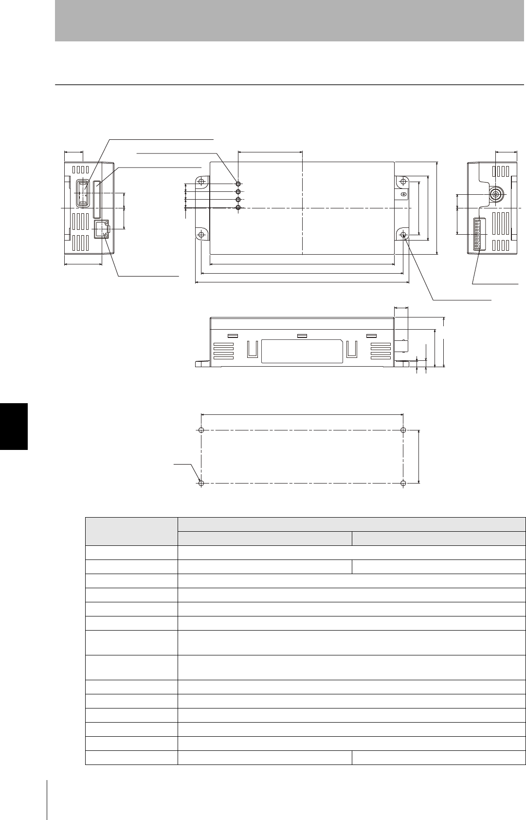
Amplifier Units
V640-HAM11-ETN and V640-HAM11-L-ETN
■General Specifications
Item Specifications
V640-HAM11-ETN V640-HAM11-L-ETN
Power supply voltage 24 VDC +10% -15%
Current consumption 150 mA max. 400 mA max.
Ambient temperature Operating: 0 to +40°C Storage: -15 to +65°C (with no icing)
Ambient humidity Operating/Storage: 35% to 85% (with no condensation)
Degree of protection IP20 (IEC60529 standard)
Insulation resistance 20 MΩ min. between power supply terminals and the frame ground terminal (100 VDC M)
Dielectric strength Leak current not to exceed 5 mA on application of 1000 VAC (50/60 Hz for 1 minute) between both
power supply terminals and the frame ground terminal
Vibration resistance Frequency: 10 to 150 Hz; double amplitude: 0.20 mm; acceleration: 15 m/s2 for
8 minutes, 10 times each in X, Y, and Z directions
Shock resistance Shock of 150 m/s2 in X, Y, and Z directions, 3 times each for 18 repetitions
Ground Ground to 100 Ω or less.
Case material PC/ABS resin
Shape 80×185×43 mm (W×D×H)
Weight Approx. 250 g
CIDRW Head V640-HS61 V640-HS62
175±0.5
160
175
185
55.5
46
56
80
6.86.86.80.6
(11.5)
(32.5)
43
5
(5.7)
(13)
(18)
(31.95)
(15.8)
(12)
(18.2)
(22.5)
4-M4
46
±
0.5
DIP switch
(Unit: mm)
Mounting dimensions
Four, 4.5-dia. holes
DC power supply connector
MAC address label
Ethernet connector
Four operation indicators

CIDRW System
User’s Manual
SECTION 7
Specifications and Dimensions
SECTION 7
Appendix
77
■Host Communications Specifications
Access to an Amplifier Unit is possible from only one host device at a time. If a host device (A) is connected to an Ampli-
fier Unit and another host device (B) connects to the Amplifier Unit, the connection between host device A and the
Amplifier Unit will be automatically broken and host device B will have the control right.
Communications with the ID Tag will be aborted if the Ethernet cable is disconnected or the connection is broken while
the Amplifier Unit is communicating with an ID Tag.
Item Description
Compliant standards 10Base-T and 100Base-TX
Protocol TCP/IP
Applicable port TCP/IP: port 7090
MTU 1,500 bytes
78
SECTION 7
Specifications and Dimensions
CIDRW System
User’s Manual
SECTION 7
Appendix
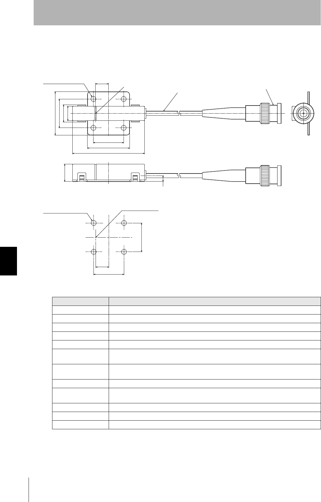
CIDRW Heads
V640-HS61
Item Specifications
Transmission frequency 134 kHz
Ambient temperature Operating: 0 to +40°C Storage: -15 to +65°C (with no icing)
Ambient humidity Operating/Storage: 35% to 85% (with no condensation)
Degree of protection IP60 (IEC60529)
Insulation resistance 20 MΩ min. between all terminals and the case (100 VDC M)
Dielectric strength Leak current not to exceed 5 mA on application of 1000 VAC (50/60 Hz for 1 minute) between all
terminals and the case
Vibration resistance Frequency: 10 to 150 Hz; double amplitude: 0.20 mm; acceleration: 15 m/s2 for
8 minutes, 10 times each in X, Y, and Z directions
Shock resistance Shock of 150 m/s2 in X, Y, and Z directions, 3 times each for 18 repetitions
Casing material ABS/epoxy resin
Stainless steel mount
Weight Approx. 70 g
Cable length 2 m
Cable specification 3-mm-dia. coaxial cable
Coaxial cable 3.0 dia., standard length 2 m
(Unit: mm)
Connector
Antenna center
Antenna center
Mounting dimensions
Four M3 or 3.5-dia. holes
Four, 3.5-dia. holes
CIDRW System
User’s Manual
SECTION 7
Specifications and Dimensions
SECTION 7
Appendix
79
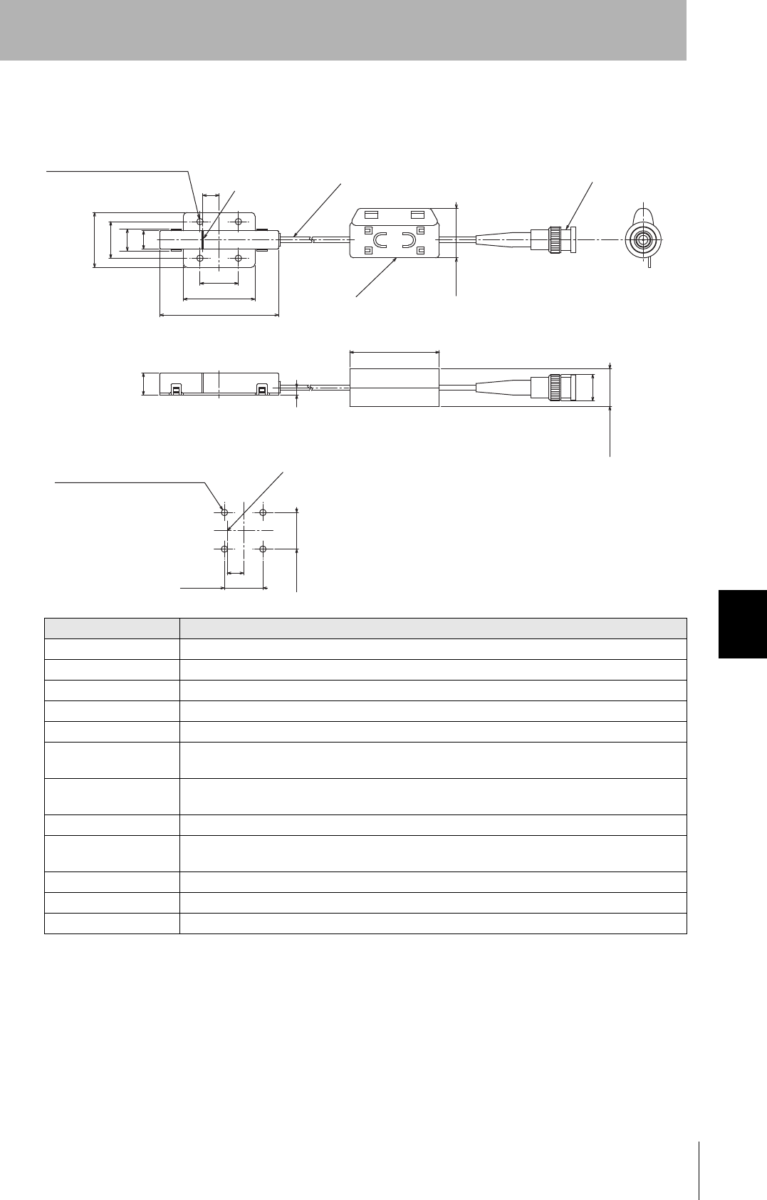
V640-HS62
Item Specifications
Transmission frequency 134 kHz
Ambient temperature Operating: 0 to +40°C Storage: -15 to +65°C (with no icing)
Ambient humidity Operating/Storage: 35% to 85% (with no condensation)
Degree of protection IP60 (IEC60529)
Insulation resistance 20 MΩ min. between all terminals and the case (100 VDC M)
Dielectric strength Leak current not to exceed 5 mA on application of 1000 VAC (50/60 Hz for 1 minute) between all
terminals and the case
Vibration resistance Frequency: 10 to 150 Hz; double amplitude: 0.20 mm; acceleration: 15 m/s2 for
8 minutes, 10 times each in X, Y, and Z directions
Shock resistance Shock of 150 m/s2 in X, Y, and Z directions, 3 times each for 18 repetitions
Casing material ABS/epoxy resin
Stainless steel mount
Weight Approx. 100 g
Cable length 1.9 m
Cable specification 3-mm-dia. coaxial cable
30
20
12
10
9
65
39.2
21
Max.28
12
4
49
14.5
Max.20.5
9
21±0.2
20±0.2
Ferrite core
(Unit: mm)
Connector
Coaxial cable, Dia.: 3.0, Length: 1.9 m
Center of coil
Mounting Hole Dimensions
Four M3 or 3.5-dia. holes
Four 3.5-dia. (mounting holes)
Center of coil
80
SECTION 7
Connection Examples
CIDRW System
User’s Manual
SECTION 7
Appendix
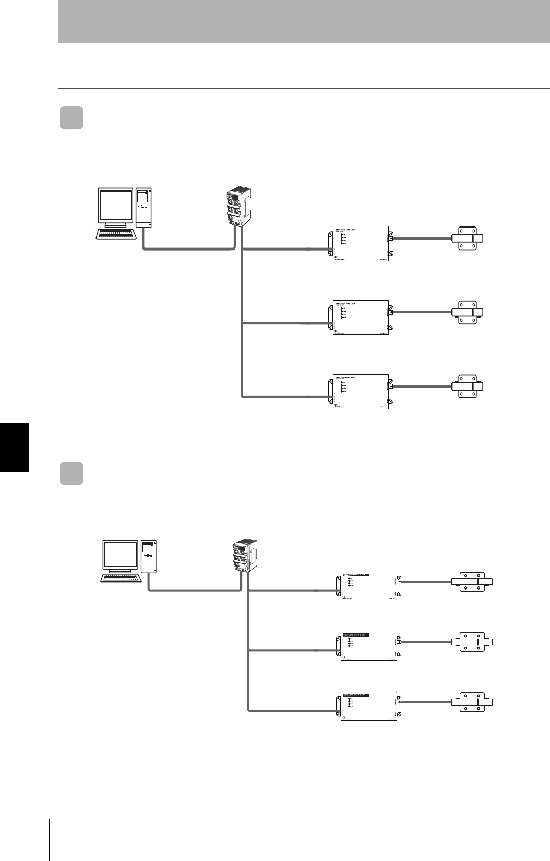
Connection Examples
V640-HAM11-ETN
Connect the host device and Amplifier Unit using a LAN cable.
V640-HAM11-L-ETN
Connect the host device and Amplifier Unit using a LAN cable.
Host device
Host computer,
device controller, etc.
CIDRW Head
V640-HS61
Amplifier Unit
V640-HAM11-ETN
Ethernet hub
LAN cable LAN cable
CIDRW Head
V640-HS61
Amplifier Unit
V640-HAM11-ETN
LAN cable
CIDRW Head
V640-HS61
Amplifier Unit
V640-HAM11-ETN
LAN cable
The Amplifier Unit controls the
CIDRW Head. Up to 256 Ampli-
fier Units can be connected.
The CIDRW Head is the
antenna. It reads and writes
carrier IDs and performs
other processing for ID Tags.
Host device
Host computer,
device controller, etc.
CIDRW Head
V640-HS62
Amplifier Unit
V640-HAM11-L-ETN
Ethernet hub
LAN cable LAN cable
CIDRW Head
V640-HS62
Amplifier Unit
V640-HAM11-L-ETN
LAN cable
CIDRW Head
V640-HS62
Amplifier Unit
V640-HAM11-L-ETN
LAN cable
The Amplifier Unit controls the
CIDRW Head. Up to 256 Ampli-
fier Units can be connected.
The CIDRW Head is the
antenna. It reads and writes
carrier IDs and performs
other processing for ID Tags.
CIDRW System
User’s Manual
SECTION 7
Characteristic Data According to Conditions of Use
SECTION 7
Appendix
81
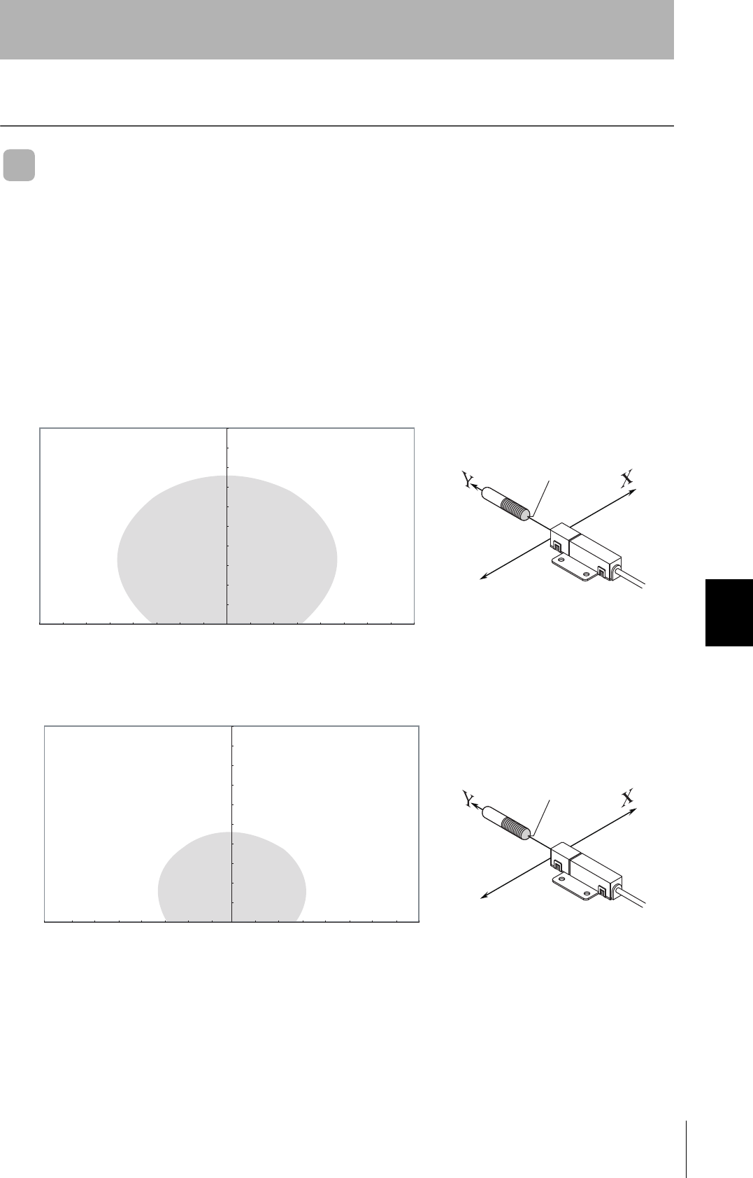
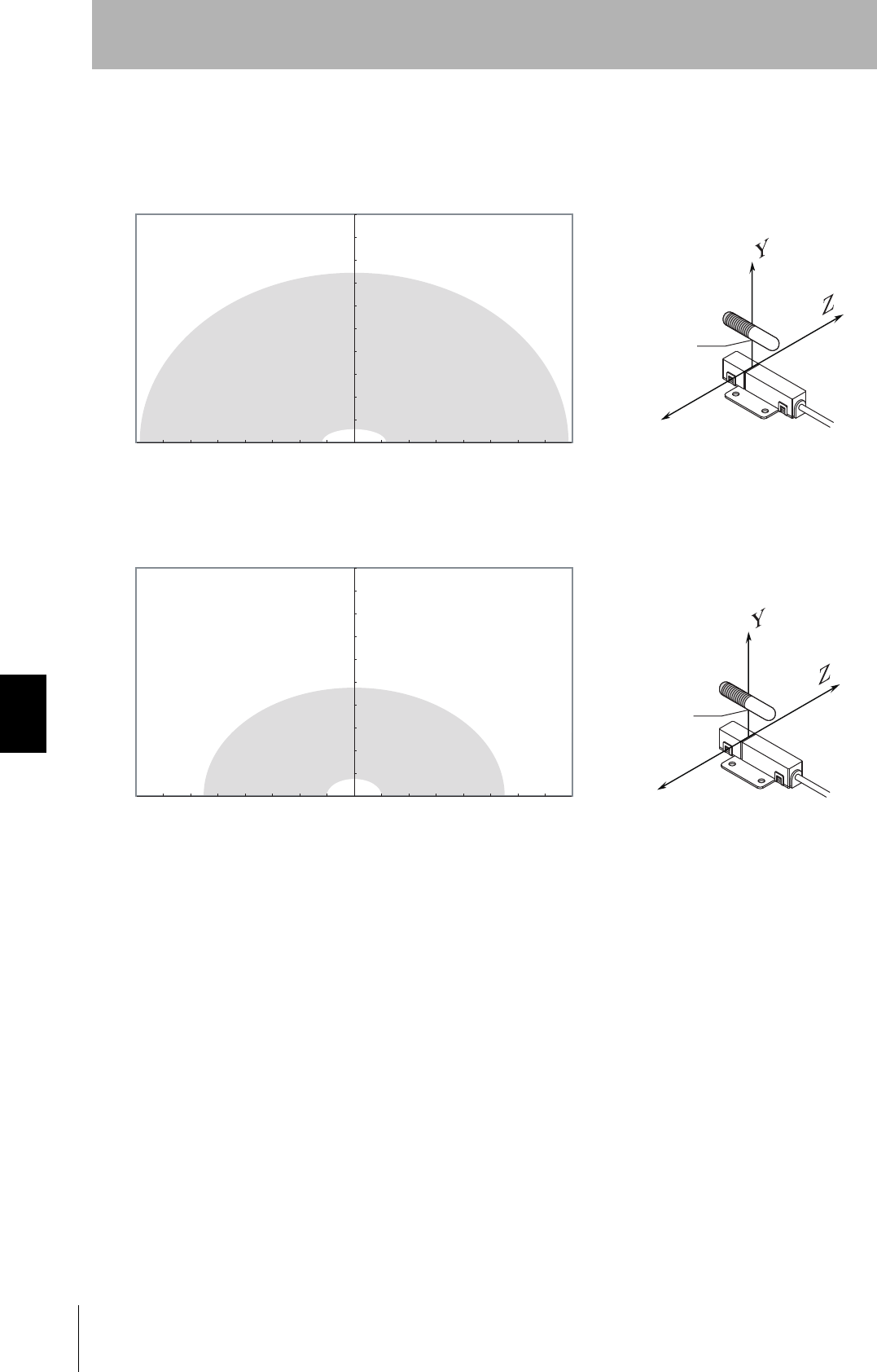
Characteristic Data According to Conditions of Use
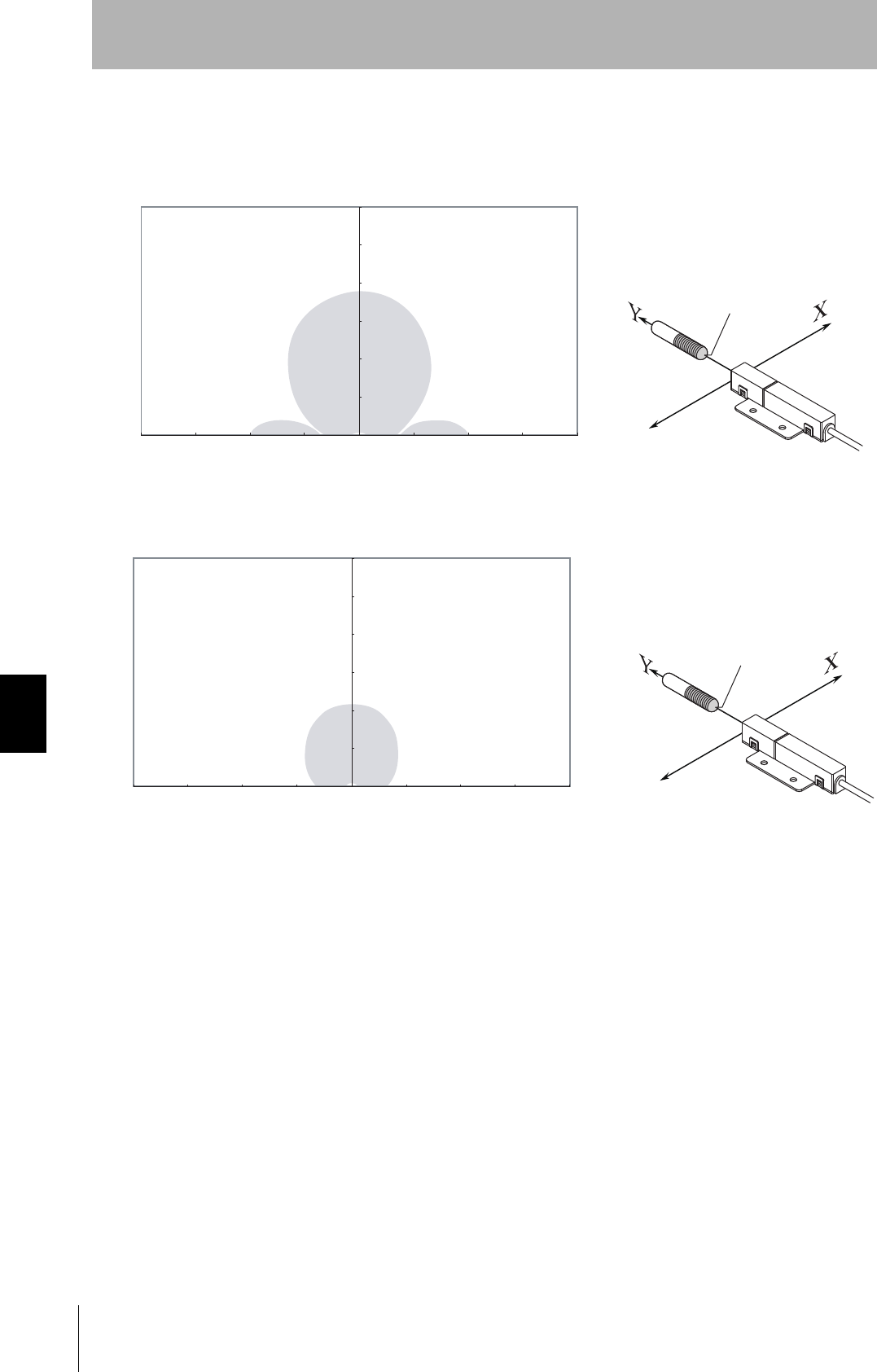
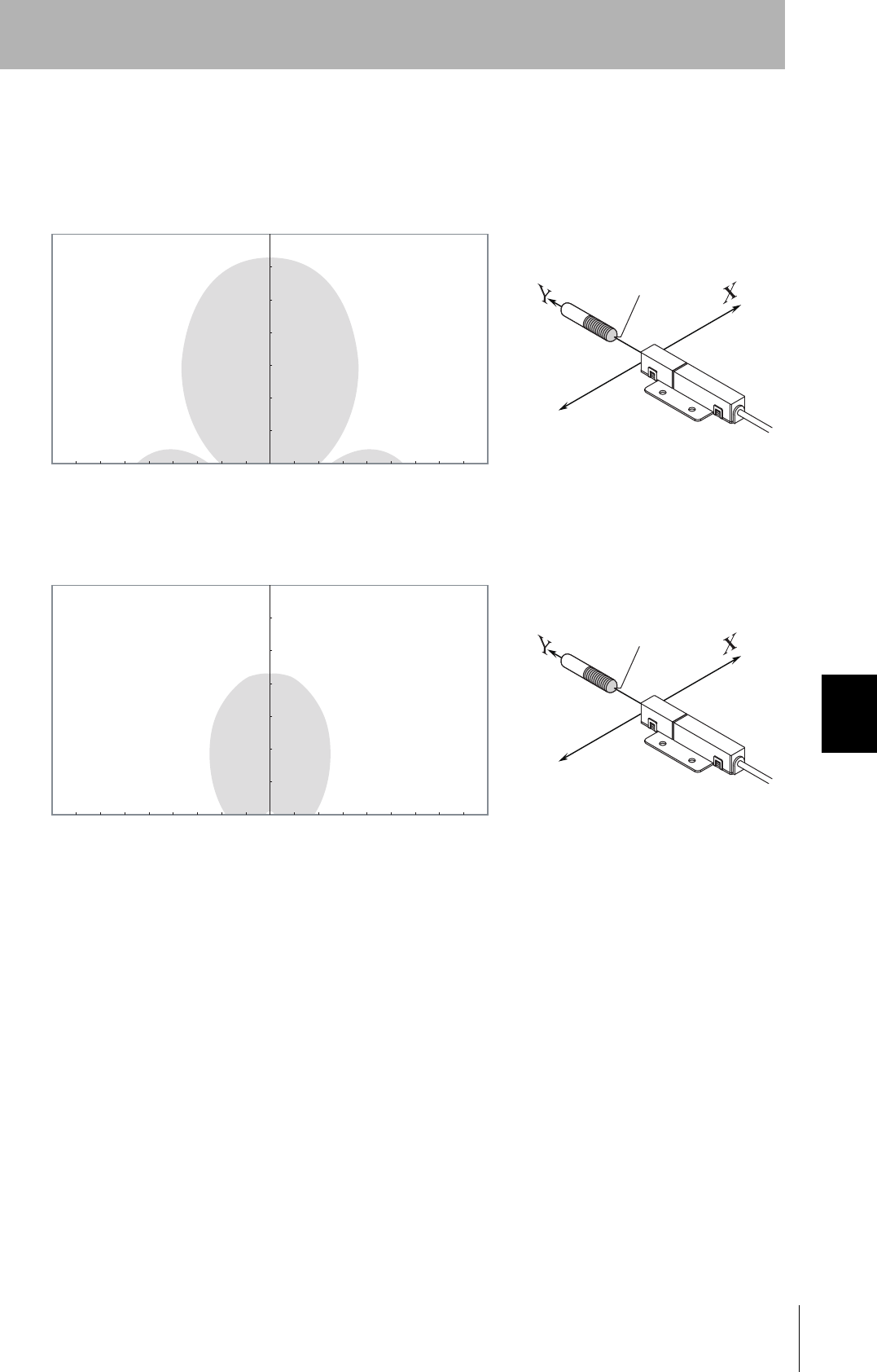
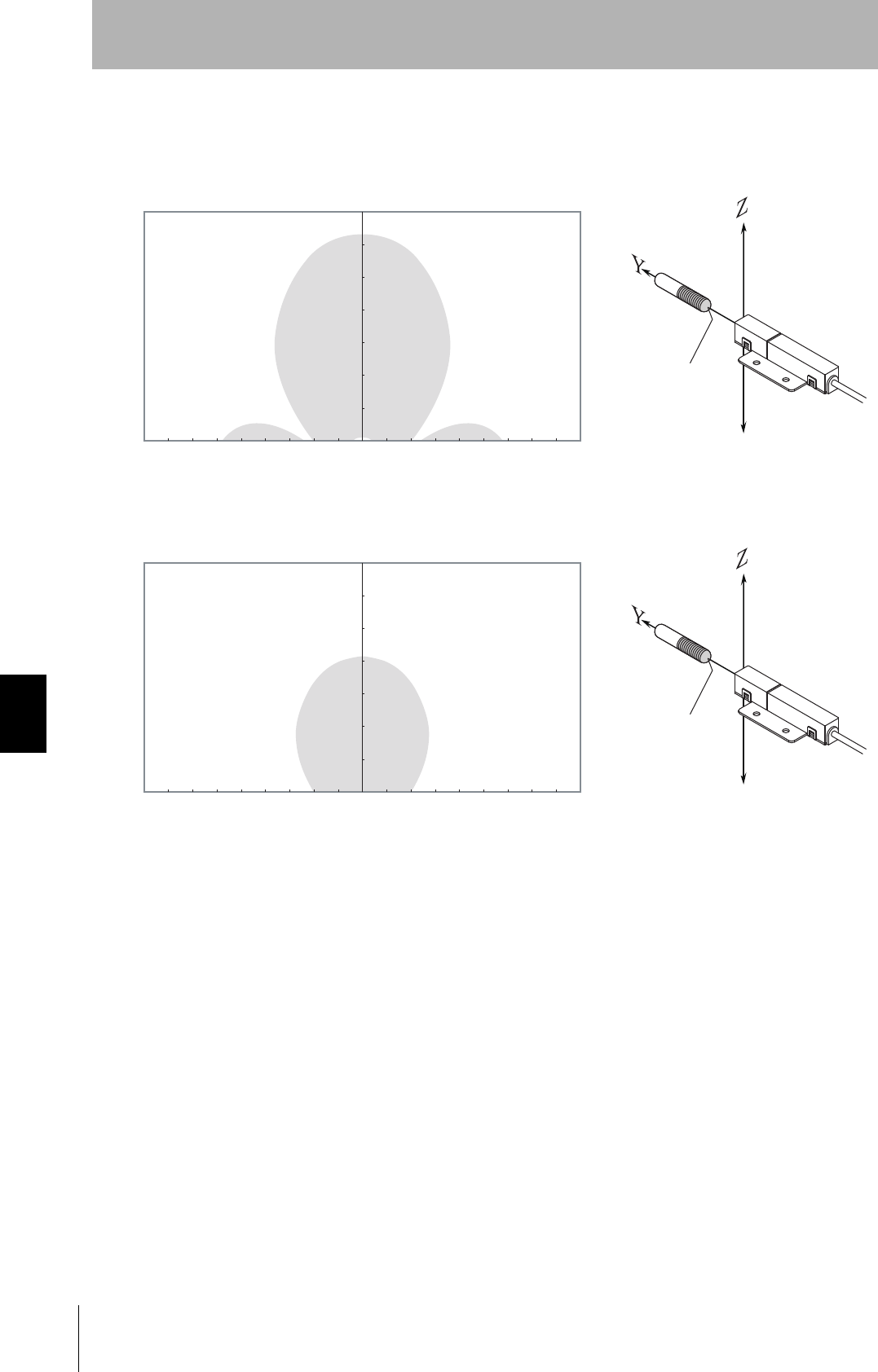
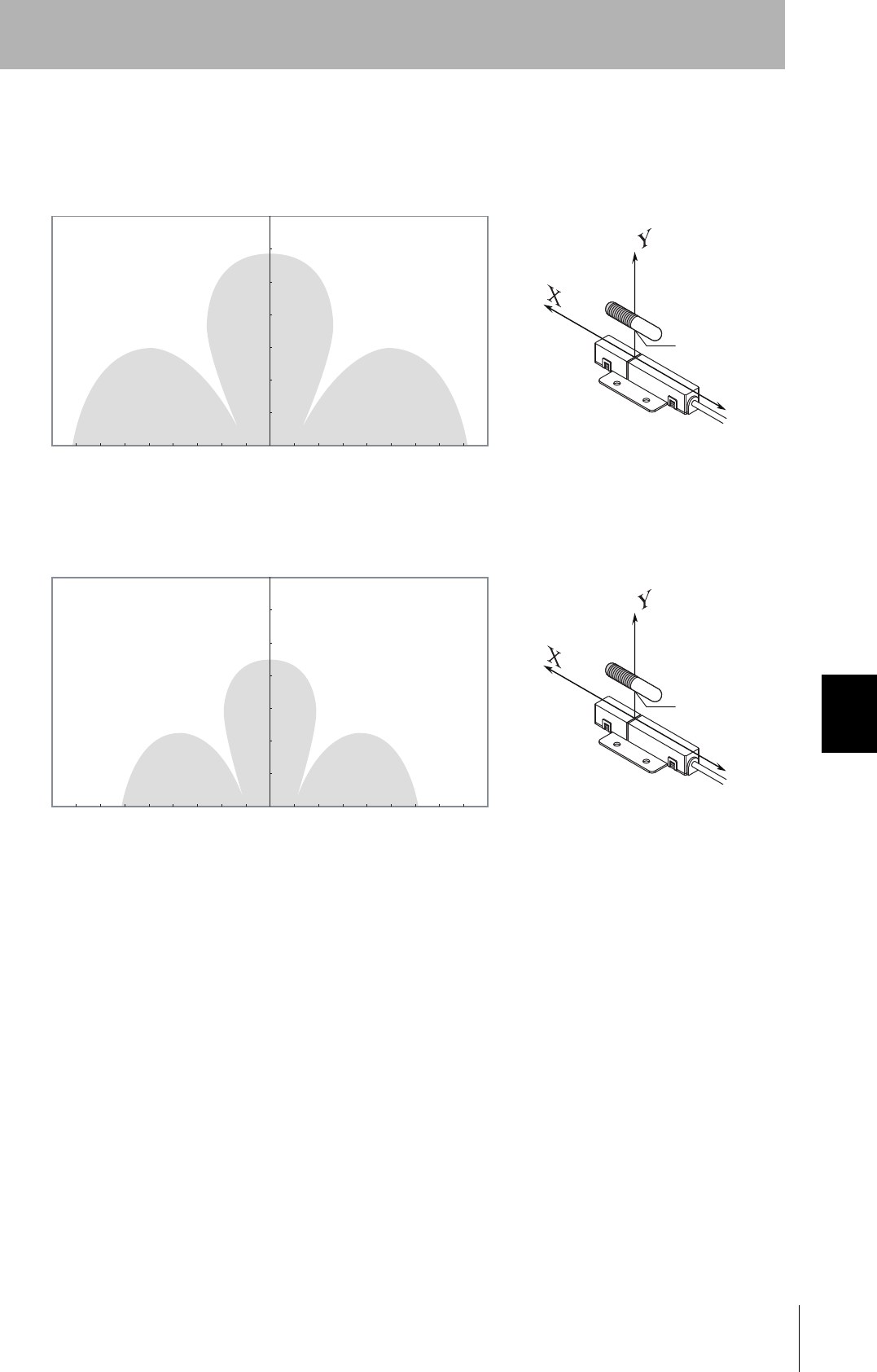
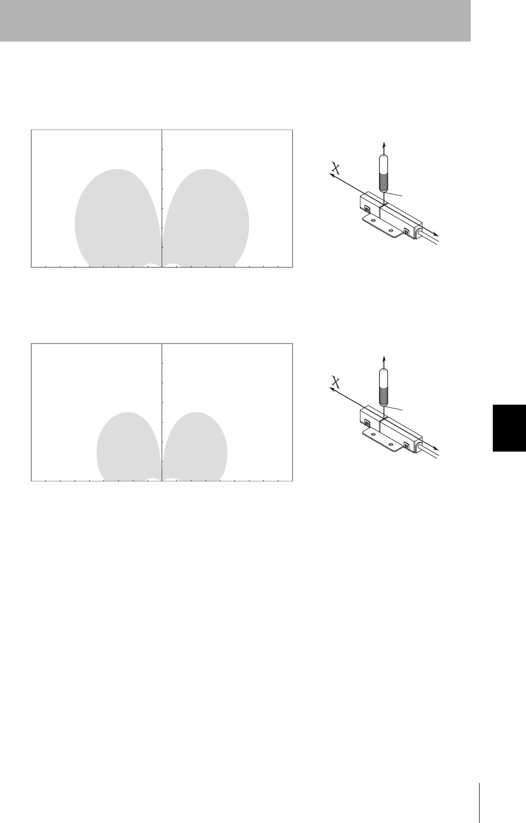
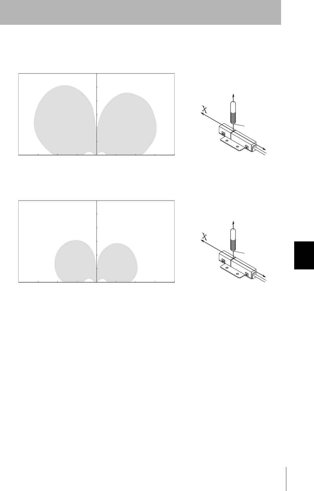
Maps of Communications Areas (Reference Only)
The figures given below for communications areas (communications distances) are reference values
only. The maps of communications areas will vary according to the ID Tags that you use, the back-
ground metals, the ambient noise, the effects of temperature and so on, and should be thoroughly con-
firmed on installation. The direction of the ID Tags will affect communications performance. Check the
direction of the coils in the ID Tags before using the ID Tags.
■V640-HAM11-ETN
• Coaxial Mounting (RI-TRP-DR2B)
• READ
• WRITE
0
10
20
30
40
50
60
70
80
90
100
-80 -70 -60 -50 -40 -30 -20 -10 0 10 20 30 40 50 60 70 80
Communications Area (READ)
Distance in Y direction (mm)
Distance in X direction (mm)
Measurement point
0
10
20
30
40
50
60
70
80
90
100
-80 -70 -60 -50 -40 -30 -20 -10 0 10 20 30 40 50 60 70 80
Communications Area (WRITE)
Distance in Y direction (mm)
Distance in X direction (mm)
Measurement point
82
SECTION 7
Characteristic Data According to Conditions of Use
CIDRW System
User’s Manual
SECTION 7
Appendix
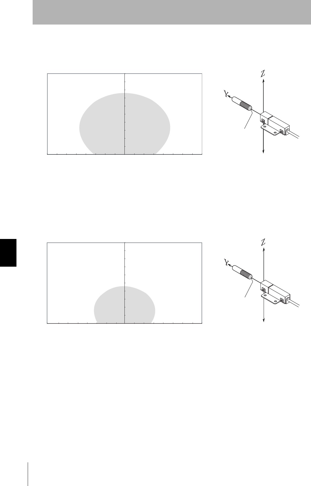
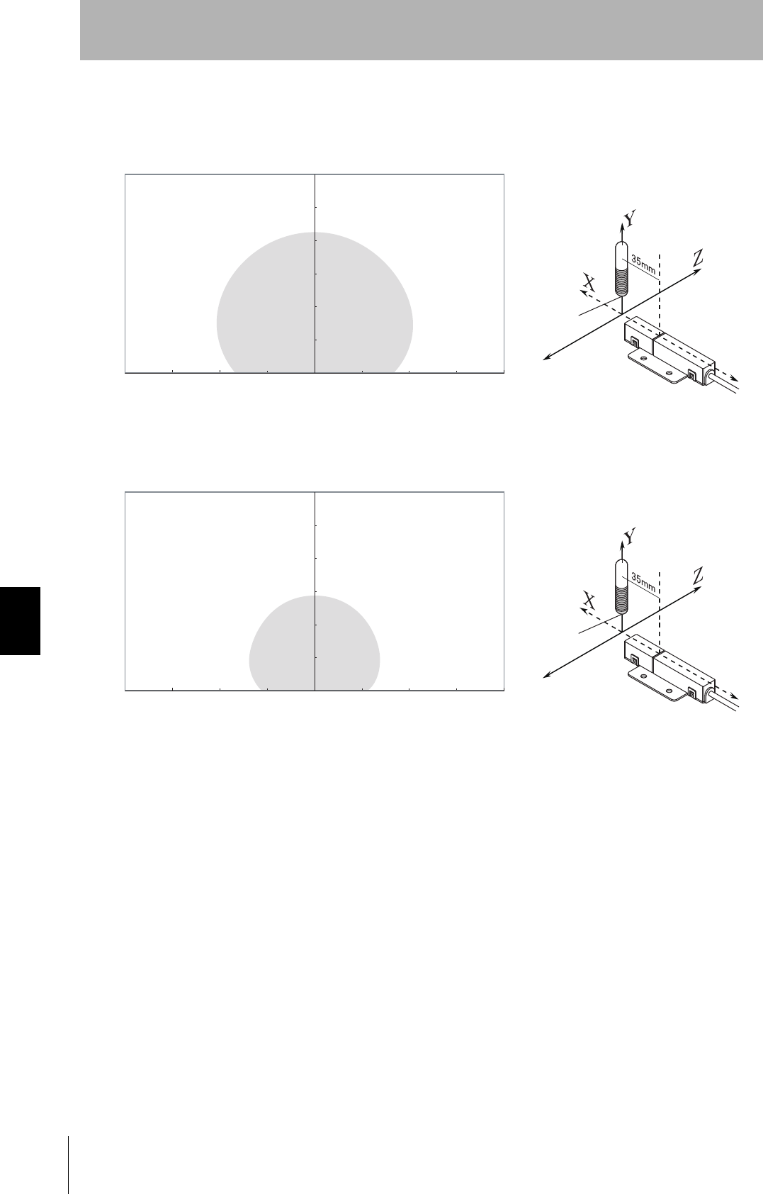
• Coaxial Mounting (RI-TRP-DR2B)
• READ
• WRITE
0
10
20
30
40
50
60
70
80
90
100
-80 -70 -60 -50 -40 -30 -20 -10 0 10 20 30 40 50 60 70 80
Communications Area (READ)
Distance in Z direction (mm)
Measurement point
Distance in Y direction (mm)
0
10
20
30
40
50
60
70
80
90
100
-80 -70 -60 -50 -40 -30 -20 -10 0 10 20 30 40 50 60 70 80
Communications Area (WRITE)
Distance in Z direction (mm)
Measurement point
Distance in Y direction (mm)
CIDRW System
User’s Manual
SECTION 7
Characteristic Data According to Conditions of Use
SECTION 7
Appendix
83
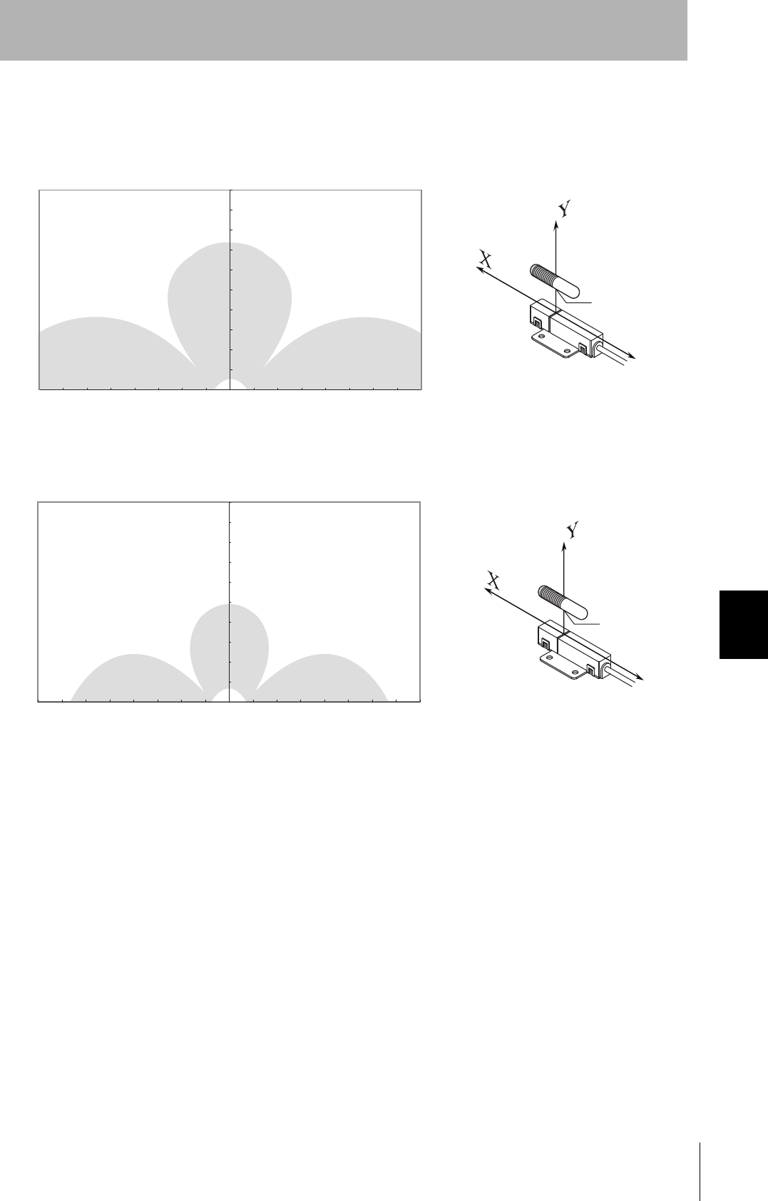
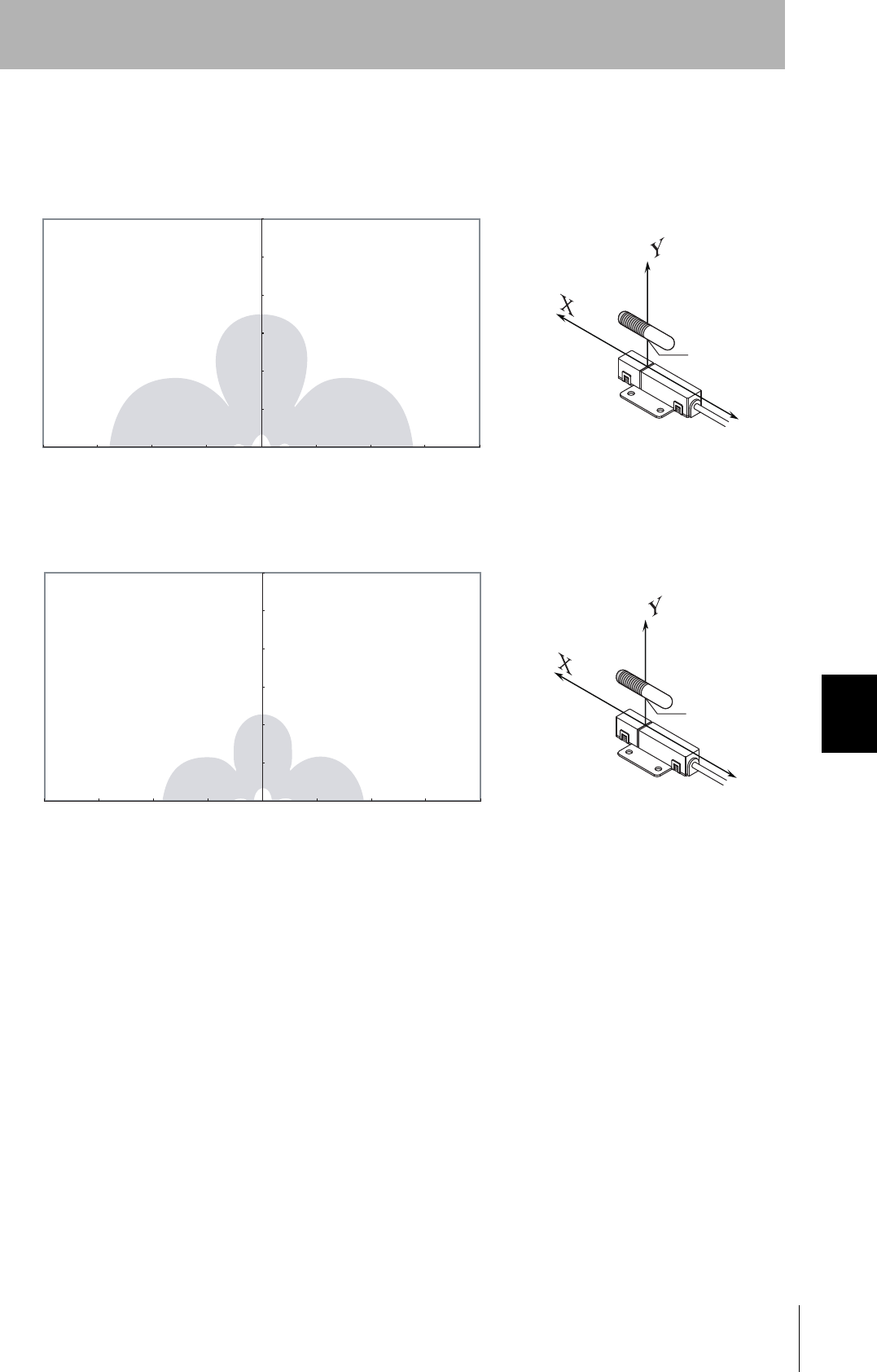
• Parallel Mounting (RI-TRP-DR2B)
• READ
• WRITE
10
20
30
40
50
60
70
80
90
100
-80 -70 -60 -50 -40 -30 -20 -10 0 10 20 30 40 50 60 70 80
0
Communications Area (READ)
Distance in Y direction (mm)
Distance in X direction (mm)
Measurement
point
10
20
30
40
50
60
70
80
90
100
-80 -70 -60 -50 -40 -30 -20 -10 0 10 20 30 40 50 60 70 80
0
Communications Area (WRITE)
Distance in Y direction (mm)
Distance in X direction (mm)
Measurement
point
84
SECTION 7
Characteristic Data According to Conditions of Use
CIDRW System
User’s Manual
SECTION 7
Appendix
• Parallel Mounting (RI-TRP-DR2B)
• READ
• WRITE
010-10 20-20-30 30 40-40-50 50-60-70-80 60 70 80
0
10
20
30
40
50
60
70
80
90
100
Communications Area (READ)
Distance in Y direction (mm)
Distance in Z direction (mm)
Measurement
point
0
10
20
30
40
50
60
70
80
90
100
010-10 20-20-30 30 40-40-50 50-60-70-80 60 70 80
Communications Area (WRITE)
Distance in Y direction (mm)
Distance in Z direction (mm)
Measurement
point
CIDRW System
User’s Manual
SECTION 7
Characteristic Data According to Conditions of Use
SECTION 7
Appendix
85
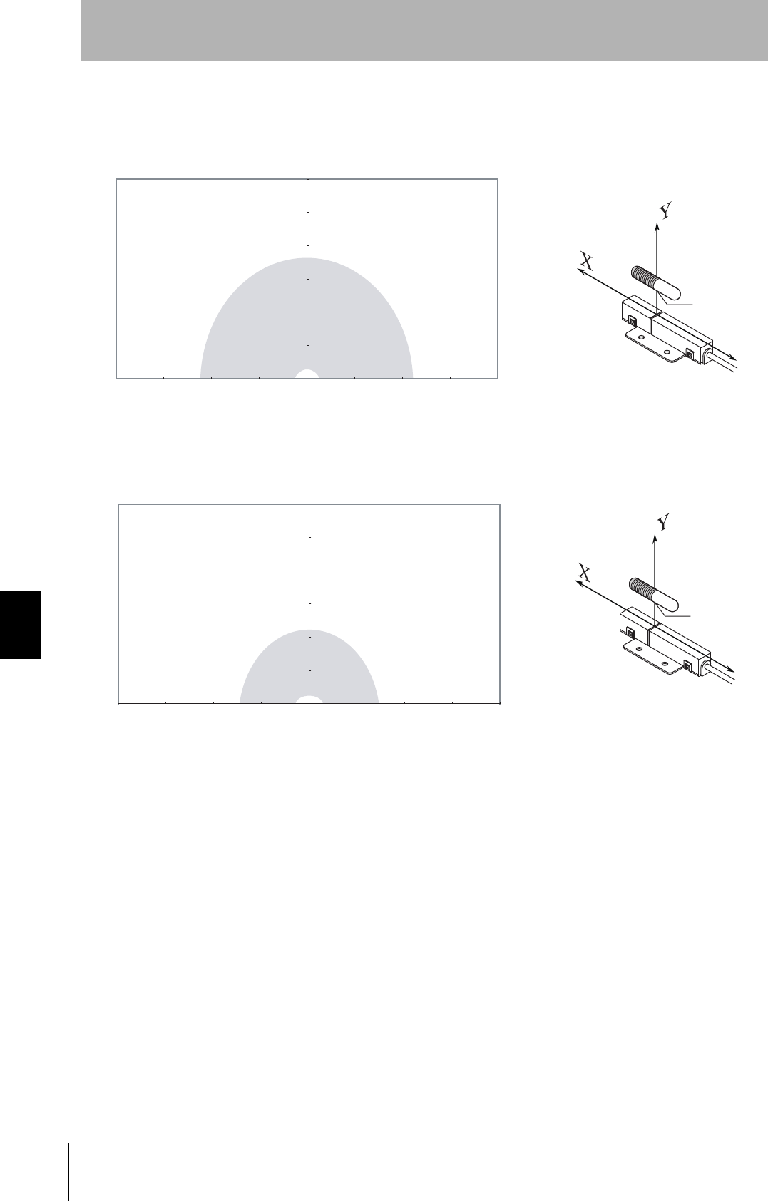
• Vertical Mounting (RI-TRP-DR2B)
• READ
• WRITE
0
10
20
30
40
50
60
70
80
90
100
-80 -70 -60 -50 -40 -30 -20 -10 0 10 20 30 40 50 60 70 80
Communications Area (READ)
Distance in Y direction (mm)
Distance in X direction (mm)
Measurement
point
0
10
20
30
40
50
60
70
80
90
100
-80 -70 -60 -50 -40 -30 -20 -10 0 10 20 30 40 50 60 70 80
Communications Area (WRITE)
Distance in Y direction (mm)
Distance in X direction (mm)
Measurement
point
86
SECTION 7
Characteristic Data According to Conditions of Use
CIDRW System
User’s Manual
SECTION 7
Appendix
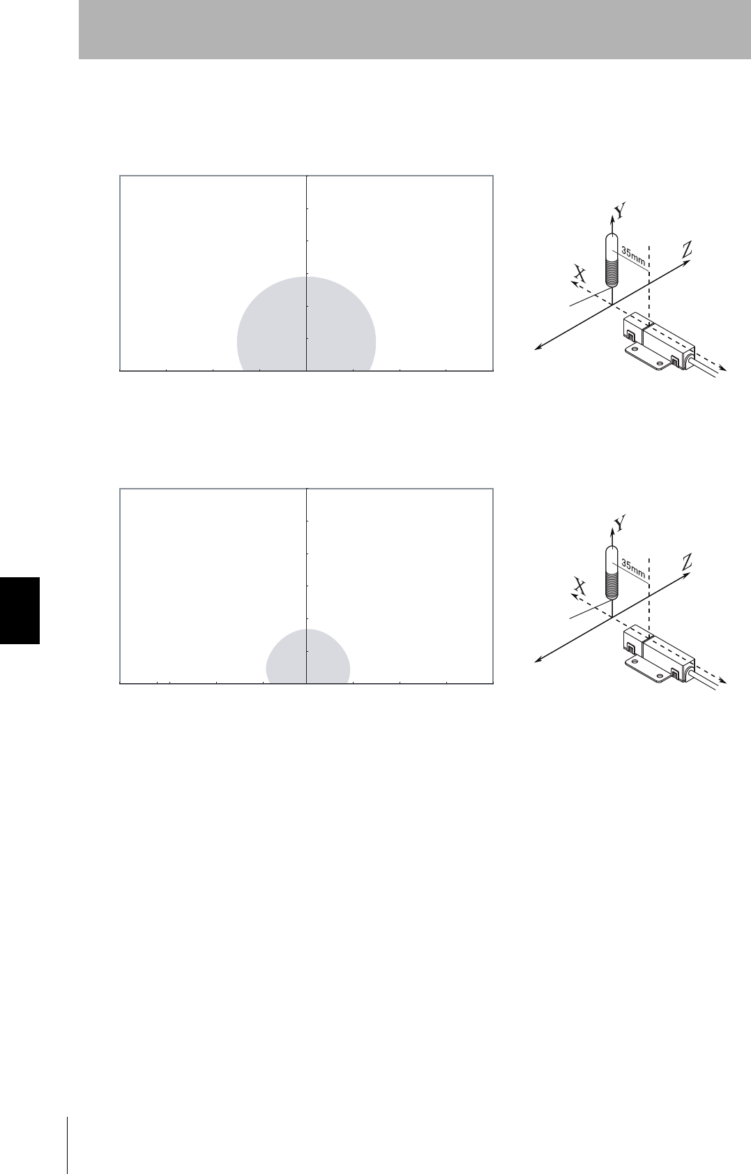
• Vertical Mounting (RI-TRP-DR2B)
• READ
• WRITE
010-10 20-20-30 30 40-40-50 50-60-70-80 60 70 80
0
10
20
30
40
50
60
70
80
90
100
Communications Area (READ)
Distance in Y direction (mm)
Distance in Z direction (mm)
Measurement
point
0
10
20
30
40
50
60
70
80
90
100
010-10 20-20-30 30 40-40-50 50-60-70-80 60 70 80
Communications Area (WRITE)
Distance in Y direction (mm)
Distance in Z direction (mm)
Measurement
point
CIDRW System
User’s Manual
SECTION 7
Characteristic Data According to Conditions of Use
SECTION 7
Appendix
87
• Coaxial Mounting (RI-TRP-WR2B)
• READ
• WRITE
0
30
60
90
120
150
180
-200 0 50 100 150 200-200 -150 -100 -50
Distance in Y direction (mm)
Distance in X direction (mm)
Measurement
point
Communications Area (READ)
0
30
60
90
120
150
180
-200 0 50 100 150 200-150 -100 -50
Distance in Y direction (mm)
Distance in X direction (mm)
Measurement
point
Communications Area (WRITE)
88
SECTION 7
Characteristic Data According to Conditions of Use
CIDRW System
User’s Manual
SECTION 7
Appendix
• Coaxial Mounting (RI-TRP-WR2B)
• READ
• WRITE
0
30
60
90
120
150
180
-200 0 50 100 150 200-150 -100 -50
Distance in Y direction (mm)
Distance in Z direction (mm)
Measurement
point
Communications Area (READ)
0
30
60
90
120
150
180
-200 0 50 100 150 200-150 -100 -50
Distance in Y direction (mm)
Distance in Z direction (mm)
Measurement
point
Communications Area (WRITE)
CIDRW System
User’s Manual
SECTION 7
Characteristic Data According to Conditions of Use
SECTION 7
Appendix
89
• Parallel Mounting (RI-TRP-WR2B)
• READ
• WRITE
0
30
60
90
120
150
180
-200 0 50 100 150 200-150 -100 -50
Distance in Y direction (mm)
Distance in X direction (mm)
Measurement
point
Communications Area (READ)
0
30
60
90
120
150
180
-200 0 20050 100 150-150 -100 -50
Distance in Y direction (mm)
Distance in X direction (mm)
Measurement
point
Communications Area (WRITE)
90
SECTION 7
Characteristic Data According to Conditions of Use
CIDRW System
User’s Manual
SECTION 7
Appendix
• Parallel Mounting (RI-TRP-WR2B)
• READ
• WRITE
0
30
60
90
120
150
180
-200 -150 -100 -50 0 50 100 150 200
Distance in Y direction (mm)
Distance in Z direction (mm)
Measurement
point
Communications Area (READ)
0
30
60
90
120
150
180
0 50 100 150 200-200 -150 -100 -50
Distance in Y direction (mm)
Distance in Z direction (mm)
Measurement
point
Communications Area (WRITE)

CIDRW System
User’s Manual
SECTION 7
Characteristic Data According to Conditions of Use
SECTION 7
Appendix
91
• Vertical Mounting (RI-TRP-WR2B)
• READ
• WRITE
0
30
60
90
120
150
180
-200 0 20050 100 150-150 -100 -50
Distance in Y direction (mm)
Distance in X direction (mm)
Measurement
point
Communications Area (READ)
0
30
60
90
120
150
180
-200 0 20050 100 150-150 -100 -50
Distance in Y direction (mm)
Distance in X direction (mm)
Measurement
point
Communications Area (WRITE)
92
SECTION 7
Characteristic Data According to Conditions of Use
CIDRW System
User’s Manual
SECTION 7
Appendix
• Vertical Mounting (RI-TRP-WR2B)
• READ
• WRITE
0
30
60
90
120
150
180
-200 0 20050 100 150-150 -100 -50
Distance in Y direction (mm)
Distance in Z direction (mm)
Measurement
point
Communications Area (READ)
0
30
60
90
120
150
180
-200 -150 -100 -50 50 100 150 2000
Distance in Y direction (mm)
Distance in Z direction (mm)
Measurement
point
Communications Area (READ)
CIDRW System
User’s Manual
SECTION 7
Characteristic Data According to Conditions of Use
SECTION 7
Appendix
93
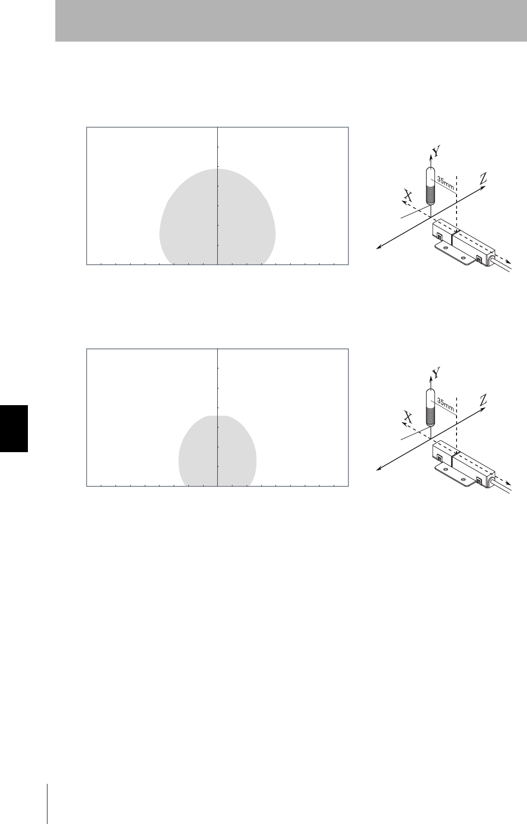
■V640-HAM11-L-ETN
• Coaxial Mounting (RI-TRP-DR2B)
• READ
• WRITE
Communications Area (READ)
Distance in Y direction (mm)
Distance in X direction (mm)
Measurement point
0-20
0
20
40
60
80
100
120
140
-40-60-80-100-120-140-160-180 18016014012010080604020
Communications Area (READ)
Distance in Y direction (mm)
Distance in X direction (mm)
Measurement point
0-20
0
20
40
60
80
100
120
140
-40-60-80-100-120-140-160-180 18016014012010080604020
94
SECTION 7
Characteristic Data According to Conditions of Use
CIDRW System
User’s Manual
SECTION 7
Appendix
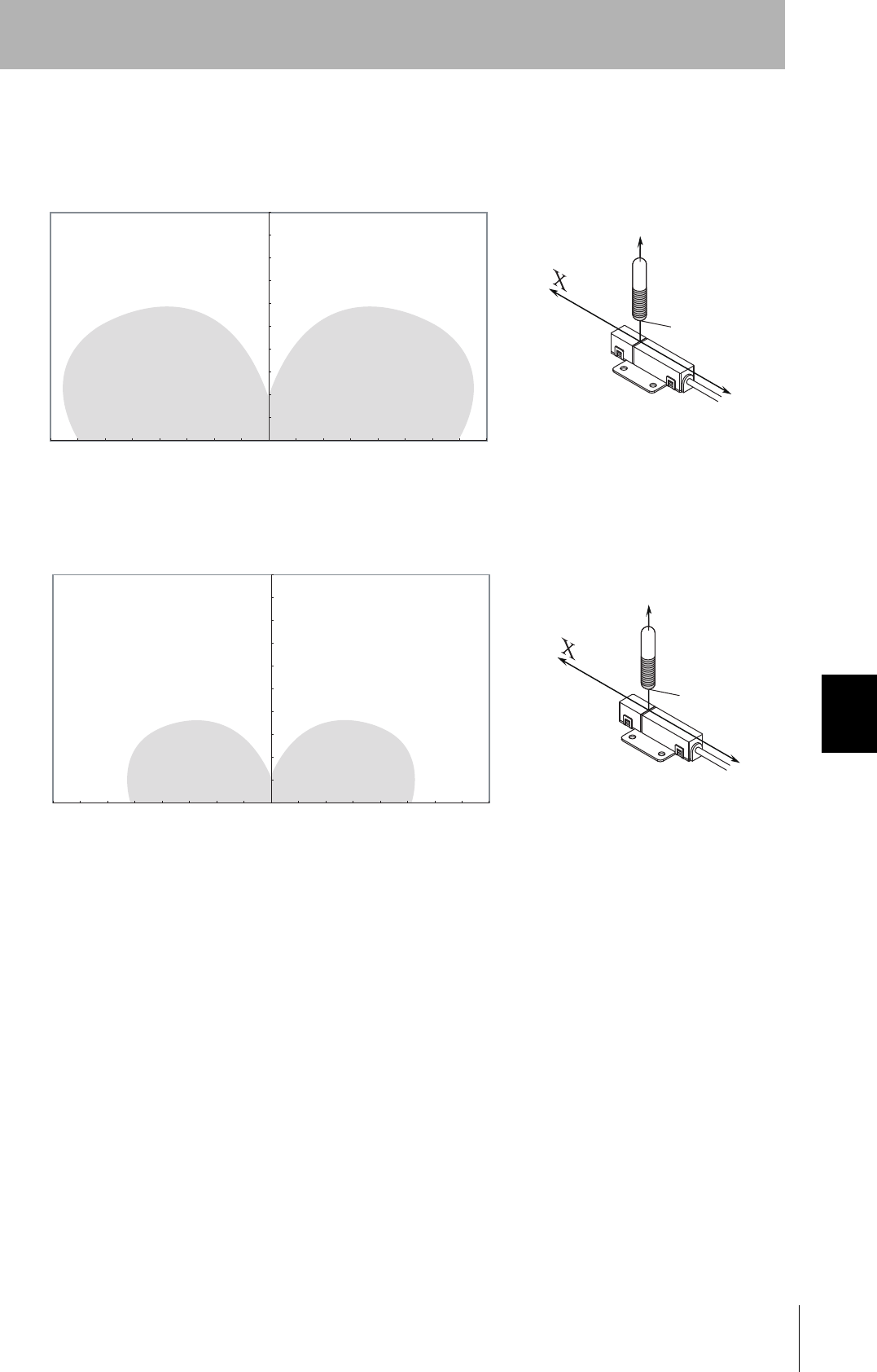
• Coaxial Mounting (RI-TRP-DR2B)
• READ
• WRITE
Communications Area (READ)
Distance in Z direction (mm)
Measurement point
Distance in Y direction (mm)
0-20
0
20
40
60
80
100
120
140
-40-60-80-100-120-140-160-180 18016014012010080604020
Communications Area (READ)
Distance in Z direction (mm)
Measurement point
Distance in Y direction (mm)
0-20
0
20
40
60
80
100
120
140
-40-60-80-100-120-140-160-180 18016014012010080604020
CIDRW System
User’s Manual
SECTION 7
Characteristic Data According to Conditions of Use
SECTION 7
Appendix
95
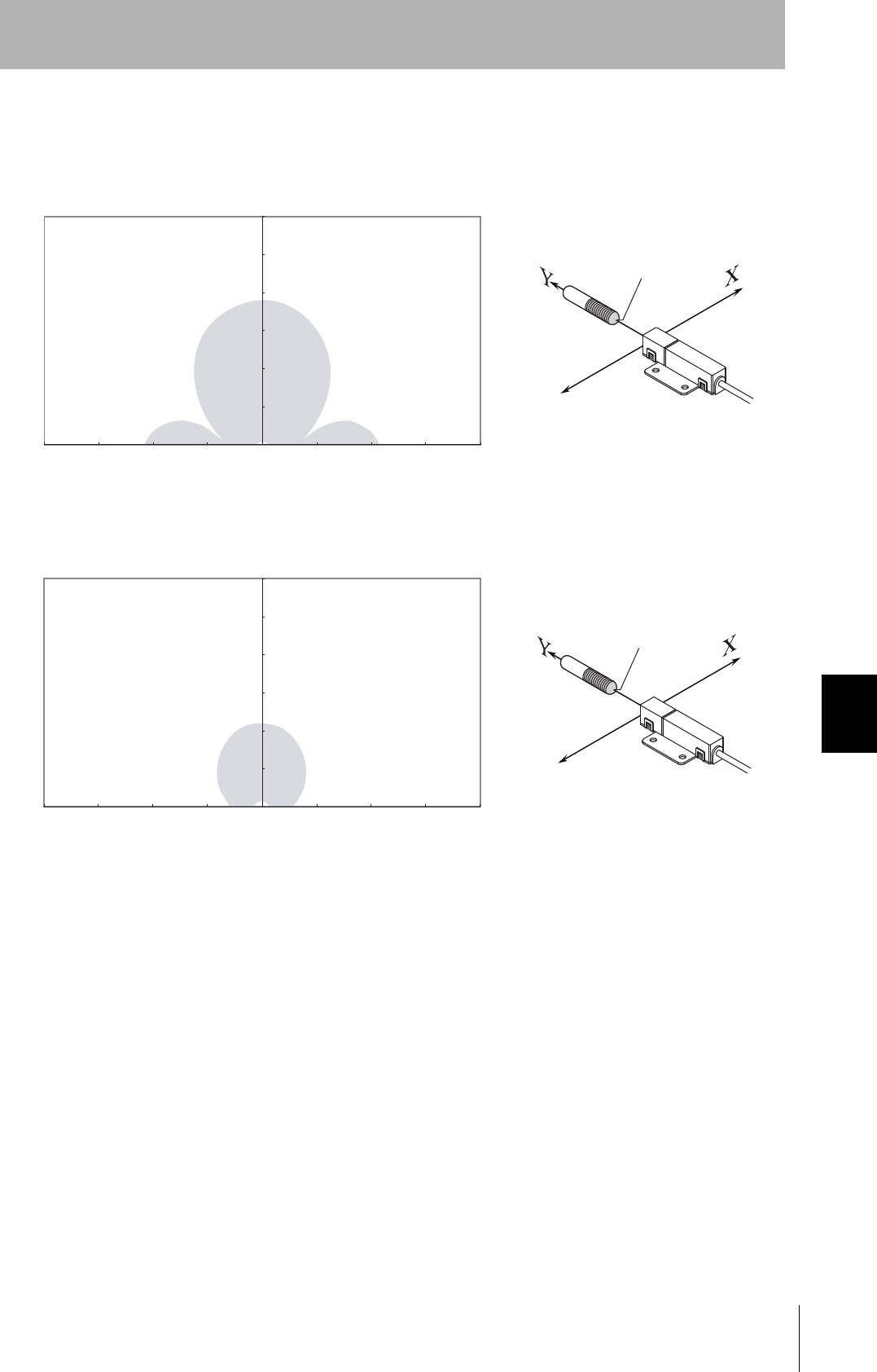
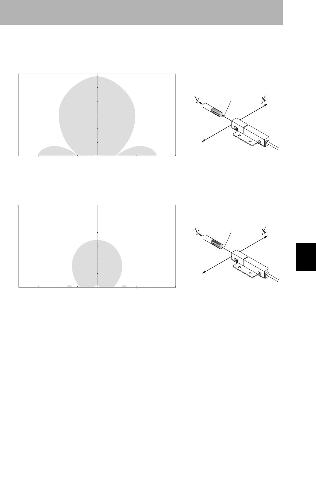
• Parallel Mounting (RI-TRP-DR2B)
• READ
• WRITE
Communications Area (READ)
Distance in Y direction (mm)
Distance in X direction (mm)
Measurement
point
0-20
0
20
40
60
80
100
120
140
-40-60-80-100-120-140-160-180 18016014012010080604020
Communications Area (READ)
Distance in Y direction (mm)
Distance in X direction (mm)
Measurement
point
0-20
0
20
40
60
80
100
120
140
-40-60-80-100-120-140-160-180 18016014012010080604020

96
SECTION 7
Characteristic Data According to Conditions of Use
CIDRW System
User’s Manual
SECTION 7
Appendix
• Parallel Mounting (RI-TRP-DR2B)
• READ
• WRITE
Communications Area (READ)
Distance in Y direction (mm)
Distance in Z direction (mm)
Measurement
point
0-20
0
20
40
60
80
100
120
140
-40-60-80-100-120-140-160-180 18016014012010080604020
Communications Area (READ)
Distance in Y direction (mm)
Distance in Z direction (mm)
Measurement
point
0-20
0
20
40
60
80
100
120
140
-40-60-80-100-120-140-160-180 18016014012010080604020
CIDRW System
User’s Manual
SECTION 7
Characteristic Data According to Conditions of Use
SECTION 7
Appendix
97
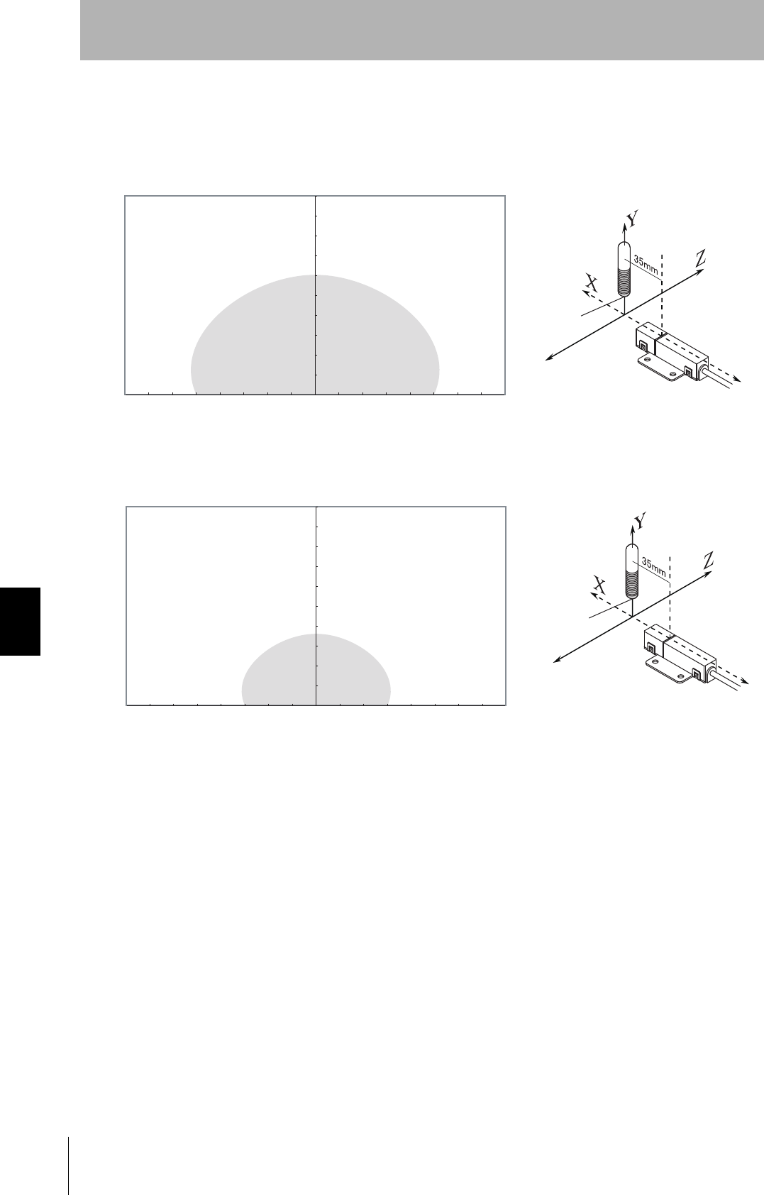
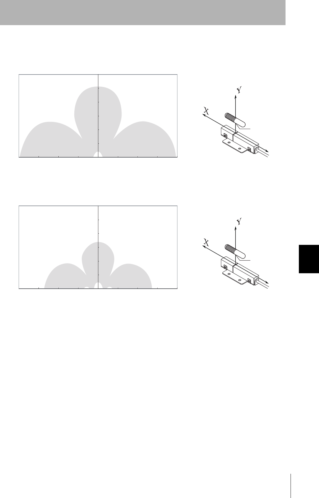
• Vertical Mounting (RI-TRP-DR2B)
• READ
• WRITE
Communications Area (READ)
Distance in Y direction (mm)
Distance in X direction (mm)
Measurement
point
0-20
0
20
40
60
80
100
120
140
-40-60-80-100-120-140-160-180 18016014012010080604020
Communications Area (READ)
Distance in Y direction (mm)
Distance in X direction (mm)
Measurement
point
0-20
0
20
40
60
80
100
120
140
-40-60-80-100-120-140-160-180 18016014012010080604020
98
SECTION 7
Characteristic Data According to Conditions of Use
CIDRW System
User’s Manual
SECTION 7
Appendix
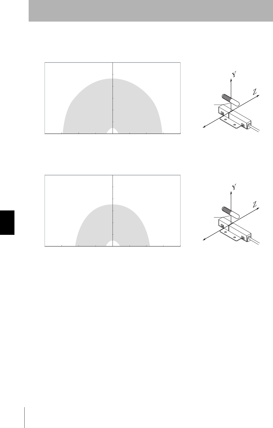
• Vertical Mounting (RI-TRP-DR2B)
• READ
• WRITE
Communications Area (READ)
Distance in Y direction (mm)
Distance in Z direction (mm)
Measurement
point
0-20
0
20
40
60
80
100
120
140
-40-60-80-100-120-140-160-180 18016014012010080604020
Communications Area (READ)
Distance in Y direction (mm)
Distance in Z direction (mm)
Measurement
point
0-20
0
20
40
60
80
100
120
140
-40-60-80-100-120-140-160-180 18016014012010080604020
CIDRW System
User’s Manual
SECTION 7
Characteristic Data According to Conditions of Use
SECTION 7
Appendix
99
• Coaxial Mounting (RI-TRP-WR2B)
• READ
• WRITE
Distance in Y direction (mm)
Distance in X direction (mm)
Measurement
point
Communications Area (READ)
0
0
-50
30
50
60
90
120
150
180
-100 100-150 150-200 200
Distance in Y direction (mm)
Distance in X direction (mm)
Measurement
point
Communications Area (READ)
㪇
㪇
㪄㪌㪇
㪊㪇
㪌㪇
㪍㪇
㪐㪇
㪈㪉㪇
㪈㪌㪇
㪈㪏㪇
㪄㪈㪇㪇 㪈㪇㪇㪄㪈㪌㪇 㪈㪌㪇㪄㪉㪇㪇 㪉㪇㪇

100
SECTION 7
Characteristic Data According to Conditions of Use
CIDRW System
User’s Manual
SECTION 7
Appendix
• Coaxial Mounting (RI-TRP-WR2B)
• READ
• WRITE
Distance in Y direction (mm)
Distance in Z direction (mm)
Measurement
point
Communications Area (READ)
0
0
-50
30
50
60
90
120
150
180
-100 100-150 150-200 200
Distance in Y direction (mm)
Distance in Z direction (mm)
Measurement
point
Communications Area (READ)
0
0
-50
30
50
60
90
120
150
180
-100 100-150 150-200 200
CIDRW System
User’s Manual
SECTION 7
Characteristic Data According to Conditions of Use
SECTION 7
Appendix
101
• Parallel Mounting (RI-TRP-WR2B)
• READ
• WRITE
Distance in Y direction (mm)
Distance in X direction (mm)
Measurement
point
Communications Area (READ)
0
0
-50
30
50
60
90
120
150
180
-100 100-150 150-200 200
Distance in Y direction (mm)
Distance in X direction (mm)
Measurement
point
Communications Area (READ)
0
0
-50
30
50
60
90
120
150
180
-100 100-150 150-200 200
102
SECTION 7
Characteristic Data According to Conditions of Use
CIDRW System
User’s Manual
SECTION 7
Appendix
• Parallel Mounting (RI-TRP-WR2B)
• READ
• WRITE
Distance in Y direction (mm)
Distance in Z direction (mm)
Measurement
point
Communications Area (READ)
0
0
-50
30
50
60
90
120
150
180
-100 100-150 150-200 200
Distance in Y direction (mm)
Distance in Z direction (mm)
Measurement
point
Communications Area (READ)
0
0
-50
30
50
60
90
120
150
180
-100 100-150 150-200 200
CIDRW System
User’s Manual
SECTION 7
Characteristic Data According to Conditions of Use
SECTION 7
Appendix
103
• Vertical Mounting (RI-TRP-WR2B)
• READ
• WRITE
Distance in Y direction (mm)
Distance in X direction (mm)
Measurement
point
Communications Area (READ)
0
0
-50
30
50
60
90
120
150
180
-100 100-150 150-200 200
Distance in Y direction (mm)
Distance in X direction (mm)
Measurement
point
Communications Area (READ)
0
0
-50
30
50
60
90
120
150
180
-100 100-150 150-200 200
104
SECTION 7
Characteristic Data According to Conditions of Use
CIDRW System
User’s Manual
SECTION 7
Appendix
• Vertical Mounting (RI-TRP-WR2B)
• READ
• WRITE
Distance in Y direction (mm)
Distance in Z direction (mm)
Measurement
point
Communications Area (READ)
0
0
-50
30
50
60
90
120
150
180
-100 100-150 150-200 200
Distance in Y direction (mm)
Distance in Z direction (mm)
Measurement
point
Communications Area (READ)
0
0
-50
30
50
60
90
120
150
180
-100 100-150 150-200 200
CIDRW System
User’s Manual
SECTION 7
Characteristic Data According to Conditions of Use
SECTION 7
Appendix
105
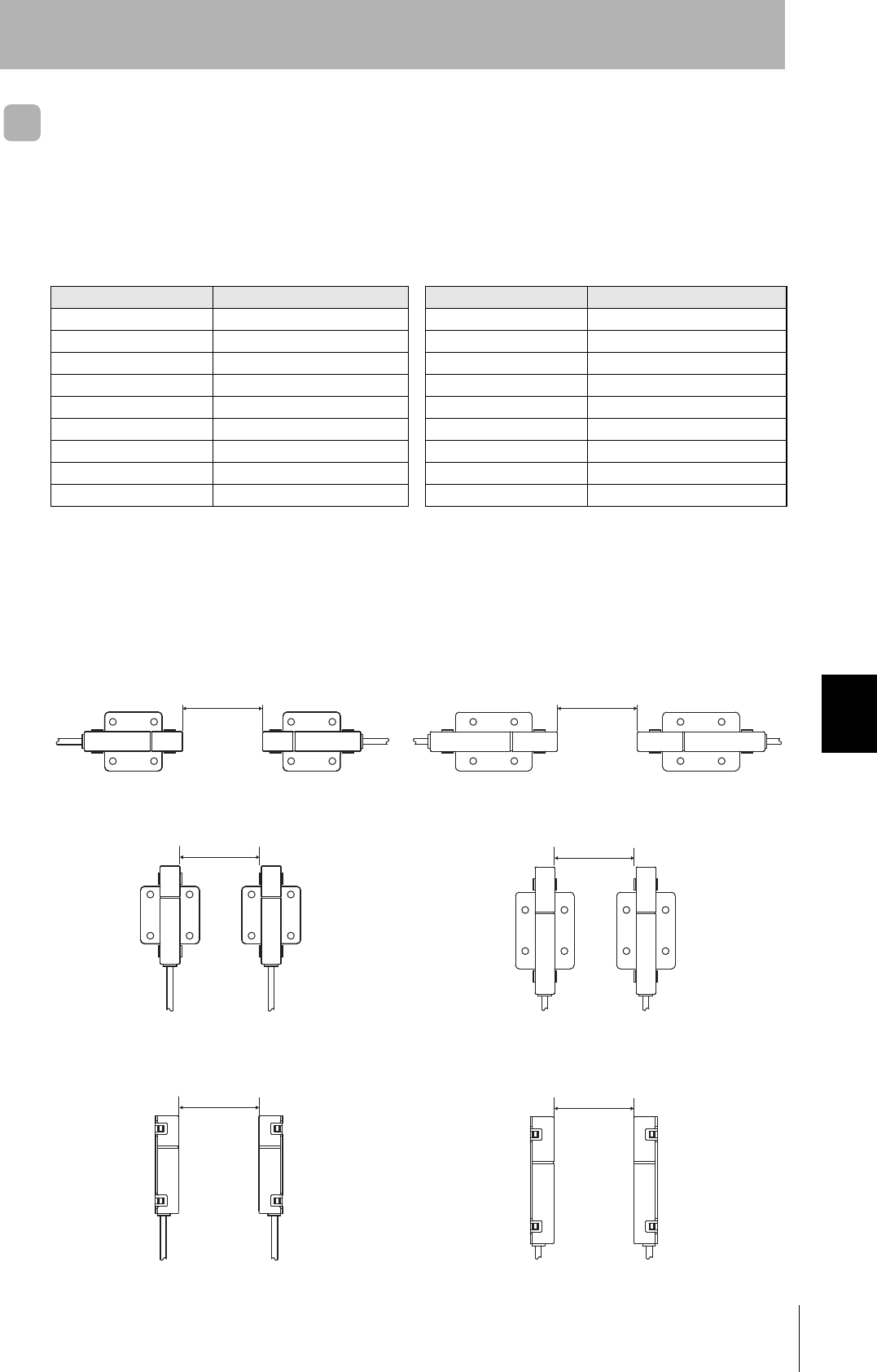
Mutual Interference Distances (Reference Only)
If Amplifier Units are connected using multidrop connections and multiple CIDRW Heads are used, the
CIDRW Heads will not process commands simultaneously. In this case, install the CIDRW Heads at
least 0.1 m apart from each other.
Distance between Antennas and Changes in Communications Distances (Reference Only)
If CIDRW Heads in separate CIDRW systems process commands simultaneously when the CIDRW
Systems are installed close to each other, mutual interference between the Heads can result in mal-
functions. If this is a problem, install the CIDRW Heads separated at least by the distances shown in
the following illustrations.
■For Coaxial Installation
■For Parallel Installation
■For Face-to-Face Installation
• V640-HS61 • V640-HS62
Distance between Antennas Change in communications distance Distance between Antennas Change in communications distance
1,000 mm 100% 2,000 mm 99%
900 mm 100% 1,600 mm 99%
800 mm 100% 1,400 mm 95%
700 mm 99% 1,200 mm 84%
600 mm 90% 1,000 mm 68%
500 mm 74% 800 mm 53%
400 mm 55% 600 mm 34%
300 mm 40% 400 mm 15%
200 mm 15% 200 mm 0%
1 m min.
• V640-HS61 • V640-HS62 2 m min.
1 m min.
• V640-HS61 • V640-HS62 2 m min.
1 m min.
• V640-HS61 • V640-HS62 2 m min.
106
SECTION 7
Characteristic Data According to Conditions of Use
CIDRW System
User’s Manual
SECTION 7
Appendix
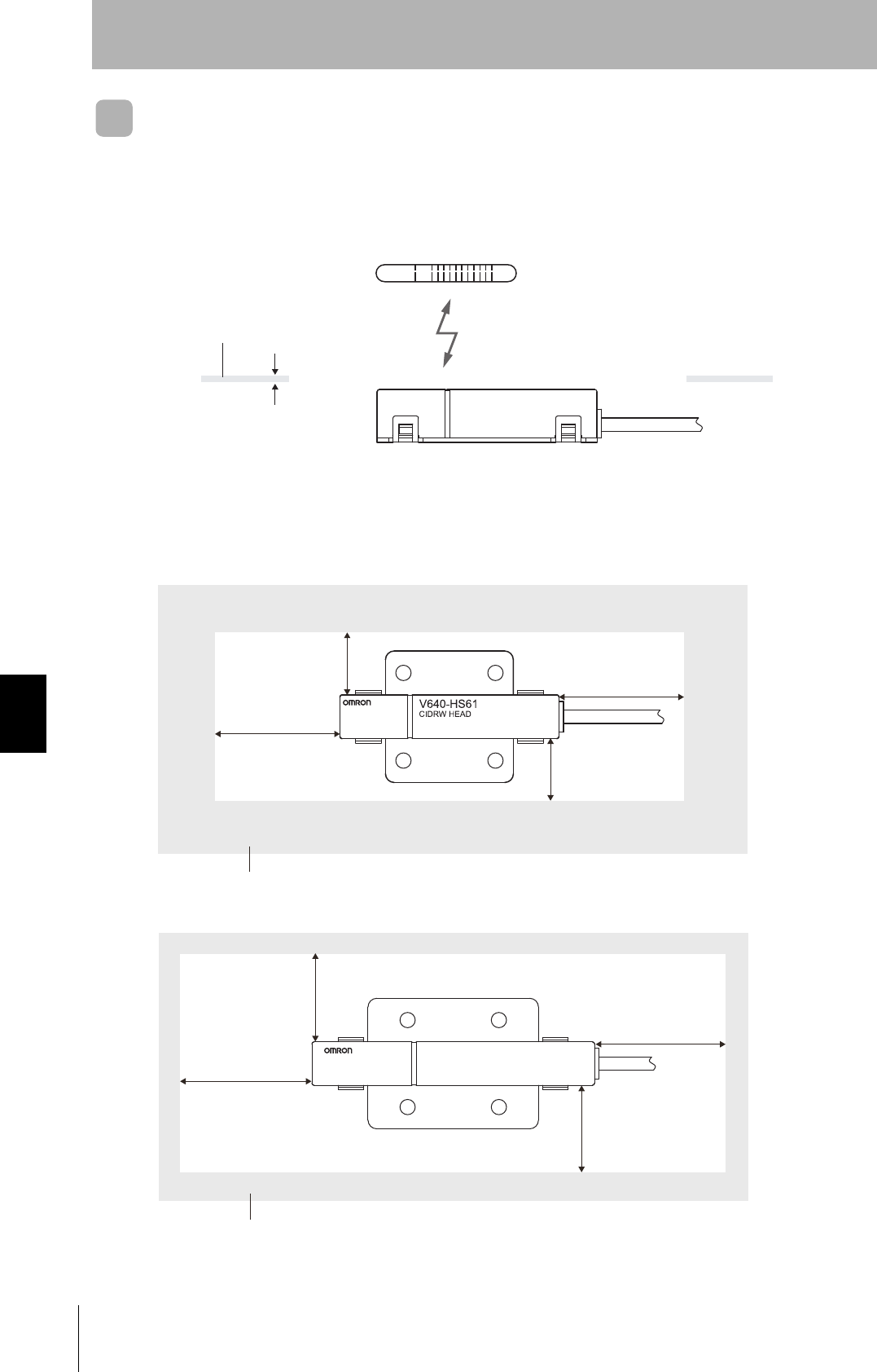
Influence of Background Metals (Reference Only)
The CIDRW Head can also communicate from an opening in a ceiling panel (metal body).
However, ensure the distances indicated below between the CIDRW Head and the metal body. If you
do not ensure these distances the communications distance will be substantially shortened.
Metal body (material: AL, SUS)
(Thickness: 1 mm)
V640-HS62
CIDRW HEAD
MADE IN JAPAN
10 mm min.
10 mm min.
20 mm min.
20 mm min.
Metal body (material: AL, SUS)
• V640-HS61
• V640-HS62
20 mm min.
20 mm min.
30 mm min.
30 mm min.
Metal body (material: AL, SUS)
CIDRW System
User’s Manual
SECTION 7
Characteristic Data According to Conditions of Use
SECTION 7
Appendix
107
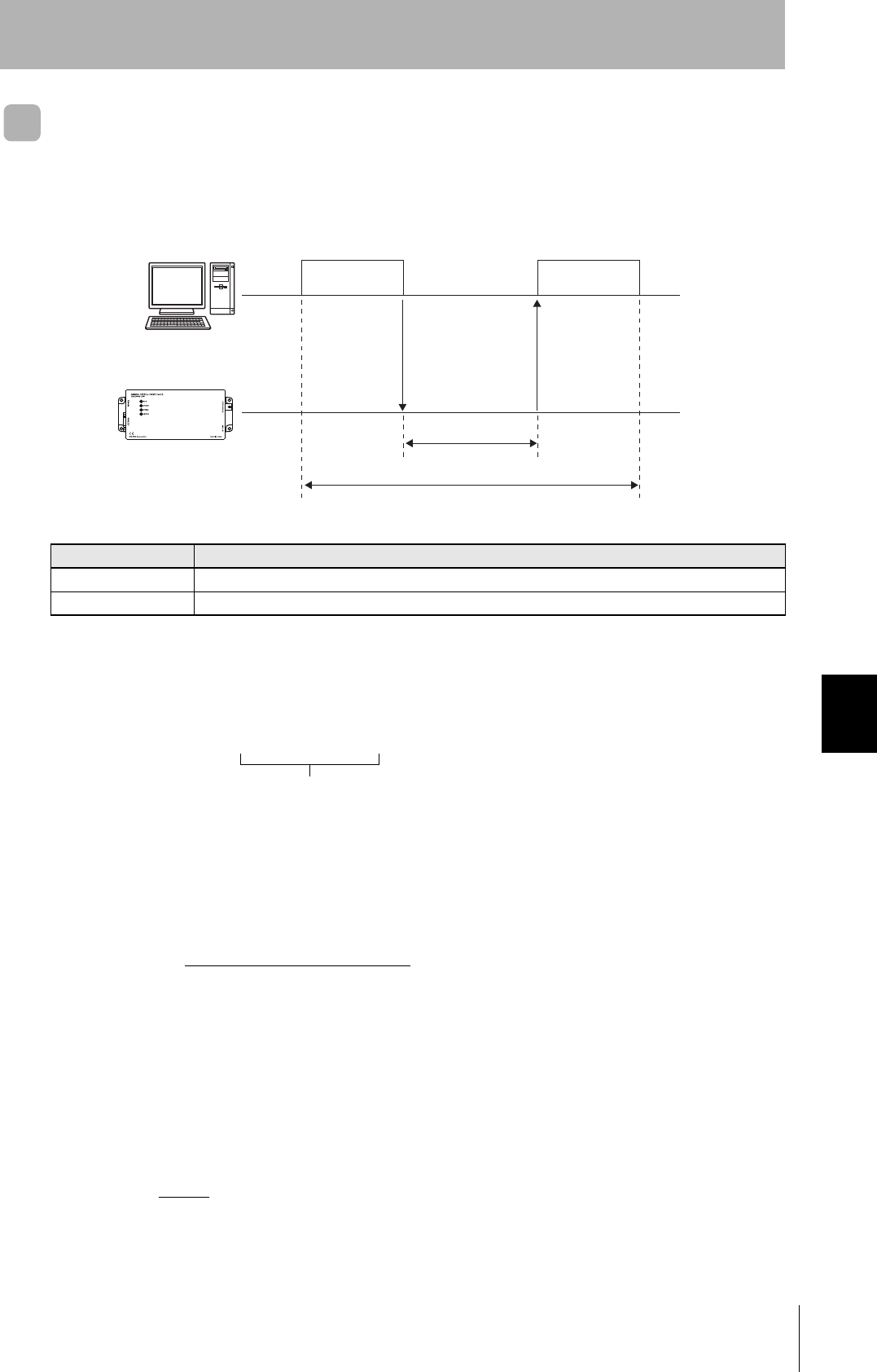
Communications Time
Regardless of whether SECS is used or not, take the time required for processing between the host
device and Amplifier Units into account when designing the system.
Communications time calculation formula (unit: ms)
READ: 150.5 × (number of pages) + 6.1
SAME WRITE: 468.6 × (number of pages) + 80.3
BYTE WRITE: 468.6 × (number of pages/8) + 229.9
TAT calculation formula (units: ms)
TAT = command and response transmission time + communications time
The command and response transmission time differs depending on the number of characters
sent and the communications conditions.
This calculation applies to continuous transmission in which the Controller uses no spaces
between command characters.
Example of TAT calculation:
Number of command characters: A; number of response characters: B
Baud rate: 9600 bps, data length: 8 bits, non parity, 1 stop bit
Time Description
Communications time This is the time required for communications between an ID Tag and the CIDRW Head.
TAT This is the time required for processing at the Amplifier Unit, seen from the host device.
Host
Amplifier Unit
Command Response
Communications time
TAT
Rounding up
Transmission time (ms) = Number of bits per character (bits)
Baud rate (bps)
× total number of characters of command and response
TAT (ms) = 10
9600
× (A + B) + Communications time (ms)
108
SECTION 7
Characteristic Data According to Conditions of Use
CIDRW System
User’s Manual
SECTION 7
Appendix
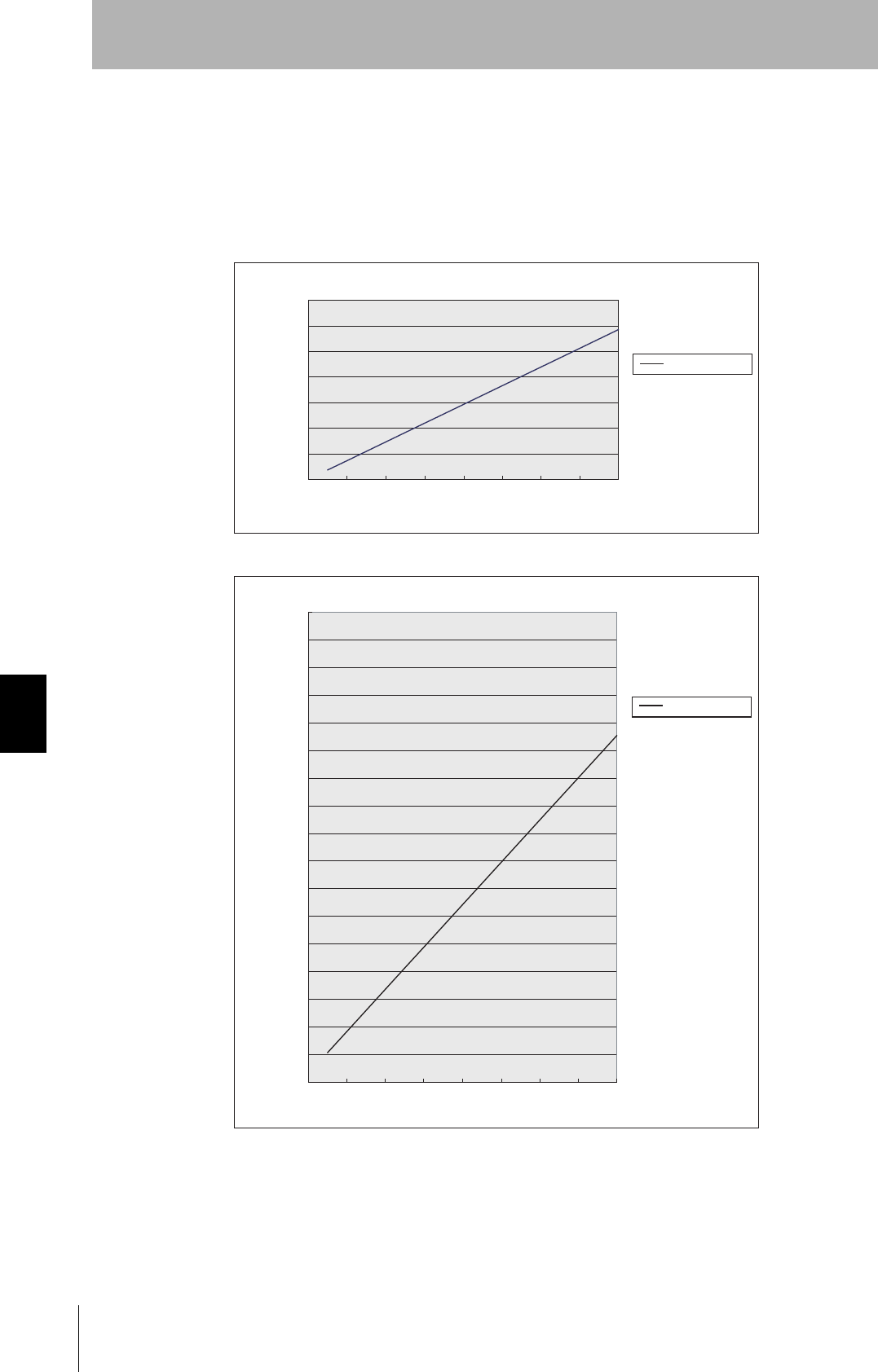
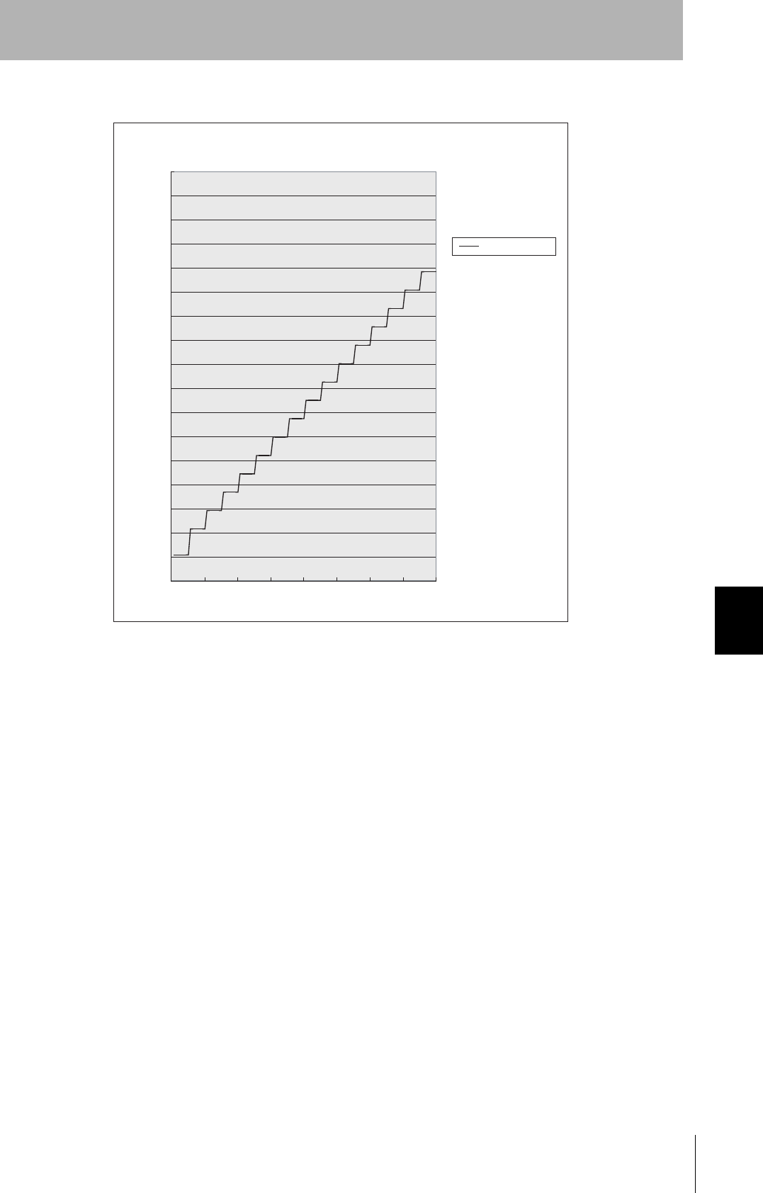
The graph for communications time for communications between the ID Tag and CIDRW Head, and
TAT (when the baud rate is 9600 bps), is shown below.
The communications time and TAT, however, may increase substantially according to the conditions of
use.
0
500
1000
1500
2000
2500
3000
3500
Read
Number of pages processed
Communications time
Communications time (ms)
0
500
1000
1500
2000
2500
3000
3500
4000
4500
5000
5500
6000
6500
7000
7500
8000
8500
1246810121416
Communications time (ms)
Write (SAME WRITE)
Number of pages processed
Communications time
CIDRW System
User’s Manual
SECTION 7
Characteristic Data According to Conditions of Use
SECTION 7
Appendix
109
0
500
1000
1500
2000
2500
3000
3500
4000
4500
5000
5500
6000
6500
7000
7500
8000
8500
1 16 32 48 64 80 96 112 128
Communications time (ms)
BYTE WRITE
Number of bytes processed
Communications time
110
SECTION 7
Characteristic Data According to Conditions of Use
CIDRW System
User’s Manual
SECTION 7
Appendix
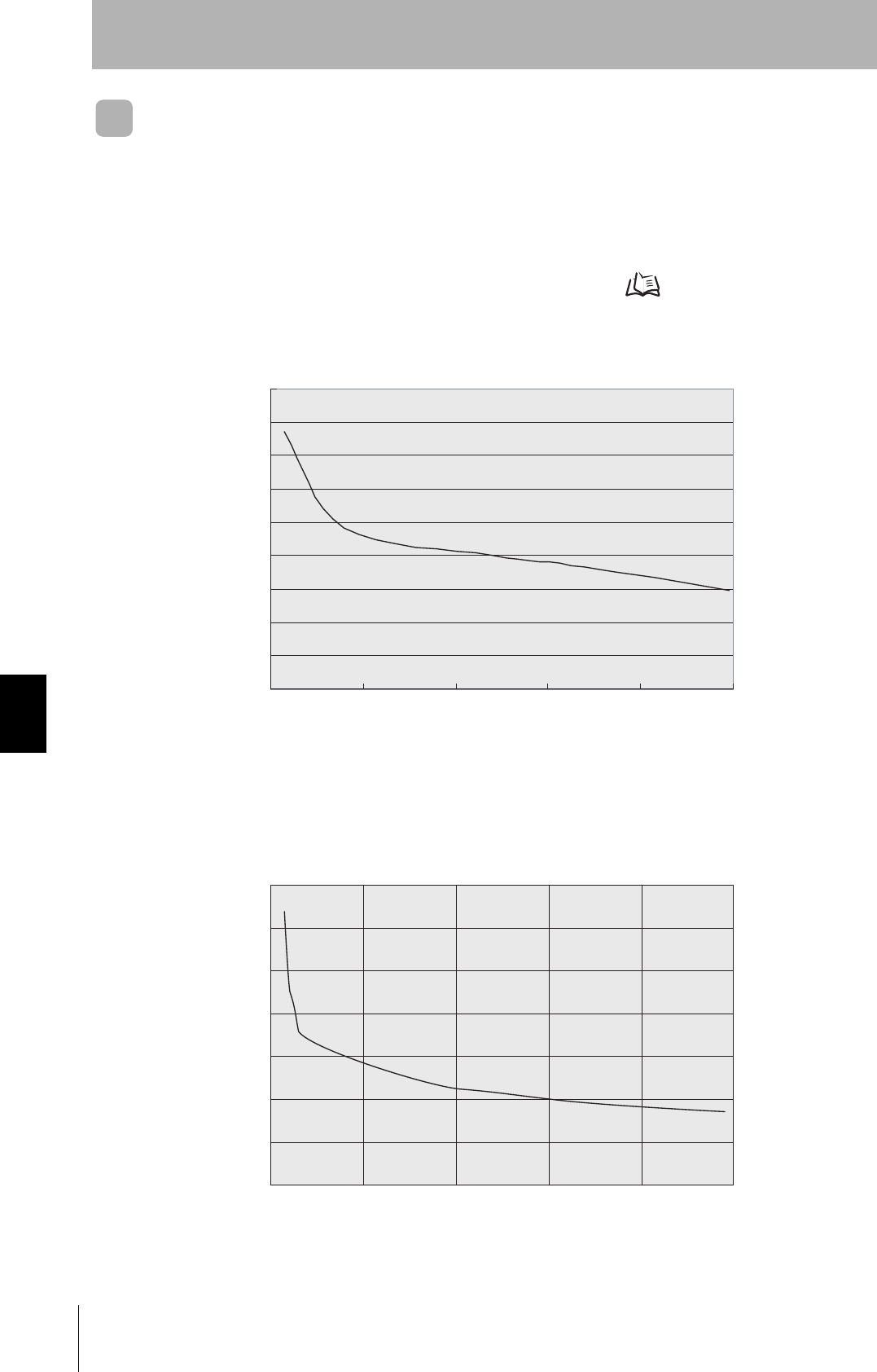
Communications Distance Characteristics vs. Ambient Noise
The graph below compares the results of measurement using the noise measurement function with
communications distances.
At installation implement measures in regard to metal in the vicinity of the CIDRW Head, power supply
noise, and atmospheric noise, to ensure that the noise level does not exceed 10.
NOISE MEASUREMENT command (applies only when SECS is not used) Refer to page 49.
■V640-HAM11-ETN
■V640-HAM11-L-ETN
0
10
20
30
40
50
60
70
80
90
02040608099
(MAX)
Noise level
Communications distance (mm)
Relationship between noise level and communications distance (reference values)
(Max.)
0
20
40
60
80
100
120
140
0 20 40 60 80 100
(MAX)
Noise level
Communications distance (mm)
Relationship between noise level and communications distance (reference values)
(Max.)
CIDRW System
User’s Manual
SECTION 7
ID Tag Memory Maps
SECTION 7
Appendix
111
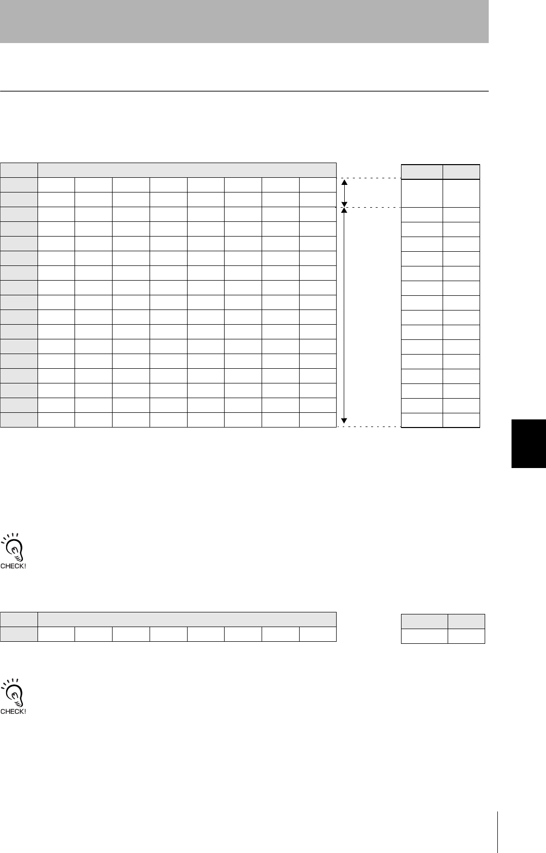
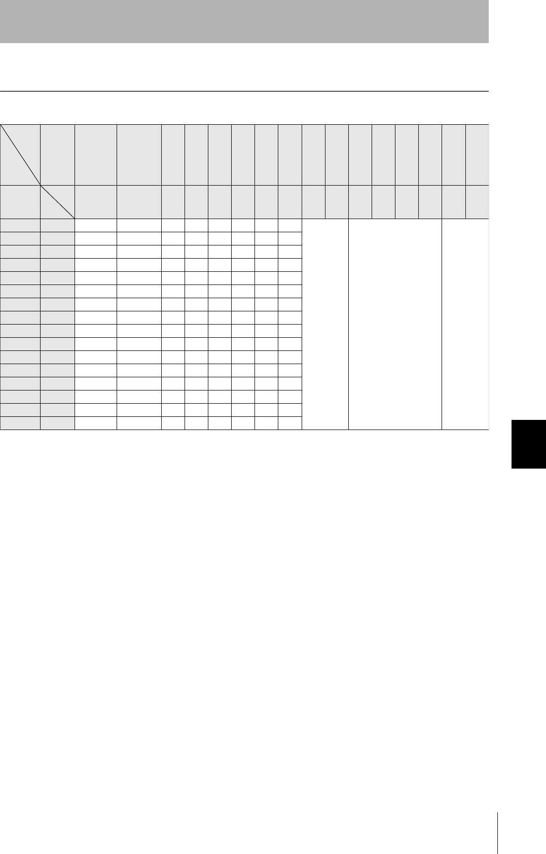
ID Tag Memory Maps
The memory maps of the RI-TRP-DR2B and RI-TRP-WR2B ID Tags are given below.
• The carrier ID memory area starts from page 1 (fixed).
• 00h to 87h in the table are addresses.
• The RI-TRP-WR2B has a memory capacity of 136 bytes.
• The RI-TRP-WR2B has a memory capacity of 8 bytes.
Page 8 bytes/1 page
1 00h 01h 02h 03h 04h 05h 06h 07h
2 08h 09h 0Ah 0Bh 0Ch 0Dh 0Eh 0Fh
3 10h 11h 12h 13h 14h 15h 16h 17h
4 18h 19h 1Ah 1Bh 1Ch 1Dh 1Eh 1Fh
5 20h 21h ••• ••• 27h
6 28h 29h ••• ••• 2Fh
7 30h 31h ••• ••• 37h
8
9 :
10 : :
11 :
12
13
14 68h 69h ••• ••• 6Fh
15 70h 71h ••• ••• 77h
16 78h 79h ••• ••• 7Fh
17 80h 81h ••• ••• 87h
DATASEG LENGTH
Carrier
ID
16
"S01" 8
"S02" 8
"S03" 8
"S04" 8
"S05" 8
"S06" 8
"S07" 8
"S08" 8
"S09" 8
"S10" 8
"S11" 8
"S12" 8
"S13" 8
"S14" 8
"S15" 8
Carrier ID
(16 byte)
Data area
(Total of 120
bytes)
■RI-TRP-DR2B
ID Tag Memory Map Example of data
segment settings
Page 8 bytes/1 page
1 00h 01h 02h 03h 04h 05h 06h 07h
DATASEG LENGTH
Carrier ID 8
Carrier ID
(8 byte)
■RI-TRP-WR2B
ID Tag Memory Map Example of data
segment settings

112
SECTION 7
Regular Inspection
CIDRW System
User’s Manual
SECTION 7
Appendix
Regular Inspection
In order to maintain optimum performance of the functions of the CIDRW system, daily and periodic
inspections are necessary.
Inspection item Detail Criteria Tools required
Supply voltage fluctuation Check that the supply voltage fluctuation
at the power supply terminal block is
within the permissible range.
To be within supply voltage rating. Multimeter
Check that there are no frequent instan-
taneous power failures or radical voltage
drops.
To be within permissible voltage fluctua-
tion range.
Power supply
analyzer
Environment Ambient tem-
perature
Check that the ambient temperature and
humidity are within specified range.
To be within the specified range. Maximum and
minimum ther-
mometer
Hygrometer
Ambient
humidity
Vibration and
shock
Check that no vibration or shock is trans-
mitted from any machines.
Dust Check that the system is free of dust
accumulation.
To be none.
Corrosive gas Check that no metal part of the system is
discolored or corroded.
I/O power
supply
Voltage fluctu-
ation
Check on the I/O terminal block that the
voltage fluctuation and ripple are within
the permissible ranges.
To be within the specified range. Multimeter
Oscilloscope
Ripple
Mounting condition Check that each device is securely
mounted.
There must be no loose screws. —
Check that each connector is securely
connected.
Each connector must be locked or
securely tightened with screws.
Check that no wire is broken or nearly
broken.
There must be no wire that is broken or
nearly broken.
Check if grounding to 100 Ω or less has
been done.
To be grounded to 100 Ω or less.
CIDRW System
User’s Manual
SECTION 7
ASCII Code Table
SECTION 7
Appendix
113
ASCII Code Table
Leftmost
bits
Right-
most bits
b8 to b5
0000 1001 0010 0011 0100 0101 0110 0111 1000 1101 1010 1011 1100 1101 1110 1111
b4 to b1
Row
Line
0 1
2345678910 11 12 13 14 15
0000 0
NUL TC7(DLE)
(SP) 0 @ P ` p
Undefined Undefined Undefined
0001 1
TC1(SOH) DC
1
!1AQaq
0010 2
TC2(STX) DC
2
"2BRbr
0011 3
TC3(ETX) DC
3
#3CScs
0100 4
TC4(EOT) DC
4
$4DTd t
0101 5
TC5(NEQ) TC
8
(NAK)
%5EUe u
0110 6
TC6(ACK) TC
9
(SYN)
&6FV f v
0111 7
BEL TC
10
(ETB)
'7GWgw
1000 5
FE0(BS) CAN
(8HXhx
1001 9
FE1(HT) EM
)9IYiy
1010 10
FE2(LF) SUB
*:JZjz
1011 11
FE3(VT) ESC
+;K[k{
1100 12
FE4(FF) IS
4
(FS)
,<L\ l |
1101 13
FE5(CR) IS
3
(GS)
-=M]m}
1110 14
S0 IS
2
(RS)
.>N^nÅP
1111 15
S1 IS
1
(US)
/?O_oDEL
114
SECTION 7
Protective Construction
CIDRW System
User’s Manual
SECTION 7
Appendix
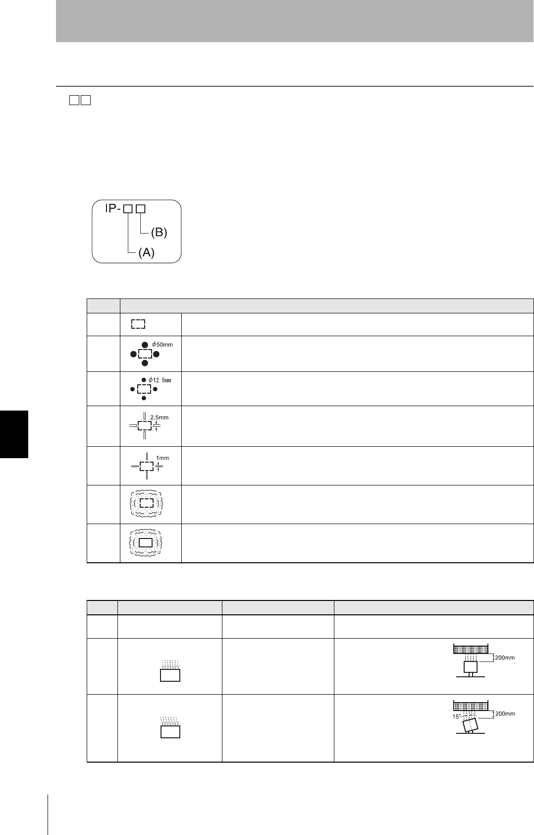
Protective Construction
IP- is governed by the test methods described below. Check in advance the seal characteristics under
the actual environment and conditions of use.
IP is the abbreviation of International Protection.
■IEC (International Electrotechnical Commission)
Standard (IEC60529: 1989-11)
(A) First numeral in code: Class of protection against entry of solid foreign material
(B) Second numeral of code: Class of protection against the entry of water
Class Degree of protection
0 No protection
1 Protected against access by solid objects with a diameter of 50 mm or greater (e.g., human hands).
2 Protected against access by solid objects with a diameter of 12.5 mm or greater (e.g., fingers).
3 Protected against access by wires and solid bodies with a diameter of 2.5 mm or greater.
4 Protected against access by wires and solid bodies with a diameter of 1 mm or greater.
5 Entry of volumes of dust that would cause difficulties in normal operation of devices or compromise
safety is prevented.
6 Entry of dust is prevented.
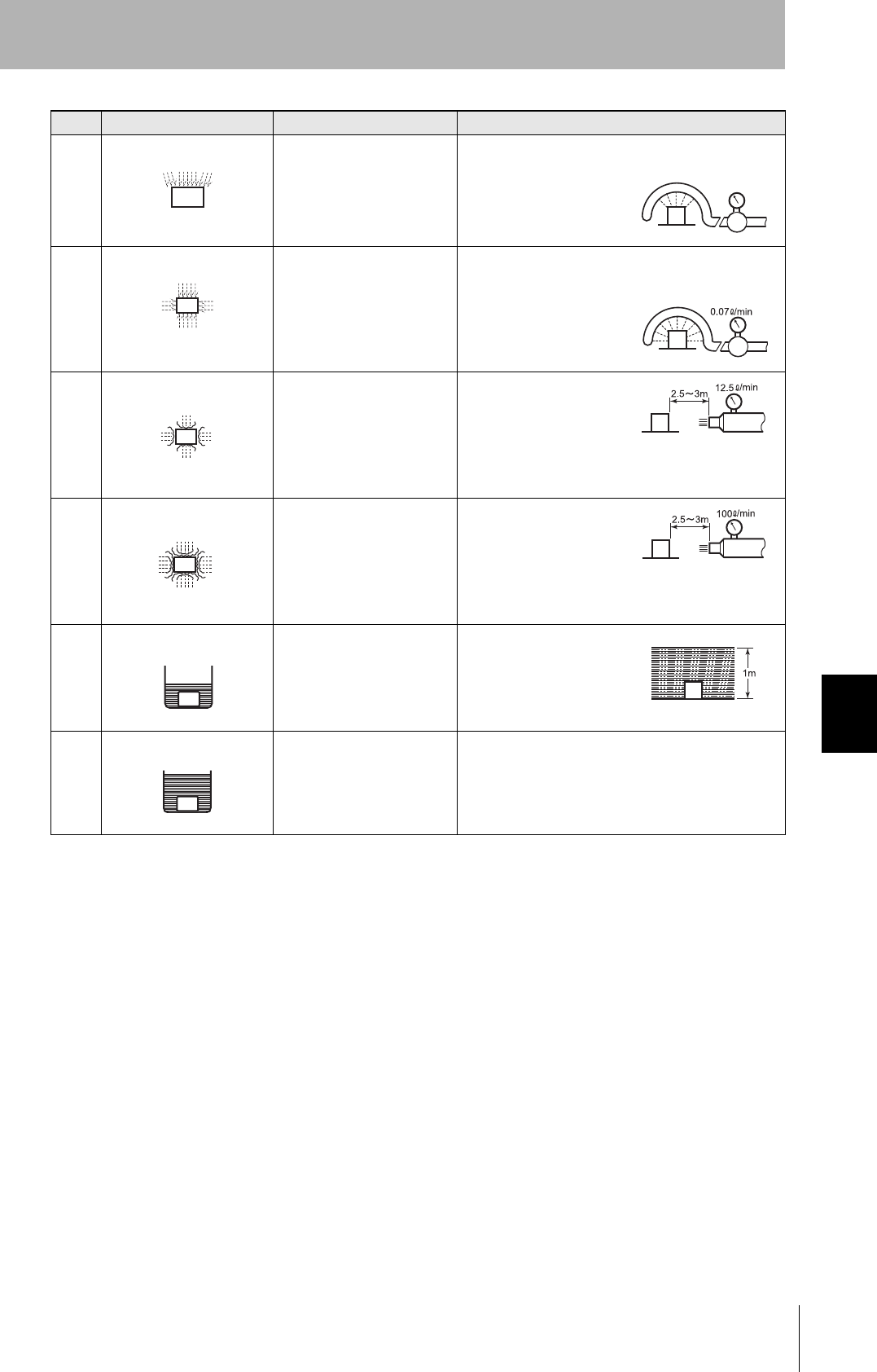
Class Degree of protection Outline of test methods (tests using water)
0 No special protection No protection against the
entry of water.
No test
1 Protection against droplets
of water
The product suffers no ill
effects from droplets of water
falling vertically onto it.
Water droplets are
sprayed onto the product
from directly above for 10
minutes by water droplet
exposure test apparatus.
2 Protection against droplets
of water
The product suffers no ill
effects from droplets of water
directed at it at an angle of up
to 15° to vertical.
The water droplet expo-
sure test apparatus is set
to 15° from vertical and
water droplets sprayed
onto the product for 10
minutes (total of 25 min-
utes in each direction).
CIDRW System
User’s Manual
SECTION 7
Protective Construction
SECTION 7
Appendix
115
3 Protection against spraying
water
The product suffers no ill
effects from a water spray
directed at it at up to 60° from
vertical.
Using the test apparatus
shown in the figure to the
right, water is sprayed
from both directions, onto
both sides of the product,
at angles up to 60° from
vertical for 10 minutes.
4 Protection against splashing
water
The product suffers no ill
effects from water splashed
on it from all directions.
Using the test apparatus
shown in the figure to the
right, water is splashed
onto the product from all
directions for 10 minutes.
5 Protection against water
jets
The product suffers no ill
effects from a water jet aimed
directly at it from all directions.
Using the test apparatus
shown in the figure to the
right, a water jet is directed
at the product from all
directions for 1 minute per
square meter of outer cas-
ing, with a minimum total
exposure of 3 minutes.
6 Protection against powerful
jets of water
Water does not enter the
product when a powerful jet of
water is directed at it from all
directions.
Using the test apparatus
shown in the figure to the
right, a water jet is directed
at the product from all
directions for 1 minute per
square meter of outer cas-
ing, with a minimum total
exposure of 3 minutes.
7 Protection against immer-
sion in water
No entry of water on
immersion in water at the
stipulated pressure for the
stipulated time.
Immerse in water for 30
minutes at a depth of 1
meter (when the height of
the apparatus is less than
850 mm).
8 Protection against
immersion in water
The product can be used
while continually immersed in
water.
Depends on arrange-
ments made between the
manufacturer and the user
of the product.
Class Degree of protection Outline of test methods (tests using water)
0.07 L/min.
per hole in the
spray nozzle
0.07 L/min.
per hole in the
spray nozzle
Diameter of spray
nozzle head: 6.3
Diameter of spray
nozzle head: 12.5

116
SECTION 7
Protective Construction
CIDRW System
User’s Manual
SECTION 7
Appendix

Revision History
A manual revision code appears as a suffix to the catalog number on the front cover of the manual.
The following table outlines the changes made to the manual during each revision. Page numbers refer to the previous
version.
Revision code Date Revised content
01 September 2010 Original production
Cat. No. Z308-E1-01
Revision code

Authorized Distributor:
In the interest of product improvement,
specifications are subject to change without notice.
Cat. No. Z308-E1-01
Printed in Japan
0910
© OMRON Corporation 2010 All Rights Reserved.
OMRON Corporation Industrial Automation Company
OMRON ELECTRONICS LLC
One Commerce Drive Schaumburg,
IL 60173-5302 U.S.A.
Tel: (1) 847-843-7900/Fax: (1) 847-843-7787
Contact: www.ia.omron.com
Tokyo, JAPAN
OMRON ASIA PACIFIC PTE. LTD.
No. 438A Alexandra Road # 05-05/08 (Lobby 2),
Alexandra Technopark,
Singapore 119967
Tel: (65) 6835-3011/Fax: (65) 6835-2711
OMRON (CHINA) CO., LTD.
Room 2211, Bank of China Tower,
200 Yin Cheng Zhong Road,
PuDong New Area, Shanghai, 200120, China
Tel: (86) 21-5037-2222/Fax: (86) 21-5037-2200
Regional Headquarters
OMRON EUROPE B.V.
Sensor Business Unit
Carl-Benz-Str. 4, D-71154 Nufringen, Germany
Tel: (49) 7032-811-0/Fax: (49) 7032-811-199