Omron V640HAM11L Carrier ID Reader/Writer (RFID) User Manual Z308 E1 01
Omron Corporation Carrier ID Reader/Writer (RFID) Z308 E1 01
Omron >
Contents
- 1. User manual1(L)
- 2. User manual2(L)
- 3. User manual1(L-ETN)
- 4. User manual2(L-ETN)
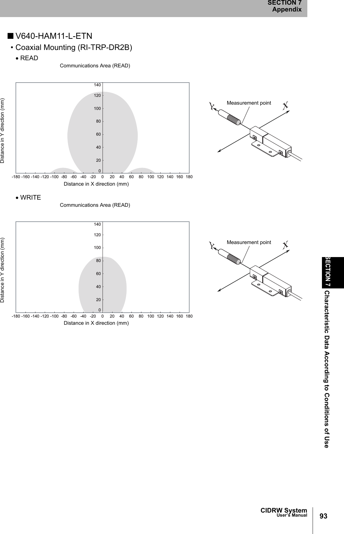
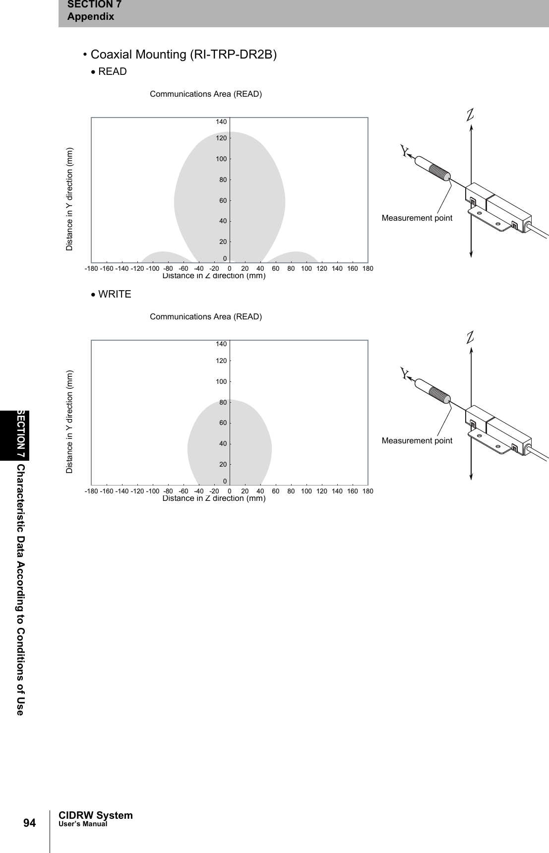
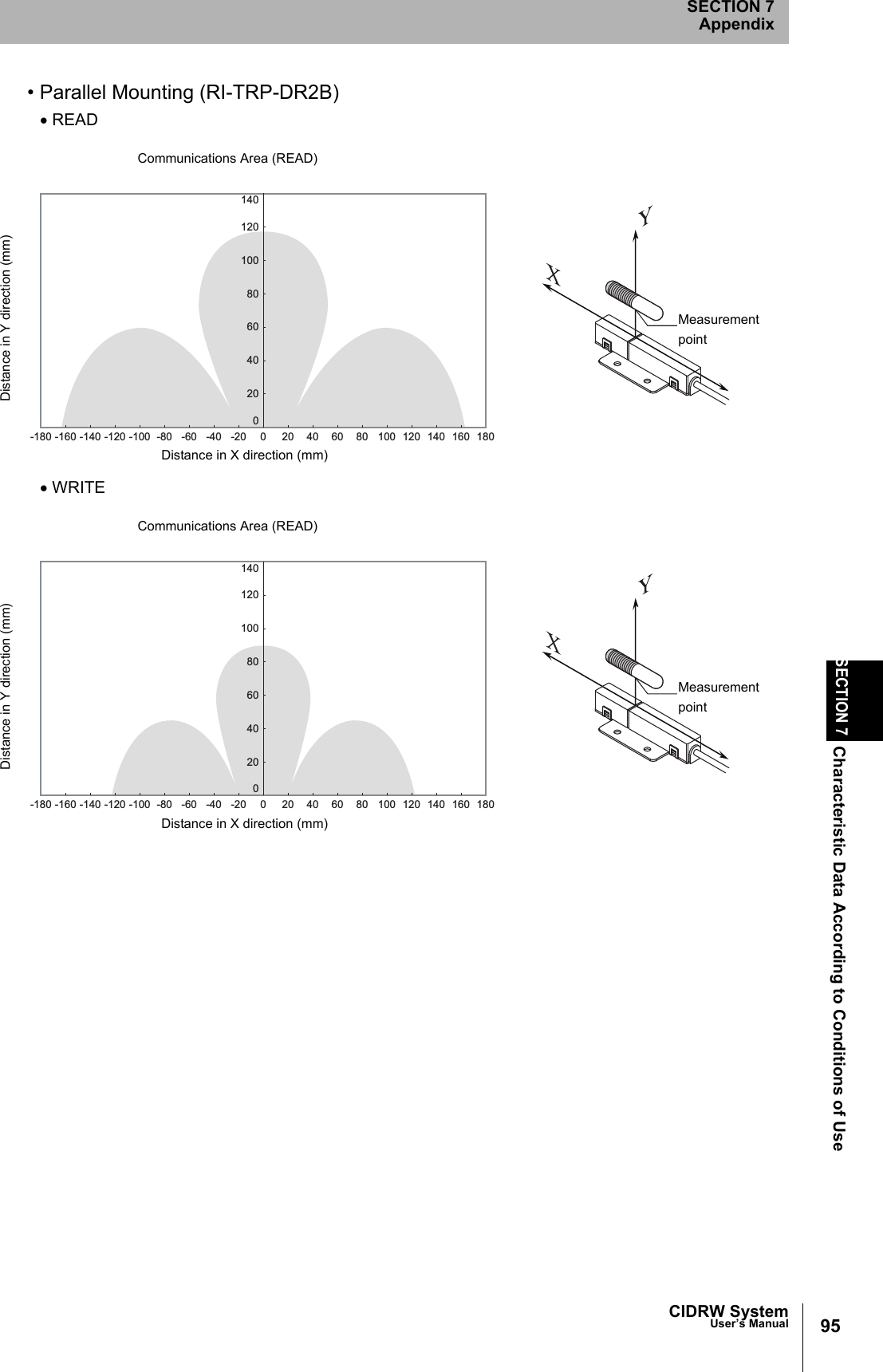
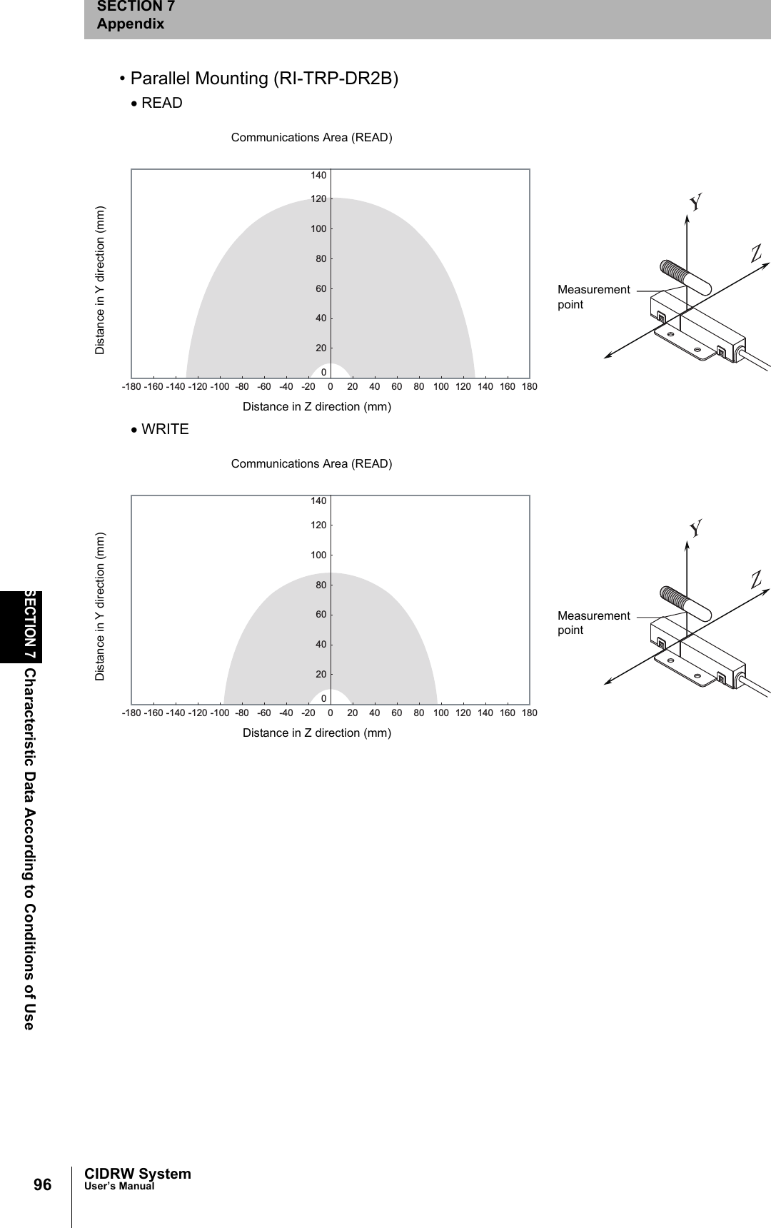
User manual2(L-ETN)
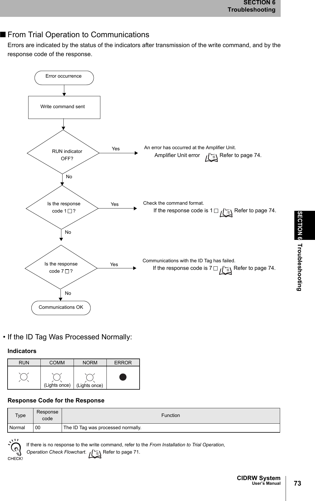
![CIDRW SystemUser’s ManualSECTION 7ASCII Code TableSECTION 7Appendix113ASCII Code TableLeftmostbitsRight-most bitsb8 to b50000 1001 0010 0011 0100 0101 0110 0111 1000 1101 1010 1011 1100 1101 1110 1111b4 to b1RowLine0 12345678910 11 12 13 14 150000 0NUL TC7(DLE)(SP) 0 @ P ` pUndefined Undefined Undefined0001 1TC1(SOH) DC1!1AQaq0010 2TC2(STX) DC2"2BRbr0011 3TC3(ETX) DC3#3CScs0100 4TC4(EOT) DC4$4DTd t0101 5TC5(NEQ) TC8(NAK)%5EUe u0110 6TC6(ACK) TC9(SYN)&6FV f v0111 7BEL TC10(ETB)'7GWgw1000 5FE0(BS) CAN(8HXhx1001 9FE1(HT) EM)9IYiy1010 10FE2(LF) SUB*:JZjz1011 11FE3(VT) ESC+;K[k{1100 12FE4(FF) IS4(FS),<L\ l |1101 13FE5(CR) IS3(GS)-=M]m}1110 14S0 IS2(RS).>N^nÅP1111 15S1 IS1(US)/?O_oDEL](https://usermanual.wiki/Omron/V640HAM11L.User-manual2-L-ETN/User-Guide-1350896-Page-45.png)