Omron V640HAM11L Carrier ID Reader/Writer (RFID) User Manual Z307 E1 01
Omron Corporation Carrier ID Reader/Writer (RFID) Z307 E1 01
Omron >
Contents
- 1. User manual1(L)
- 2. User manual2(L)
- 3. User manual1(L-ETN)
- 4. User manual2(L-ETN)
User manual2(L)
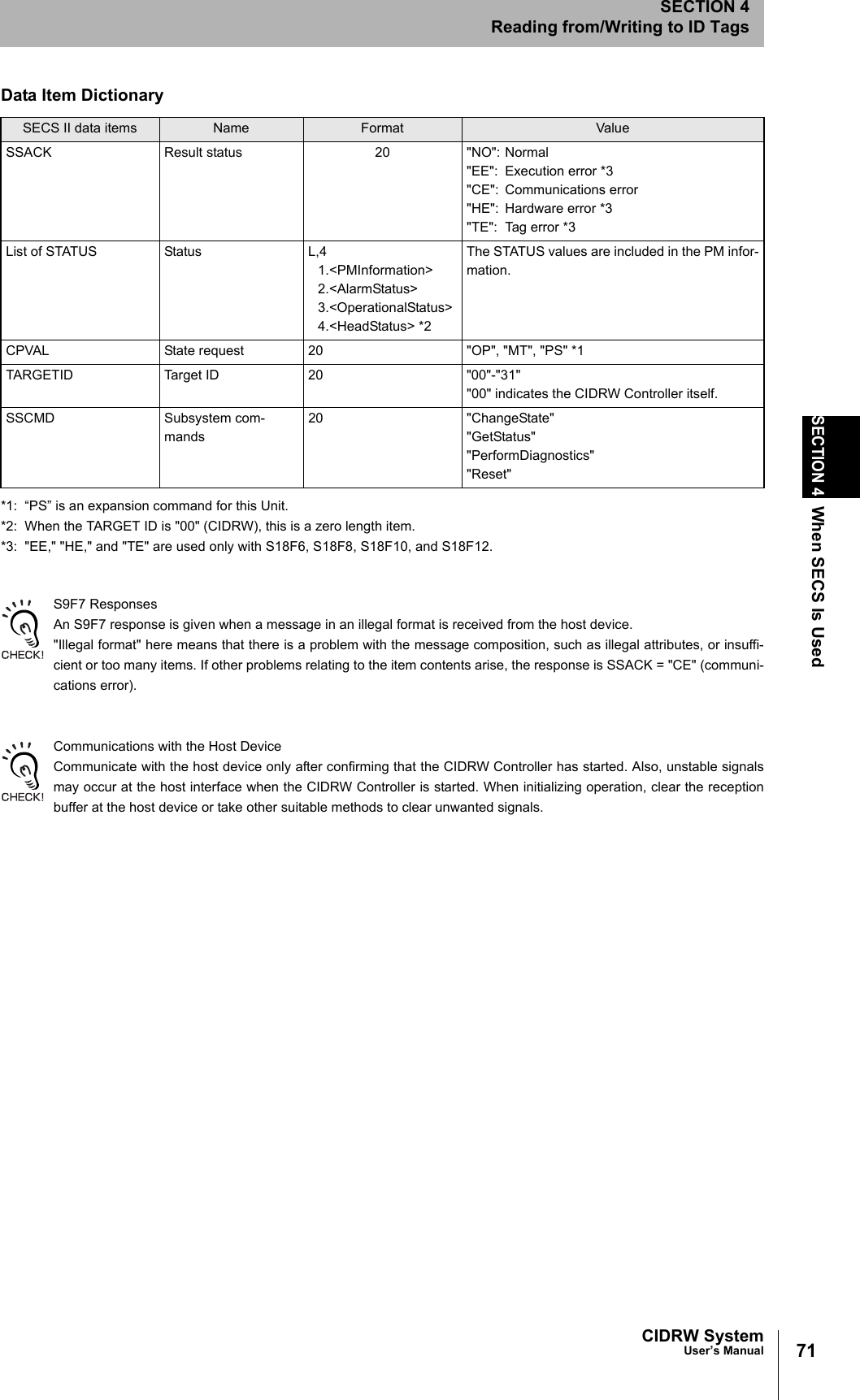

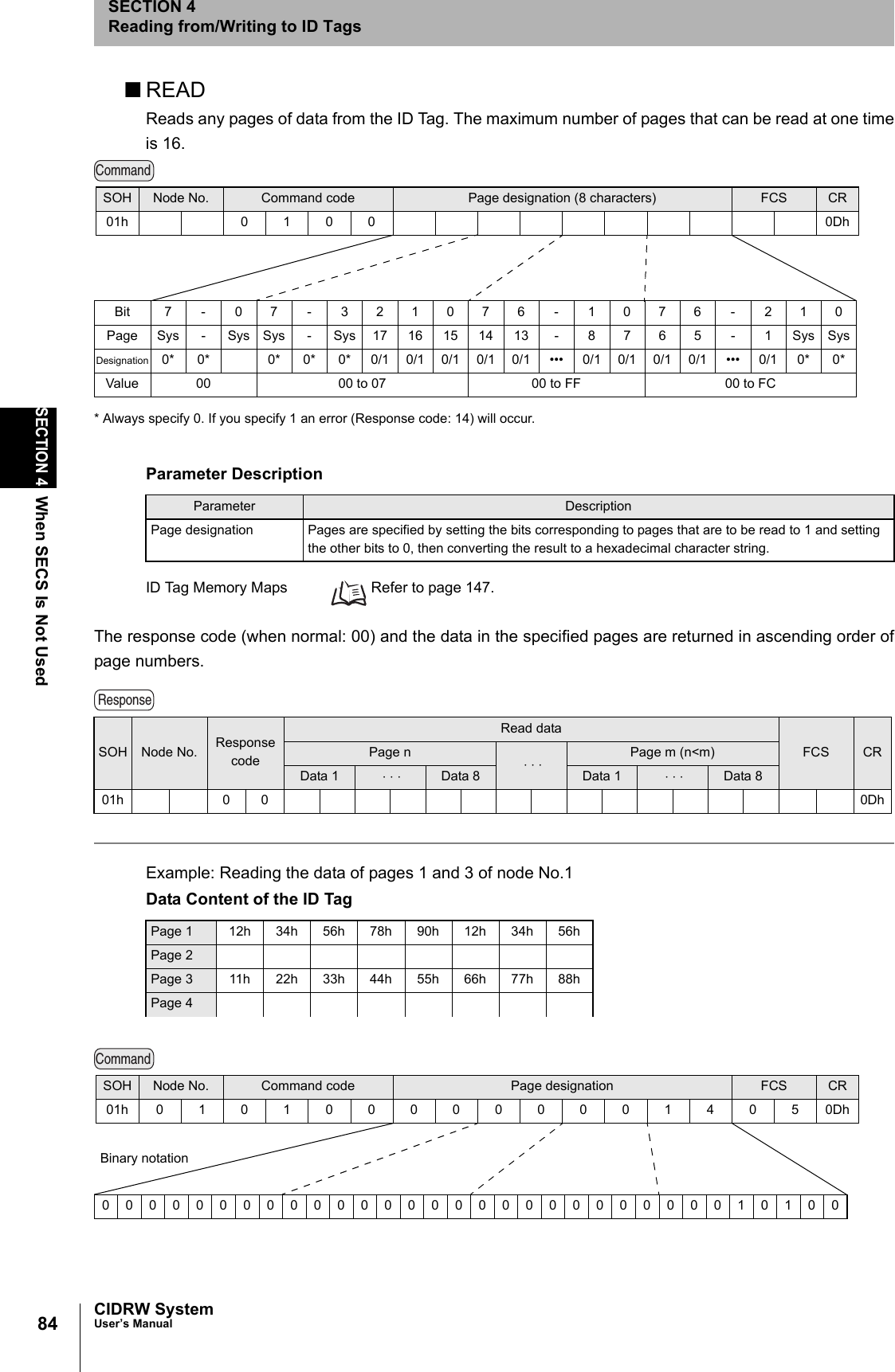
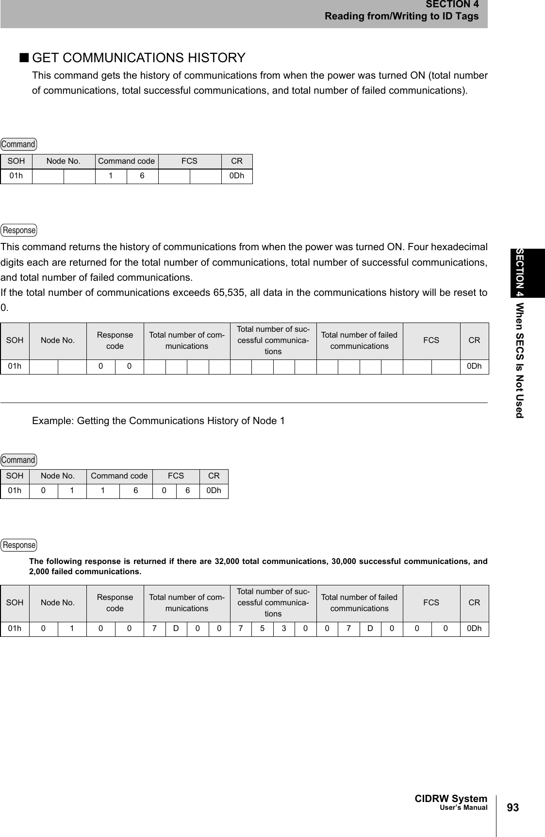
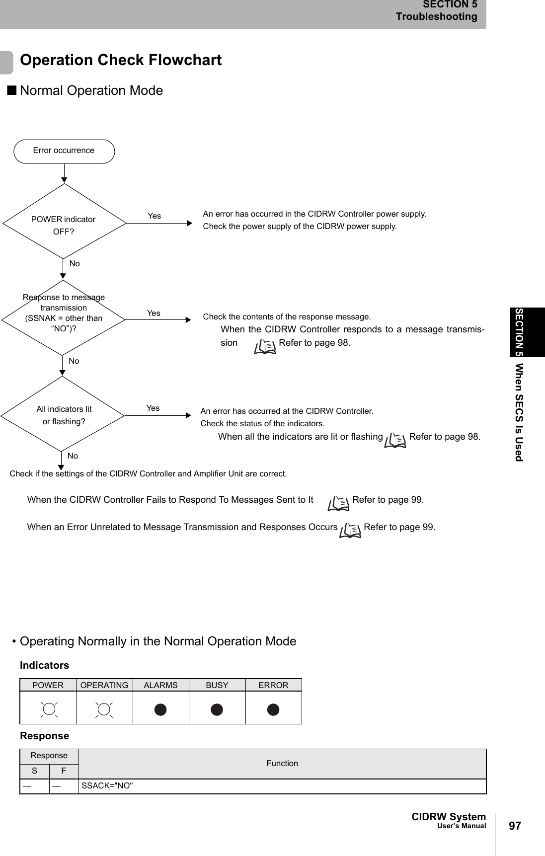
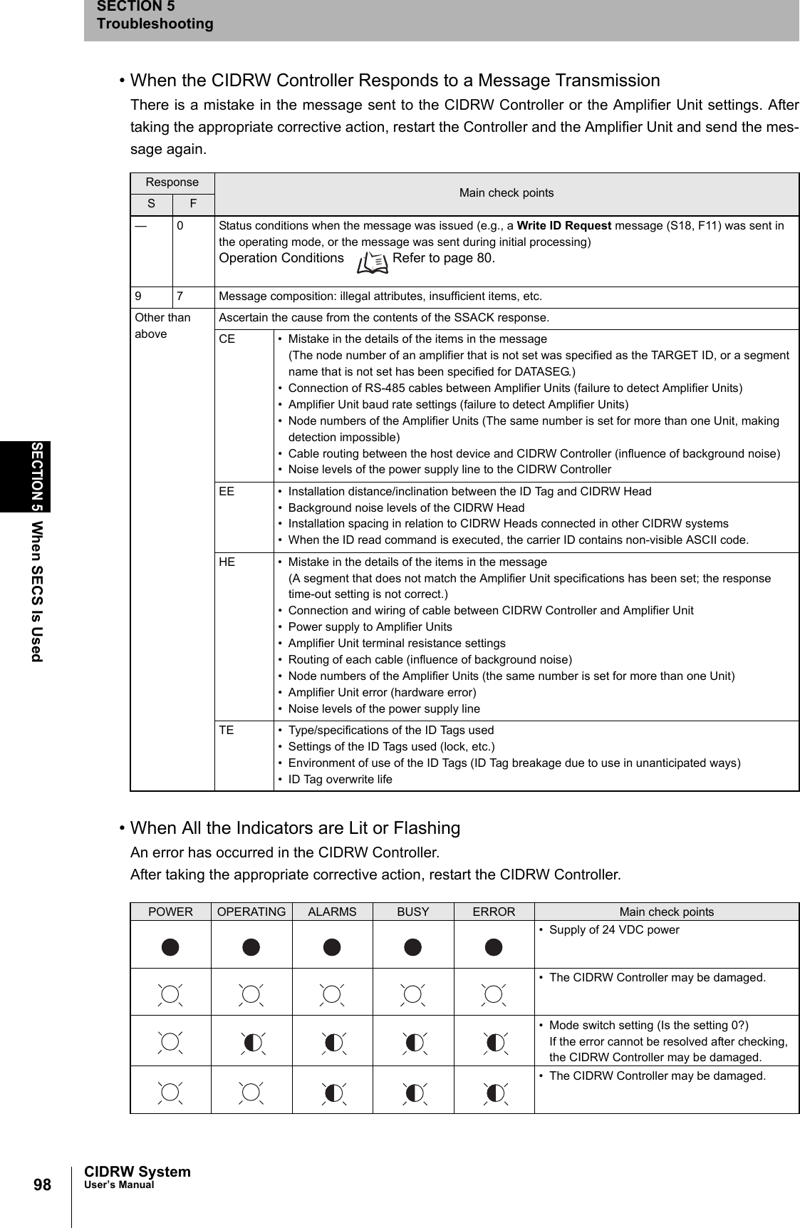
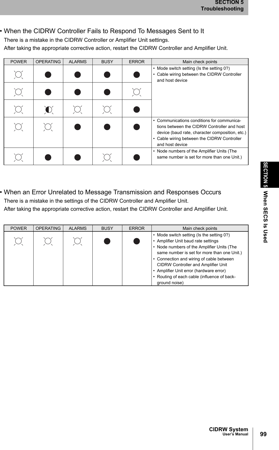
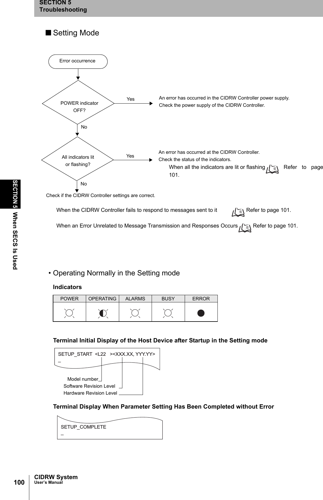
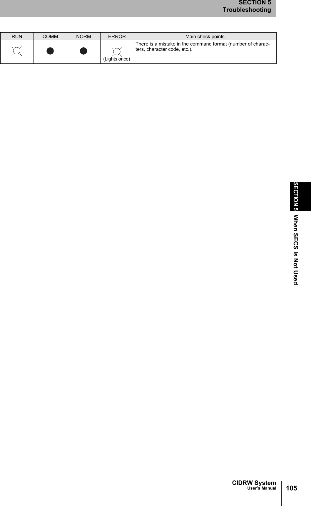
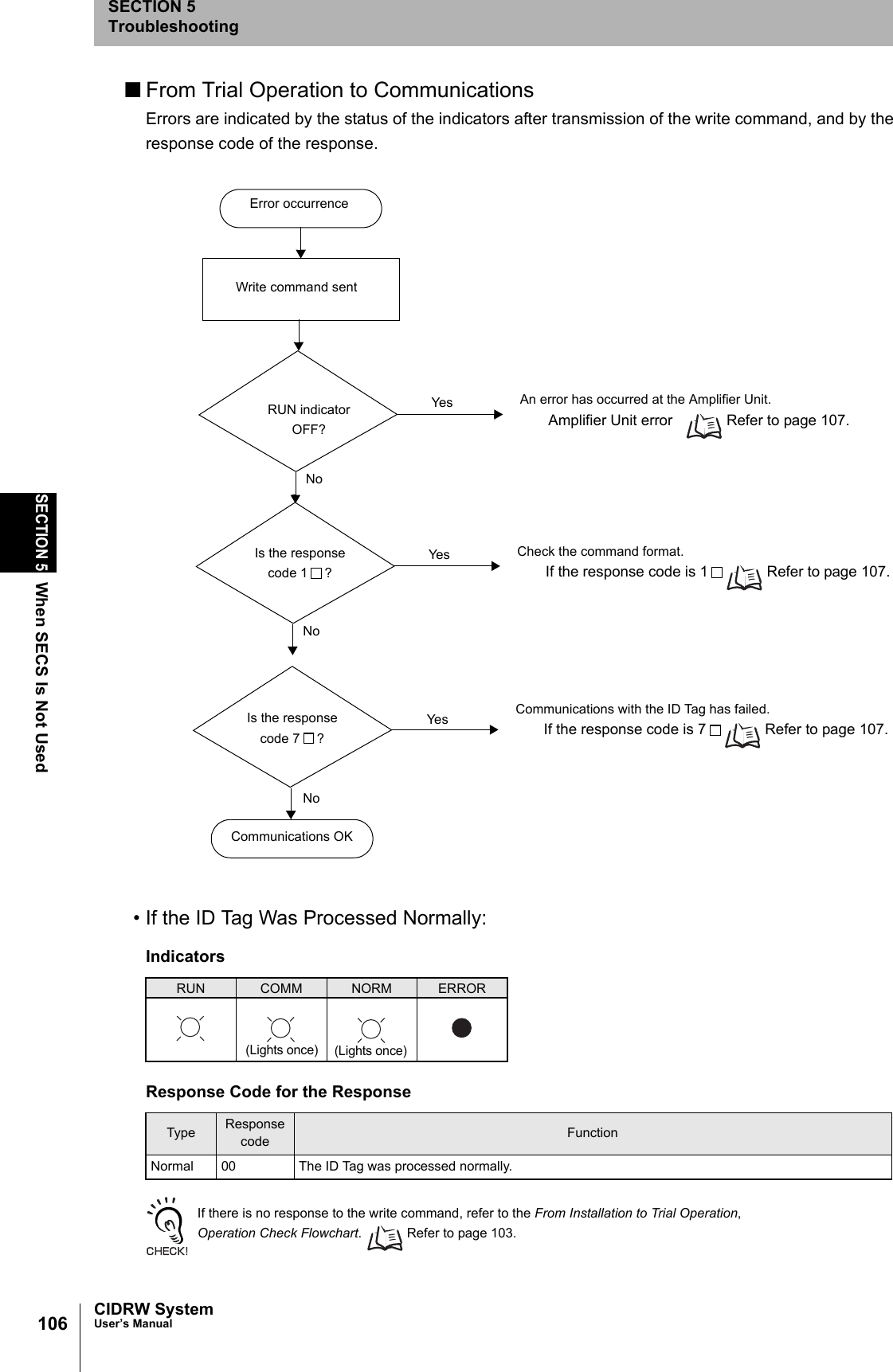
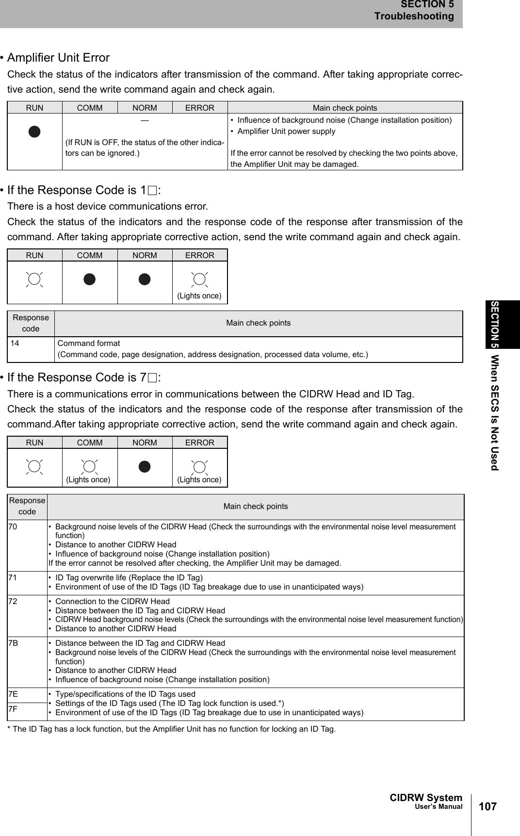
![101CIDRW SystemUser’s ManualSECTION 5When SECS Is UsedSECTION 5Troubleshooting• When All the Indicators Are Lit or FlashingAn error has occurred in the CIDRW Controller. After taking appropriate corrective action, restart the CIDRW Controller and check the indicators.• When the CIDRW Controller Responds to a Message TransmissionThere is a mistake in the CIDRW Controller settings or the sent parameters. After taking appropriate corrective action, restart the CIDRW Controller and check the indicators.• When the CIDRW Controller Fails to Respond To Messages Sent to ItThere is a mistake in the CIDRW Controller settings or the sent parameters. After taking appropriate corrective action, restart the CIDRW Controller and check the indicators.• When an Error Unrelated to Message Transmission and Responses OccursThere is a mistake in the settings of the CIDRW Controller or Amplifier Unit. After taking appropriate corrective action, restart the CIDRW Controller and Amplifier Unit and checkthe indicators.POWER OPERATING ALARMS BUSY ERROR Main check points• Supply of 24 VDC power• The CIDRW Controller may be damaged.• Mode switch setting (Is the setting 3?)If the error cannot be resolved after checking, the CIDRW Controller may be damaged.• The CIDRW Controller may be damaged.POWER OPERATING ALARMS BUSY ERROR Main check points• Sent parameters (Are the parameters correct? Are the settings correct?)Response ContentsSETUP_FAILED [ ] The parameters are not updated. The figure in square brackets [ ] indicates the line number where the error was first detected. If a parity error is detected in the received characters, this figure is [0].POWER OPERATING ALARMS BUSY ERROR Main check points• Transmission parameters (Are the parameters correct?)• Communications conditions for communica-tions between the CIDRW Controller and the host device (baud rate, character composition, etc.)• Mode switch setting (Is the setting 3?)POWER OPERATING ALARMS BUSY ERROR Main check points• Mode switch setting (Is the setting 3?)](https://usermanual.wiki/Omron/V640HAM11L.User-manual2-L/User-Guide-1350879-Page-33.png)