On Track Innovations OTI-SATURN Contactless Smart Card Reader User Manual Revised
On Track Innovations Ltd Contactless Smart Card Reader Users Manual Revised
UserManual.wiki
>
On Track Innovations
>
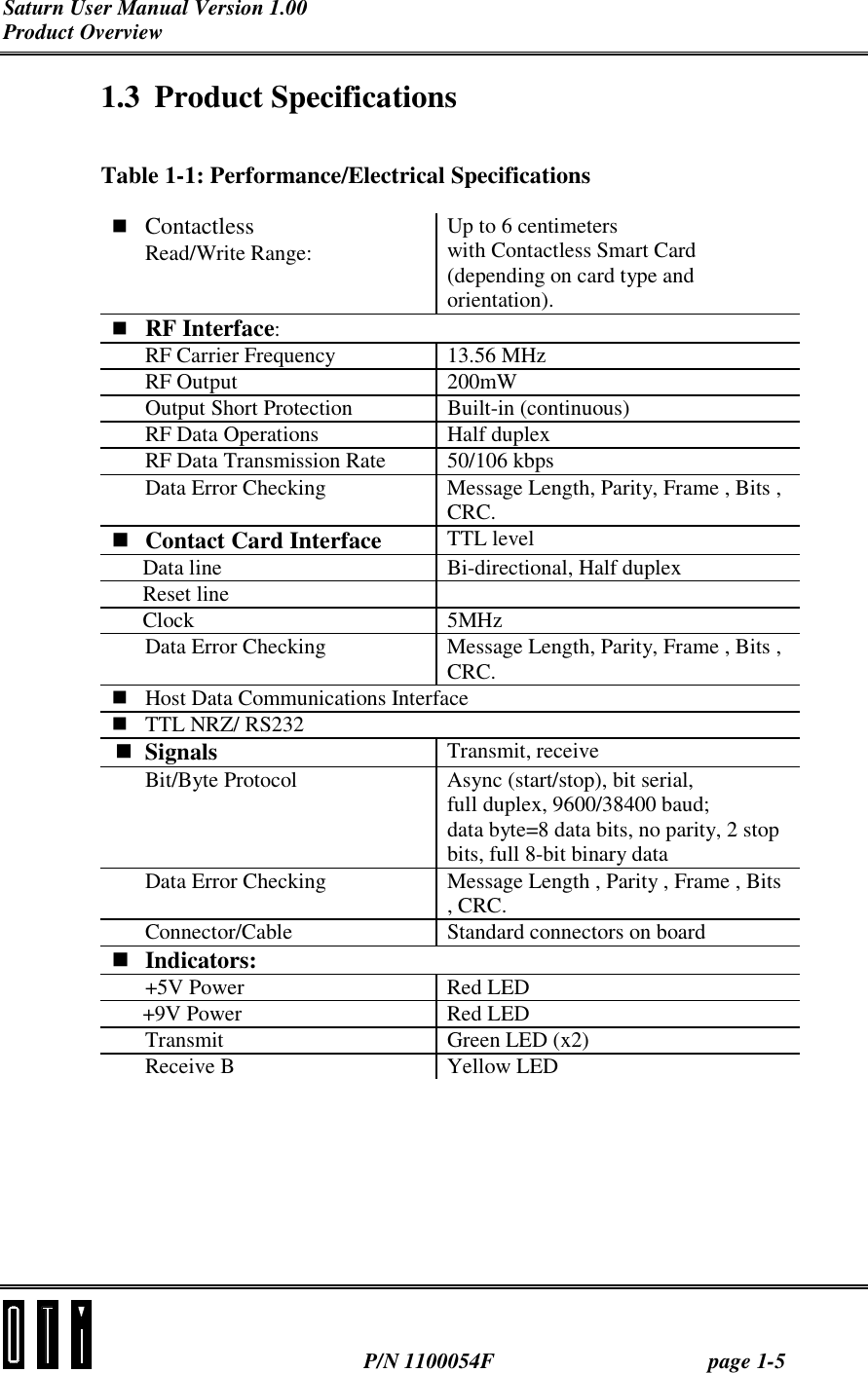
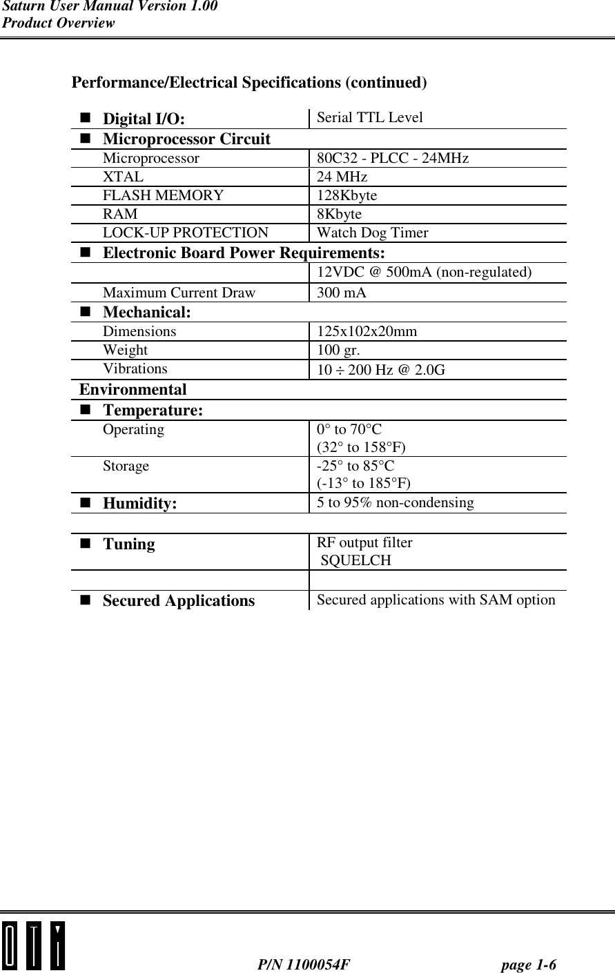
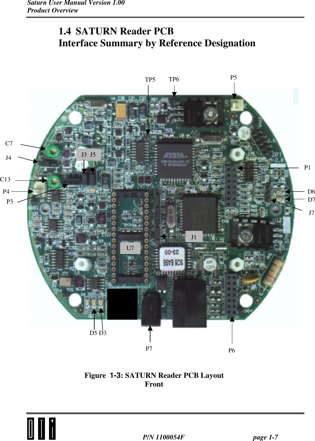
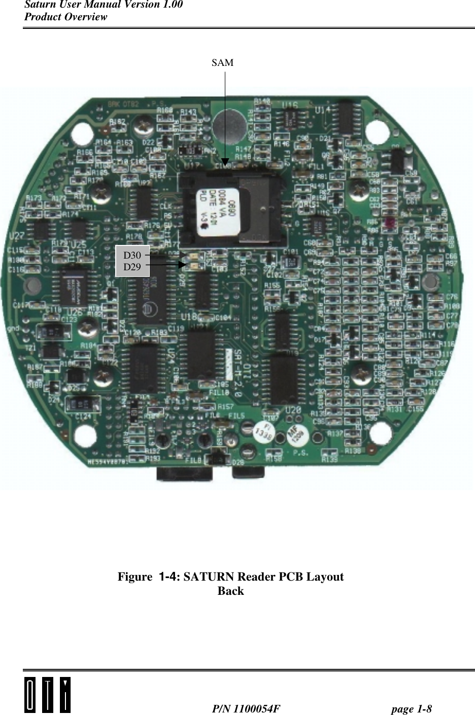
OTI SATURN User Manual
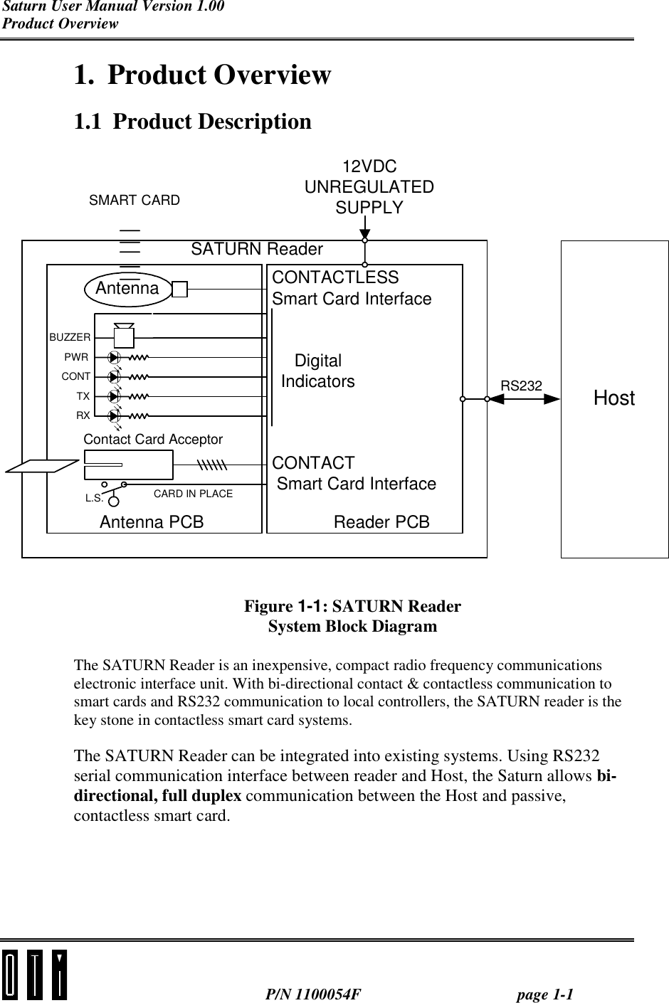
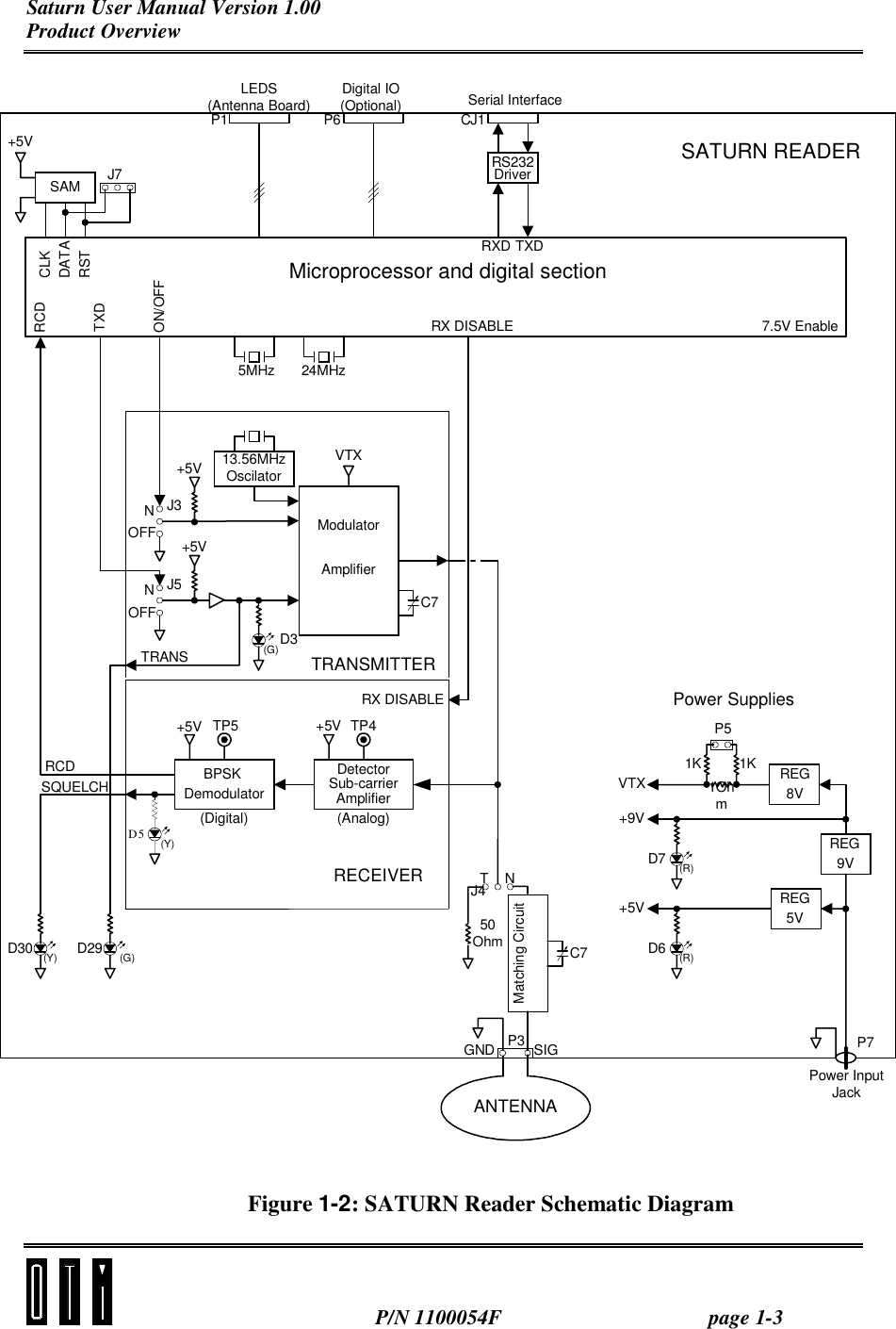
Users Manual Revised
Navigation menu
Upload a User Manual
Namespaces
Wiki Guide
HTML
PDF
Info
Views
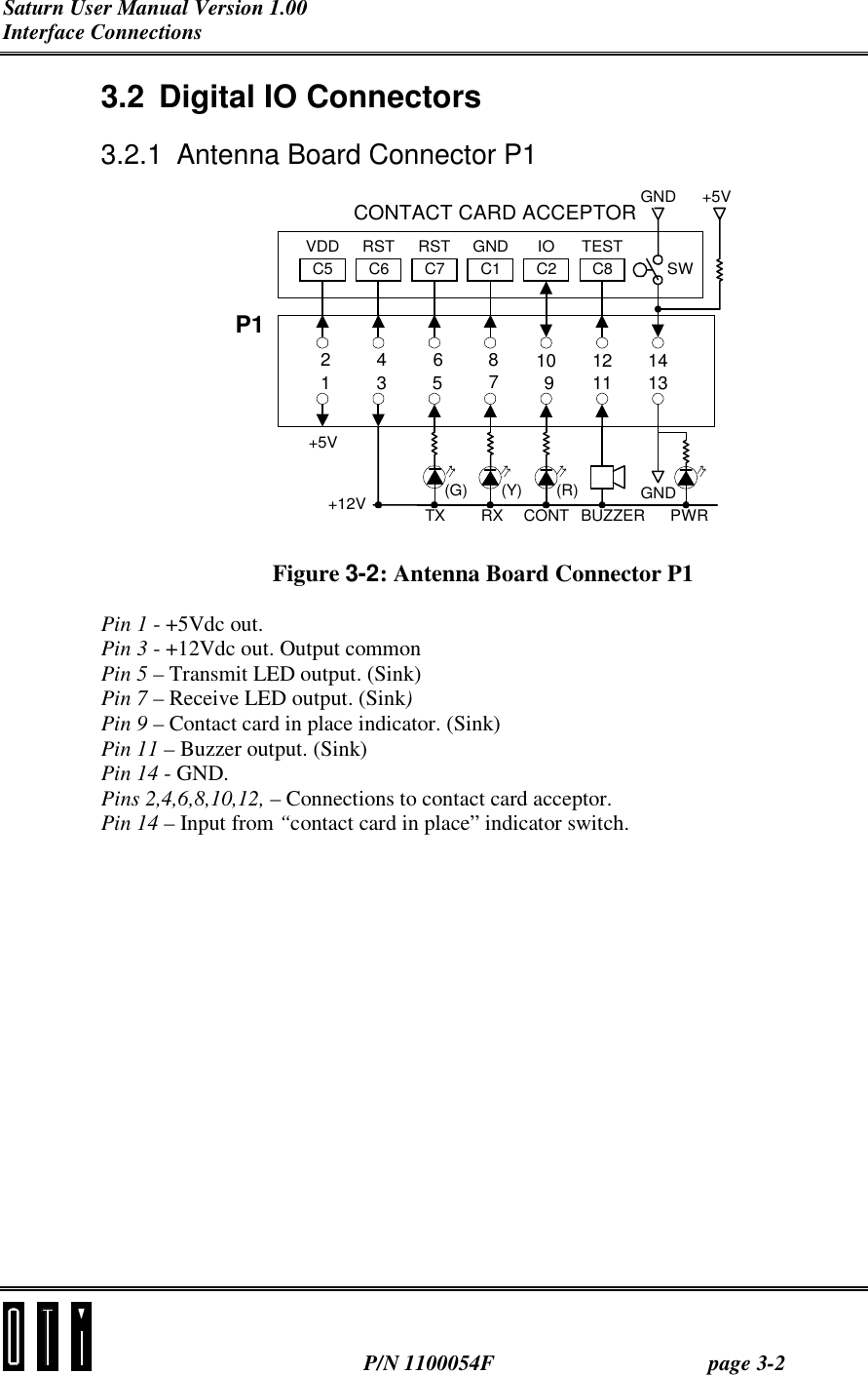
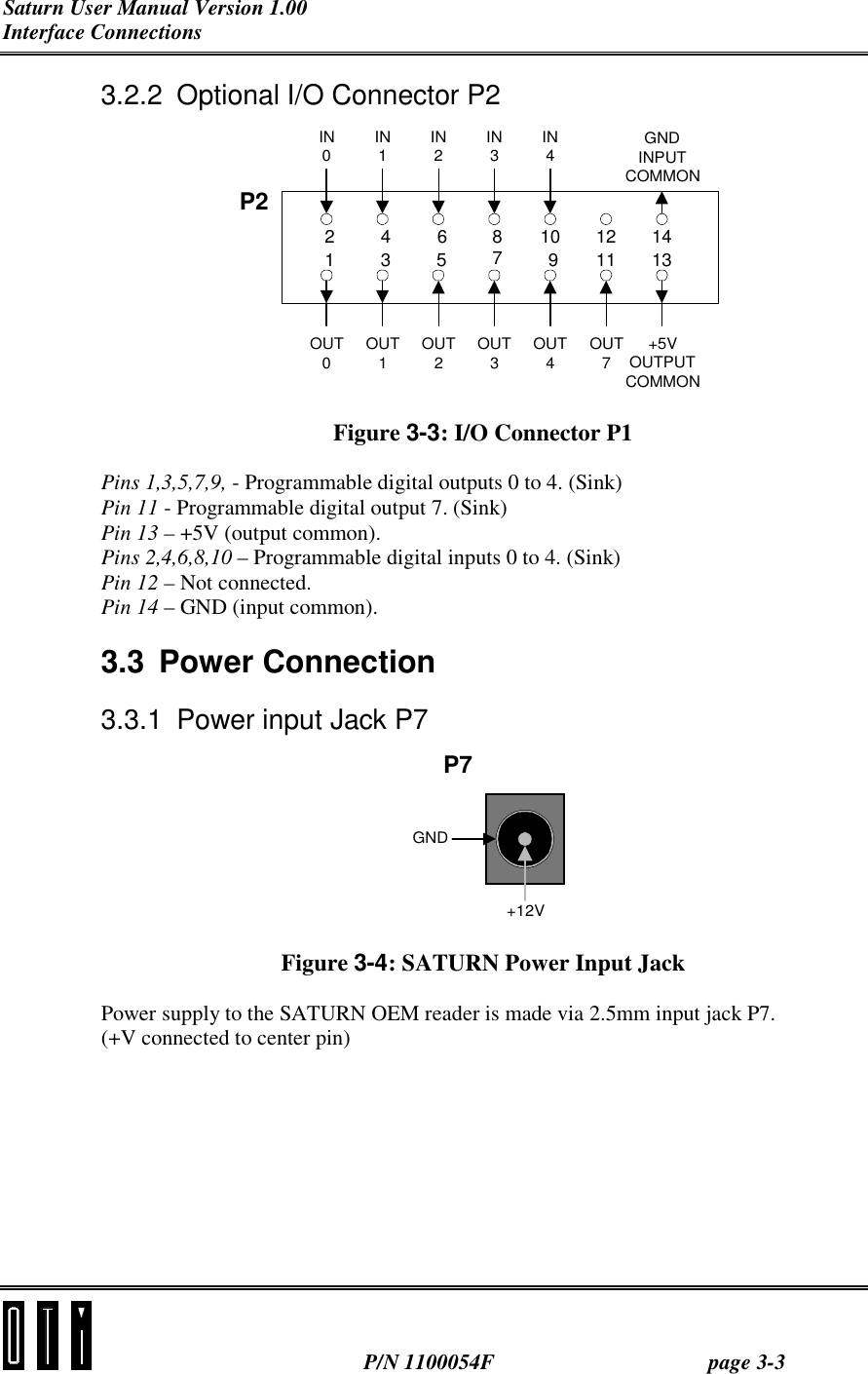
User Manual
Discussion / Help
Navigation