On Track Innovations OTI-SATURN Contactless Smart Card Reader User Manual Revised
On Track Innovations Ltd Contactless Smart Card Reader Users Manual Revised
Users Manual Revised

Saturn User Manual Version 1.00
FCC Compliance
P/N 1100054F page 0
Saturn Reader
User Manual
Version 1.00
On Track Innovations Ltd.
(O T I)
P/N 1100054F

Saturn User Manual Version 1.00
FCC Compliance
P/N 1100054F page 1
FCC Compliance
This device (Reader Saturn 3000) complies with Part 15, of the FCC Rules.
Operation is subject to the following two conditions:
1. This device may not cause harmful interference,
and
2. This device must accept any interference received, including
interference that may cause undesired operation
• NOTE: This equipment has been tested and found to comply
with the limits for a Class B digital device, pursuant to part 15,
subpart C of the FCC Rules. These limits are designed to
provide reasonable protection against harmful interference in a
residential installation. This equipment generates, uses and can
radiate radio frequency energy and, if not installed and used in
accordance with the instructions, may cause harmful
interference to radio communications.
Changes or modifications in this equipment, not expressly approved by the party
responsible for compliance (On Track Innovations Ltd,) could void the user’s
authority to operate the equipment.
FCC ID: JNX-OTI-SATURN
Responsible Party:
OTI America Inc.
1601 South DeAnza Blvd.
Cupertino, CA95014
USA
Phone: 408-252-0333

Saturn User Manual Version 1.00
Table of Contents
P/N 1100054F page 2
Table of Contents
FCC COMPLIANCE......................................................................................................................1
TABLE OF CONTENTS................................................................................................................2
1. PRODUCT OVERVIEW....................................................................................................1-1
1.1 PRODUCT DESCRIPTION ....................................................................................................1-1
1.2 PRODUCT FEATURES.........................................................................................................1-4
1.3 PRODUCT SPECIFICATIONS................................................................................................1-5
1.4 SATURN READER PCB INTERFACE SUMMARY BY REFERENCE DESIGNATION...............1-7
1.4.1 Connectors .............................................................................................................1-9
1.4.2 LEDs.......................................................................................................................1-9
1.4.3 Jumpers ................................................................................................................1-10
1.4.4 Tuning Capacitors................................................................................................1-10
1.4.5 Test Points............................................................................................................1-10
1.4.6 SAM......................................................................................................................1-10
2. PCB MECHANICAL INSTALLATION ..........................................................................2-1
2.1 PCB MOUNTING DIMENSIONS..........................................................................................2-1
2.2 PCB MOUNTING INSTRUCTIONS.......................................................................................2-1
2.2.1 Enclosure................................................................................................................2-1
2.2.2 Ventilation ..............................................................................................................2-1
3. INTERFACE CONNECTIONS.........................................................................................3-1
3.1 COMMUNICATION CONNECTORS.......................................................................................3-1
3.1.1 RS232 Serial Interface connector CJ1 ...................................................................3-1
3.2 DIGITAL IO CONNECTORS ................................................................................................3-2
3.2.1 Antenna Board Connector P1 ................................................................................3-2
3.2.2 Optional I/O Connector P2 ....................................................................................3-3
3.3 POWER CONNECTION........................................................................................................3-3
3.3.1 Power input Jack P7...............................................................................................3-3
4. JUMPER & MODE SETTINGS........................................................................................4-1
4.1 TRANSMISSION JUMPER J1................................................................................................4-1

Saturn User Manual Version 1.00
Table of Contents
P/N 1100054F page 3
4.2 TRANSMISSION MODULATION JUMPER J3.........................................................................4-1
4.3 ANTENNA JUMPER J4........................................................................................................4-1
4.4 TRANSMITTER CARRIER JUMPER J5..................................................................................4-1
4.5 NORMAL OPERATION JUMPER SETTINGS ..........................................................................4-2
4.6 SELECTION OF OPERATING MODE AND BAUD RATE.........................................................4-2
5. FLASH MEMORY PROGRAMMING ............................................................................5-1
5.1 INTRODUCTION .................................................................................................................5-1
5.2 PC REQUIREMENTS...........................................................................................................5-1
5.3 PROGRAMMER SOFTWARE INSTALLATION........................................................................5-1
5.4 HARDWARE SETUP ...........................................................................................................5-1
5.5 PROGRAMMING.................................................................................................................5-2
5.5.1 Flash Memory Files................................................................................................5-2
5.5.2 Programming Procedure........................................................................................5-2
5.6 HELP.................................................................................................................................5-2
Saturn User Manual Version 1.00
Product Overview
P/N 1100054F page 1-1
1. Product Overview
1.1 Product Description
Host
SMART CARD
12VDC
UNREGULATED
SUPPLY
RS232
RX
TX
CONT
PWR
BUZZER
Reader PCB
CARD IN PLACE
CONTACTLESS
Smart Card Interface
L.S.
Antenna
Contact Card Acceptor
Antenna PCB
CONTACT
Smart Card Interface
SATURN Reader
Digital
Indicators
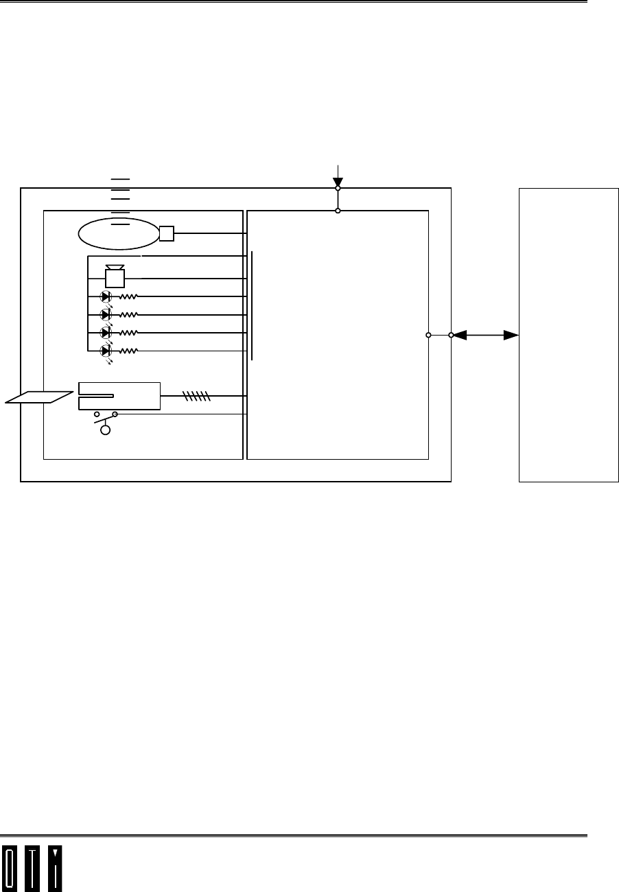
Figure 1-1: SATURN Reader
System Block Diagram
The SATURN Reader is an inexpensive, compact radio frequency communications
electronic interface unit. With bi-directional contact & contactless communication to
smart cards and RS232 communication to local controllers, the SATURN reader is the
key stone in contactless smart card systems.
The SATURN Reader can be integrated into existing systems. Using RS232
serial communication interface between reader and Host, the Saturn allows bi-
directional, full duplex communication between the Host and passive,
contactless smart card.

Saturn User Manual Version 1.00
Product Overview
P/N 1100054F page 1-2
The SATURN OEM Reader Board serves as a smart interface unit between the
application controller and:
1. ISO14443 Type B Contactless smart cards.
2. SAM Secured Applications Module
3. Contact smart cards.
Contact cards
The SATURN provides interface (T=0 and T=1) between the contact card and the
Application Controller. Communication with the contact card acceptor is TTL NRZ.
Contactless Cards
At the Host’s command, the SATURN generates and modulates a 13.56 MHz carrier
signal for the transmission of power, commands and data to an in-range smart card.
Read and write operations have equal data rates and range.
Secured Transactions
Secured Purse to Purse transactions can be achieved either between a Contact card and
a Contactless card or between cards (contact or contactless) and an “on board” SAM
Secured Applications Module
Indicator LEDs
Nine on board indicator LEDs are provided. (see 1.4.2 )
Digital IO
The Saturn provides interface to an external contact card acceptor as well as external
indication LEDS and user configurable sink type digital IO.
Saturn User Manual Version 1.00
Product Overview
P/N 1100054F page 1-3
D5 (Y)
+5V +5V
Detector
Sub-carrier
Amplifier
TP4TP5
(Analog)(Digital)
BPSK
Demodulator
RECEIVER
D3
(G)
N
OFF
N
+5V
J5
J3
OFF
13.56MHz
Oscilator
VTX
TRANSMITTER
Modulator
Amplifier
C7
D29 (G)
D30 (Y)
RCD
NT
J4
SAM
CLK
DATA
RST
J7
+5V
Matching Circuit
50
Ohm
GND SIG
P3
ANTENNA
RS232
Driver
RXD TXD
CJ1
Serial Interface
P1 P6
LEDS
(Antenna Board) Digital IO
(Optional)
Microprocessor and digital section
REG
8V
1K1K
1Oh
m
P5
(R)
D7 REG
9V
(R)
D6
REG
5V
+5V
+9V
VTX
P7
Power Input
Jack
Power Supplies
SATURN READER
RX DISABLE 7.5V Enable
+5V
C7
RX DISABLE
5MHz 24MHz
TXD
ON/OFF
RCD
SQUELCH
TRANS
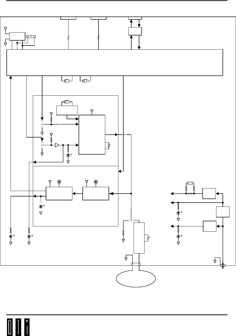
Figure 1-2: SATURN Reader Schematic Diagram

Saturn User Manual Version 1.00
Product Overview
P/N 1100054F page 1-4
1.2 Product Features
! Bi-directional radio frequency interface between Host and Contactless Smart Cards
! Bi-directional interface to Contact Smart Cards
! Flexible, software configurable microcomputer-based design.
! Integrated, sophisticated Smart Card Operating System on board.
! High security encryption system (DES/RSA) in the board’s Operating System (with
SAM option on-board).
! 13.56 MHz transmission frequency conforming to ISO 14443 standard.
! ISO 14443 Type B transmission of commands and data to/from the card.
! Equidistant read/write transaction operation.
! Proximity range - up to 6 cm.
! Signal penetrates virtually any non-conductive material - no contact or line-of-sight
required.
! Bi-directional data transmission from/to the EYECON at 50/106 kbps.
! RS232 Communications interface to Host controller.
! SAM “on-board” option.
! Simultaneous transmission of power and bi-directional read write messages,
through its antenna, to the passive smart card.
!
Indicator LEDs for Power, Card Detected, RF Transmit/ Receive.
!
Flash programmable digital IO.
!
Operating temperature range 0°C to 70°C (32°F to 158°F).
! Single 12V 500mA non-regulated power supply.
! Firmware stored in on-line programmable Flash memory.

Saturn User Manual Version 1.00
Product Overview
P/N 1100054F page 1-5
1.3 Product Specifications
Table 1-1: Performance/Electrical Specifications
!
Contactless
Read/Write Range:
Up to 6 centimeters
with Contactless Smart Card
(depending on card type and
orientation).
!
RF Interface:
RF Carrier Frequency 13.56 MHz
RF Output 200mW
Output Short Protection Built-in (continuous)
RF Data Operations Half duplex
RF Data Transmission Rate 50/106 kbps
Data Error Checking Message Length, Parity, Frame , Bits ,
CRC.
! Contact Card Interface TTL level
Data line Bi-directional, Half duplex
Reset line
Clock 5MHz
Data Error Checking Message Length, Parity, Frame , Bits ,
CRC.
! Host Data Communications Interface
! TTL NRZ/ RS232
! Signals Transmit, receive
Bit/Byte Protocol Async (start/stop), bit serial,
full duplex, 9600/38400 baud;
data byte=8 data bits, no parity, 2 stop
bits, full 8-bit binary data
Data Error Checking Message Length , Parity , Frame , Bits
, CRC.
Connector/Cable Standard connectors on board
!
Indicators:
+5V Power Red LED
+9V Power Red LED
Transmit Green LED (x2)
Receive B Yellow LED

Saturn User Manual Version 1.00
Product Overview
P/N 1100054F page 1-6
Performance/Electrical Specifications (continued)
!
Digital I/O: Serial TTL Level
! Microprocessor Circuit
Microprocessor 80C32 - PLCC - 24MHz
XTAL 24 MHz
FLASH MEMORY 128Kbyte
RAM 8Kbyte
LOCK-UP PROTECTION Watch Dog Timer
! Electronic Board Power Requirements:
12VDC @ 500mA (non-regulated)
Maximum Current Draw 300 mA
! Mechanical:
Dimensions 125x102x20mm
Weight 100 gr.
Vibrations 10 ÷ 200 Hz @ 2.0G
Environmental
! Temperature:
Operating 0° to 70°C
(32° to 158°F)
Storage -25° to 85°C
(-13° to 185°F)
!
Humidity: 5 to 95% non-condensing
! Tuning RF output filter
SQUELCH
! Secured Applications Secured applications with SAM option
Saturn User Manual Version 1.00
Product Overview
P/N 1100054F page 1-7
1.4 SATURN Reader PCB
Interface Summary by Reference Designation
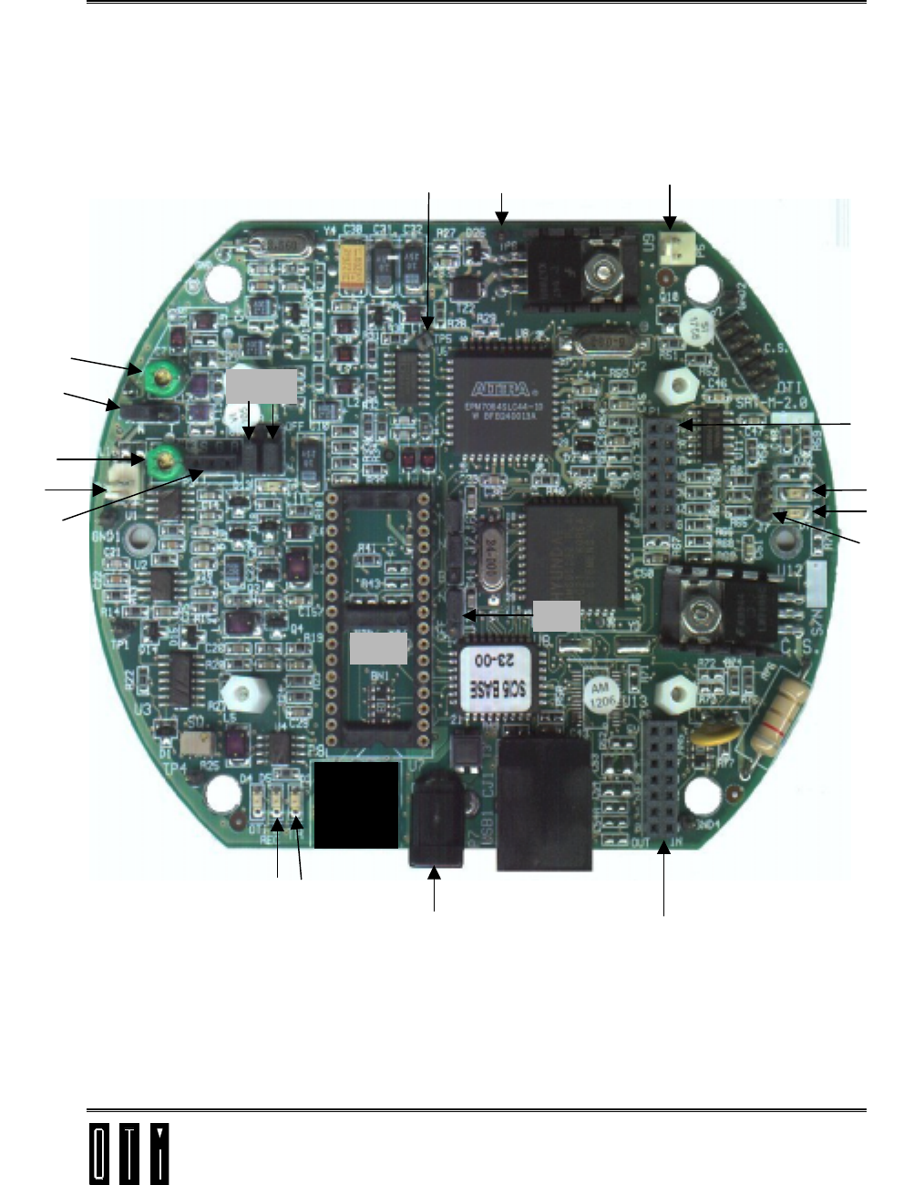
Figure 1-3: SATURN Reader PCB Layout
Front
C7
C13
J4
P3
D5 D3
P7 P6
D7
D6
P1
J7
P5
TP5
J1
J3 J5
P4
TP6
U7
Saturn User Manual Version 1.00
Product Overview
P/N 1100054F page 1-8
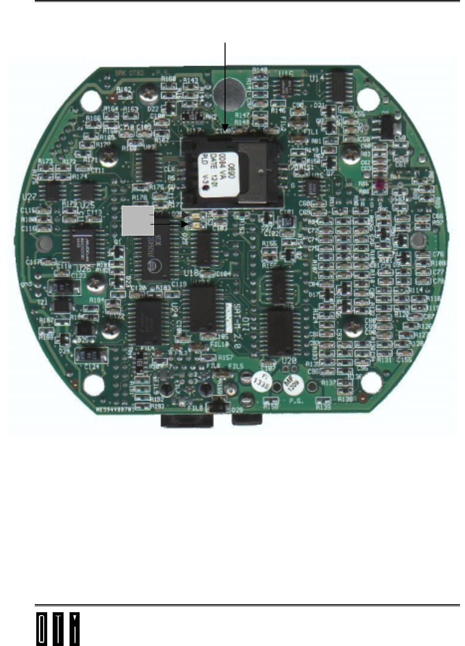
Figure 1-4: SATURN Reader PCB Layout
Back
D30
D29
SAM

Saturn User Manual Version 1.00
Product Overview
P/N 1100054F page 1-9
1.4.1 Connectors
P1 14 pin digital I/O connector to Antenna PCB.
P3 3 pin Antenna connector to Antenna PCB.
P4 2 pin connector for measurement of transmitter voltage.
P5 2 pin connector for measurement of transmitter current.
P6 Optional 14 pin digital I/O connector.
P7 12VDC power input jack connector. (+=Center)
CJ1 RJ45 connector for RS232 serial communication to host.
1.4.2 LEDs
D3 Transmit indicator (green).
D5 Receive indicator (yellow).
D6 +5V (red).
D7 +9V (red)
D29 Transmit indicator (green).
D30 Squelch indicator (yellow).

Saturn User Manual Version 1.00
Product Overview
P/N 1100054F page 1-10
1.4.3 Jumpers
J1 Transmit selector: (MT/CONT/OFF)
J3 Transmitter modulation selector: (MT/CONT/OFF)
J4 Antenna selector:
Normal Transmission to antenna/50Ω load at transmitter output (maintenance only).
J5 Transmitter carrier selector: (MT/CONT/OFF)
J7 Optional connection to external SAM.
1.4.4 Tuning Capacitors
C7 Transmitter tuning.
C13 Antenna matching variable capacitor VCp
1.4.5 Test Points
TP5 Squelch measuring point.
TP6 Received data input to µP measuring point.
1.4.6 SAM
SAM Secured Applications Module.
Saturn User Manual Version 1.00
PCB Mechanical Installation
P/N 1100054F page 2-1
2. PCB Mechanical Installation
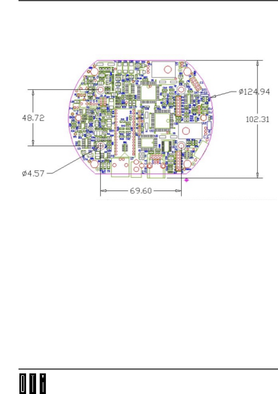
2.1 PCB Mounting Dimensions
Figure 2-1: PCB Mounting Drawing
2.2 PCB Mounting Instructions
2.2.1 Enclosure
The SATURN OEM Reader should be mounted in a protective enclosure. The Reader
Board has 4x4.57 mm diameter mounting holes. If mounted on a metallic surface,
spacers are required to prevent contact between the Reader Board and the metallic
surface.
The reader can be mounted directly on to the main controller motherboard. For this
option, the pins of connectors P1and P6 can be connected to the bottom of the board to
enable piggyback mounting of the reader PCB.
2.2.2 Ventilation
The SATURN OEM Reader Board does not require ventilation for component cooling
purposes.
All dimensions are in millimeters
Saturn User Manual Version 1.00
Interface Connections
P/N 1100054F page 3-1
3. Interface Connections
3.1 Communication Connectors
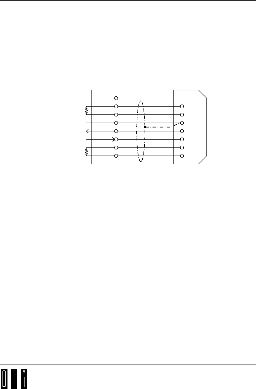
3.1.1 RS232 Serial Interface connector CJ1
1
2
3
4
5
6
7
8
4
6
5
3
2
7
8
DTR
DSR
GND
RXD
TXD
CTS
RTS
DTR
DSR
GND
TXD
RXD
RTS
CTS
Host
DB9 Female
Connector
Saturn
9 Pos. RJ45
Connector
Optional
Optional
Figure 3-1: RS232 Serial Interface connector CJ1
CJ1 RJ45 type connector for RS232/TTL serial communication to Host.
Note: CTS is shorted to RTS and DTR is shorted to CD on the SATURN PCB.
Saturn User Manual Version 1.00
Interface Connections
P/N 1100054F page 3-2
3.2 Digital IO Connectors
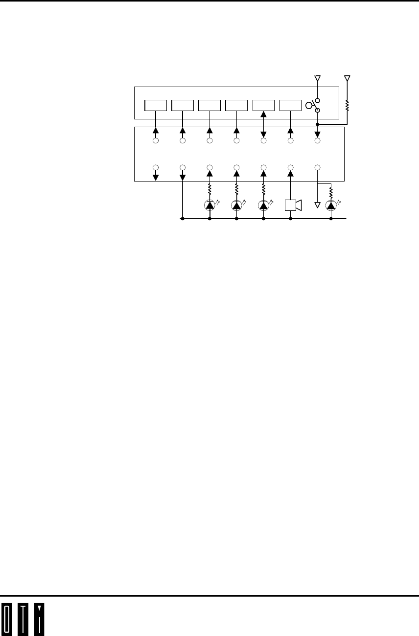
3.2.1 Antenna Board Connector P1
24
13
68
5710
9
12
11
14
13
GND
RXTX
+5V
+12V (G) (Y) (R)
CONT BUZZER
C5 C6 C7 C1 C2 C8 SW
+5VGND
VDD RST RST GND IO TEST
CONTACT CARD ACCEPTOR
P1
PWR
Figure 3-2: Antenna Board Connector P1
Pin 1 - +5Vdc out.
Pin 3 - +12Vdc out. Output common
Pin 5 – Transmit LED output. (Sink)
Pin 7 – Receive LED output. (Sink)
Pin 9 – Contact card in place indicator. (Sink)
Pin 11 – Buzzer output. (Sink)
Pin 14 - GND.
Pins 2,4,6,8,10,12, – Connections to contact card acceptor.
Pin 14 – Input from “contact card in place” indicator switch.
Saturn User Manual Version 1.00
Interface Connections
P/N 1100054F page 3-3
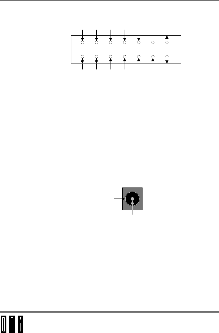
3.2.2 Optional I/O Connector P2
24
13
68
5710
9
12
11
14
13
P2
OUT
0OUT
1OUT
2OUT
3OUT
4OUT
7
+5V
OUTPUT
COMMON
IN
0IN
1IN
2IN
3IN
4GND
INPUT
COMMON
Figure 3-3: I/O Connector P1
Pins 1,3,5,7,9, - Programmable digital outputs 0 to 4. (Sink)
Pin 11 - Programmable digital output 7. (Sink)
Pin 13 – +5V (output common).
Pins 2,4,6,8,10 – Programmable digital inputs 0 to 4. (Sink)
Pin 12 – Not connected.
Pin 14 – GND (input common).
3.3 Power Connection
3.3.1 Power input Jack P7
GND
+12V
P7
Figure 3-4: SATURN Power Input Jack
Power supply to the SATURN OEM reader is made via 2.5mm input jack P7.
(+V connected to center pin)

Saturn User Manual Version 1.00
Jumper & Mode Settings
P/N 1100054F page 4-1
4. Jumper & Mode Settings
4.1 Transmission Jumper J1
1) N position - normal microprocessor controlled data transmission.
2) Off position - no RF signal.
3) No jumper - constant RF signal.
4.2 Transmission Modulation Jumper J3
1) Normal position (N) - normal microprocessor controlled data modulation.
2) 80% position (OFF) – Carrier level at 80%.
3) No jumper – Carrier level at 100%.
4.3 Antenna Jumper J4
1) Normal position (N) - transceiver connected to antenna.
2) Resistor position - transceiver connected to 50Ω load.
3) No jumper - Transceiver disconnected.
4.4 Transmitter Carrier Jumper J5
1) Normal position (N) - normal microprocessor controlled carrier transmission.
2) Off position - no carrier transmission.
3) No jumper - constant carrier transmission.

Saturn User Manual Version 1.00
Jumper & Mode Settings
P/N 1100054F page 4-2
4.5 Normal Operation Jumper Settings
1) Jumpers J1, J3, J4 and J5 should be placed in N position
4.6 Selection of Operating Mode and Baud Rate
The operating system mode and baud rate settings may be changed during operation by
transmitting the following ASCII strings:
1) MODE0 - switches from Host Mode to OEM Mode.
MODE0 → Response M0
2) MODE1 - switches from OEM Mode to Host Mode.
MODE1 → Response M1
3) BAUD0 - switches to 9600-baud rate.
BAUD0 → Response B0
4) BAUD1 - switches to 19200-baud rate.
BAUD1 → Response B1

Saturn User Manual Version 1.00
Flash Memory Programming
P/N 1100054F page 5-1
5. Flash Memory Programming
5.1 Introduction
The SATURN OEM reader’s program is stored in it’s non volatile Flash Memory.
Application versions and updates to the SATURN OEM reader’s program, may be
written only at OTI.
The application versions and updates can be programmed into the SATURN OEM
reader’s Flash memory by the customer through use of the Flash Memory Programmer
software, described in the following paragraphs.
5.2 PC requirements
! Flash Memory Programmer software runs on Windows 95 or Windows NT 32bit
operating systems.
! PC should be at least a 486 DX2.
Program loading time depends on the speed of PC.
5.3 Programmer Software Installation
1. Run the setup.exe file from diskette No. 1.
2. Follow the instructions on the PC screen.
5.4 Hardware Setup
1. Connect RS232 cable between PC and SCI interface.
Note: DTR and DSR as well as CTS and RTS in the PC connector should be
shorted. For 25 pin D type connector, short between 4 & 5 and between 6 & 20.
For 9 pin D type connector, short between 4 & 6 and between 7 & 8.
2. Apply power to the reader

Saturn User Manual Version 1.00
Flash Memory Programming
P/N 1100054F page 5-2
5.5 Programming
5.5.1 Flash Memory Files
The flash memory files, written at OTI can be loaded into the PC from diskettes or
through the Internet.
The prefix of the flash memory files is SCI5, followed by a four-character application
code, followed by the date.
5.5.2 Programming Procedure
1. Run the Flash Programmer software
2. Choose the communication port
3. Press the “Load” button.
A dialogue window opens,
4. Select the file to be programmed into the SATURN OEM reader.
The selected file is validated as an SCI5flash memory file.
5. Press the “Program” button.
The programmer will start programming the selected file into the flash memory.
If the SATURN OEM reader is already programmed, the programmer will issue a
warning and wait for an approval to continue by pressing the “yes” button
The system automatically finds and switches to the fastest Baud rate possible.
6. After programming the file into the flash memory, the programmed file is verified,
and a “ valid version” flag in the SATURN OEM reader’s memory is set.
7. The SATURN OEM reader is ready to operate with the new program file.
5.6 Help
A comprehensive Help section provides the user with detailed explanations regarding
the operation of the Flash Memory Programmer software.