Opticon Sensors Europe H32 H-32 User Manual H19CE Portable Terminal
Opticon Sensors Europe BV H-32 H19CE Portable Terminal
UserManual.wiki
>
Opticon Sensors Europe
>
H32 User Manual
User manual
Navigation menu
Upload a User Manual
Namespaces
Wiki Guide
HTML
PDF
Info
Views
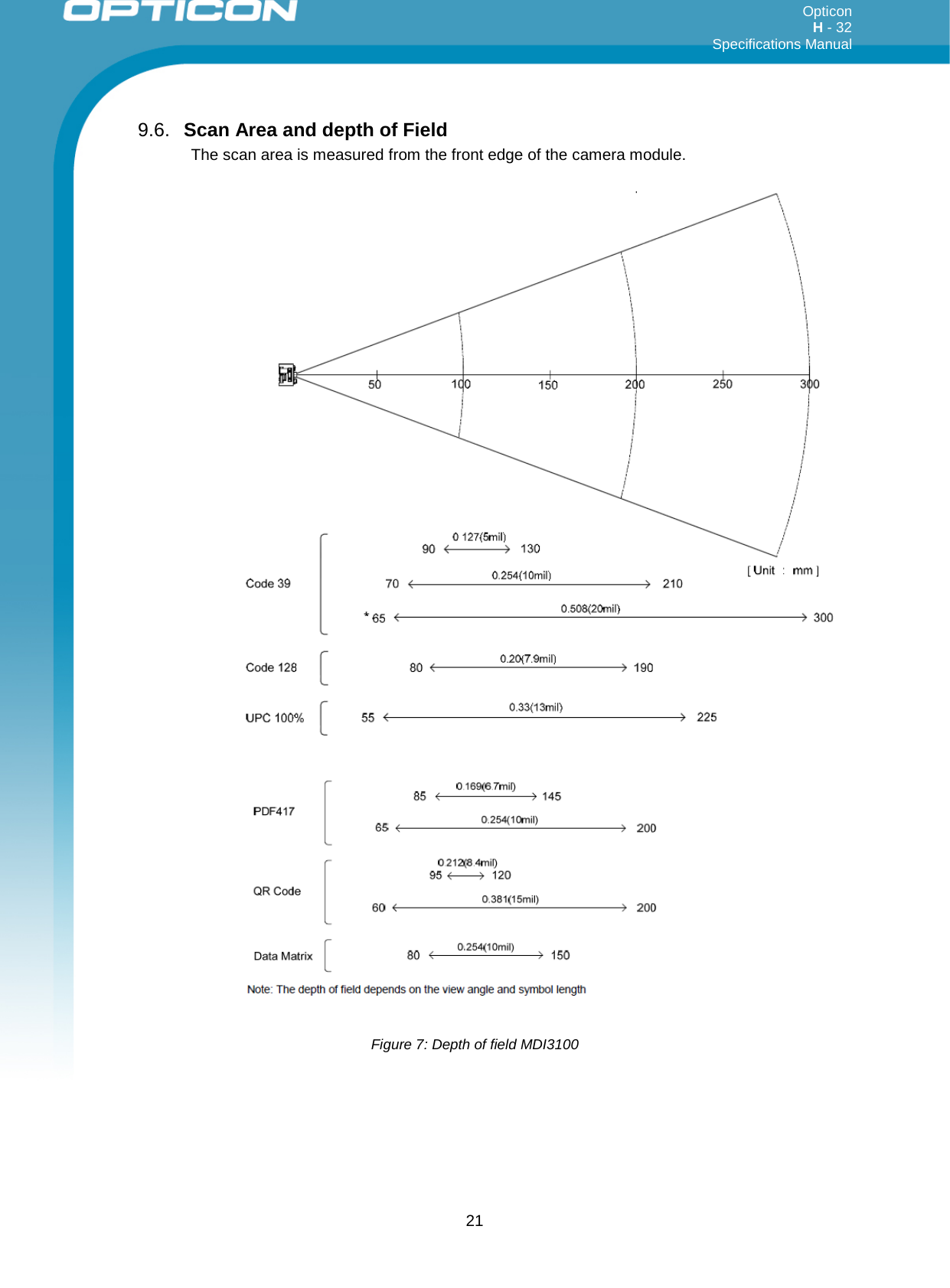
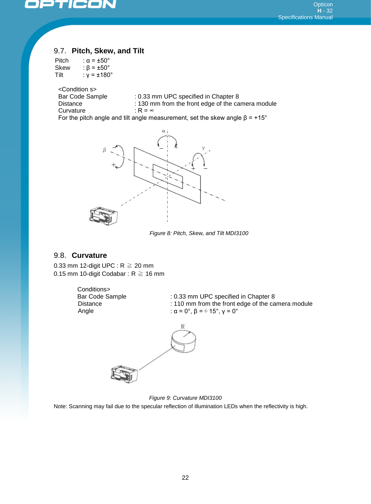
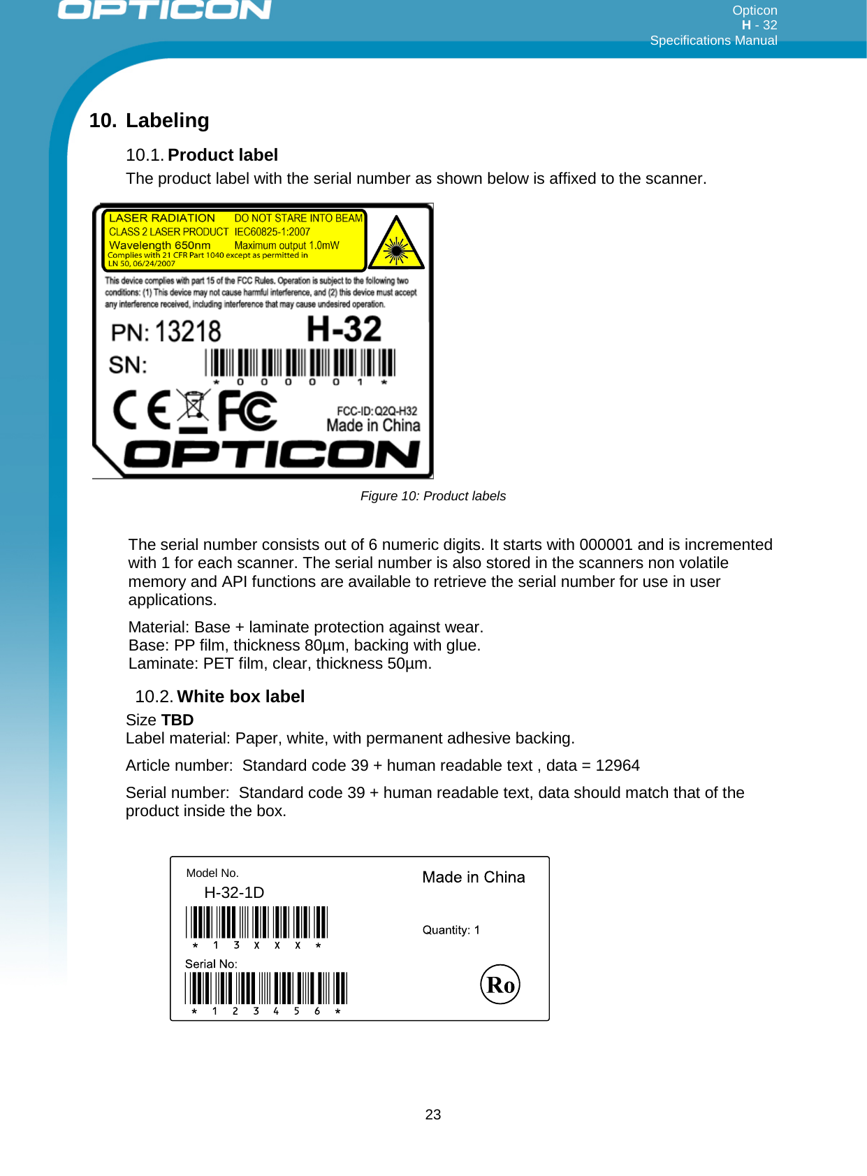
User Manual
Discussion / Help
Navigation