Opticon Sensors Europe H32 H-32 User Manual H19CE Portable Terminal
Opticon Sensors Europe BV H-32 H19CE Portable Terminal
User manual
Portable Terminal
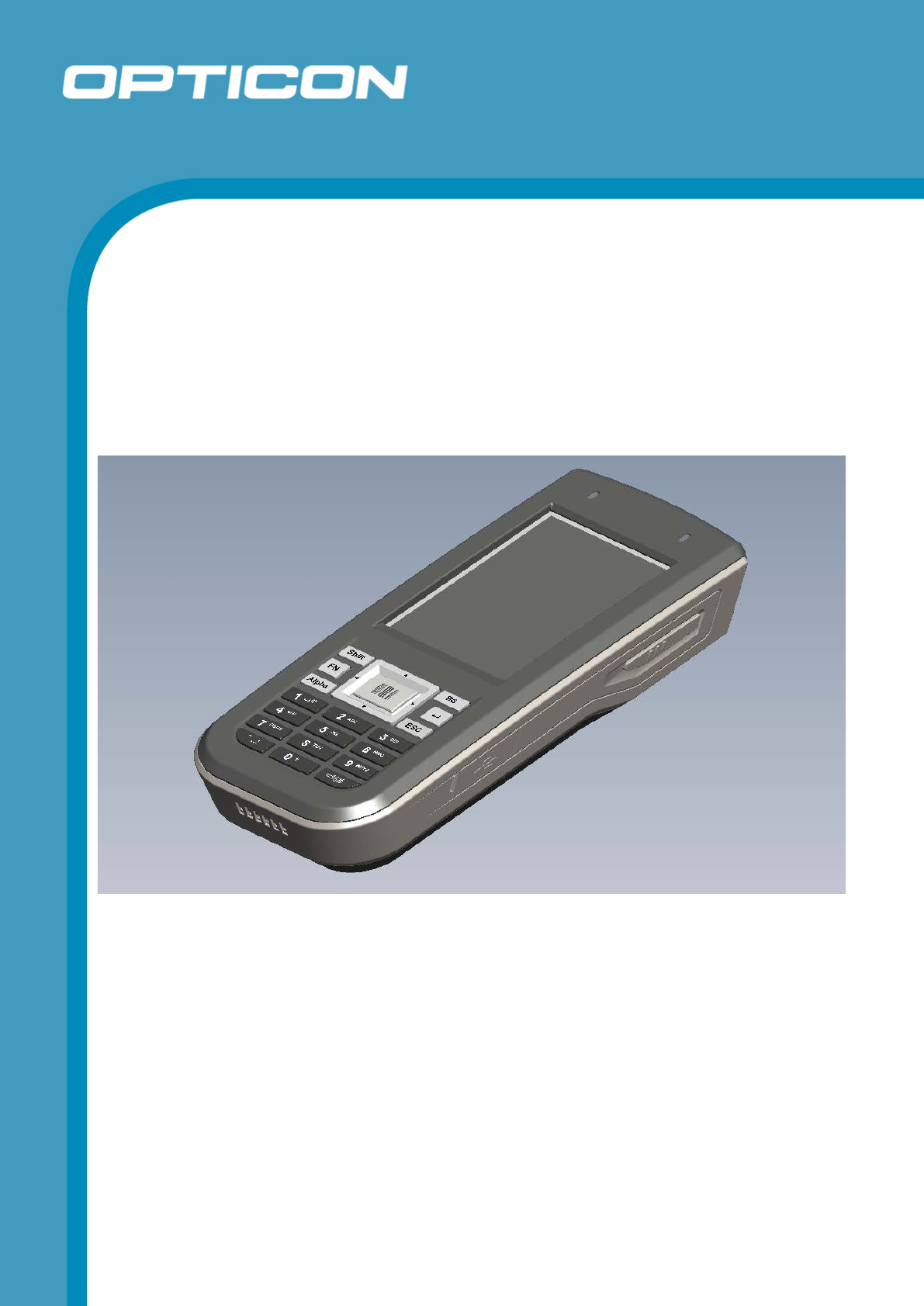
H - 32
The H-32 is a portable Windows CE terminal with a
color display and a built-in laser scan engine (1D or
2D).
Specifications Manual

Opticon
H - 32
Specifications Manual
2
All information subject to change without notice.
Document History
Model Number: H-32 Specification Number:
Edition: 1.08 Original Spec Number:
Date: 2013-10-21
Copyright 2012 Opticon. All rights reserved.
This manual may not, in whole or in part, be copied, photocopied, reproduced, translated or converted to any
electronic or machine readable form without prior written consent of Opticon.
Limited Warranty and Disclaimers
PLEASE READ THIS MANUAL CAREFULLY BEFORE INSTALLING OR USING THE
PRODUCT.
Serial Number
A serial number appears on all Opticon products. This official registration number is directly related to the device
purchased. Do not remove the serial number from your Opticon device. Removing the serial number voids the
warranty.
Warranty
Unless otherwise agreed in a written contract, all Opticon products are warranted against defects in materials and
workmanship for two years after purchase. Opticon will repair or, at its option, replace products that are defective in
materials or workmanship with proper use during the warranty period. Opticon is not liable for damages caused by
modifications made by a customer. In such cases, standard repair charges will apply. If a product is returned under
warranty and no defect is found, standard repair charges will apply. Opticon assumes no liability for any direct, indirect,
consequential or incidental damages arising out of use or inability to use both the hardware and software, even if
Opticon has been informed about the possibility of such damages.
Packaging
The packing materials are recyclable. We recommend that you save all packing material to use should you need to
transport your scanner or send it for service. Damage caused by improper packaging during shipment is not covered
by the warranty.
Trademarks
Trademarks used are the property of their respective owners.
Opticon Inc. and Opticon Sensors Europe B.V. are wholly owned subsidiaries of OPTOELECTRONICS Co., Ltd., 12-
17, Tsukagoshi 4-chome, Warabi-shi, Saitama, Japan 335-0002. TEL +81-(0) 48-446-1183; FAX +81-(0) 48-446-1184
SUPPORT
USA Europe
Phone: 800-636-0090
Email: support@opticonusa.com Email: support@opticon.com
Web: www.opticonusa.com Web: www.opticon.com

Opticon
H - 32
Specifications Manual
3
Contents
1. Abstract ..................................................................................................................................... 5
2. Overview ................................................................................................................................... 5
3. Physical Features ..................................................................................................................... 5
3.1. Dimensions ....................................................................................................................... 5
3.2. Weight ............................................................................................................................... 5
4. Environmental Specifications .................................................................................................. 6
4.1. Operating Temperature and Humidity ................................................................................ 6
4.2. Charging Temperature ...................................................................................................... 6
4.3. Storage Temperature and Humidity ................................................................................... 6
4.4. Ambient Light Immunity ..................................................................................................... 6
4.5. Static Electricity ................................................................................................................. 6
4.6. Drop resistance. ................................................................................................................ 6
4.7. Dust and Drip Proof ............................................................ Error! Bookmark not defined.
5. Controls ..................................................................................................................................... 8
6. Electrical Specifications ......................................................................................................... 10
6.1. Electrical Characteristics (Current measured at 3.7V operating voltage) ......................... 10
6.2. Main Battery .................................................................................................................... 10
6.3. Operating time ................................................................................................................. 10
7. Optical Specifications ............................................................................................................ 11
7.1. Laser Scan Specifications MDL2001 ............................................................................... 11
7.1.1. Tilt of Laser Scan Line ............................................................................................................. 11
7.1.2. Curvature of Scan .................................................................................................................... 11
7.2. Basic Optical Specifications MDI3100 ............................................................................. 12
7.2.1. Aiming pattern .......................................................................................................................... 12
8. Technical Specifications MDL2001........................................................................................ 14
8.1. Print Contrast Signal (PCS) ............................................................................................. 14
8.2. Minimum Resolution ........................................................................................................ 14
8.3. Supported symbologies: .................................................................................................. 14
8.4. Scan Area and Resolution ............................................................................................... 15
8.4.1. Depth of Field ........................................................................................................................... 15
8.5. Pitch, Skew, and Tilt ........................................................................................................ 16
8.6. Curvature ........................................................................................................................ 16
9. Technical Specifications MDI3100 ......................................................................................... 18
9.1. Print Contrast Signal (PCS) ............................................................................................. 18
9.2. Minimum Resolution ........................................................................................................ 18

Opticon
H - 32
Specifications Manual
4
9.3. Wide Bar Code ................................................................................................................ 19
9.4. Motion Tolerance ............................................................................................................. 19
9.5. Barcode Test Sample ...................................................................................................... 20
9.6. Scan Area and depth of Field .......................................................................................... 21
9.7. Pitch, Skew, and Tilt ........................................................................................................ 22
9.8. Curvature ........................................................................................................................ 22
10. Labeling ................................................................................................................................... 23
10.1. Product label ................................................................................................................... 23
10.2. White box label ................................................................................................................ 23
11. Packaging Specifications ....................................................................................................... 24
11.1. Individual Packaging Specification ................................................................................... 24
11.2. Collective Packaging Specification .................................................................................. 25
12. Regulatory Compliance .......................................................................................................... 26
12.1. Laser Safety .................................................................................................................... 26
12.2. EMC ................................................................................................................................ 26
12.3. RoHS .............................................................................................................................. 27
13. Safety ....................................................................................................................................... 28
13.1. Shock .............................................................................................................................. 28
13.2. Temperature Conditions .................................................................................................. 28
13.3. Foreign Materials ............................................................................................................. 28
13.4. Battery ............................................................................................................................. 28
13.5. Other ............................................................................................................................... 28
14. Mechanical Drawing ............................................................................................................... 29
Table of Figures
Figure 1: Scan tilt and curvature ............................................................................................... 11
Figure 2: Aiming Pattern MDI3100 ............................................................................................ 13
Figure 3: Depth of field MDL2001 ............................................................................................. 15
Figure 4: Pitch, skew, and tilt MDL2001 .................................................................................... 16
Figure 5: Curvature MDL2001 .................................................................................................. 17
Figure 6: Motion tolerance MDI3100 ......................................................................................... 19
Figure 7: Depth of field MDI3100 .............................................................................................. 21
Figure 8: Pitch, Skew, and Tilt MDI3100 ................................................................................... 22
Figure 9: Curvature MDI3100 ................................................................................................... 22
Figure 10: Product label ............................................................................................................ 23
Figure 11: Individual packaging ................................................................................................. 24
Figure 12: Collective packaging ................................................................................................ 25
Figure13: Mechanical drawing .................................................................................................. 29

Opticon
H - 32
Specifications Manual
5
1. Abstract
This manual provides specifications for the H-32 portable terminal (hereafter referred to as
“scanner”).
2. Overview
The H-32 is a fully programmable portable Windows CE terminal with a built-in laser scan engine.
Applications can be developed in C++/C# and all other languages supported by Windows CE and
can be installed in the H-32’s internal flash memory. The H-32 also features a Micro SD memory
expansion option on which e.g. a product database can be stored. The H-32’s also features an
easy to use very rugged keyboard for data entry. For data communication, a WiFi (802.11
a/b/g/n/), Bluetooth V 2.1 + EDR and USB active sync interface is added.
An application development kit, required to write, compile and install applications on the H-32 is
available as a free download. This kit has to be used in combination with the standard Microsoft
development tools (Visual Studio). The kit contains libraries for both C++ and .Net for easy access
to the barcode scanner.
3. Physical Features
3.1. Dimensions
W 62.3 x D 25.5 x H 146 mm (TBD)
3.2. Weight
195 g (including battery) (TBD)
Opticon
H - 32
Specifications Manual
6
4. Environmental Specifications
4.1. Operating Temperature and Humidity
Temperature: -10 to 50° C
Humidity: 20% to 80% RH
4.2. Charging Temperature
Temperature: 0 to 40° C
4.3. Storage Temperature and Humidity
Temperature: -20 to 60° C
Humidity: 20% to 90% RH
4.4. Ambient Light Immunity
Decoding performance is guaranteed when the range of illumination on a barcode surface is
between zero and the following values:
Incandescent light 4,000 lx
Fluorescent light 4,000 lx
Sunlight 80,000 lx
Conditions
Barcode Sample: OPTOELECTRONICS Test Sample
PCS = 0.9, Resolution = 0.25 mm, Quiet Zone = 15 mm,
Symbology = 9-digit Code 39, N/W Ratio = 1:2.5
Distance 96 mm from the edge of the scanner
Angle α = 0° β = 15° γ = 0°
Curvature R = ∞
Direct light or specular reflection from a light source should be prevented from entering the
acceptance area.
Note: α, β and γ respectively represent pitch, skew and tilt. Please see section 8 for how
these values are defined.
4.5. Static Electricity
Air discharge: ± 8 kV MAX (No malfunction)
Contact discharge:
± 4 kV MAX (No malfunction)
The criteria minimum performance level (or the permissible performance loss) is specified by the
manufacturer, then either of these may be derived from the product description and documentation,
and by what the user may reasonably expect from the H-32 if used as intended.
Performance criterion A
During and after the test the H-32 shall continue to operate as intended without operator
intervention. No degradation of performance or loss of function is allowed below a minimum
performance level specified by the manufacturer when the H-32 is used as intended. The
performance level may be replaced by a permissible loss of performance. If the minimum
performance level or the permissible performance loss is not specified by the manufacturer,
then either of these may be derived from the product description and documentation, and by

Opticon
H - 32
Specifications Manual
7
what the user may reasonably expect from the H-32 if used as intended.
Performance criterion B
During and after testing, a temporary loss of function is allowed, provided the function is self
recoverable, or can be restored by the operation of the controls or cycling of the power to the H-32 by
the user in accordance with the manufacturer’s instructions.
If performance drop of USB Datalink occurs due to ESD please remove and re insert the USB
connector.
Performance criterion C
During and after testing, Functions, and/or information stored in non-volatile memory, or protected by
a battery backup, shall not be lost.
After testing can be recovered to normal operation by reboot, are permissible by the user in accordance
with the manufacturer’s instructions.
4.6. Drop resistance.
There will be no sign of decreased performance after the following drop test:
Drop the scanner from 1.5 M above the concrete floor (6 sides, 3 times each).
Scratches or discoloration of the casing do not decrease product performance.
Opticon
H - 32
Specifications Manual
8
5. Controls
Items Specifications Remarks
CPU
Type AM3354 ARM Cortex A8
Internal ROM 176K Internal Boot ROM
Internal RAM 64 KB Excluding cache memory
Clock frequency 720 MHz Maximum
Memory
ROM 256 MB NAND Flash
RAM 256 MB Mobile DDR2
SD Card Micro SD card, HC support When booting, max 4GB
LCD
Active area W 43.2 x H 57.6 mm 2.8 Inch
Number of dots W 240 x H 320 QVGA
Color depth 262144
Backlight White LED
Indicators &
Audio
LED Two two-color LED
(red/green) When lit at the same time, red
and green appear as orange
Speaker Mono, 700~20,000 Hz
The speaker is used only for
WM notifications and scan
engine successful scan
confirmation. The speaker is
not intended to be used for
audio playback files such as
MP3.
Vibrating motor Yes
Microphone No
Keyboard
Material Silicone rubber with
protective coating
Side keys Scan button on left side
Scan button on right side
Top key Power button Hold 8 seconds to reset
terminal
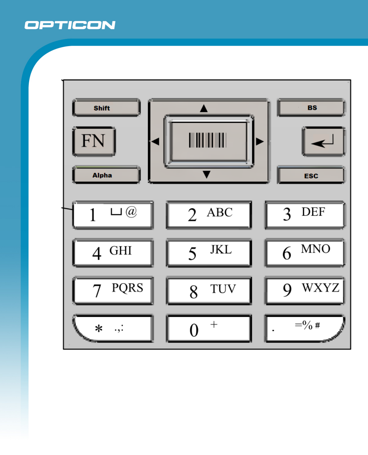
keys
ESC, Fn, Alpha, Shift,
Backspace (BS), Enter, 4 way
navigation, scan, 10 numeric
keys, * and a # key.
See 5.1 Keyboard
Clock Built-in RTC
YY/MM/DD/HH/MM/SS
(Leap-year supported)
Accurate within 90 seconds
per month
Battery backed up
Communications
WiFi 802.11 a/b/g/n Summit, SD-SSD40NBT.
2.4GHz only
Bluetooth 2.1 + EDR Summit, SD-SSD40NBT
USB 2.0 Micro USB OTG
Opticon
H - 32
Specifications Manual
9
5.1. Keyboard
Opticon
H - 32
Specifications Manual
10
6. Electrical Specifications
6.1. Electrical Characteristics (Current measured at 3.7V operating voltage)
Parameter Typ Unit Remarks
Operating voltage 3.4–4.2 V Lithium-ion battery
Operating current 300 mA Backlight on, WLAN
connected, 1 scan/minute
Stand-by current <200 mA Not scanning, WiFi off,
backlight on.
Sleep current <4 mA When the power is OFF
6.2. Main Battery
The main battery is a lithium-ion battery:
• Nominal capacity: 1800 mAh (NP120)
• Nominal voltage: 3.7 V.
• Low voltage: Less than 3.4 V
• Usable time: Approx 4 hours.
• Data hold time (clock and SRAM): 2 hours
The backup battery is an 15 mAh secondary battery.
6.3. Operating time
Parameter Typ Unit Remarks
Operating time 4 Hours Backlight on, WLAN
connected, 1 scan/minute
Stand-by time 6 Hours Not scanning, WiFi off,
backlight on.
Off time 11 Days When the power is OFF
Opticon
H - 32
Specifications Manual
11
7. Optical Specifications
7.1. Laser Scan Specifications MDL2001
Parameter Specification Unit
Light-emitting element Red laser diode -
Emission wavelength
650 ±10 (25° C)
nm
Light output Light output 1.0 or less mW
Scanning method
Bi-directional scanning
-
Scanning speed 100 ±20 scans/s
Scan angle ° Scan angle: 54 ±5 °
Read angle: 44 (Min) °
Notes:
Refer to chapter 8, “Technical Specifications,” to read about scanning performance.
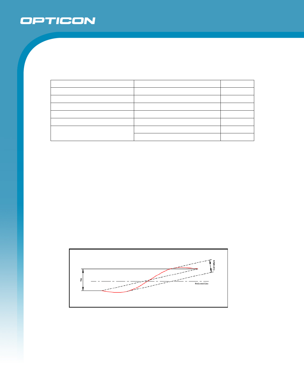
7.1.1. Tilt of Laser Scan Line
Maximum tilt between both ends of laser scan line Less than 0.92° upward tilt from
the scan origin. Maximum of 2.46 mm when measured at the point 150 mm away
from the scan origin. (Measurement was done from the center of the scan line.)
7.1.2. Curvature of Scan
Maximum gap between the straight line connecting both ends of the laser scan line
and the actual laser scan line. Less than 1.17° curvature from the scan origin (from a
mirror motor mirror). Maximum of 3.06 mm when measured at the point 150 mm
away from scan origin. (Measurement was done from the center of the scan line.)
Figure 1: Scan tilt and curvature
Opticon
H - 32
Specifications Manual
12
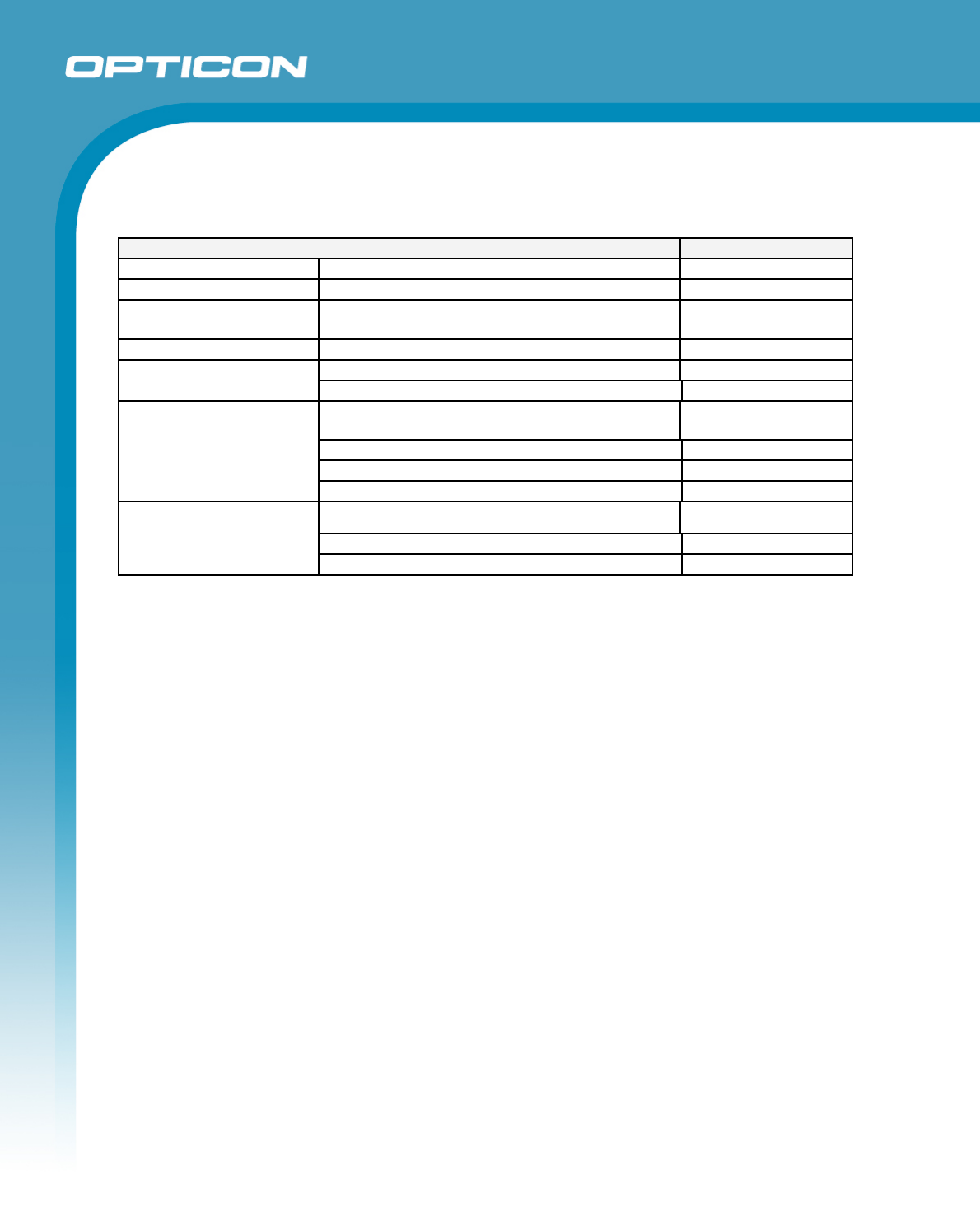
7.2. Basic Optical Specifications MDI3100
Item
Characteristics
Scan method
CMOS area sensor (black and white)
-
Number of effective pixel
(H) × (V)
752 × 480 dot
Image capture speed
(*1)
Frame rate
60 fps
Focal distance
From the front edge of scan engine
130 mm
View angle
Horizontal
Approx. 40.6°
Vertical
Approx. 26.4°
Auxiliary light source
( LED × 2 )
Red LED -
Peak Wave Length
617 nm
Directivity angle 2θ1/2 (*2)
60°
Maximum radiation output (*3)
15000 mcd
Light source for aiming
( LED x 1)
Green LED
-
Peak Wave Length
528 nm
Maximum radiation output (*4)
18700 mcd
*1 The fastest seed of image capture
*2 The reference value extracted from the LED datasheet
*3 *4 The reference value extracted from the datasheet (conditions: 25 °C, IF = 140 mA)
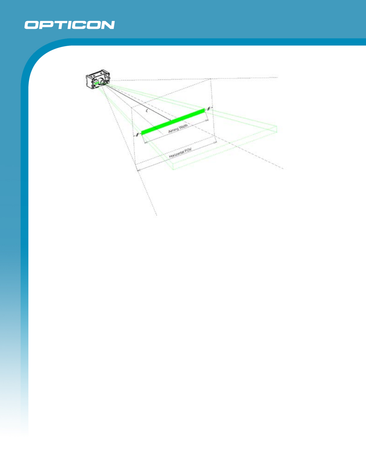
7.2.1. Aiming pattern
The aiming is used for the following purpose:
1. Fill light to recognize the appropriate reading range.
2. Fill light when auto trigger is used.
The aiming specifications are as follows:
- An optical axis of imaging field of view and the center of horizontal aiming width
coincide at a distance of L=110±20 mm from the front edge of the camera module.
- The aiming horizontal width to the horizontal width of imaging filed of view at a
distance of L=110 is 80%±10%.

Opticon
H - 32
Specifications Manual
14
8. Technical Specifications MDL2001
The conditions are as follows, unless otherwise specified.
Conditions
Ambient temperature
and humidity: Room temperature (5 to 35º C)
Room humidity (45% to 85% RH)
Ambient light: 500 to 900 lx
Background:
Power supply voltage
Barcode = black
Space = white
Margin = white
Background of label = black
3.3 V
Decoding test: Approve the performance when decoding is successful in all ten tests.
(Decoding is deemed successful when completed in 0.5 seconds or less.)
8.1. Print Contrast Signal (PCS)
PCS=0.45 or higher (over 70% of reflectivity of space and quiet zone).
Scanning performance may decline if dirt or scratches mark the optical window. Keep the
optical window clean.
8.2. Minimum Resolution
0.127 mm
8.3. Supported symbologies:
Linear (1D)
JAN/UPC/EAN, incl. add-on S-Code
Codabar/NW-7 Telepen
Code 11 Tri-Optic
Code 39 UK/Plessey
Code 93
Code 128 Postal codes (1D)
GS1-128 (EAN-128) Chinese Post
GS1 Databar (RSS) Korean Postal Authority Code
IATA
Industrial 2of5 2D codes
Interleaved 2of5 GS1 Composite Codes
ISBN-ISMN-ISSN MicroPDF417
Matrix 2of5 PDF417
MSI/Plessey
Opticon
H - 32
Specifications Manual
15
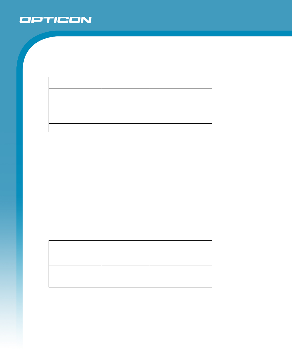
8.4. Scan Area and Resolution
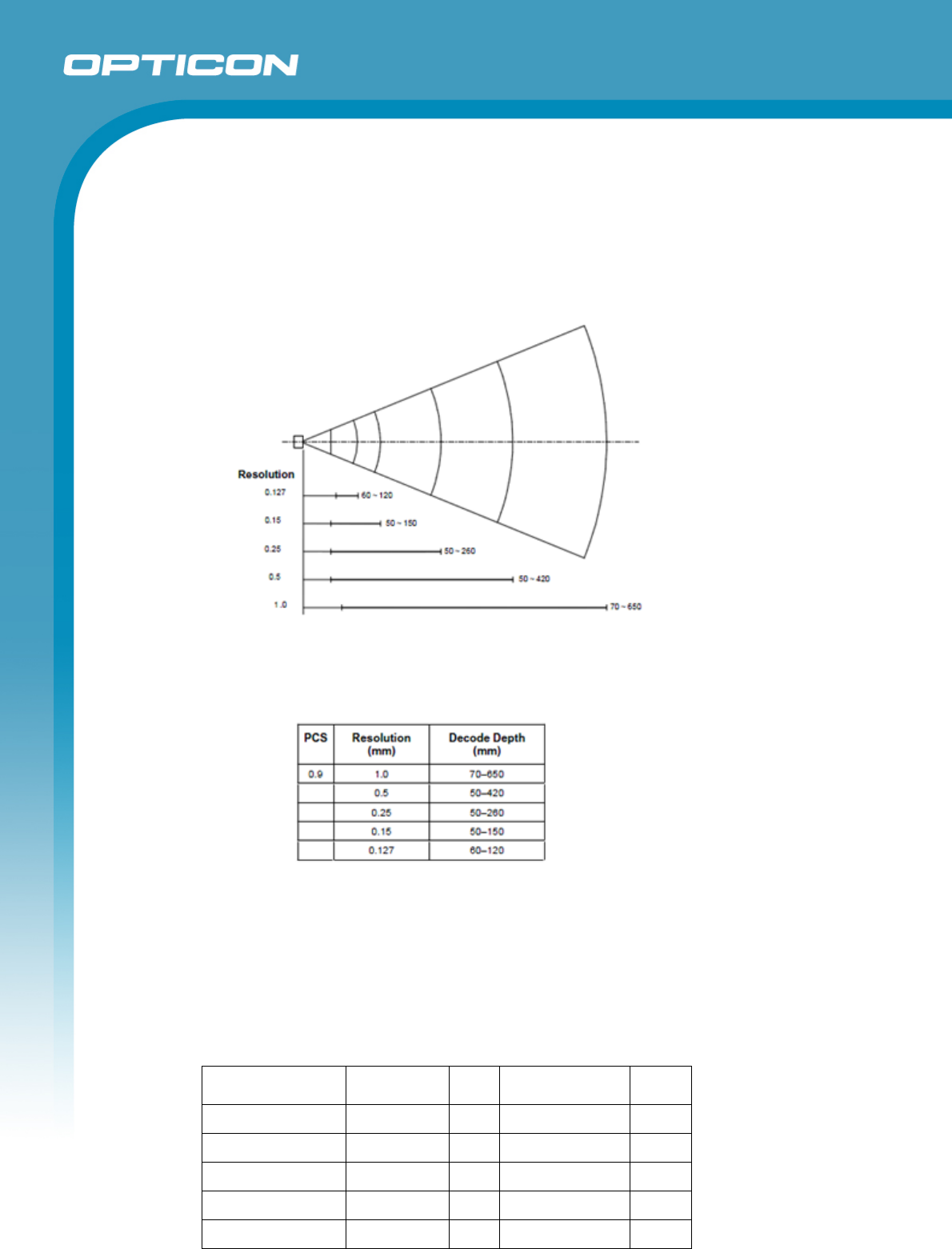
8.4.1. Depth of Field
The depth of field is measured from the edge of the scanner. The scanning range is
within the circular arc centered on the scan origin.
Figure 3: Depth of field MDL2001
Conditions
Barcode Sample: OPTOELECTRONICS Test Sample
N/W Ratio: 1:2.5
Angle: α = 0°, β = 15°, γ = 0°
Curvature: R = ∞
Resolution (mm) Symbology PCS Quiet Zone Digits
1.0 Code 39 0.9 25 mm 1
0.5 Code 39 0.9 18 mm 3
0.25 Code 39 0.9 10 mm 8
0.15 Code 39 0.9 7 mm 10
0.127 Code 39 0.9 5 mm 4
Opticon
H - 32
Specifications Manual
16
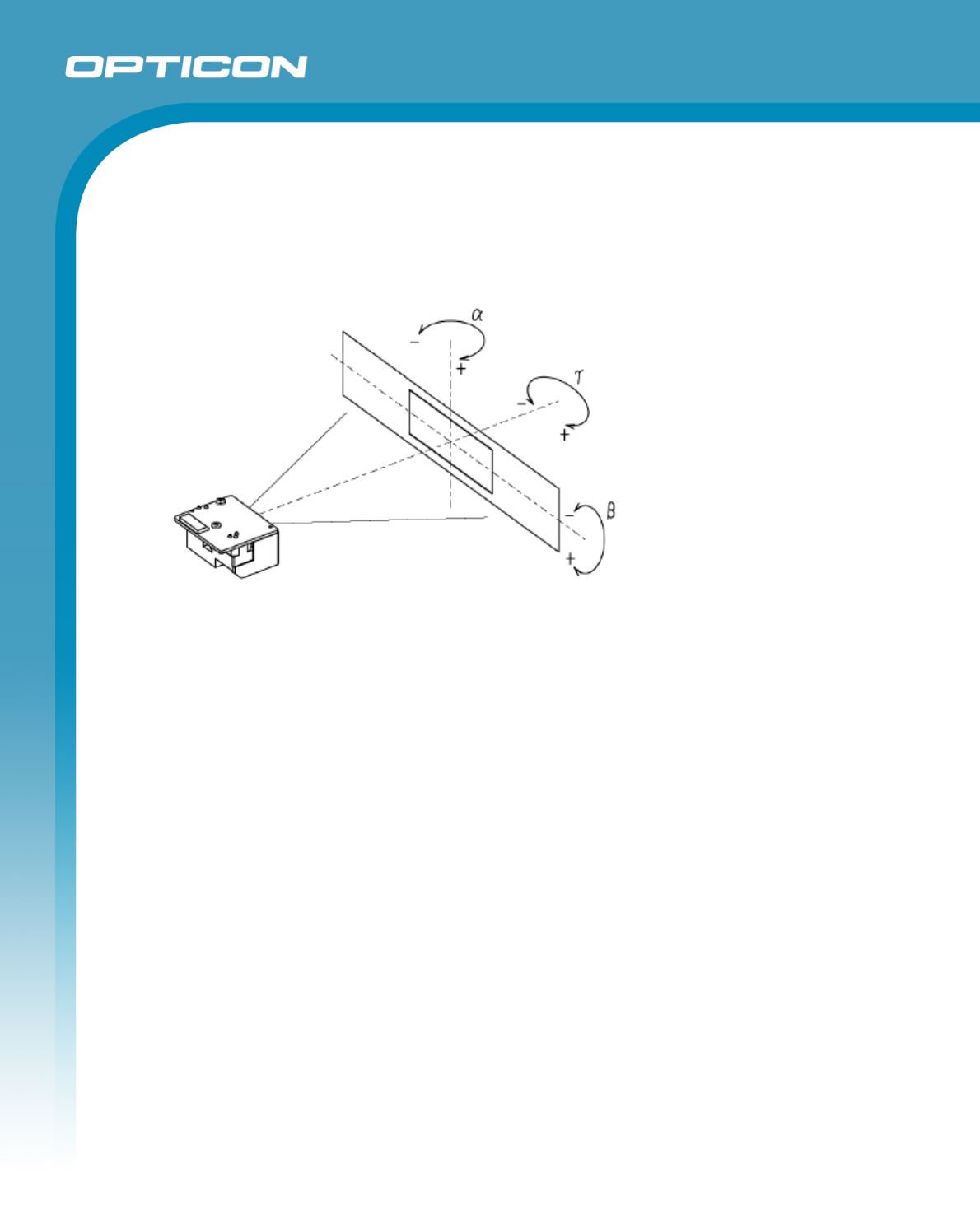
8.5. Pitch, Skew, and Tilt
Pitch angle: α = ±35°
Skew angle: β = ±50° (Excluding dead zone)
Dead zone: β = ±8° (There are some areas in which decoding fails due to specular reflection)
Tilt Angle: γ = ±20°
Figure 4: Pitch, skew, and tilt MDL2001
Conditions
Barcode Sample: OPTOELECTRONICS Test Sample
Distance 110 mm from the exit window
Label Pitch, Skew Angle, Dead Zone
PCS = 0.9, Resolution = 0.25 mm, Symbology = 9-digit Code 39,
Quiet Zone = 10 mm, N/W Ratio = 1:2.5
Tilt Angle
PCS = 0.9, Resolution = 0.26 mm, Symbology = 13-digit JAN, Quiet Zone = 10
mm
Angle Curvature: R = ∞, Skew Angle = β +15° (for measuring Pitch Angle and Tilt
Angle)
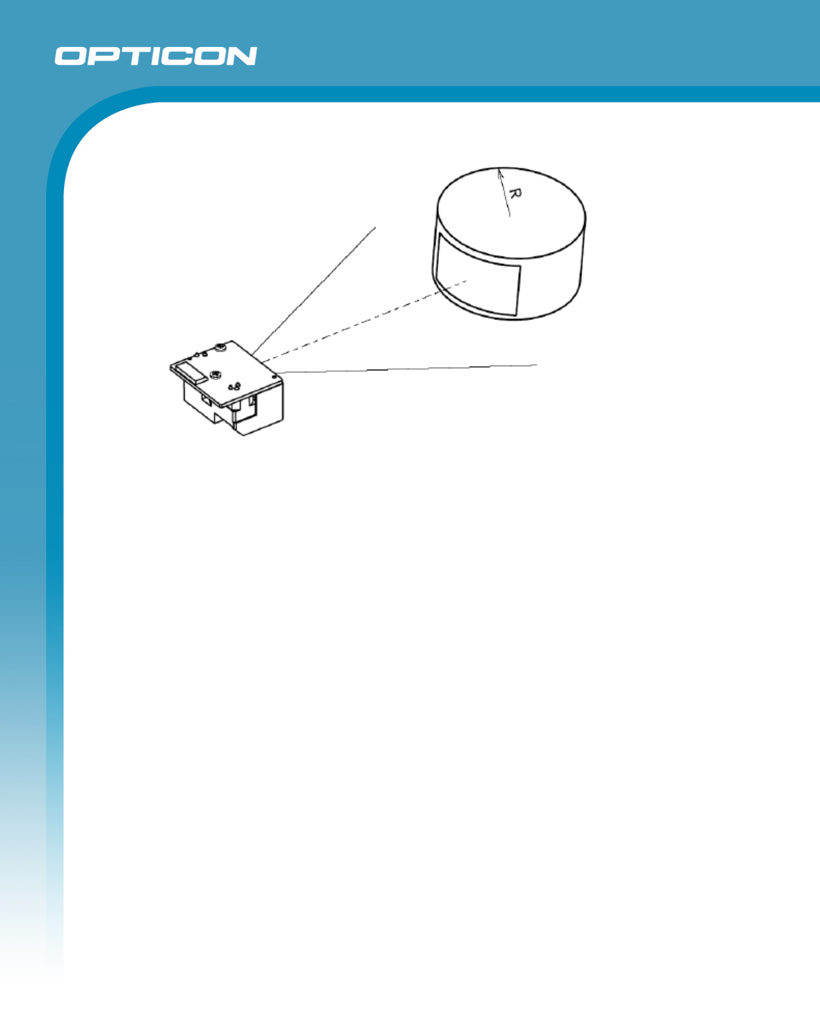
8.6. Curvature
With 8-digit JAN/UPC/EAN barcodes, decoding performance is guaranteed when
R≥15 mm.
With 13-digit JAN/UPC/EAN barcodes, decoding performance is guaranteed when
R≥20 mm.
Opticon
H - 32
Specifications Manual
17
Figure 5: Curvature MDL2001
Conditions
Barcode Sample: OPTOELECTRONICS Test Sample
PCS = 0.9, Resolution = 0.26 mm, Quiet Zone = 10 mm
Distance 110 mm from the edge of the exit window
Angle Skew Angle β = +15°
Opticon
H - 32
Specifications Manual
18
9. Technical Specifications MDI3100
Emit aiming light of the MDI-3100-SR to the center of a bar code for scanning. The conditions for technical
specifications are as follows, unless otherwise specified in each section.
<Conditions>
Ambient Temperature and Humidity
: Room temperature and room humidity
Ambient Light
: 100 ~200 lux (on the surface of a bar code)
Pitch Angle
: α= 0°
Skew Angle
: β = 15°
Tilt Angle
: γ = 0°
Curvature
: R = ∞
Power Supply Voltage
: 3.3 and 5.0 V
PCS (1D and 2D)
: 0.9 or higher
Scanning Test
: Accept the performance with 90% or more
success rate for 10 tries of scan. One
scan should be tested within 2 seconds
Bar Code Test Sample (1D and 2D)
: Specified below
< Test chart >
For 1D codes, OPTOELECTRONICS test samples
For GS1 Databar, stacked codes and 2D codes, printed by a dedicated printer for bar code
9.1. Print Contrast Signal (PCS)
PSC 0.3 or higher
<Conditions>
MRD
: 32% and higher
(70% or higher reflectivity of space and
quiet zone)
Distance 130 mm from the front edge of the
camera module
Bar Code Sample
: UPC specified in Chapter 8.
(Resolution: 0.33 mm, PCS: 0.3)
PCS = Reflectance of white bar-Reflectance of black bar
Reflectance of white bar
9.2. Minimum Resolution
1D Code : 0.127 mm (5 mil) Code 39 specified in Chapter 8
GS1-Databar : 0.169 mm (6.7 mil) GS1 Databar-Limited specified in Chapter 8
Stacked Code : 0.169 mm (6.7 mil) PDF417, GS1 Databar-Limited Composite specified in Chapter 8
2D Code : 0.212 mm (8.4 mil) OR Code and Data Matrix specified in Chapter 8
Opticon
H - 32
Specifications Manual
19
<Conditions>
Bar Code Sample
: The above codes specified in Chapter 8
Distance
: 100 mm from the front edge of the camera module
Angle
: α = 0°, β =+15°, γ = 0°
Curvature
: R = ∞
For the pitch angle and tilt angle measurement, set the skew angle β = +15°
9.3. Wide Bar Code
Code 39 with width of 100 mm and resolution of 0.2 mm can be read.
Conditions>
Bar Code Sample
: 0.20 mm Code 39 specified in
Chapter 8
Distance : 160 mm from the front edge of the
camera module
Angle
: α = 0°, β =
+
15°, γ = 0°
Curvature
: R = ∞
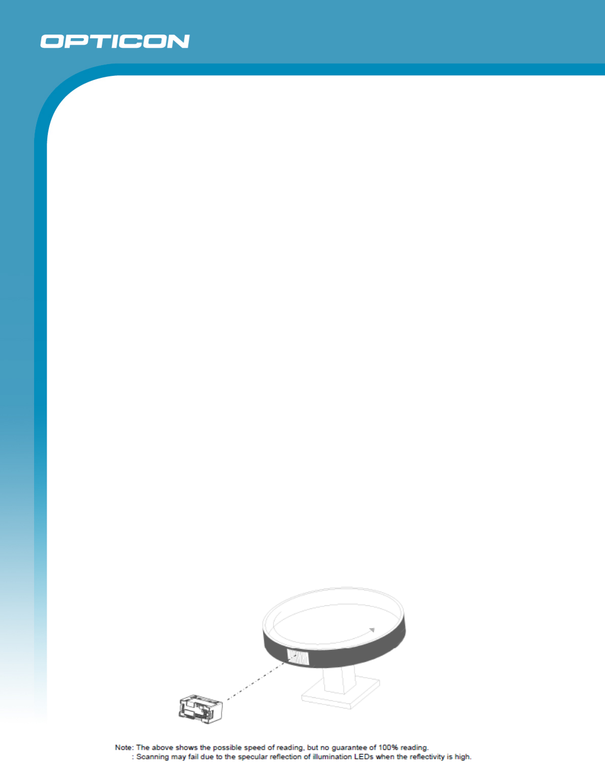
9.4. Motion Tolerance
UPC bar code 100% can be read when it is moving at 2m/s.
<Conditions>
Ambient Temperature and Humidity
: Room temperature and Room humidity
Ambient Light
: 500 lux to 1000 lux (on the surface of a bar code)
Distance
: 130 mm from the front edge of the camera module
Angles
: α= 0°
Skew
: β = 15°
Tilt
: γ = 0°
Curvature
: R = ∞
Power Supply Voltage
: 3.3 and 5.0 V
PCS (1D and 2D)
: 0.9 or higher
Bar Code Sample
: UPC with 0.33 mm resolution specified in Chapter
8
Figure 6: Motion tolerance MDI3100
Opticon
H - 32
Specifications Manual
20
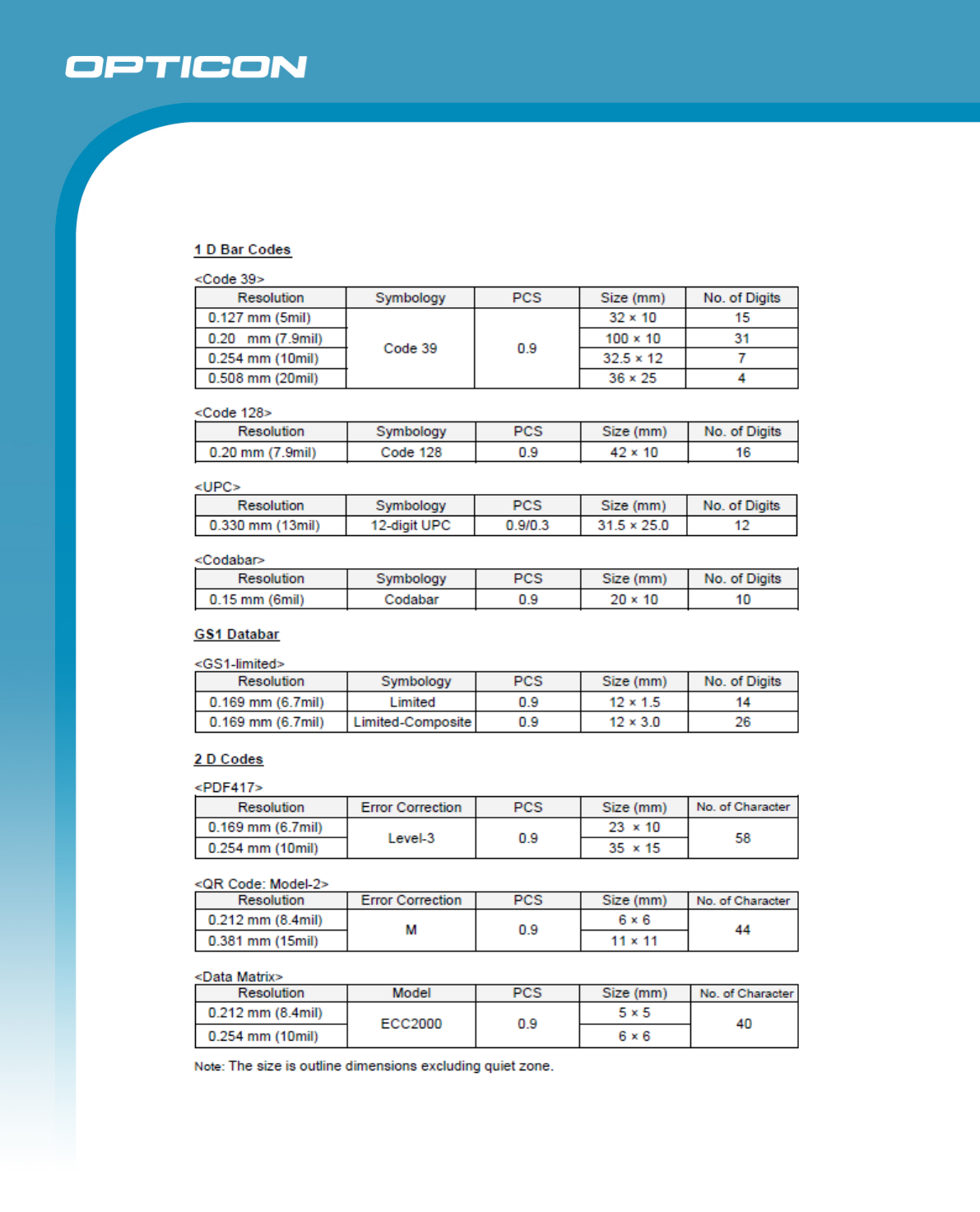
9.5. Barcode Test Sample
Opticon
H - 32
Specifications Manual
21
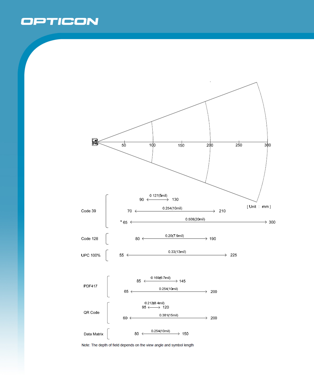
9.6. Scan Area and depth of Field
The scan area is measured from the front edge of the camera module.
Figure 7: Depth of field MDI3100
Opticon
H - 32
Specifications Manual
22
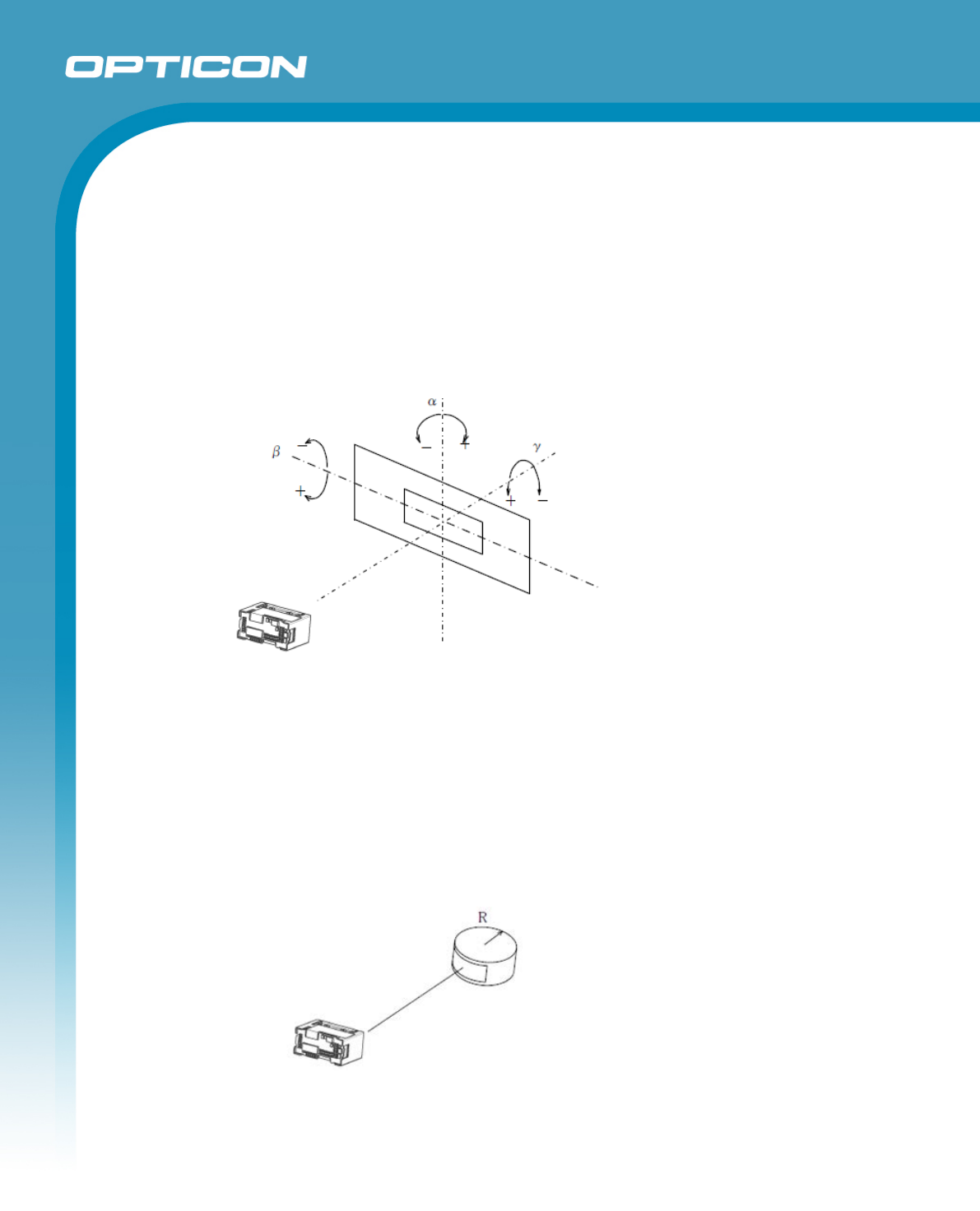
9.7. Pitch, Skew, and Tilt
Pitch : α = ±50°
Skew : β = ±50°
Tilt : γ = ±180°
<Condition s>
Bar Code Sample
: 0.33 mm UPC specified in Chapter 8
Distance
: 130 mm from the front edge of the camera module
Curvature
: R = ∞
For the pitch angle and tilt angle measurement, set the skew angle β = +15°
Figure 8: Pitch, Skew, and Tilt MDI3100
9.8. Curvature
0.33 mm 12-digit UPC : R ≧ 20 mm
0.15 mm 10-digit Codabar : R ≧ 16 mm
Conditions>
Bar Code Sample
: 0.33 mm UPC specified in Chapter 8
Distance
: 110 mm from the front edge of the camera module
Angle : α = 0°, β =+15°, γ = 0°
Figure 9: Curvature MDI3100
Note: Scanning may fail due to the specular reflection of illumination LEDs when the reflectivity is high.
Opticon
H - 32
Specifications Manual
23
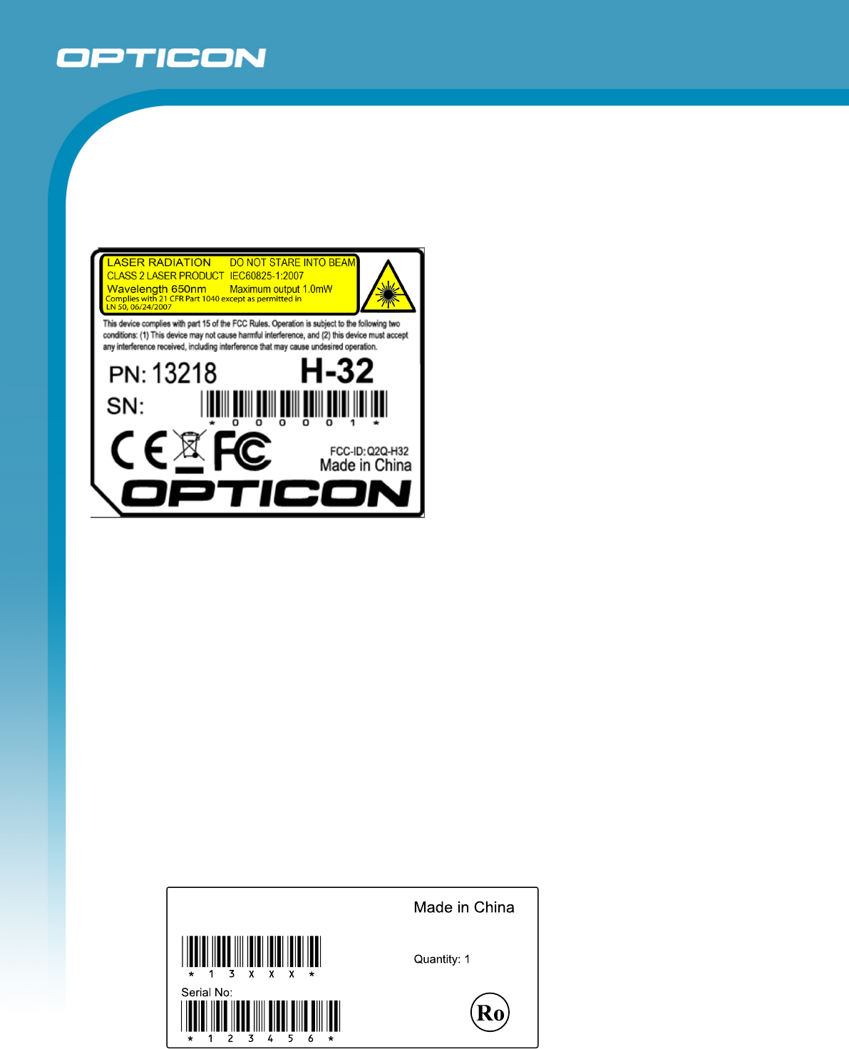
10. Labeling
10.1. Product label
The product label with the serial number as shown below is affixed to the scanner.
Figure 10: Product labels
The serial number consists out of 6 numeric digits. It starts with 000001 and is incremented
with 1 for each scanner. The serial number is also stored in the scanners non volatile
memory and API functions are available to retrieve the serial number for use in user
applications.
Material: Base + laminate protection against wear.
Base: PP film, thickness 80µm, backing with glue.
Laminate: PET film, clear, thickness 50µm.
10.2. White box label
Size TBD
Label material: Paper, white, with permanent adhesive backing.
Article number: Standard code 39 + human readable text , data = 12964
Serial number: Standard code 39 + human readable text, data should match that of the
product inside the box.
Model No.
H-32-1D

Opticon
H - 32
Specifications Manual
24
11. Packaging Specifications
11.1. Individual Packaging Specification
TBD
Figure 11: Individual packaging

Opticon
H - 32
Specifications Manual
25
11.2. Collective Packaging Specification
TBD
Figure 12: Collective packaging
Note: The “RO” mark labeled on the package tray or package box guarantees that the
applicable product has passed our test of RoHS restrictions compliance (the
restriction of the use of certain hazardous substances in electrical and electronic
equipment, 2002/95 EC). However, this document does not have any legal weight in
the European Union.

Opticon
H - 32
Specifications Manual
26
12. Regulatory Compliance
12.1. Laser Safety (1D model)
IEC 60825-1:2007 Laser Class 2
CDRH Laser Class 2
FDA CDRH Laser class II. Complies with 21 CFR 1040.10 and 1040.11 except for
deviations pursuant to laser notice No. 50 dated June 24, 2007.
Class II laser devices are not considered to be hazardous when used for their
intended purpose. Avoid staring into the laser beam.
12.2. EMC
EN55022
EN55024
Federal Communications Commission (FCC) Statement
15.21
You are cautioned that changes or modifications not expressly approved by the part
responsible for compliance could void the user’s authority to operate the equipment.
15.105(b)
This equipment has been tested and found to comply with the limits for a Class B digital
device, pursuant to part 15 of the FCC rules. These limits are designed to provide reasonable
protection against harmful interference in a residential installation.
This equipment generates uses and can radiate radio frequency energy and, if not installed
and used in accordance with the instructions, may cause harmful interference to radio
communications. However, there is no guarantee that interference will not occur in a particular
installation. If this equipment does cause harmful interference to radio or television reception,
which can be determined by turning the equipment off and on, the user is encouraged to try to
correct the interference by one or more of the following measures:
-Reorient or relocate the receiving antenna.
-Increase the separation between the equipment and receiver.
-Connect the equipment into an outlet on a circuit different from that to which the receiver is
connected.
-Consult the dealer or an experienced radio/TV technician for help.
This device complies with part 15 of the FCC Rules. Operation is subject to the following two
conditions:
1) this device may not cause interference and
2) this device must accept any interference, including interference that may cause undesired
operation of the device.

Opticon
H - 32
Specifications Manual
27
FCC RF Radiation Exposure Statement:
For body worn operation, this phone has been tested and meets FCC RF exposure
guidelines when used with an accessory that contains no metal and that positions the
handset a minimum of 5.0mm from the body. Use of other accessories may not
ensure compliance with FCC RF exposure guidelines.
12.3. RoHS
RoHS: The restriction of the use of certain hazardous substances in electrical and
electronic equipment, 2002/95 EC.
Opticon
H - 32
Specifications Manual
28
13. Safety
Handle this product carefully. Do not deliberately subject it to any of the following.
13.1. Shock
Do not throw or drop the scanner.
Do not place heavy objects on the scanner.
13.2. Temperature Conditions
Do not use the scanner at temperatures outside the specified range.
Do not pour boiling water on the scanner.
Do not throw the scanner into the fire.
Do not leave the scanner on the dashboard of a car.
13.3. Foreign Materials
Do not immerse the scanner in liquids.
Do not subject the scanner to chemicals.
13.4. Battery
Do not overcharge nor over discharge the battery.
Do not charge the battery at freezing temperatures.
Do not charge the battery at very high temperatures.
When the scanner is not used for a very long time, remove the battery from the
battery compartment.
Replace the battery when its lifetime has expired. This is after two years of operation
or 500 charge/discharge cycles. (When a half discharged battery is recharged, this
counts as only half a cycle.)
13.5. WiFi 5GHz
Operations in 5150-5250 MHz band is for indoor use only.
13.5. Other
Do not disassemble this product.
The scanner may be damaged by high voltage discharges.

Opticon
H - 32
Specifications Manual
29
14. Mechanical Drawing
TBD
Figure13: Mechanical drawing