Orolia MT-1 McMurdo/Transas MT-1 User Manual Installation Manual 89 041N
Orolia Ltd McMurdo/Transas MT-1 Installation Manual 89 041N
Orolia >
Contents
- 1. Installation Manual 89 041N
- 2. Operating Manual Section 1
- 3. Operation Manual Section 2
- 4. Operation Manual Section 3
Installation Manual 89 041N
Installation Manual
UAIS Transponder System
S4-6 89-041 Section 4 Issue 5
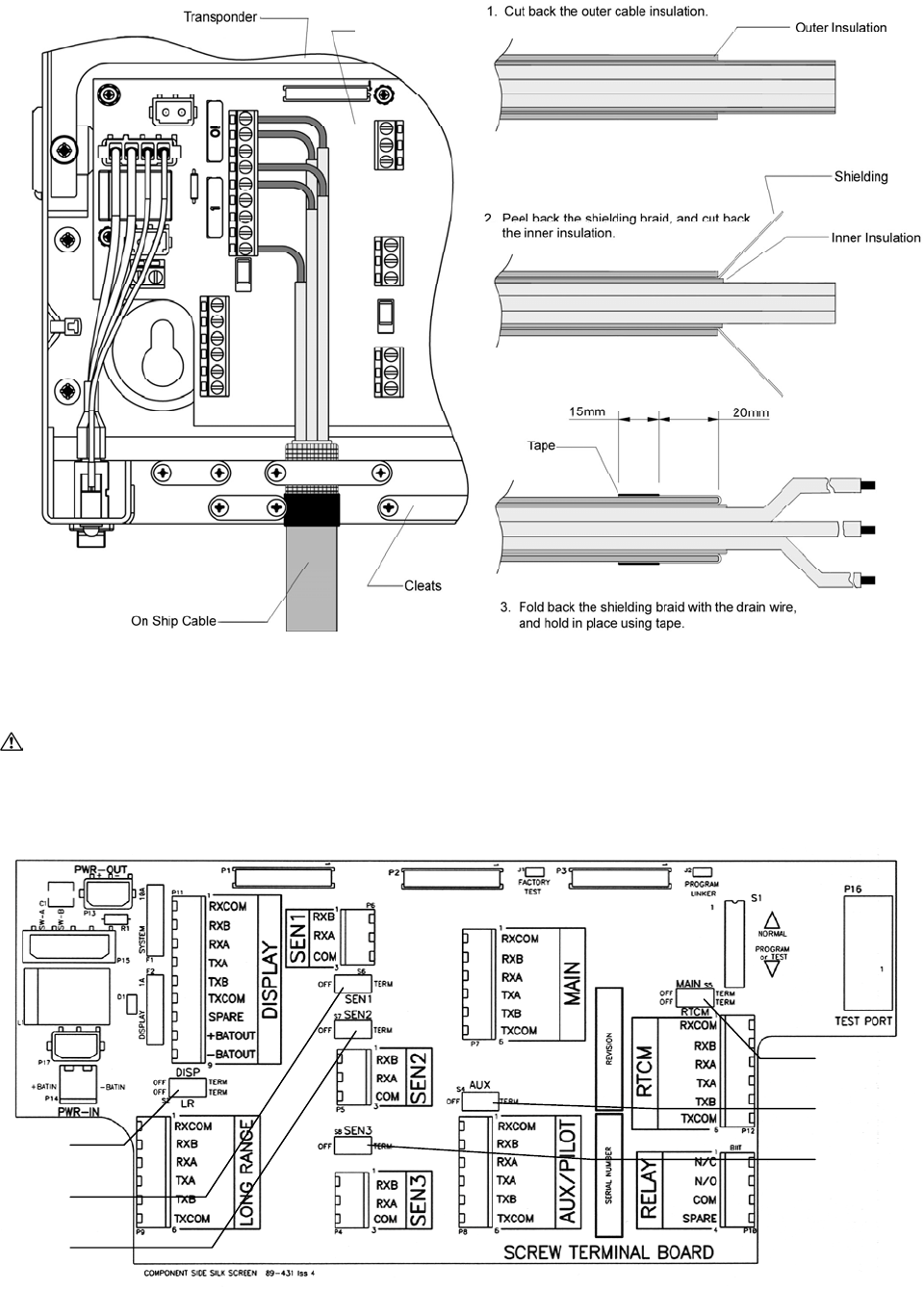
Method of connecting screens at the transponder
Test and program connections
WARNING: Do not interfere with switch S1 or the links “Factory Test” and “Program Linker”.
These are specialised functions for use by factory technicians only. For the same reason, make
no connection to Test Port.
Screw Terminal
Board
S5
S4
S8
S2
S6
S7
89-041 Section 4 Issue 5 S4-7
Power supply
Connected to the ship’s 24V DC emergency power source through a 2-pole switched fused
supply to allow isolation for servicing. The power requirements are 24V DC +30% -10%, 3.5A
maximum.
Standby power requirement 21 W; 0.9 Amp at 24V DC
Peak power requirement 75 W; 3.5 Amp at 24V DC
Required conductor area as a function of cable length
Power cable length Required conductor area
0 – 10 metres 0.75 mm2
10 – 20 metres 1.5 mm2
20 – 40 metres 3.0 mm2
Isolation between the power supply connections and any other connection to the transponder is
1kV minimum.
The DC power source should comply with IMO guidelines for the class of vessel concerned.
National authorities and classification societies may have their own power supply requirements
that should also be considered.
If the available supply is AC, a converter, P/N 89-029, is available as an option.
DISP port - Display VDU
The DISP port connects the VDU Display unit with the Transponder. This port is vital to the
functionality of the transponder and the VDU and must be connected. To prevent any
malfunction of this port it is not possible to change the configuration.
Display cable:
Four twisted pairs, screened, PVC sheathed.
Cable length to display Required conductor area
0 – 100 metres 0.8 mm2 each wire
100 metres + 1.5 mm2 each wire
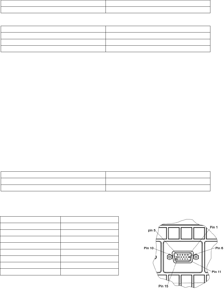
The connection between the Screw terminal board and the VDU unit is given below, showing
the rear of the VDU and the 15-pin connector, and the pin identification of the connector.
Transponder VDU pin
Rx common 2
Rx B 1
Rx A 6
Tx A 12
Tx B 13
Tx common 8
+ Bat out 3
- Bat out 4
The twisted pairs are assigned as (Rx A/B), (Tx A/B),
(common pair) and (battery pair)
The DISPLAY port can be connected to a Personal Computer, but two precautions are
necessary: special software is required to display the received information, and usually it is
necessary to convert the RS 422 signal from the transponder to a RS-232 signal in order to
interface to the PC.

S4-8 89-041 Section 4 Issue 5
SEN 1, 2, 3 ports - Sensors
The Sensor input port can be configured to receive data from the Gyro, the GNSS used for
navigation and the LOG. Each of the three sensor (SEN1, SEN2 and SEN3) ports can be
independently configured to receive information from one of these sensors. Alternatively ALL
sensor information can be received via ONE of the sensor ports.
The sensor ports require configuration before use; this is described in the Operation Manual.
The AIS must be connected to:
• The GNSS unit used for navigation
• The gyrocompass providing heading information
If available the following information can be connected to the AIS:
• Rate-Of-Turn (ROT)
• Speed over ground from Bottom referenced log
Recommended cable for connection of Sensors:
Single twisted pair, shielded, PVC sheathed.
Cable length to display Required dimension
0 – 100 metres 0.8 mm2 each wire
Sensor wire connection
The twisted pair shall be assigned as RxA and RxB
SEN Ports necessary sentences:
The basic requirements are:
IEC 61162-2 standard
ITU-T V.11 electrical properties
Speed can be configured from 1200 - 38400 bits/sec
Data bits 8, Stop bits 1, Parity none
All required as well as optional sentences are listed in the table; ensure that the connected
sensor transmits at least the required sentences (as given by IEC 61162):
IEC 61162-2 sentence format
Sensor Data Required Optional
Reference datum DTM
Positioning system
Time of position
Latitude/longitude
Position accuracy
GNS, GLL GGA, RMC
Speed over ground
(SOG) VBW VTG, OSD, RMC
Course over ground
(COG) RMC VTG, OSD
RAIM indicator GBS
GNSS
Route plan RTE, WPL
Heading HDT OSDGYRO Rate of turn (ROT) ROT
LOG Speed over ground
(SOG) VBW
89-041 Section 4 Issue 5 S4-9
Course over ground
(COG)
Main and AUX high speed input/output ports
The Transponder has two high-speed communication ports. The ports are identical, the same
information is input and output on these ports. All information received and transmitted on the
VHF link will be reflected as correct IEC 61162 sentences. All error messages will also be
transmitted.
The Main port will primarily be used to connect external equipment such as ECDIS and ARPA
or another navigation information display system.
The AUX port will primarily be used for connection to the “pilot plug” - a connector installed on
the bridge near the pilot operation position so that the pilot can connect a Personal Pilot Unit,
which is normally a laptop computer with the pilot’s navigational software installed.
MAIN port
Three twisted pairs, shielded, PVC sheathed.
Cable length to display Required dimension
0 – 100 metres 0.8 mm2 each wire
Main port wire connection
The twisted pairs shall be assigned as (RxA/RxB), (TxA/TxB) and (RxCom/TxCom).
AUX port, Pilot plug
Three twisted pairs, shielded, PVC sheathed.
Cable length to display Required dimension
0 – 100 metres 0.8 mm2 each wire
AUX/Pilot port wire connection
The twisted pairs shall be assigned as (RxA/RxB), (TxA/TxB) and (RxCom/TxCom)
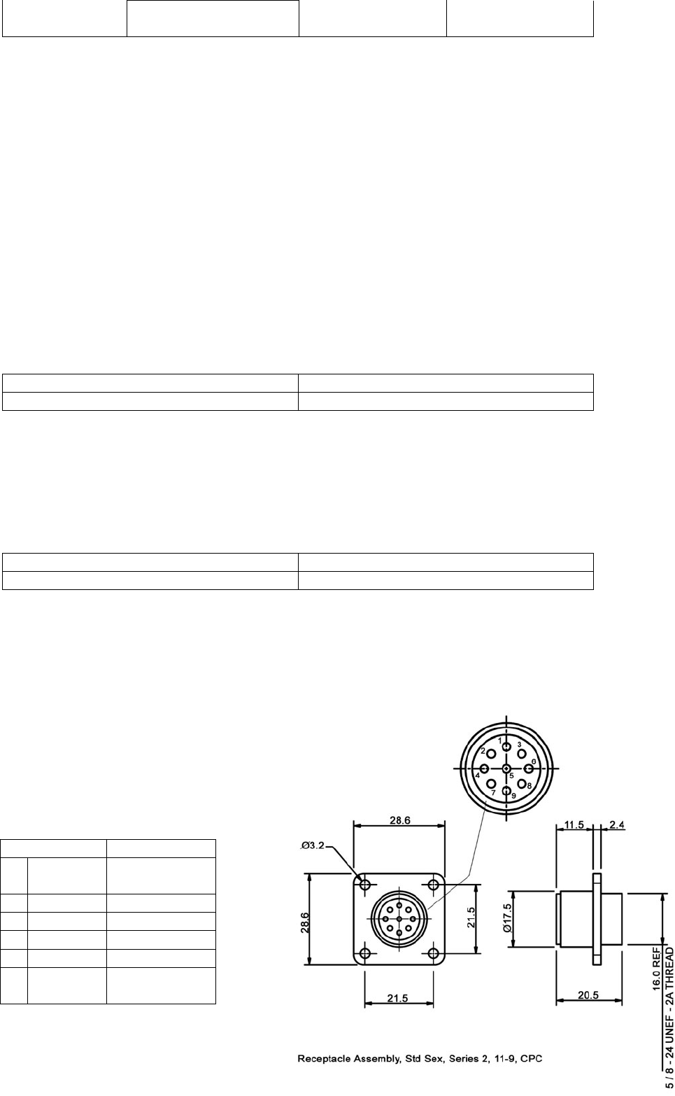
In the IMO installation guide for AIS transponders, the Pilot plug is recommended to be:
• AMP/Receptacle (Square Flanged), Shell size 11, 9 pin Std. Sex 206486-1/2 or
equivalent and the termination shall be as illustrated in the table.
Transponder Pilot Plug
1RxCOM No
Connection
2RxB Pin 6
3RxA Pin 5
4TxA Pin 1
5TxB Pin 4
6TxCOM No
Connection

S4-10 89-041 Section 4 Issue 5
LRF port, Long Range Function
The AIS Long-Range Function requires a compatible long-range communication system e.g.
Inmarsat-C. If this is available, a connection to the Inmarsat-C system can be made. It is
required that the Inmarsat-C input/output port can be interfaced using IEC 61162-2 and
understand the long-range sentences as required by IEC 61993.
Recommended cable for connection of LRF-port:
Three twisted pairs, shielded, PVC sheathed.
Cable length to display Required dimension
0 – 100 metres 0.8 mm2 each wire
LRF port wire connection
The twisted pairs shall be assigned as (RxA/RxB), (TxA/TxB) and (RxCom/TxCom)
RTCM port, Differential GNSS correction input/output port
The RTCM-port is the input/output port for differential correction. The UAIS Transponder can
receive differential correction in two ways:
• The RTCM port can be connected to a DGNSS unit. The DGNSS unit will then provide
differential correction to the AIS Transponder through the RTCM port.
• Through message 17 transmitted from a base station. The RTCM port will then work as
an output port, which can supply differential correction in RTCM format to other units.
Recommended cable for connection of RTCM-port:
Three twisted pairs, shielded, PVC sheathed.
Cable length to display Required dimension
0 – 100 metres 0.8 mm2 each wire
RTCM port wire connection
The twisted pairs shall be assigned as (RxA/RxB), (TxA/TxB) and (RxCom/TxCom)
BIIT, Built In Integrity Test relay function
The AIS requires that an alarm output (relay) be connected to an audible alarm device or to the
ships alarm system, if available.
If any failure or malfunction is detected that will significantly reduce integrity or stop operation of
the AIS, an alarm is initiated. In this case:
• An alarm message is displayed on the VDU
• The alarm BIIT relay shall is activated
• An appropriate alarm message is output via the presentation interface (Main and AUX-
ports) and repeated every 30 seconds.
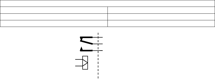
The UAIS transponder provides a relay connection, which can be selected as normal closed or
normal open contacts.
Recommended cable for connection of BIIT relay:
One twisted pair, shielded, PVC sheathed. The required cable dimension is dependent on
the current necessary to activate the alarm indicator.
89-041 Section 4 Issue 5 S4-11
Built in alarm (BIIT) relay ratings:
Absolute maximum ratings
Maximum switching current in contacts 0.25 Amp
Maximum carry current 1.20 Amp
Maximum switching voltage 175 V (d.c. or a.c. peak)
Completion of Installation
The foregoing provides the information necessary to perform the installation. Other useful
information is contained in the sections following.
The Pre-Installation Inspection Record (Section 8) should have been completed before
installation commenced.
It is most important that the installed system is not switched on at this stage. The
inspection procedures given in the Operation Manual must be completed before power is
applied.
The Warranty and Acceptance Record can only be completed after the system is configured, as
detailed in the Operation Manual.
Transponder Screw terminal board
N/C
Com
N/O

89-041 Section 5 Issue 5 S5-1
5 - Specification
General Data:
Power
consumption: 75W peak
21W average
Power supply: 24 VDC –10% +30%
AIS1 (CH87B) 161.975 MHz
AIS2 (CH88B) 162.025 MHz
Default
frequencies:
DSC (CH70) 156.525 MHz
Operating
temperature: -15°C to +55°C
Storage
temperature: -20°C to +70°C
Environmental: IEC 60945 Protected Environment
(Antennas: Exposed Environment)
Transponder
size/weight 308 x 416 x 93 mm, 7kg
VDU size/weight 219 x 151 x 76 mm, 1kg
GPS size/weight ∅ 115mm x 76mm, 0.25kg
GNSS receiver: Used for TDMA timing. Optionally used
for navigational information.
GNSS antenna: Patch antenna with built-in 30dB pre-
amplifier
GLONAS receiver Optional Glonass version available
DSC Transmitter:
Power output: 12.5 W or 2.0 W
Frequency range: 156.025 – 162.025 MHz
Antenna
impedance: 50 Ω
TDMA Receivers:
Sensitivity: (PER) < 10% at –107 dBm (25kHz)
Frequency range: 156.025 – 162.025 MHz
Channel spacing: 12.5 or 25 kHz
Modulation: GMSK
Data rate: 9,600 bits/s
Frequency stability: < ± 1ppm
DSC Receiver:
Sensitivity: BER <10-4 at 107 dBm
Frequency range: 155.3 – 162.5 MHz
Channel spacing 25kHz
Modulation 1300Hz/2100Hz - FSK
Frequency stability < ± 1ppm
Serial inputs/outputs:
SENS1/2/3 IEC61162-1/2 ( input only)
DISPLAY,
LONG RANGE,
MAIN,
AUX/PILOT, RTCM
IEC61162-1/2 (input & output)

S5-2 89-041 Section 5 Issue 5
Technical Information
RS-422 interfaces
The Transponder has seven RS-422 interfaces which are all available on the Screw Terminal
board:
• 3 sensor data input ports SEN1, SEN2 and SEN3
• 2 Bi-directional input/output ports MAIN and AUX/Pilot
• 1 Bi-directional input/output port RTCM
• 1 Bi-directional input/output port LR (Long Range)
All communication interfaces are compatible with IEC-61993-2 standards.
UAIS Interface Port Specification
Port Format O/P Sentence I/P Sentence
STD
Sentence
!AIVDO, !AIVDM, !AIABK,
!AIACA, $AITXT, $AIALR,
$AISSD, $AIVSD
$xxSSD; $xxVSD; $xxACA;
!xxABM; !xxBBM; !xxACK;
!xxAIR; !xxVDO; $xxAIQ,ACA;
$xxAIQ,HRST; $xxAIQ,SSD;
$xxAIQ,VSD
Unused
Fields None None
Main RS 422
IEC 61993-2
Proprietary None None
STD
Sentence Same as Main port Same as Main port
Unused
Fields None None
Aux/Pilot RS 422
IEC 61993-2
Proprietary None None
STD
Sentence !AILRF, !AILR1, !AILR2,
!AILR3 !xxLRI, !xxLRF
Unused
Fields None None
Long
Range RS 422
IEC 61993-2
Proprietary None None
STD
Sentence Binary stream as defined
in RTCM specification Binary stream as defined in
RTCM specification
Unused
Fields None None
RTCM
RTCM PAPER
11-98/SC104-
STD
(or compatible) Proprietary None None
STD
Sentence N/A DTM, GBS, GGA, GLL, GNS,
HDT, OSD, RMC, ROT, RTE,
VBW, VTG, WPL
Unused
Fields None None
Sensor 1 RS 422
IEC 61162-1/2
Proprietary None None
STD
Sentence N/A DTM, GBS, GGA, GLL, GNS,
HDT, OSD, RMC, ROT, RTE,
VBW, VTG, WPL
Unused
Fields None None
Sensor 2 RS 422
IEC 61162-1/2
Proprietary None None
STD
Sentence N/A DTM, GBS, GGA, GLL, GNS,
HDT, OSD, RMC, ROT, RTE,
VBW, VTG, WPL
Unused
Fields None None
Sensor 3 RS 422
IEC 61162-1/2
Proprietary None None

89-041 Section 5 Issue 5 S5-3
Termination
Termination resistors are required at each end of the RS-422 connection. The effect of the
termination is to increase the input loading of that port, as seen by the talker. The figures quoted
assume that the line is correctly terminated, and allow for that extra loading.
Output drive capability
Each talker output has a capability of driving a minimum of 12 listeners on a terminated cable.
Input loading
Each receiver presents a load of approximately 12kohm to the line. Line termination resistors
are 120 ohms.
Isolation
The interface isolation is 1kV minimum throughout.
Interpretation of IEC 61162-1 sentences
GPS and Sensor Input Sentences
DTM Datum Reference
If local code is other than WGS84, then the external position source is ignored.
Field Comment
Local Datum Code interpret If it’s WGS84 or not
Local Datum Subdivision Code Ignored
Lat Offset (2 fields) Ignored
Long Offset (2 fields) Ignored
Altitude Offset Ignored
Reference Datum Code Ignored
GBS - GNSS Satellite Fault Detection
If this sentence is received, the RAIM flag will be set to TRUE. It must be repeated at least once every 10 seconds.
Field Comment
UTC Time of GGA or GNS Checks if this field isn’t empty
Expected Error In latitude Checks if this field isn’t empty
Expected Error in longitude ignored
Expected error in altitude Ignored
ID number of most likely failed satellite Ignored
Probability of missed detection Ignored
Estimate of bias in meters Ignored
Standard Deviation of bias estimate ignored

S5-4 89-041 Section 5 Issue 5
GGA - Global Positioning System Fix Data
Field Comment
UTC Of Position used
Latitude (2 fields) Used
Longitude (2 fields) Used
GPS Quality Indicator Used,
I ,3-> Position with Low Accuracy
2,4,5 -> Position with High Accuracy
6 -> Dead Reckoning with Low Accuracy
7 -> Manual mode with low accuracy
OTHER -> No Position
Number of Satellites in use ignored
Horizontal Dilution of precision (HDOP) ignored
Altitude re: main sea level (2 fields) ignored
Geoidal Separation (2 fIelds) Ignored
Age of Diff Data Ignored
Diff Reference Station Ignored
GLL - Geographic Position - Latitude I Longitude
Field Comment
Latitude (2 fields) Used
Longitude (2 fIelds) Used
UTC of Position used
Status Used
A-> Allows look on Mode indicator or
Position with Low Accuracy if Mode
indicator is empty or has strange value
V-> Disallows using the sentence
Mode Indicator A -> Position with Low Accuracy
D -> Position with High Accuracy
E -> Dead Reckoning Mode with Low
Accuracy
M -> Manual Mode with Low Accuracy
Empty or OTHER.> using Status only
GNS - GNSS Fix Data
If the Mode Indicator is a NULL field, the sentence is ignored.
Field Comment
UTC of Position used
Latitude (2 fields) Used
Longitude (2 fields) Used
Mode Indicator A, P> Position with low accuracy
D, R, F -> Position with high Accuracy
E -> Dead Reckoning Mode with Low
accuracy
M -> Manual Mode with low accuracy
OTHER -> No Position
Tot Number of Satellites in Use Ignored
HDOP Ignored
Antenna Altitude Used in aircraft mode else Ignored
Geoidal Separation Ignored
Age Of Diff Data Ignored
Diff Reference Station ID Ignored

89-041 Section 5 Issue 5 S5-5
HDT - Heading, True
The use of this sentence is talker identifier dependent.
Field Comment
Heading Used If Valid indicator is T
Valid Indicator Used
OSD- Own Ship Data
Field Comment
Heading, Degrees TRUE Used if heading status Is ‘A’
Heading Status Used
Vessel Course Used as COG if reference is B,R or P
Course Reference Used
Vessel Speed Used as SOG if reference is B,R or P
Speed Reference Used
Vessel Set Ignored
Vessel Drift ignored
Speed Units Used to convert SOG to knots
RMC - Recommended Minimum Specific GNSS Data
Field Comment
UTC of Position Fix Used
Status Used as in GLL
LatItude (2 fields) Used
Longitude (2 fields) Used
SOG, knots Used
COG, degrees Used
Date Ignored
Magnetic Variation (2 fields) ignored
Mode Indicator Used as in GLL
ROT - Rate Of Turn
The rate of turn value is only used if the talker identifier is TI.
Otherwise the value is only used to determine the direction, i.e. “Moving Right” or “Moving Left”.
Field Comment
Rate of turn Used when status is A. The value is rounded
to the closest integer.
Status Used

S5-6 89-041 Section 5 Issue 5
VBW - Dual Ground I Water Speed
The current position source must be external GPS, and heading must be available for the transponder to accept this
sentence.
Field Comment
Longitudinal Water Speed Ignored
Transverse Water Speed Ignored
Status: Water Speed Ignored
Longitudinal Ground Speed Used if Status is set to A
Transverse Ground Speed Used if Status is set to A
Status: Ground Speed Used
Stern Transverse Water Speed Ignored
Status Stern Water Speed Ignored
Stern Transverse Ground Speed Ignored
Status Stern Ground Speed ignored
VTG - Course Over Ground and Ground Speed
Field Comment
COG, degrees True (2 fields) Used
COG, degrees Magnetic (2 fields) ignored
SOG, knots (2 fields) Used
SOG, km/h (2 fields) Ignored
Mode Indicator Used
AIS Specific Input Sentences
ABM - Addressed Binary and safety-related Message
Field Comment
Total Number of Sentences Used if in interval 1 ..9, otherwise the sentence is ignored
Sentence Number Used if in interval 1. .total sentences, otherwise the sentence
Is ignored
Sequential Message Identifier Used if in Interval 0..3, otherwise the sentence is ignored
MMSI of Destination Used
AIS Channel Used
Message Id Used If 6 or 12, otherwise the sentence is ignored
Encapsulated Data Used
Number of filled bits Used

89-041 Section 5 Issue 5 S5-7
ACA - MS Regional Channel Assignment Message
The zone created of this sentence must be accepted by the channel management rules (size of zone, distance to
own position, valid channel number etc). If the zone isn’t accepted, the zone will be ignored
Field Comment
Sequence Number Ignored
NE Latitude (2 fields) Used
NE Longitude (2 fIelds) Used
SW Latitude (2 fields) Used
SW Longitude (2 fields) Used
Transitional Zone Size Used
Channel A Used
Channel A Bandwidth Used
Channel B Used
Channel B Bandwidth Used
Tx/Rx Mode Used
Power Level Used
In Use Flag Ignored
Time of In Use Change Ignored
ACK - Acknowledge Alarm
Field Comment
ID of the alarm source Used
AIQ - Query Sentence
Field Comment
Approved sentence formatter of data being
requested It’s possible to query the following sentences:
ACA, SSD, VSD,HRST
AIR - AIS Interrogation Request
This sentence may be used to perform a “UTC Request”. It is always sent on both Channel A and Channel B, for the
reason that this is a multiple addressed sentence.
Field Comment
MMSI 1 Used, may be NULL
Message Id 1.1 Used, may be NULL
Message Sub Section ignored
Message Id 1.2 Used, may be NULL
Message Sub Section Ignored
MMSI 2 Used, may be NULL
Message Id 2.1 Used, may be NULL
Message Sub Section ignored

S5-8 89-041 Section 5 Issue 5
BBM - Broadcast Binary Message
Field Comment
Total Number of Sentences Used if in interval 1 ..9, otherwise rejected
Sentence Number Used if In interval 1…[total number of sentences],
otherwise rejected.
Sequential Message Identifier Used If in interval 0..9, otherwise rejected
AIS Channel Used
Message Id Used if 8 or 14
Encapsulated Data Used
Number of filled bits Used
SSD - Ship Static Data
Field Comment
Call Sign Used, may be NULL
Name Used, may be NULL
Pos Ref A Used to change position reference for the position source
in use. May be NULL.
Pos Ref B Used to change position reference for the position source
in use. May be NULL.
Pos Ref C Used to change position reference for the position source
in use. May be NULL.
Pos Ref D Used to change position reference for the position source
In use. May be NULL.
DTE Used
Source Identifier Ignored
VSD - Voyage Static Data
Field Comment
Type Of Ship And Cargo Used
Maximum Present Draught Used
Persons On-Board Used
Destination Used
Est. UTC of arrival Used
Est. Day of arrival Used
Est. Month of arrival Used
Navigational Status Used
Regional Application Flags Ignored

89-041 Section 6 Issue 4 S6-1
6 - Serial interface communications protocols
As previously stated, the Transponder has seven RS-422 interfaces which are all available on
the Screw Terminal board:
• 3 sensor data input ports SEN1, SEN2 and SEN3
• 2 Bi-directional input/output ports MAIN and AUX/Pilot
• 1 Bi-directional input/output port RTCM
• 1 Bi-directional input/output port LR (Long Range)
Sensor data interface
The Sensor data input ports receive navigational data in NMEA–0183 format from the
connected sensors. The connected sensors can be a GNSS unit used for navigation, a
gyrocompass and a bottom track log. These data are processed in the UAIS unit and
transmitted as dynamic data. The data received by other stations over the VHF link form an
image of the sensor data. It is therefore vital that the sensor data are correct and that the port is
correctly configured.
The sensor ports of the UAIS Transponder understand the following IEC 61162 sentences. The
priority order of listing is left to right:
Latitude & Longitude: GNS, RMC, GGA, GLL
Speed Over Ground: VBW, RMC, VTG, OSD
Course Over Ground: RMC, VBW, VTG, OSD
Heading: HDT, OSD
Rate Of Turn: ROT, calculated from heading (HDT, OSD).
Navigational data must be received via the sensor ports within certain intervals; the maximum
intervals are listed in the table below. If NMEA sentences containing identical information arrive
at the sensor input ports, the UAIS Transponder will choose the information with the highest
priority level.
The built-in GNSS unit will under normal conditions only be used for TDMA slot timing. However
if no data are received from the external sensors, the built-in GNSS unit can be set to take over
automatically and supply navigational information for the VHF data link transmission. The
changeover between internal GNSS information use and external sensor information use
happens automatically, information received from the external sensors has priority and will
always be used when available.
List of messages received from sensors
Data type Max update
interval [s] NMEA application Default parameter value
Date 3 RMC Year 2000, month. 0, day 0
UTC 3 GNS, RMC, GGA,
GLL 24:60:60
Lat, Lon 3 GNS, RMC, GGA,
GLL 91°00′00″ nl, 181°00′00″ wl
Datum 30 DTM Not defined
SOG,
COG 3 RMC, VBW, OSD 102.3, 360°
Altitude 3 GNS 4095
Heading 10 HDT 511
Turn rate 10 ROT -128
RAIM 10 GBS Ok
S6-2 89-041 Section 6 Issue 4
Route plans with positions are transmitted in RTE (Routes) and WPL (Waypoint location)
sentences. There is no update interval for these data, therefore the last updated Route plan will
be kept in memory until data are updated or the power is switched off, as the data are not kept
in the permanent memory.
The UAIS Transponder will only accept the RTE sentence if the “w” attribute is in its 4th field
(current Route plan). WPL sentences can be sent before or after the RTE sentence. The
Transponder supports memory space for 22 Route plan positions; inactive positions are
gradually removed from memory and replaced with new data.
Main and AUX port reception and transmission of UAIS data
Specific UAIS Transponder functions are available via the Main and AUX ports. The ports are
identical and will transmit all received VDL (VHF Data Link) messages as well as Transponder
error messages. A request for information may be sent from equipment connected to the Main
and AUX ports, ether a request for information or a request for the Transponder to carry out a
specific task. The communication protocol is text, but in non-readable sentences which contain
compressed binary data.
The Transponder Main/AUX input port can accept requests:
• To send a short text message or a small binary data array to a specified address
(MMSI) or as a broadcast message
• To send a static or voyage information request to a specified address (MMSI)
• To change AIS radio frequencies and/or parameters of access to AIS channels
(radiating power, frequency band etc.)
The Transponder Main/AUX input port can accept:
• Static and voyage related data
• Navigation or dynamic data, similar to sensors data interface
• Error situation message acknowledgement.
The Transponder Main/AUS output port can transmit:
• Notifications about every VHF message received and transmitted via AIS channels
with the VHF message included;
• Acknowledgement of requests from other stations;

89-041 Section 7 Issue 4 S7-1
7 - Warranty Registration & Acceptance Record
IMPORTANT! To validate product warranty, please fax a completed copy of this form to: -
McMurdo Customer Services on +44 23 9262 3824
Vessel Data
Vessel Name Flag State
Owner / Company Radio Call Sign
Office:
On-Board Contact
Name Telephone
Number(s) GSM:
Office:
Superintendent’s
Name Telephone
Number(s) GSM:
Installers Data
Company Name Stamp:
Technician’s Name
Address Line 1
Address Line 2
City / Town
Province / State
Post / Zip Code
Country
Scope Of Supply
Part No. Description Serial No. QTY Location
89-051-001A Transponder
89-052-001A VDU
89-021-001A GPS Antenna
89-020-001A VHF Antenna
903-01 Mast Bracket
903-02 Mast/Bulkhead Bkt.
89-028 Gyro Interface Unit
89-029 AC/DC Converter
89-038 Installation Kit
89-362 GPS Antenna Adapter
This is an acceptance record of the installation and commissioning of the UAIS on-board
the above-mentioned vessel. 24-months Warranty is valid on signing this form.

S7-2 89-041 Section 7 Issue 4
Note: The order of the following information is that in which it appears on the VDU
General Set-up
MMSI (Maritime Mobile Service Identity)
IMO (International Maritime
Organisation) IMO
RAIM Present (Automatically Selected) Yes No
Set-up password (Max. 8 Characters)
Addressed message filter (Automatically
Selected) On Off
Media analyser mode (Automatically
Selected) On Off
Max. repeating message 6, 12 4 (default)
Transmission w/o sync Yes No
Enable deleting regions Yes No
Extra Set-up
Internal GNSS position Enabled Disabled
Distance Internal GNSS to Bow Metres
Distance Internal GNSS to Stern Metres
Distance Internal GNSS to Port side Metres
Distance Internal GNSS to Starboard Metres
Out position to MAIN & AUX Yes No
Alarm Signals
Tx malfunction On (default) Off
Antenna VSWR exceeds limit On (default) Off
Rx channel A malfunction On (default) Off
Rx channel B malfunction On (default) Off
Rx channel DSC malfunction On (default) Off
General failure On (default) Off
VDU connection lost On (default) Off
External EPFS lost On (default) Off
No sensor position in use On (default) Off
No valid SOG information On (default) Off
No valid COG information On (default) Off
Heading lost / invalid On (default) Off
No valid ROT information On (default) Off
No TDMA synchronisation On (default) Off
Tx Amplifier malfunction On (default) Off
No own reports mode On (default) Off
89-041 Section 7 Issue 4 S7-3
RS-422 Set-up
Port General Baud rate Parity Stop
bits
Main On Off 1200 2400 4800 9600 38400 None Odd Even 1 2
Aux On Off 1200 2400 4800 9600 38400 None Odd Even 1 2
LR On Off 1200 2400 4800 9600 38400 None Odd Even 1 2
RTCM On Off 1200 2400 4800 9600 38400 None Odd Even 1 2
Sen 1 On Off 1200 2400 4800 9600 38400 None Odd Even 1 2
Sen 2 On Off 1200 2400 4800 9600 38400 None Odd Even 1 2
Sen 3 On Off 1200 2400 4800 9600 38400 None Odd Even 1 2
DNSS Broadcasting Set-up
Ref. Station 0 ID
Latitude
Longitude
Ref. Station 1 ID
Latitude
Longitude
Transmission Disable On Channel 1 On Channel 2 Alternate Channels
Installer’s Signature Owners Representative’s
Signature Commissioning Date
Installer’s Name Owners Representative’s
Name

89-041 Section 8 Issue 4 S8-1
8 - Pre-Installation Inspection Record
1. Vessel Data ( Tick appropriately )
Vessel Name IMO Number
Flag State MMSI Number
Owner / Company Radio Call Sign
Office:
On-Board Contact
Name & Position
Telephone Number(s)
GSM:
Office:
Shore-based Contact
Name & Position
Telephone Number(s)
GSM:
Type of Vessel Gross Tonnage gt
L.O.A mBeam m
Comments:
2. Installation ( Tick appropriately )
Ship’s Emergency Power Source & Location
Cable length to Transponder = m
Optional AC to DC Converter (89-029) Required
12VDC 24VDC 110VAC 220VAC
50Hz 60Hz
UAIS Transponder Proposed Location
UAIS Display Proposed Location
4 Twisted Pair + Drain Cable length to Transponder m
UAIS GNSS Antenna Proposed Location
RG58 Cable length to Transponder = m
Optional Antenna Adapter (89-362) Required
UAIS VHF Antenna Proposed Location
RG214 Cable length to Transponder = m
Optional VHF Antenna (89-020-001) Required
Optional Antenna Mast Mount (903-01) Required
Optional Antenna Mast/Bulkhead Mount (903-02) Required
UAIS Pilot Plug* Proposed Location
Cable length to Transponder = m
Ship’s Ground Connection Location
Cable length to Transponder = m
Ship’s Alarm Panel Location
Cable length to Transponder = m
* If a Pilot Plug is fitted, a mains power supply for a PC should be made available nearby
Optional Installation Kit (89-038) Required
Comments:

S8-2 89-041 Section 8 Issue 4
Bridge Layout Drawing: Position of all parts & interface pick-off points
3. Heading Sensor(s)* ( Tick appropriately )
Source Option A Option B
Manufacturer
Model
Type GyroCompass GNSS Compass
Fluxgate Compass
Transmitting Magnetic Compass
GyroCompass GNSS Compass
Fluxgate Compass
Transmitting Magnetic Compass
Output NMEA Message
IEC 61162-2 RS422
Required:- HDT ROT**
Optional:- OSD
Required:- HDT ROT**
Optional:- OSD
If no NMEA
Optional Gyro Interface
Unit (89-028) Required
Synchro
Reference Voltage =
Phase Voltage = Frequency =
Ratio - 90:1 180:1 360:1
Synchro
Reference Voltage =
Phase Voltage = Frequency =
Ratio - 90:1 180:1 360:1
Stepper
Positive Step Negative Step
Step Voltage =
Ratio - 90:1 180:1 360:1
Stepper
Positive Step Negative Step
Step Voltage =
Ratio - 90:1 180:1 360:1
Location
Cable length to
Transponder mm
* Heading information is a mandatory sensor input to the UAIS. A converter will be needed if the ship’s compass has no IEC61162 output.
** If a rate-of-turn indicator is available and it includes an IEC61162 output it should be connected to the UAIS
Comments:

89-041 Section 8 Issue 4 S8-3
4. Position Sensor(s)* ( Tick appropriately )
Source Option A Option B
Manufacturer
Model
Type GPS GLONASS Differential GPS GLONASS Differential
Output NMEA Message
IEC 61162-2 RS422
Required:- DTM GNS GLL
RMC GBS RTE WPL
Optional:- GGA
Required:- DTM GNS
GLL RMC GBS RTE
WPL
Optional:- GGA
Location
Cable length to
Transponder mm
Antenna Location External Position Source
GNSS Antenna UAIS Internal Position
Source GNSS Antenna Dimension
Limits
A = Distance to Bow mm
0- 511m
B = Distance to Stern mm
0 - 511m
C = Dist. to Port-Side mm
0 - 63m
D = Dist. to Starboard mm
0 - 63m
* Position information is a mandatory sensor input to the UAIS.
Comments:
5. Speed Sensor(s)* ( Tick appropriately )
Source Option A Option B
Manufacturer
Model
Type Bottom Track Log Bottom Track Log
Output NMEA Message
IEC 611622-2 RS422
Required:- VBW Required:- VBW
Location
Cable length to
Transponder mm
* If a Bottom Track Log is available and it includes an IEC61162 output it should be connected to the UAIS.
Comments:

S8-4 89-041 Section 8 Issue 4
6. ARPA / ATA RADAR(s) ( Tick appropriately )
Source Option A Option B
Manufacturer
Model
Type
In/Output NMEA
Message
IEC 61162-2 RS422
Location
Cable length to
Transponder mm
Comments:
7. ECDIS / ECS(s) ( Tick appropriately )
Source Option A Option B
Manufacturer
Model
Type
In/Output NMEA
Message
IEC 61162-2 RS422
Location
Cable length to
Transponder mm
Comments:
8. Notes
Include comments relative to installation: Cable routing, Deck glands to be opened, Hot work required, Interfacing, Mounting, Earthing,
etc…

89-041 Section 9 Issue 4 S9-1
9 - Glossary
4S Ship-to-Ship & Ship-to-Shore
AIS Automatic Identification System
ALM Alarm
ANT Antenna
ARPA Automatic Radar Plotting Aid
ATA Automatic Tracking Aid
AtoN Aid to Navigation
AUTO Automatic
AUX Auxiliary
BAT Battery
BIIT Built-In Integrity Test
BRG Bearing
BRILL Display Brilliance
CG Coast Guard
CH Channel
CHG Change
CLR Clear
CNCL Cancel
CNS Communication, Navigation & Surveillance
COG Course Over Ground
CONTR Contrast
CPA Closest Point of Approach
CPU Central Processing Unit
CSE Course
DEL Delete
DEST Destination
DG Dangerous Goods
DGLONASS Differential GLONASS
DGNSS Differential GNSS
DGPS Differential GPS
DISP Display
DIST Distance
DSC Digital Selective Calling
DTE Data Terminal Equipment
ECDIS Electronic Chart Display and Information
System
ECS Electronic Chart System
EGNOS European Geo-stationary Navigational
Overlay System
ENC Electronic Navigation Chart
ENT Enter
EPA Electronic Plotting Aid
EPFS Electronic Position Fixing System
EPIRB Electronic Position Indicating Radio
Beacon
ERR Error
ETA Estimated Time of Arrival
EXT External
FCC Federal Communications Commission
FREQ Frequency
GLO or
GLONASS Global Orbiting Navigation Satellite
System
GMDSS Global Maritime Distress and Safety
System
GND Ground
GNSS Global Navigation Satellite System
GPS Global Positioning System
GYRO Gyro Compass
HDG Heading
HS Hazardous Substances
HSC High Speed Craft
I/O Input / Output
IBS Integrated Bridge System
ID Identification
IEC International Electotechnical Commission
IMO International Maritime Organisation
IN Input
INFO Information
INS Integrated Navigation System
ITU-R International Telecommunications Union –
Radiocommunications Bureaux
KN Knots
L/L Latitude / Longitude
LAT Latitude
LON Longitude
LOST TGT Lost Target
MMetres
MAG Magnetic
MAN Manual
MED Marine Equipment Directive
MF/HF Medium Frequency/High Frequency
MID Maritime Identification Digit
MIN Minimum
MKD Minimum Keyboard and Display
MMSI Maritime Mobile Service Identity
MOB Man Overboard
MP Marine Pollutant
NAV Navigation
NM Nautical Mile
NUC Not Under Command
OOW Officer Of the Watch
OS Own Ship
OUT Output
POSN Position
PPU Portable Pilot Unit
PWR Power
RAIM Receiver Autonomous Integrity Monitoring
RNG Range
RORO Roll On, Roll Off
ROT Rate Of Turn
RR Range Rings
RTCM Radio Technical Commission for Maritime
services
RTE Route
Rx Receive / Receiver
SAR Search And Rescue
SEL Select
SOG Speed Over Ground
SPD Speed
SPEC Specification
STBD Starboard
STBY Standby
STW Speed Through Water
TCPA Time to Closest Point of Approach
TDMA Time Division Multiple Access
TGT Target
TPR Transponder
TRK Track
TSS Traffic Separation Scheme
TTG Time To Go
Tx Transmit / Transmitter
Tx/Rx Transceiver
UAIS Universal Automatic Identification System
UHF Ultra High Frequency
UTC Universal Time Co-ordinate
VDU Visual Display Unit
VHF Very High Frequency
VOY Voyage
VSWR Virtual Standing Wave Ratio
VTS Vessel Traffic Systems
WAAS Wide Area Augmentation System
WCV Waypoint Closure Velocity
WGS World Geodetic System
WIG Wing In Ground
WPT Waypoint
S3-10 89-041 Section 3 Issue 4
2.
3.
External illumination
The VDU does not require external illumination during operation, as it has an internal backlight;
the use of on-screen keys ensures that all controls are visible in the screen backlight.
However, it is recommended that some form of illumination, possibly temporary, is provided
during installation and maintenance.
Refer to previous page for illustration of
fitted clamping screw
89-041 Section 3 Issue 4 S3-11
Antenna units
The UAIS Transponder has to be connected to two antennas: a VHF antenna and a GNSS
antenna.
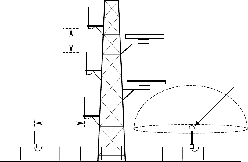
Antenna mounting position
In accordance with IMO guidelines, antennas should be mounted in positions which, as far as
possible, minimise interaction between them. The sketch summarises the recommendations:
VHF antenna
The VHF antenna is an important part of the receiver and transmitter system; the reception
range is heavily dependent on the antenna installation. The VHF antenna must be installed as
high as possible and free of shadow effects from the ship superstructure; effective installation
will maximise the range of the system. The antenna must also be mounted so as to achieve the
safety standards detailed on Page 3 of the Preface.
WARNING: The antenna must have sufficient bandwidth to suit the UAIS system, as otherwise
the high VSWR produced may cause the transponder to shut down. It is recommended to use
an omni-directional vertical polarised VHF antenna with a gain of 3 – 5 dBi, and a bandwidth
sufficient to maintain VSWR <1.5 over the frequency range 156 – 163MHz. A suitable antenna
is available from McMurdo as an option, part number 89-020-001.
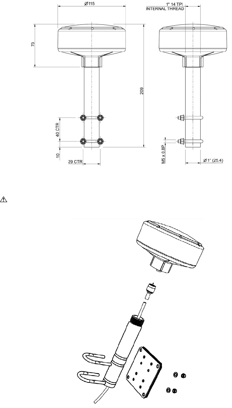
GNSS antenna
The Transponder package contains a GNSS antenna and a mounting bracket. The mounting
bracket is designed for welding to the ship’s superstructure.
Installation of the GNSS antenna is critical for the performance of the GNSS, which is used for
timing of the transmitted time slots and for the supply of navigational information should the
main navigational GNSS fail.
1. The GNSS antenna must be mounted in an elevated position and free of shadow effect
from the ship’s superstructure
2. The GNSS antenna must have a free view through 360 degrees with a vertical angle of 5
to 90 degrees above the horizon.
V
ertical
separation
2m
Horizontal
separation
10m
GNSS antenna
180°
360°
S3-12 89-041 Section 3 Issue 4
3. As the received GNSS signal is very sensitive to noise and interference generated by
other onboard transmitters, ensure that the GNSS antenna is placed as far away as
possible from Radar, Inmarsat and Iridium transmitters. Ensure the GNSS antenna is free
from direct view of the Radar and the Inmarsat beam
WARNING: Screw the rod into the GNSS antenna by turning the rod. Do not turn the GNSS
antenna as this will twist the cable and damage the connection.
89-041 Section 3 Issue 4 S3-13
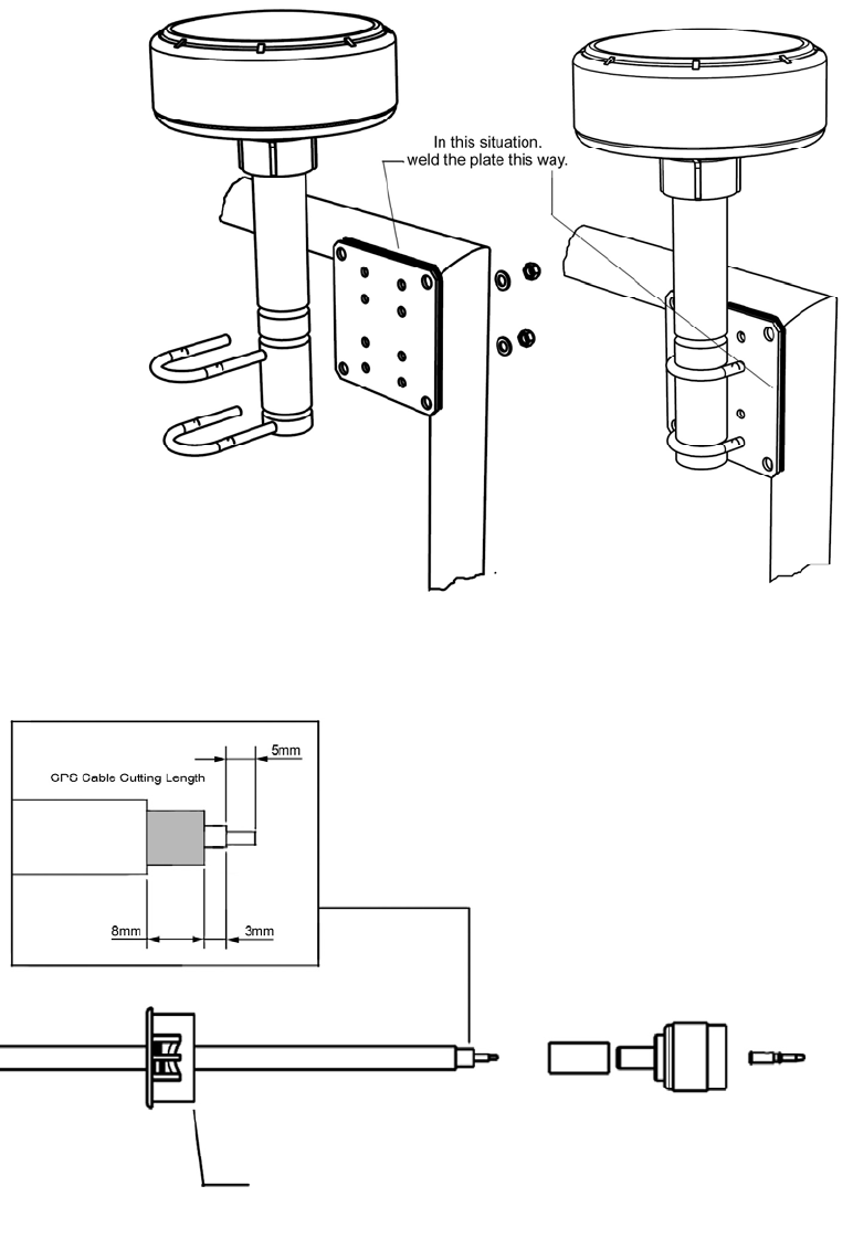
Weld on plate mounting of the GNSS antenna
Cable Preparation
Ensure grommet is fitted before connector
S3-14 89-041 Section 3 Issue 4
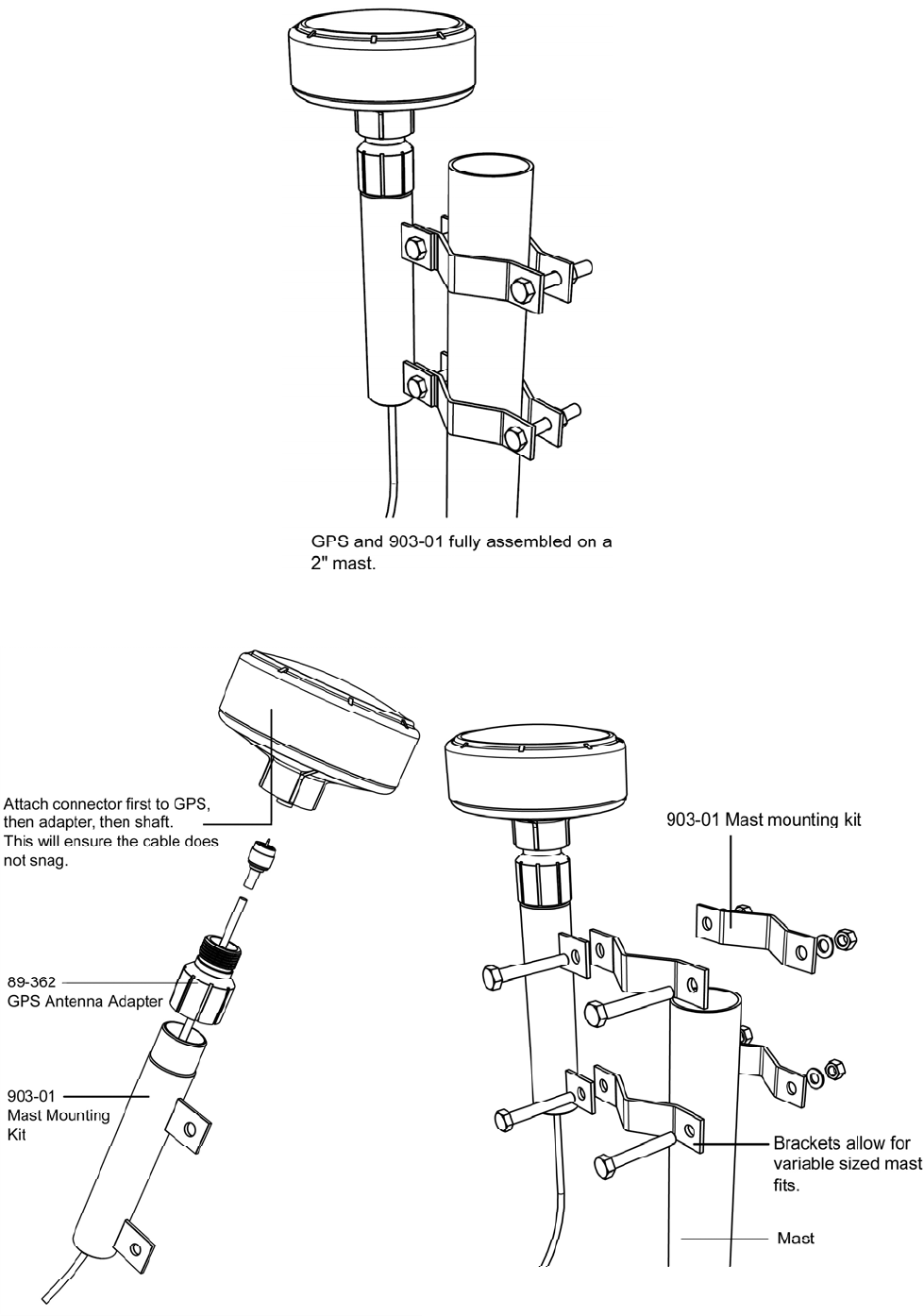
Mast assembly for GNSS antenna
Note: The GPS Antenna
A
dapter, P/N 89-362, is
required to mount a GPS
antenna on the Antenna
Bracket 903-01. VHF
antennas mount directly on
the bracket.

89-041 Section 4 Issue 5 S4-1
4 - Electrical connections
This installation guide takes into account the IMO “Guidelines for installation of Shipborne
Automatic Identification System”. However both the IMO publication and these instructions must
be taken as guidance only; individual circumstances must take precedence.
This guide is concerned only with the installation of the UAIS transponder unit and does not
cover the installation of any peripheral equipment connected to the transponder. For proper
installation and connection of peripheral equipment to the transponder refer to the installation
manual for these products.
Connection Must connect Optional
24.0 VDC power supply Yes
GNSS antenna Yes
VHF antenna Yes
Display system (VDU) Yes
Pilot plug Yes
Alarm Relay Yes (if available)
ECDIS (Main port) Yes
ARPA (Main port) Yes
Long range function Yes
RTCM, differential GNSS info. Yes
Position Yes
Heading Yes
Rate of turn Yes
Speed and Course Yes
Installation kit (optional)
This installation kit comprises the following:
Item Quantity
Power Cable, 2.5mm 2-core flex 20m
VHF antenna cable, RG214 Coax 30m
GPS antenna cable, RG58 Coax 30m
Signal cable, 0.5mm 4 twist pair + drain 60m
Cable tie 200
Cable marker 20
Crimp tool 1
Tape, self-amalgamating 2 reels
Signal cable connections for UAIS Transponder
As shown in the table above, the UAIS Transponder must be or may be connected to different
types of peripheral units; these can be divided in three groups:
• Coax connection to the antennas
• signal cable connection to the sensors (GNSS, Gyro, Log)
• signal cable connections to the five-input/output ports (Main, AUX/Pilot, long-range,
RTCM, Display)
Connecting the three types of interfaces is described in detail in the following chapters.
The signal connections are all connected via a serial RS422 type interface; baud rates are from
1200 to 38400.
In some cases, particularly in retrofit installations, it may not be possible to connect the UAIS
directly to the required sensor, because some sensors do not provide the IEC 61162-2 (NMEA)
sentences required by the UAIS unit. In such cases a protocol converter is required between the
sensor and the UAIS unit. Converters are available from different manufacturers, either as direct
S4-2 89-041 Section 4 Issue 5
protocol converters or frequently as repeater instruments for the sensor. A Gyro Interface Unit,
P/N 89-028, is available from McMurdo as an optional extra.
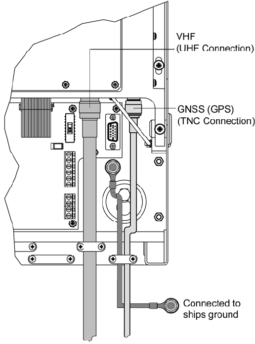
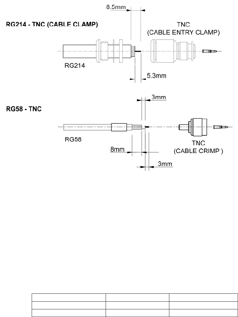
VHF and GNSS (GPS) antenna cable connections
The VHF and the GNSS antenna cables are connected directly to the transponder through a
UHF and a TNC plug respectively.
The coax cable plugs must be attached directly to the cables; the outer insulation must not be
connected in the cable cleat but in the coax plug as illustrated below.
VHF antenna
The VHF antenna is an important part of the receiver and transmitter system; the reception
range is heavily dependent on the antenna installation. It is recommended to use an omni-
directional vertical polarised VHF antenna with a gain of 3 – 5 dB. The VHF antenna must be
installed as high as possible and free of shadow effects from the ship superstructure; effective
installation will maximise the range of the system.
In accordance with the IMO guidelines, an exclusion zone is defined around a VHF antenna;
other antennas must be mounted outside this zone.
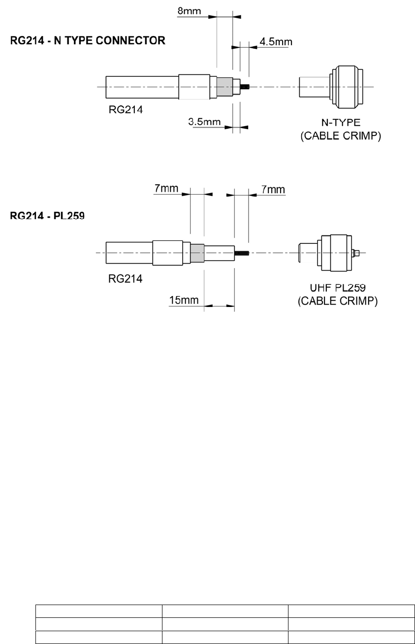
To make sure that the transmitted and received VHF signal is not interfering with Radar signals,
other VHF transmission or power lines it is important that the connection between the VHF
antenna and the transponder is of a high quality double shielded coax cable. It is recommended
to use a RG214 cable and PL259 or N-type connectors.
If the cable has to be longer than 40 metres, it is recommended to use a cable with lower loss; a
40 metre RG214 coax cable has a signal attenuation of 3 dB at 150MHz, thus the signal
strength is reduced to half its value due to cable attenuation.
89-041 Section 4 Issue 5 S4-3
GNSS (GPS) antenna
The GNSS (GPS) antenna has to have a clear view of the sky, the objective is to see the
horizon freely through 360 degrees with a vertical view of 5 to 90 degrees above the horizon.
As the received GNSS signal is very sensitive to noise and interference generated by other
onboard transmitters ensure that the GNSS antenna is placed as far away as possible from
Radar, Inmarsat and Iridium transmitters. Ensure the GNSS antenna is free from direct view of
the Radar and the Inmarsat beam.
It is also important that the MF/HF and other VHF transmitter antennas are kept as far away as
possible from the GNSS antenna. It is good practice never to install a GNSS antenna within a
radius of 5 meters from these antennas.
The GNSS operates in the ultra high frequency band (1.575 GHz). The signal attenuation in
cables is therefore substantial and has to be taken into account when the coax cable between
the antenna and the UAIS unit is chosen. To compensate for this signal attenuation the supplied
GPS antenna includes a pre-amplifier with a gain of 36 dB.
The optimum combination of coax cable and GPS antenna gain will have a resulting installation
gain (pre-amplifier–cable attenuation) within 0 to 10 dB. The table below shows examples of
coax cables.
Cable description Attenuation / 100metre Maximum cable length
RG 58 70 dB @ 1.5GHz 40 metres
RG214 37 dB 90 metres
Connectors used must be TNC throughout.
S4-4 89-041 Section 4 Issue 5
Screw terminal board
The UAIS Transponder has a build in screw terminal board which makes it very easy during
installation to connect cables to the power sources, to sensors, to the VDU and to other display
units through the Main and AUX ports.
Refer to the wiring diagram, attached as an appendix, for details of connections to the screw
terminal board.
Fuse values
The main system fuse (10 amp) is located on the screw terminal board. A separate fuse (1 amp)
on the screw terminal board protects the VDU. Both power supplies are reverse polarity
protected.
Fuse description Fuse value Part No.
Main system fuse 10.0 Amp 99-077
VDU system fuse 1.0 Amp 99-076
Signal line termination
Signal lines may need termination by a resistor across the inputs. These resistors are
incorporated on the screw terminal board and can be switched in or out by the switches S2, S4,
S5, S6, S7, S8. The switches are identified on the Screw Terminal Board diagram on Page 6.
Note:
1. Each switch is a double unit
2. S2 and S5 each control two signals individually
3. S4, S6, S7 and S8 – both switches should be moved together
4. S3 has been deleted
89-041 Section 4 Issue 5 S4-5
Whether termination at the terminal board is required depends on how the other units are
connected, and whether any of these other units provides termination for the signal line. The
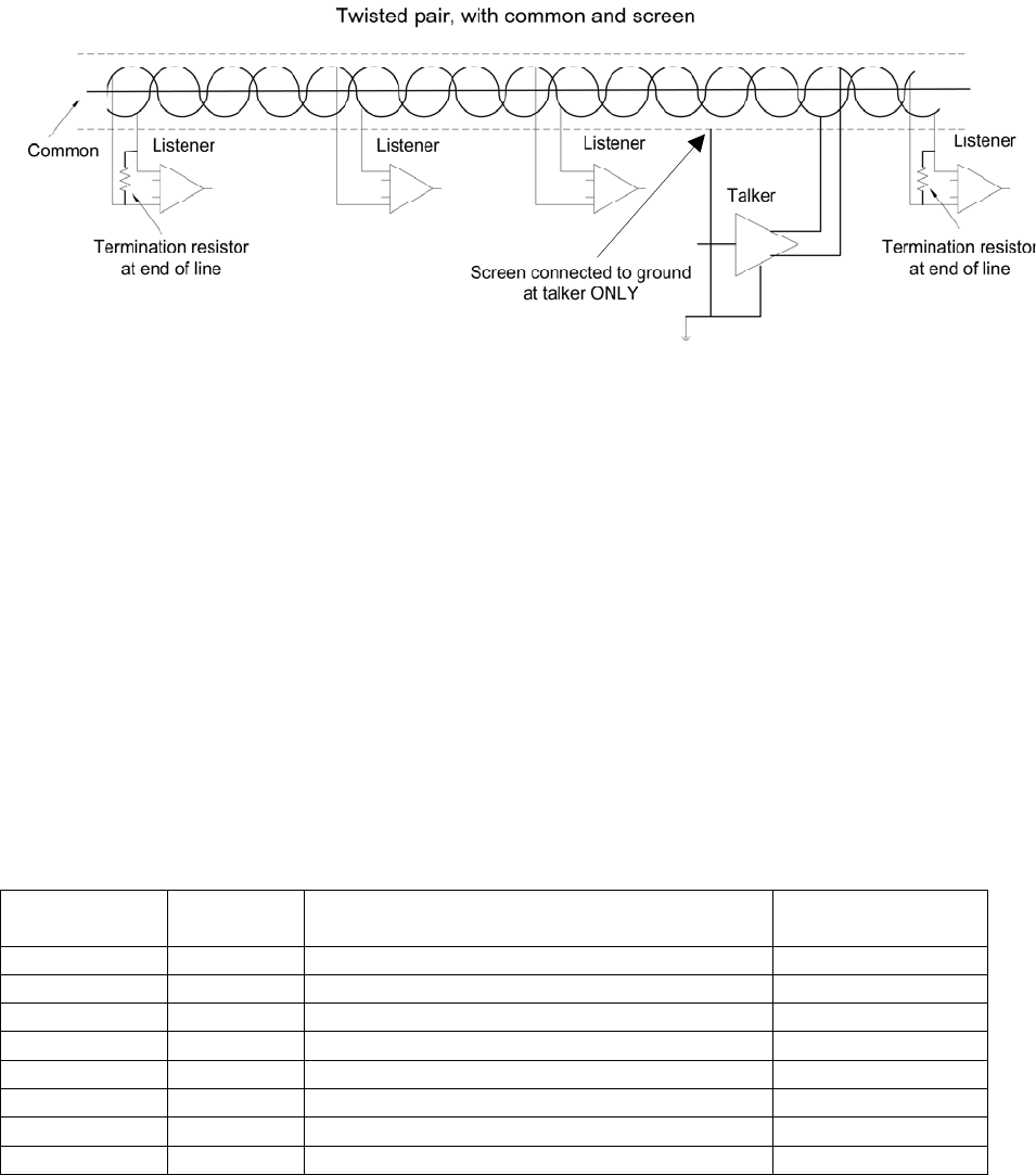
following sketch shows the principle:
There is only one talker per twisted pair; there can be several listeners. The requirement is that
terminations must be provided by the devices at the ends of the line, regardless of whether they
are listeners or the talker, and that no other device should provide a termination.
A terminal is provided for the common connection at each port on the screw terminal board;
particular care should be taken to ensure that the cable screen is connected to ground only at
the talker.
Do not connect the cable shield to ship’s ground at both ends of the cable as this may cause
ground loops and interference to the signals.
Note: For clarity, the sketch shows the devices connected to the twisted pair by spurs; in
practice, the twisted pair is looped through each device in turn.
It is good practice to use screened cables in all ship cable installations. In the transponder unit
the screen from some cable entries should be connected to ground at the entry to the
transponder unit, as shown in the table. The technique of connecting the screen is illustrated
below.
Switch Lines terminated by resistor Connect screen
at transponder
S2 (brown) DISP Display (VDU) port YES
S2 (red) LR Long Range port PREFERRED
S4 AUX Auxiliary or Pilot port PREFERRED
S5 (brown) MAIN Main port PREFERRED
S5 (red) RTCM RTCM port for differential correction PREFERRED
S6 SEN 1 Sensor 1 port NO
S7 SEN 2 Sensor 2 port NO
S8 SEN 3 Sensor 3 port NO
PREFERRED means that the screen may be connected either at the remote device or at the
transponder; if no other considerations apply, connection at the transponder is recommended.
S3-4 89-041 Section 3 Issue 4
4.
5.
89-041 Section 3 Issue 4 S3-5
6.
Refer to the fold-out wiring diagram at the rear of the manual for cable details.
S3-6 89-041 Section 3 Issue 4
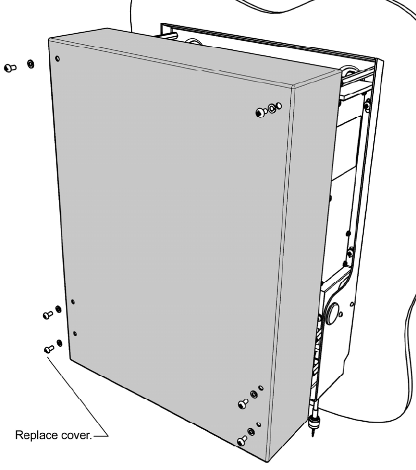
7.
Insert all cover screws loosely, then tighten to complete assembly.
External illumination
The transponder does not require external illumination during operation. However, some form of
illumination should be provided while installing or maintaining the transponder; this could be
portable or temporary.
89-041 Section 3 Issue 4 S3-7
UAIS VDU (Display)
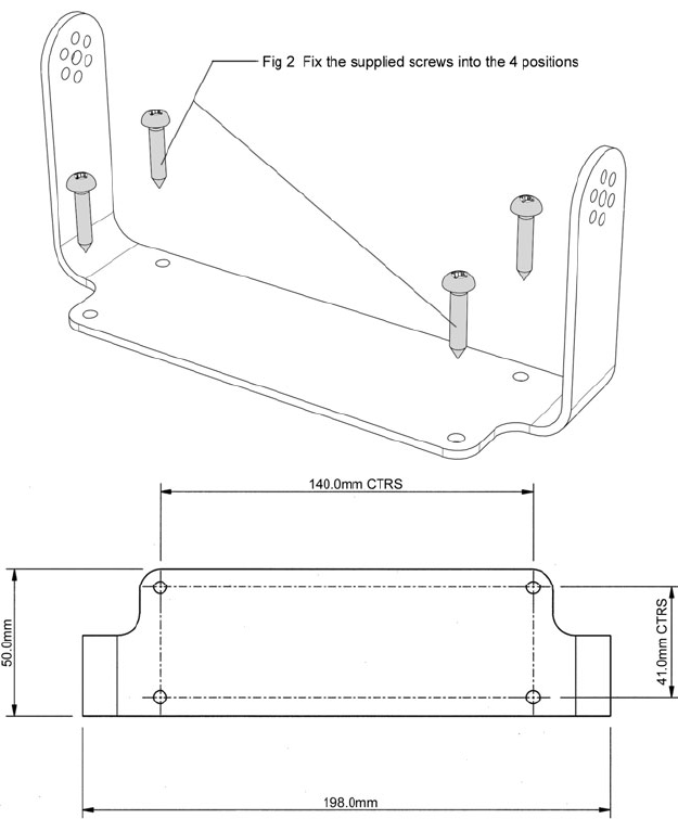
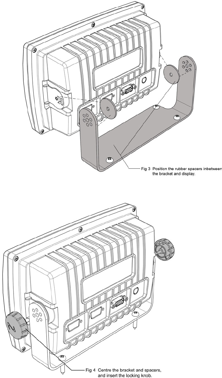
UAIS VDU trunnion assembly
The VDU can be either trunnion mounted or flush mounted.
1.
FRONT
Drilling drawing
Select hole size to suit method of
fixing mountings – clear or
tapped holes.
S3-8 89-041 Section 3 Issue 4
2.
3.
Mounted dimensions:
Height: 150mm
Width: 270mm
Depth: 120mm
(over connector)
89-041 Section 3 Issue 4 S3-9
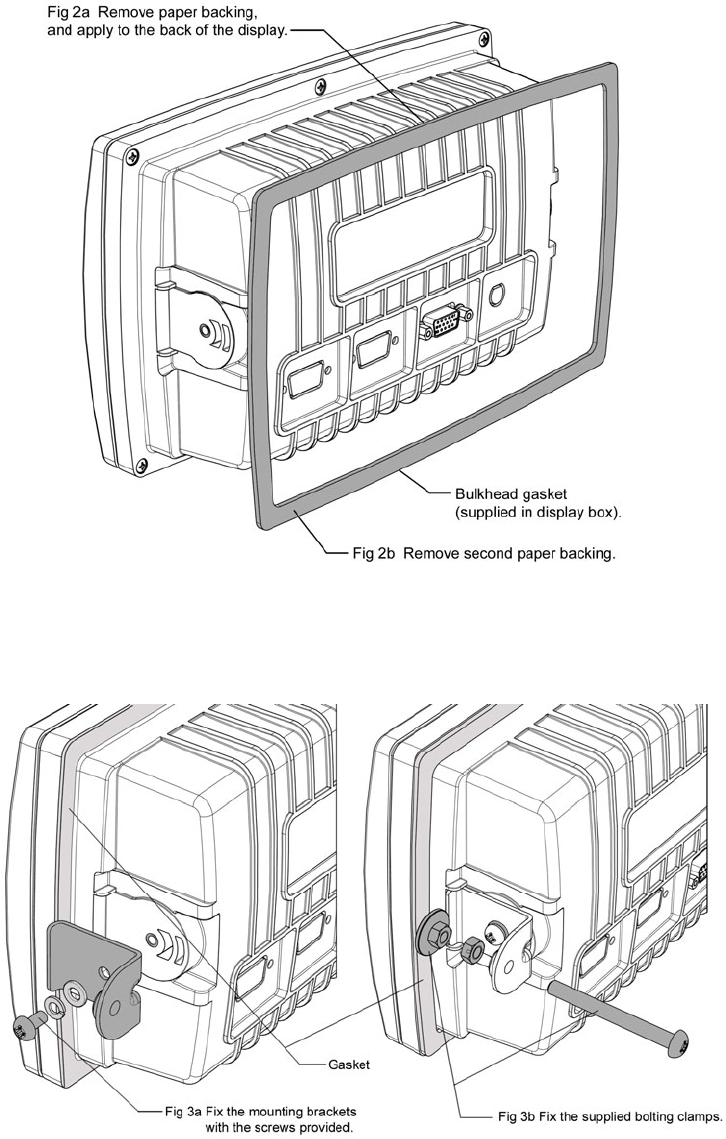
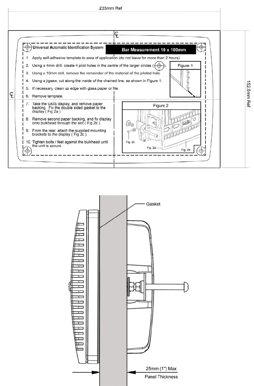
UAIS VDU flush mount assembly
A cutting template is supplied with the flush mounting kit. This template carries full fitting
instructions.
Template (reduced size)
1.
P2 89-041 Preface Issue 5
Contents
P - PREFACE............................................................................................................................................... 5
APPLICABILITY OF THIS MANUAL ................................................................................................................... 5
SECTION UPDATE RECORD........................................................................................................................... 5
INSTALLING THE UAIS TRANSPONDER SYSTEM SAFELY................................................................................ 6
RADIO FREQUENCY EXPOSURE WARNING .................................................................................................... 7
1 - INTRODUCTION..................................................................................................................................... 1
ABOUT THIS MANUAL ................................................................................................................................... 1
UAIS BUILDING BLOCKS .............................................................................................................................. 2
Options ................................................................................................................................................. 2
2 - UAIS TRANSPONDER SYSTEM ........................................................................................................... 1
SYSTEM OVERVIEW ..................................................................................................................................... 1
SYSTEM CONFIGURATION ............................................................................................................................ 2
3 - MECHANICAL MOUNTING OPTIONS AND GUIDELINES .................................................................. 1
LOCATION................................................................................................................................................... 1
UAIS TRANSPONDER UNIT .......................................................................................................................... 1
Transponder main dimensions ............................................................................................................. 1
UAIS VDU (DISPLAY)................................................................................................................................. 7
UAIS VDU trunnion assembly .............................................................................................................. 7
UAIS VDU flush mount assembly......................................................................................................... 9
Antenna units...................................................................................................................................... 11
Antenna mounting position................................................................................................................. 11
VHF antenna....................................................................................................................................... 11
GNSS antenna.................................................................................................................................... 11
Weld on plate mounting of the GNSS antenna .................................................................................. 13
Cable Preparation............................................................................................................................... 13
Mast assembly for GNSS antenna ..................................................................................................... 14
4 - ELECTRICAL CONNECTIONS.............................................................................................................. 1
INSTALLATION KIT (OPTIONAL)...................................................................................................................... 1
SIGNAL CABLE CONNECTIONS FOR UAIS TRANSPONDER............................................................................... 1
VHF AND GNSS (GPS) ANTENNA CABLE CONNECTIONS .............................................................................. 2
VHF antenna......................................................................................................................................... 2
GNSS (GPS) antenna........................................................................................................................... 3
SCREW TERMINAL BOARD ............................................................................................................................ 4
Fuse values .......................................................................................................................................... 4
Signal line termination .......................................................................................................................... 4
Test and program connections ............................................................................................................. 6
Power supply ........................................................................................................................................ 7
DISP port - Display VDU...................................................................................................................... 7
SEN 1, 2, 3 ports - Sensors.................................................................................................................. 8
SEN Ports necessary sentences:......................................................................................................... 8
Main and AUX high speed input/output ports....................................................................................... 9
MAIN port.............................................................................................................................................. 9
AUX port, Pilot plug .............................................................................................................................. 9
LRF port, Long Range Function ......................................................................................................... 10
RTCM port, Differential GNSS correction input/output port................................................................ 10
BIIT, Built In Integrity Test relay function............................................................................................ 10
COMPLETION OF INSTALLATION.................................................................................................................. 11
5 - SPECIFICATION..................................................................................................................................... 1
TECHNICAL INFORMATION............................................................................................................................ 2
INTERPRETATION OF IEC 61162-1 SENTENCES ........................................................................................... 3
6 - SERIAL INTERFACE COMMUNICATIONS PROTOCOLS................................................................... 1
SENSOR DATA INTERFACE............................................................................................................................ 1
MAIN AND AUX PORT RECEPTION AND TRANSMISSION OF UAIS DATA............................................................ 2
7 - WARRANTY REGISTRATION & ACCEPTANCE RECORD................................................................. 1
89-041 Preface Issue 5 P3
8 - PRE-INSTALLATION INSPECTION RECORD ..................................................................................... 1
9 - GLOSSARY ............................................................................................................................................ 1

89-041 Preface Issue 5 P5
P - Preface
Applicability of this manual
This manual is valid for all hardware and software issues of the equipment described, and is kept
current by update of the appropriate section(s).
When updates are posted, any incompatibility with earlier issues of hardware and/or software will
be highlighted here.
Section update record
Section Issue Date Comment
Preface 5 06/10/03
1 4 06/10/03
2 5 06/10/03
3 4 06/10/03
4 5 06/10/03
5 5 06/10/03
6 4 06/10/03
7 4 06/10/03
8 4 06/10/03
9 4 06/10/03
Disclaimer
Information contained in this manual is supplied in good faith, but is liable to change without notice.
McMurdo Limited disclaims any liability for consequences arising from omissions or inaccuracies in the
manuals and documentation provided with this product.
2003 McMurdo Ltd.
IMPORTANT: Please take time to read this manual carefully and to
understand its contents fully, so that you can install your Transceiver
correctly.
Once installed please read the Operation Manual fully to make sure you
understand how to use your new UAIS.

P6 89-041 Preface Issue 5
Installing the UAIS Transponder System Safely
Installation
WARNING: Do not connect the UAIS transponder system to a mains (line) AC electrical
supply, as an electric shock or fire hazard could result.
CAUTION: Do not connect the Transponder to a DC supply exceeding 32V or reverse the
supply polarity. Damage to the transceiver can result.
CAUTION: Do not bypass the built in fuses
CAUTION: The Transponder system is designed for operation in the temperature range
-15°C to +55°C. Do not install (or use) the transponder system in environments which exceed
this range.
CAUTION: The UAIS Transponder is not water-resistant. Consequently, the Transponder
must be installed in a dry place and must be protected from direct contact with water.
WARNING: Do not install the Transponder system in a position where;
a) the controls of your vessel may be obstructed.
b) it may obstruct your normal movement around your vessel.
c) it may cause bodily injury.
d) it cannot be easily accessed in an emergency.
Use
WARNING: Certain parts of the Transponder chassis can become hot during extended
periods of operation, notably the rear panel. Avoid touching these areas when the Transponder
is operating.
WARNING: Do not dismount the cover of the Transponder before the power is switched off.
Do not touch the antenna connections when the Transponder is operating and do not touch the
antenna whip (mast) or connecting cable when the Transponder is in operation, for RF
exposure and electrical safety reasons. Refer to Radio Frequency Exposure Warning.
WARNING: Unauthorised opening of the Transponder system will invalidate the warranty.
Maintenance
CAUTION: Avoid using chemical solvents to clean the Transponder system as some
solvents can damage the case material.
NOTE: Apart from the fuses located on the Screw Terminal Board, the Transponder system
contains no user serviceable parts. Return to your Service Agent for repair if replacing the fuses
fails to make the equipment servicable.
89-041 Preface Issue 5 P7
Radio Frequency Exposure Warning
To meet the current requirements for Radio Frequency Exposure it is necessary to install the
antenna mast correctly and operate the equipment according to the instructions.
The assumptions used in this assessment are: full transmit power is used, a good antenna is
used (assumed to be a 6dBi-gain omni-directional type).
Where no suitable structure exists to achieve a 3 metre vertical separation then the antenna
base must be mounted at least 1 metre above the head of any person within range and all
persons must stay outside the 3-metre safety radius.
Failure to adhere to these limits could expose persons within the 3 metre radius to RF radiation
in excess of the MPE / SAR limits.
WARNING: The antenna mast must be mounted at a
minimum distance (vertical separation) of 3 metres from the
head of any person standing on deck to meet international safety
directives on Maximum Permissible Exposure (MPE) / Specific
Absorption Rate (SAR).
WARNING: Do not transmit when persons are closer than 3
metres to the antenna. If any person (e.g. the operator) must be
closer, then a grounded RF shield should be interposed between
that person and the antenna.
Rules of Operation
Licensing
IMPORTANT: In most countries the operation of the UAIS
Transponder is a part of the radio regulations and therefore the
ship must possess a current VHF radio telephone licence which
lists the UAIS system, and the equipment must be registered
(Call Sign and MMSI number). Please contact the relevant
authority in your country for more information.
Refer to the UAIS Transponder Operation Manual for the full operating procedure.
Good Practice
The installer is expected to be familiar with IMO SN/Circ.227 Guidelines for the Installation of a
Shipborne Automatic Identification System, and to comply with these recommendations. The
document contains detailed information which supplements the instructions in this manual.
89-041 Section 1 Issue 4 S1- 1
1 - Introduction
It is recommended that the vessel should be surveyed prior to commencing any installation
work to determine the suitability of the existing on-board sensors. Section 8 of this Manual
contains a ‘Pre-Installation Inspection’ form to assist this process.
Installation of the UAIS Transponder has been designed to be as easy as possible and requires
few tools. However as the UAIS equipment forms a vital part of the ship’s navigational
equipment the installation must be performed with great care and with attention to detail.
The UAIS is considered part of the ship’s radio station and is surveyed together with the radio
installation. Surveys on Convention ships should be carried out in accordance with the rules laid
down in IMO Res. A 746(18) Survey Guidelines under the harmonised system of survey and
certification and Protocol of 1988 relating to the International Convention for the Safety of Life at
Sea 1974
For the AIS installation the following drawings shall be submitted for the survey:
• Antenna layout for the VHF and the GNSS antenna installation (prepared by the installer)
• AIS Arrangement drawing (included in this manual)
• Block diagram showing the interconnection to other units (included in this manual)
It is also necessary to complete an installation report, which shall be kept on board.
About this manual
This manual provides step-by-step guidance through the installation of the UAIS Transponder
system. Please read the manual carefully and make sure to follow the instructions.
In this manual only the installation of the UAIS stand-alone configuration will be described. If the
UAIS unit is to be connected to other display devices, refer to the manual for that display.
However the setup must always be performed with the display unit. Other display units will be
additional to the IMO required installation.
The procedures required for installation can be summarised:
1. Obtain a copy of the UAIS Pre-installation Inspection form; check that it is filled in with all the
data necessary for the installation. If the form has not been filled in, it is advisable to do it at
this stage, as this is a good way to make sure that all information is available for the
installation.
2. The available UAIS Transponder system building blocks are listed in section 1.2. Before
starting the installation ensure that everything needed for the installation is to hand.
3. Locate the places to install the different units. The templates and the drilling instructions are
provided in this manual.
4. Connect the units and the sensors as shown in this manual.
5. DO NOT SWITCH ON THE SYSTEM AT THIS STAGE. It is most important to read the
Operation Manual, which contains the commissioning information, before power is applied.
The Warranty Registration & Acceptance Record, Section 7 at the rear of this manual, must be
completed and signed when the system has been commissioned and accepted.
S1-2 89-041 Section 1 Issue 4
UAIS building blocks
VDU Transponder/display system 89-001-001
Transponder Only 89-051-001
VDU Display Only 89-052-001
GPS antenna assembly 89-021-001
Transponder 89-051-001
Transponder unit, packed with accessories:
2off PL 239 male plug for VHF antenna interface
2off TNC male for GNSS antenna interface
4off M6 x 40mm machine screws for bulkhead mounting
Installation manual
Optional: The Transponder unit can be delivered with a combined GLONAS/GPS receiver
VDU Display system (MKD) 89-052-001
Display unit, packed with accessories:
15 pin D-sub connector
Trunnion Mounting Bracket
4off No10 x 25mm self-tapping screws for mounting Trunnion Bracket
Flush mounting kit, including seal
Cutting template for flush mounting
Operation manual
GPS antenna assembly 89-021-001
GPS antenna unit, packed with accessories:
Mounting pole and mounting plate
2 off ‘U’-bolts for mounting pole and plate
Options
MT-1 Transponder 89-051-001
MT-1 VDU 89-052-001
MT-1 GPS antenna 89-021-001
VHF Antenna 89-020-001
S/S Stand-off bracket for VHF antenna 903-01
S/S Stand-off/Bulkhead bracket for VHF antenna 903-02
GPS Antenna Adapter 89-362
Gyro interface unit 89-028
AC/DC converter 89-029
Installation kit 89-038
Installation kit consists of:
2mm 2 core flex power cable 20m
RG214 Coax VHF antenna cable 30m
RG58 Coax GPS antenna cable 30m
0.5mm 4-twisted pair signal cable 60m
Cable tie 200
Cable marker 20
Crimp tool 1
Self amalgamating tape 2
89-041 Section 2 Issue 5 S2-1
2 - UAIS Transponder System
System overview
Universal Automatic Identification System (UAIS) is a maritime VHF-based transponder system
that provides high-speed automated communication from ship-to-ship and ship-to-shore, of
vessel, voyage and safety related data. This UAIS transponder and touch screen VDU display
system is the latest in state-of-the-art technology and is designed to meet the latest IMO
SOLAS requirements.
The UAIS transponder transmits the ship’s navigational data to other vessels, and also to shore
based VTS systems utilising various marine VHF channels. UAIS is primarily designed as a
ship-borne mobile station and consists of an integral GNSS engine used for timing, one VHF
transmitter, three VHF receivers and a computer unit. Interfacing to external GNSS used for
navigation, a VHF antenna, a gyrocompass, and an optional ECDIS or ARPA display system is
made easy by the built-in screw terminal board and the intuitive operating menu system on the
touch-screen display unit.
The VDU is designed to fulfil the minimum SOLAS requirements for system set-up and display
of the received target information (Minimum Keyboard and Display – MKD). However the large
touch screen LCD display also gives the user easy access to the menu system that controls the
system, and displays the received targets on a graphical, radar-like display.
Note: SOLAS requirements specify this equipment as Minimum Keyboard and Display (MKD).
Because all keyboard functions are implemented through the touch screen, it is more logical to
use the term VDU (Visual Display Unit); this terminology is used throughout this manual.
Compliance
This UAIS is designed to comply with current international standards and is approved in
accordance with the high standards of the European Marine Equipment Directive.
Compliances:
• MSC.74(69)
• ITU-R M.1371-1 1998
• EN 60945 4th edition, 2002; IEC 61993-2, 1st edition, 2001; IEC 61162-1, 2nd edition,
2000; IEC 61162-2, 1st edition 1998; IEC 61108
• ETS 300 113
S2-2 89-041 Section 2 Issue 5
System Configuration
The UAIS system can be installed either as part of an existing bridge installation, or as an
integrated part of a new bridge layout.
The main three configurations are:
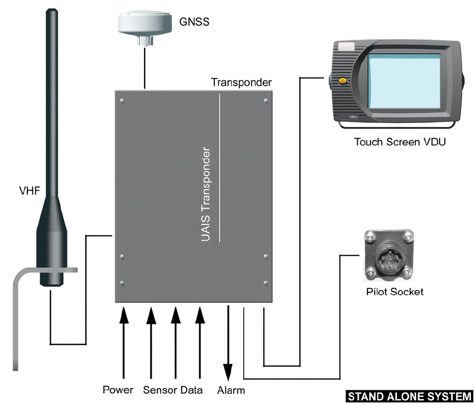
1 a stand-alone system
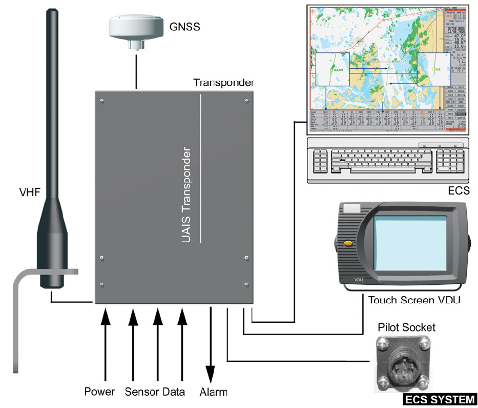
2 a system connected to an ECS
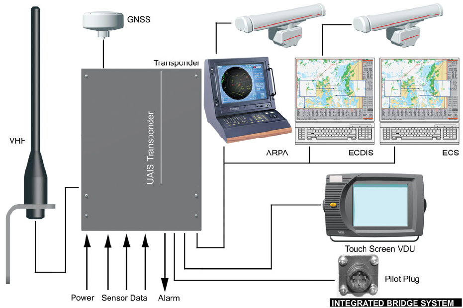
3 a system integrated into the bridge ARPA and ECDIS displays.
The stand-alone installation as illustrated below meets the SOLAS requirement for an AIS
installation. This installation uses the minimum display (VDU) as the main display for setting up
of own ship’s information and for display of the received navigational information.
The VDU provides the received navigational information in a graphical mode making it very
easy to achieve a situation overview.
89-041 Section 2 Issue 5 S2-3
In the Electronic Chart System (ECS) installation the stand-alone installation and an ECS
display have been integrated. This installation meets the SOLAS requirements for an AIS
installation. The VDU will mainly be used for input of own ship’s information and a compatible
ECS capable of decoding the NMEA standard implemented for UAIS will display the received
navigational information as AIS targets. This of course will greatly enhance the use of the
received target information, as the targets now will be displayed in the environment used for
navigation of the ship.
S2-4 89-041 Section 2 Issue 5
Integrating the AIS into an integrated bridge system (IBS) will display the received AIS target
information on a compatible ARPA or ECDIS giving the navigator the optimum use of the
received navigational information. The target information is then displayed in a way that makes
it easy for the navigator to see course, speed, rate and direction of turn of other approaching
vessels.
If the ARPA or ECDIS equipment is approved for use together with the AIS transponder the
VDU may not be required in the installation. However in many cases it will be necessary to
install the VDU to meet the SOLAS requirements. In these installations the VDU will be used to
load the transponder with own ship data and the ARPA or ECDIS equipment will be used to
display the received target information.
89-041 Section 2 Issue 5 S2-5
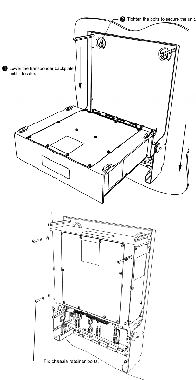
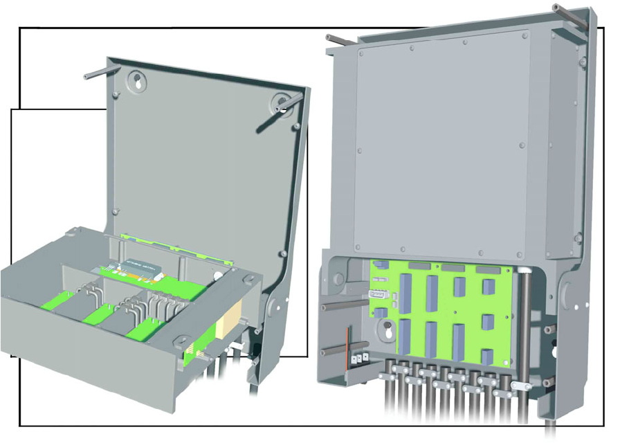
Transponder
The Transponder consists of a backplate to which a Screw Terminal Board, the Transponder
module and the cover are attached. The Transponder is connected to the Screw Terminal
Board via ribbon cables, making the Transponder easily to disconnect without the need to
disturb the interface cables. This feature makes it very easy to interchange Transponders,
keeping repair time to a minimum.
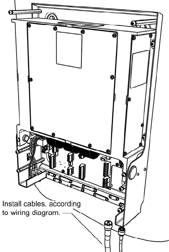
Installation of the Transponder is made as easy as possible, as interface cables can be
connected directly to the built in Screw Terminal Board. The keyholes in the back plate make it
simple to attach the Transponder to a bulkhead.

S2-6 89-041 Section 2 Issue 5
Display
The display unit (VDU) can be tabletop or bulkhead mounted. The necessary brackets for
mounting are included and are very easy to use. A single cable connects the VDU to the
Transponder unit.
Note: SOLAS requirements specify this equipment as Minimum Keyboard and Display (MKD).
Because all keyboard functions are implemented through the touch screen, it is more logical to
use the term VDU (Visual Display Unit); this terminology is used throughout this manual.
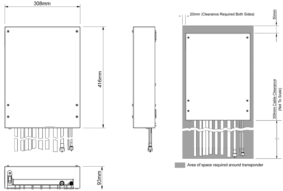
89-041 Section 3 Issue 4 S3-1
3 - Mechanical Mounting options and guidelines
Location
The Transponder unit may be mounted in any convenient location. However, it is classed as
protected equipment and thus should be located inside in a dry environment. Normally the
transponder is located in the Radio Room. The transponder compass safe distance is 2.3m.
The VDU (MKD) should be available to the mariner at the position from which the ship is
normally operated. The VDU compass safe distance is 0.6m.
The Pilot Plug should be installed on the bridge near the pilot’s operating position.
Special considerations apply to antennas. These are outlined in the appropriate section; for
detailed advice, see the IMO Guidelines.
UAIS Transponder unit
The Transponder is attached to the bulkhead by four M6 screws. Keyhole slots in the
Transponder allow the screws to be inserted in the bulkhead, then the Transponder to be
mounted on the screws and to be self-supporting while the screws are tightened.
It is recommended to leave at least 300 mm free space below the Transponder to allow for
connection cables, as shown below right.
Transponder main dimensions
Note: When open, the transponder
chassis projects 350mm from the
mounting surface
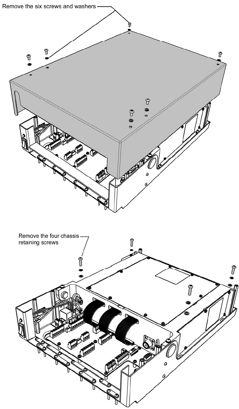
S3-2 89-041 Section 3 Issue 4
1.
2.
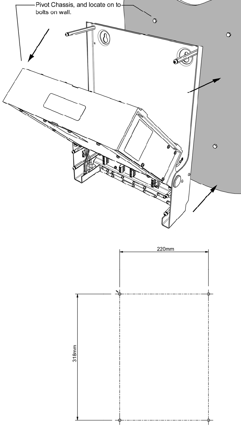
89-041 Section 3 Issue 4 S3-3
3.
Drilling drawing
Select hole size to suit method of
fixing mountings – clear or tapped
holes.