Orolia MT-1 McMurdo/Transas MT-1 User Manual Installation Manual 89 041N
Orolia Ltd McMurdo/Transas MT-1 Installation Manual 89 041N
Orolia >
Contents
- 1. Installation Manual 89 041N
- 2. Operating Manual Section 1
- 3. Operation Manual Section 2
- 4. Operation Manual Section 3
Installation Manual 89 041N
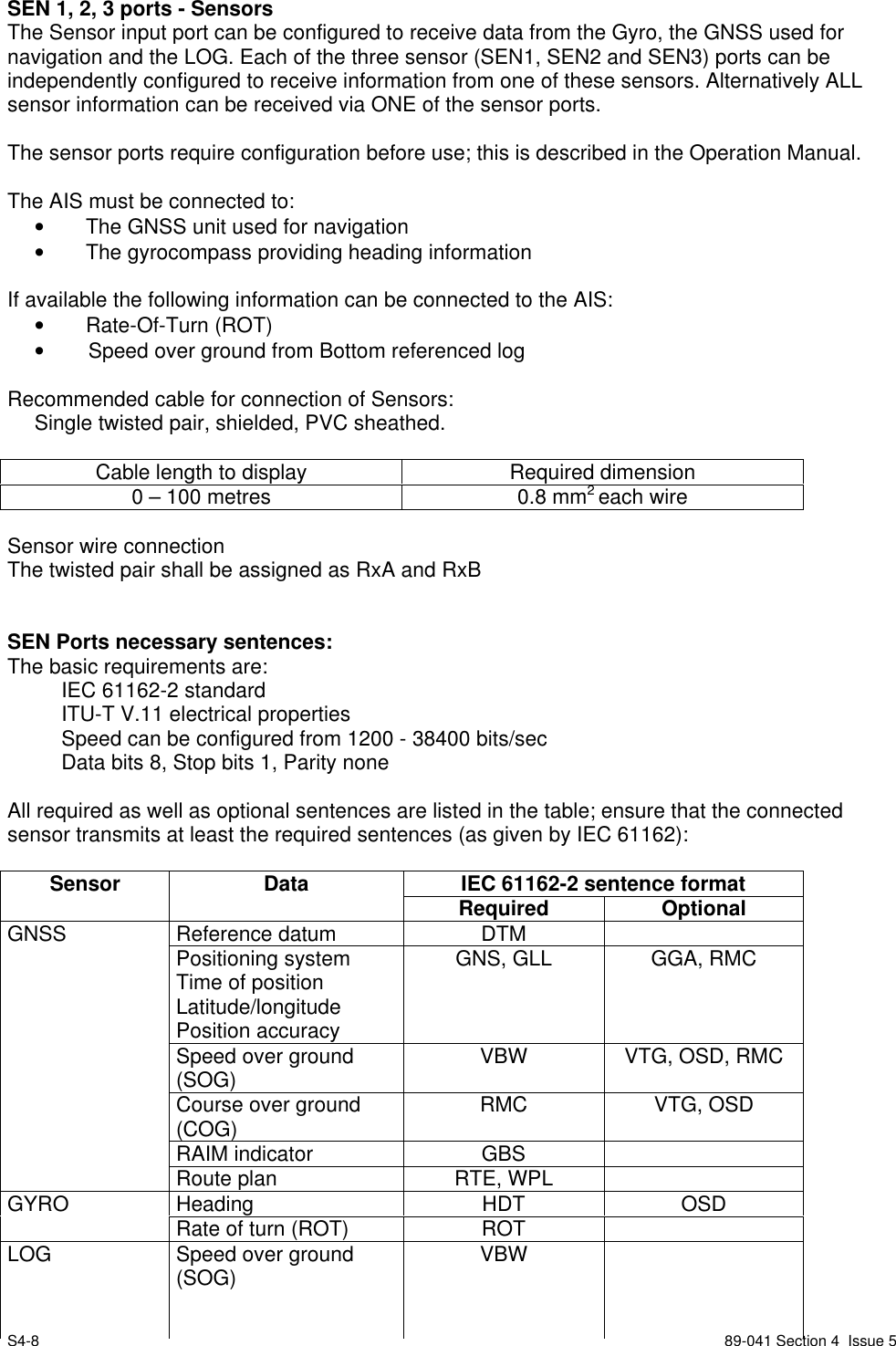
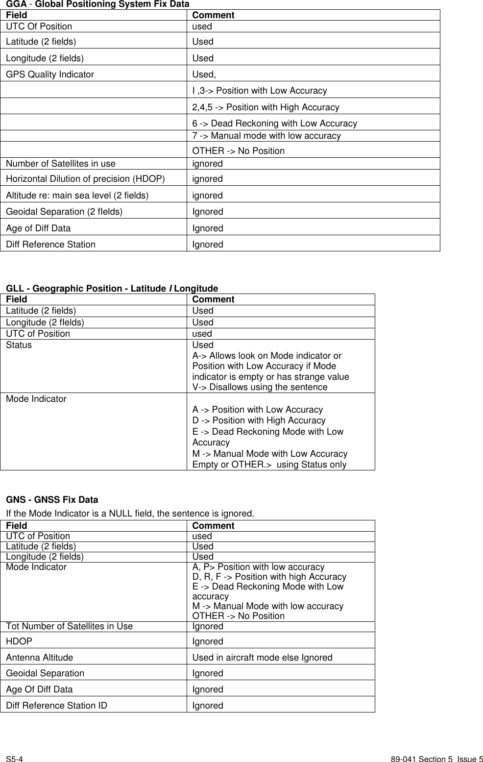
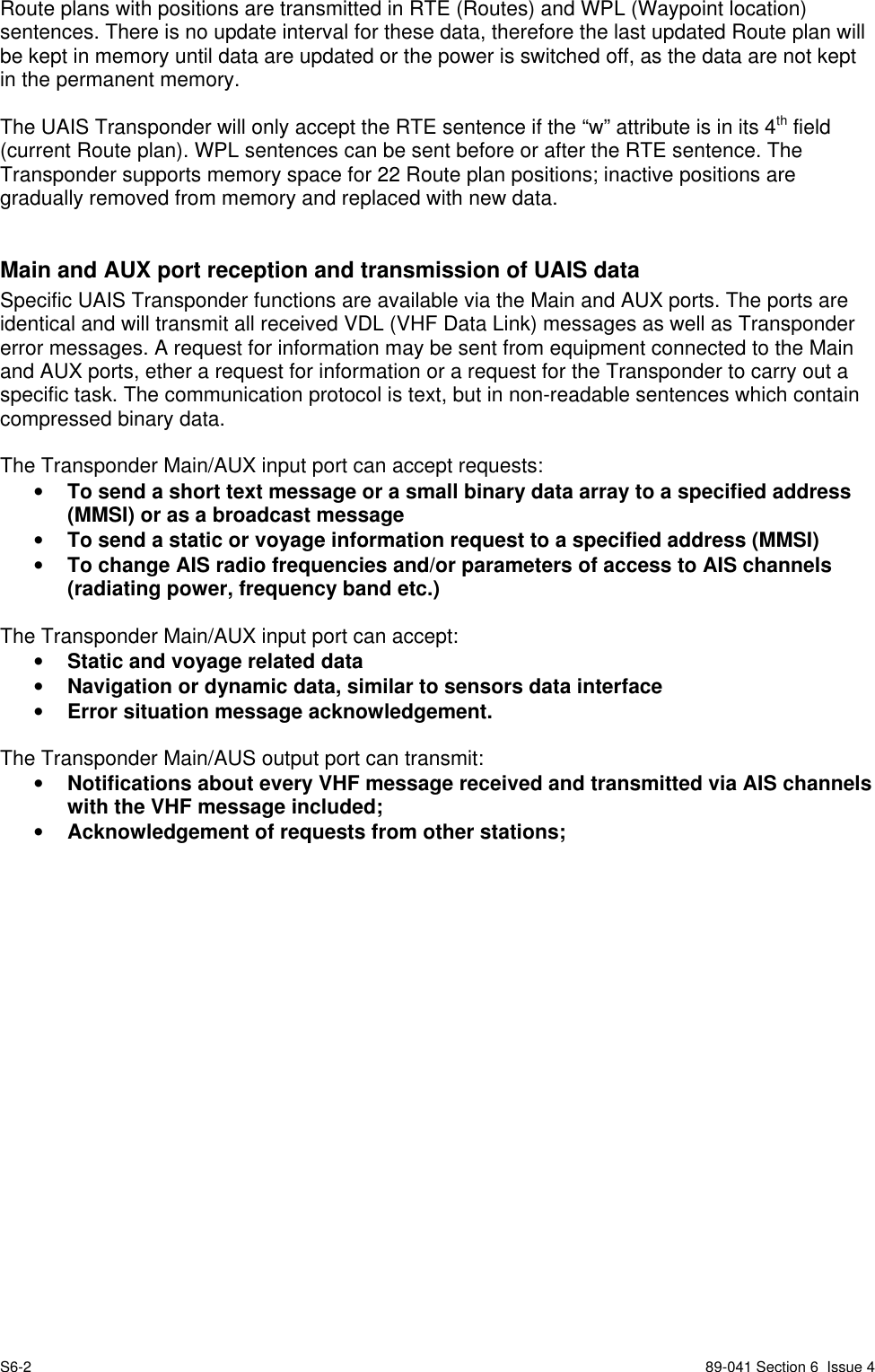
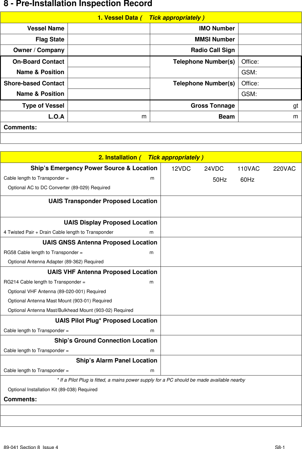
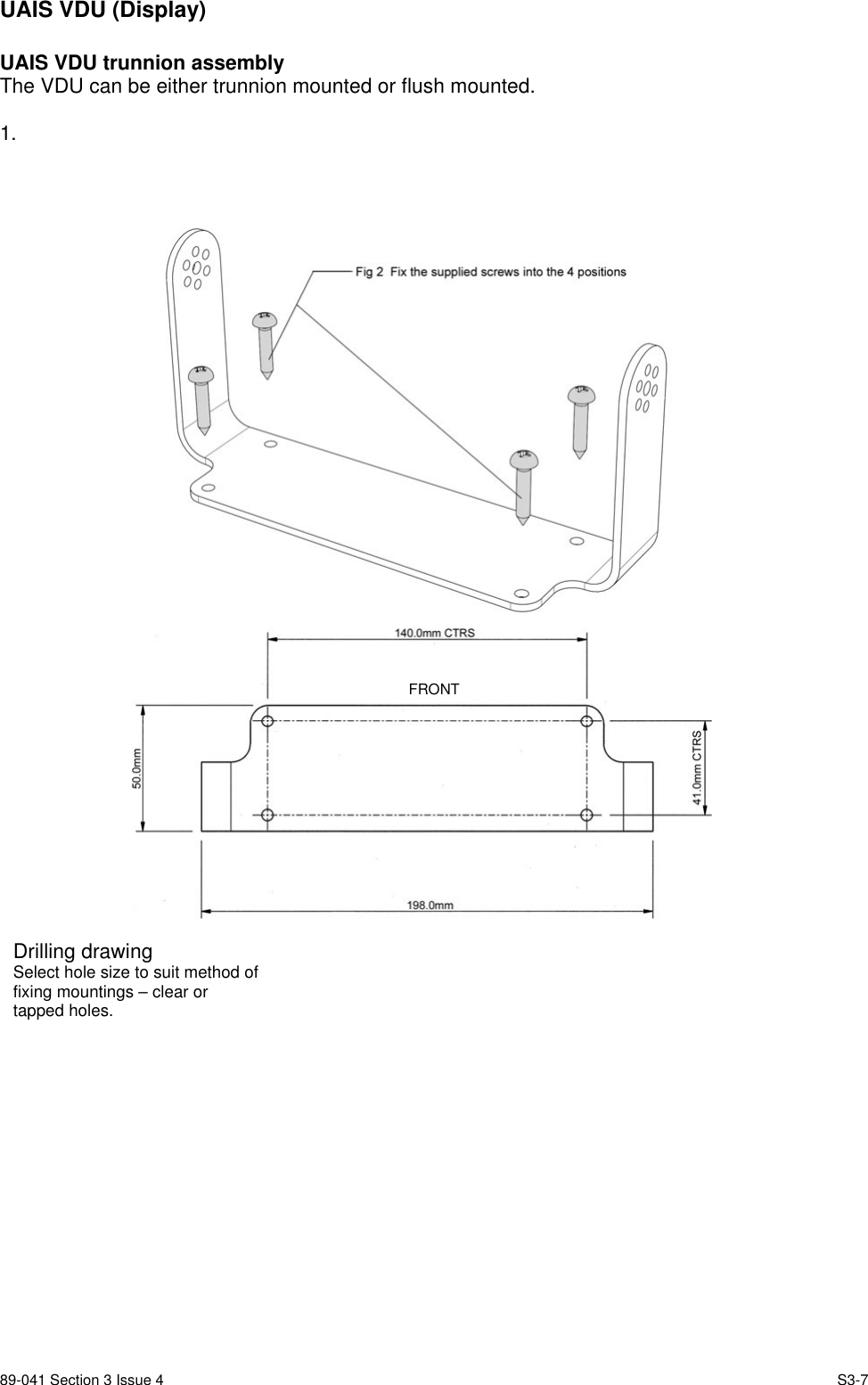
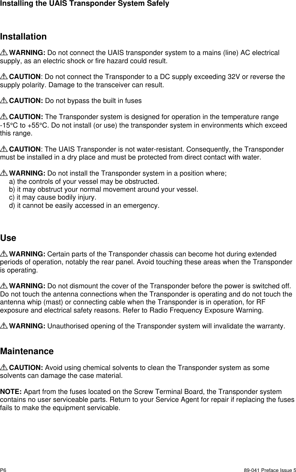
![S5-8 89-041 Section 5 Issue 5BBM - Broadcast Binary MessageField CommentTotal Number of Sentences Used if in interval 1 ..9, otherwise rejectedSentence Number Used if In interval 1…[total number of sentences],otherwise rejected.Sequential Message Identifier Used If in interval 0..9, otherwise rejectedAIS Channel UsedMessage Id Used if 8 or 14Encapsulated Data UsedNumber of filled bits UsedSSD - Ship Static DataField CommentCall Sign Used, may be NULLName Used, may be NULLPos Ref A Used to change position reference for the position sourcein use. May be NULL.Pos Ref B Used to change position reference for the position sourcein use. May be NULL.Pos Ref C Used to change position reference for the position sourcein use. May be NULL.Pos Ref D Used to change position reference for the position sourceIn use. May be NULL.DTE UsedSource Identifier IgnoredVSD - Voyage Static DataField CommentType Of Ship And Cargo UsedMaximum Present Draught UsedPersons On-Board UsedDestination UsedEst. UTC of arrival UsedEst. Day of arrival UsedEst. Month of arrival UsedNavigational Status UsedRegional Application Flags Ignored](https://usermanual.wiki/Orolia/MT-1.Installation-Manual-89-041N/User-Guide-390818-Page-15.png)
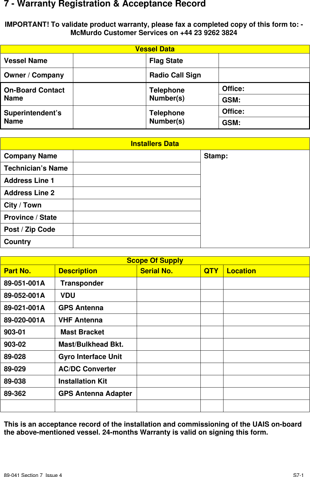
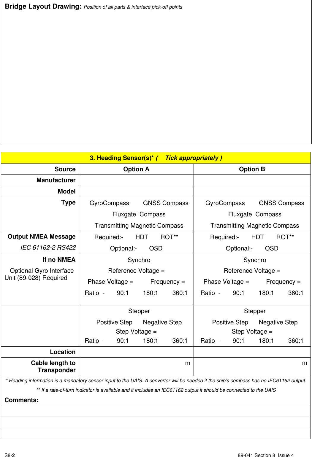
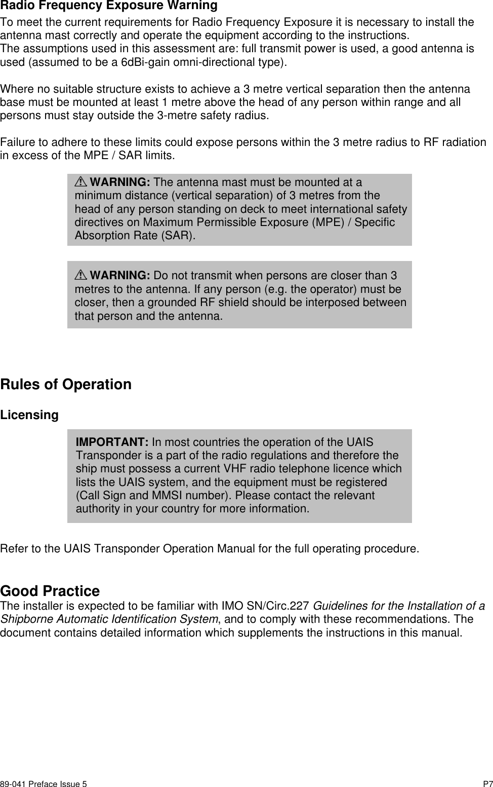
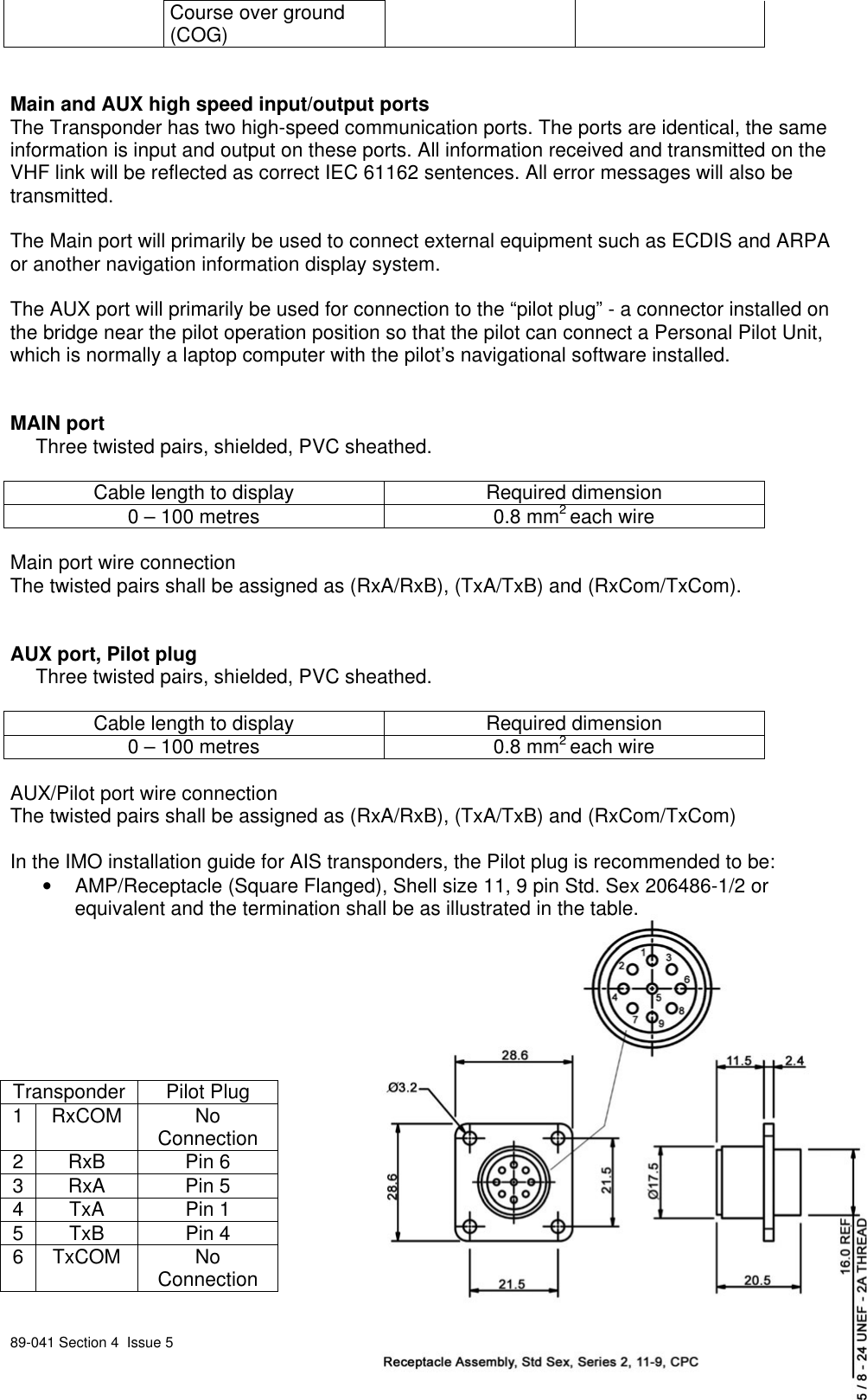
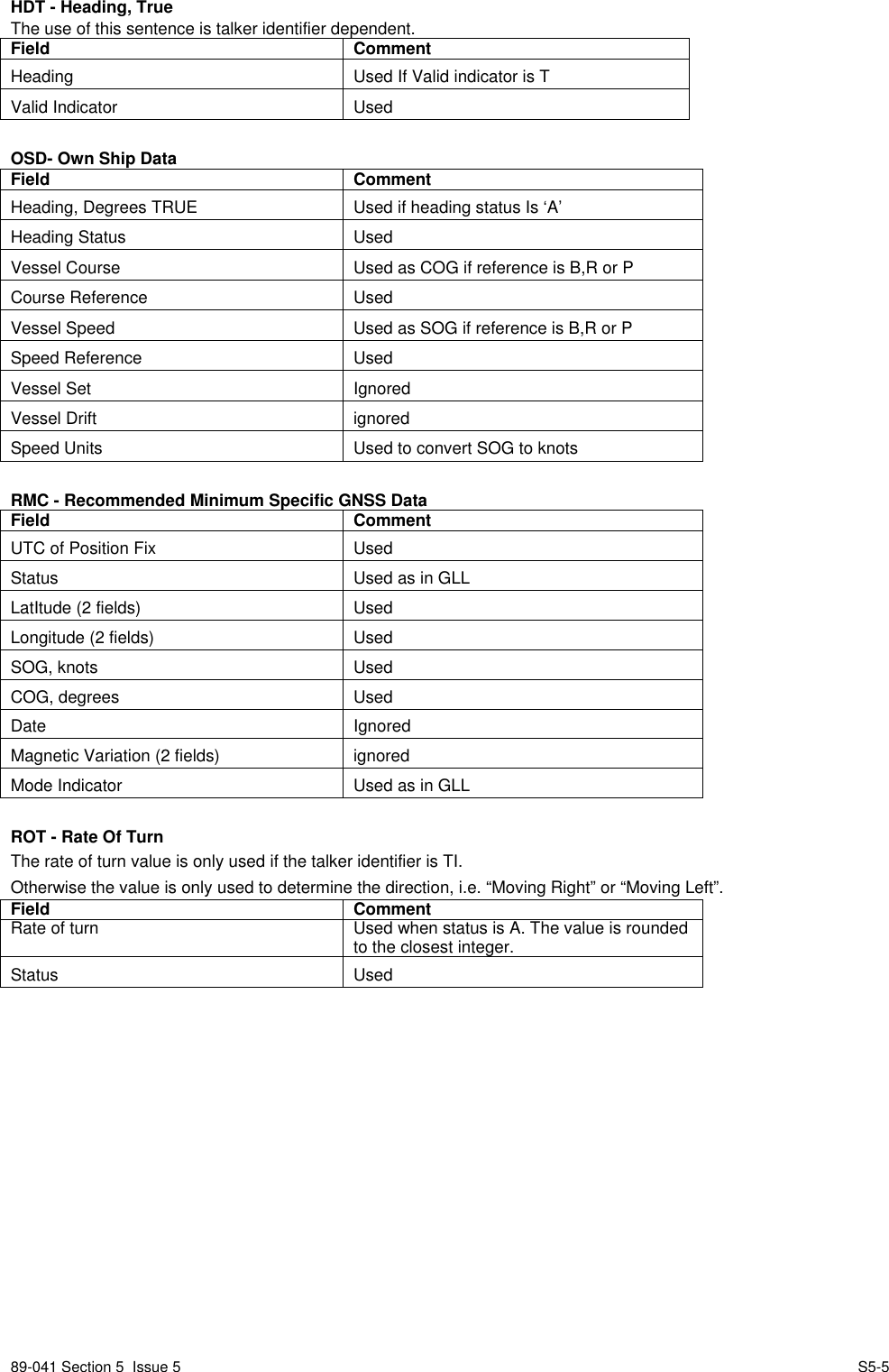
![89-041 Section 6 Issue 4 S6-16 - Serial interface communications protocolsAs previously stated, the Transponder has seven RS-422 interfaces which are all available onthe Screw Terminal board:• 3 sensor data input ports SEN1, SEN2 and SEN3• 2 Bi-directional input/output ports MAIN and AUX/Pilot• 1 Bi-directional input/output port RTCM• 1 Bi-directional input/output port LR (Long Range)Sensor data interfaceThe Sensor data input ports receive navigational data in NMEA–0183 format from theconnected sensors. The connected sensors can be a GNSS unit used for navigation, agyrocompass and a bottom track log. These data are processed in the UAIS unit andtransmitted as dynamic data. The data received by other stations over the VHF link form animage of the sensor data. It is therefore vital that the sensor data are correct and that the port iscorrectly configured.The sensor ports of the UAIS Transponder understand the following IEC 61162 sentences. Thepriority order of listing is left to right:Latitude & Longitude: GNS, RMC, GGA, GLLSpeed Over Ground: VBW, RMC, VTG, OSDCourse Over Ground: RMC, VBW, VTG, OSDHeading: HDT, OSDRate Of Turn: ROT, calculated from heading (HDT, OSD).Navigational data must be received via the sensor ports within certain intervals; the maximumintervals are listed in the table below. If NMEA sentences containing identical information arriveat the sensor input ports, the UAIS Transponder will choose the information with the highestpriority level.The built-in GNSS unit will under normal conditions only be used for TDMA slot timing. Howeverif no data are received from the external sensors, the built-in GNSS unit can be set to take overautomatically and supply navigational information for the VHF data link transmission. Thechangeover between internal GNSS information use and external sensor information usehappens automatically, information received from the external sensors has priority and willalways be used when available.List of messages received from sensorsData type Max updateinterval [s] NMEA application Default parameter valueDate 3 RMC Year 2000, month. 0, day 0UTC 3 GNS, RMC, GGA,GLL 24:60:60Lat, Lon 3 GNS, RMC, GGA,GLL 91°00′00″ nl, 181°00′00″ wlDatum 30 DTM Not definedSOG,COG 3 RMC, VBW, OSD 102.3, 360°Altitude 3 GNS 4095Heading 10 HDT 511Turn rate 10 ROT -128RAIM 10 GBS Ok](https://usermanual.wiki/Orolia/MT-1.Installation-Manual-89-041N/User-Guide-390818-Page-16.png)