Orolia MT-1 McMurdo/Transas MT-1 User Manual Operation Manual Section 3

Orolia Ltd McMurdo/Transas MT-1 Operation Manual Section 3

Operation Manual Section 3
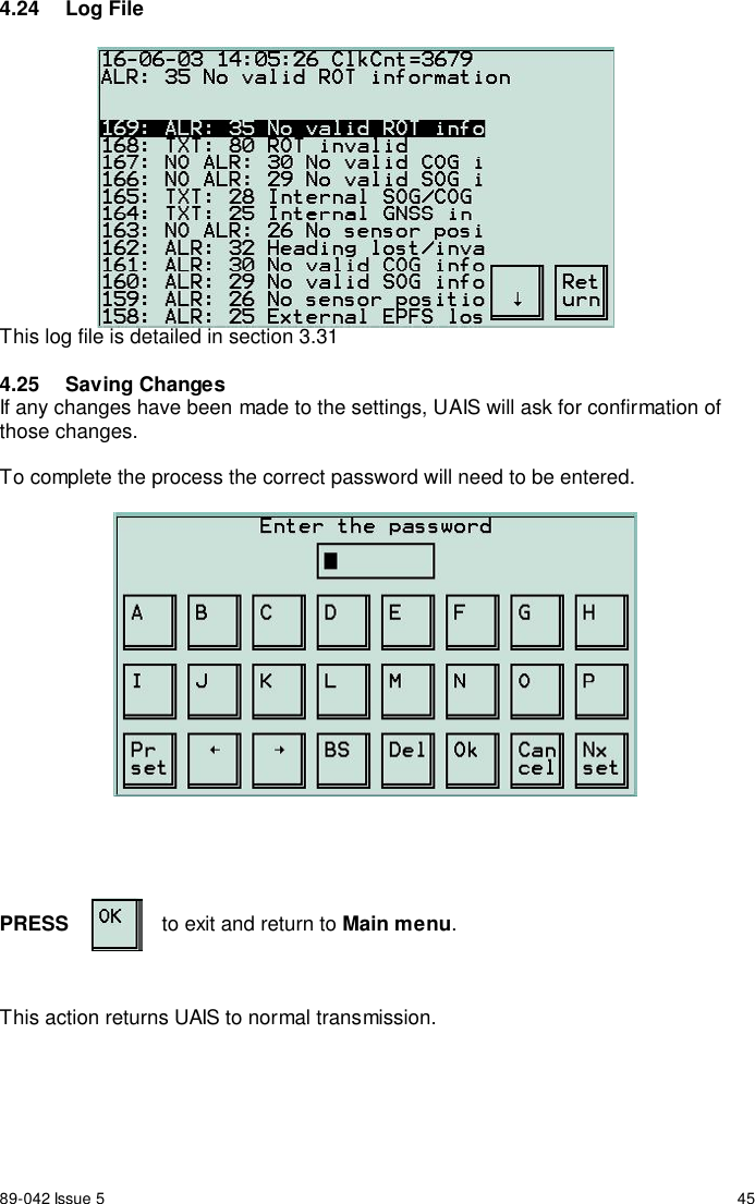
89-042 Issue 5 454.24 Log FileThis log file is detailed in section 3.314.25 Saving ChangesIf any changes have been made to the settings, UAIS will ask for confirmation ofthose changes.To complete the process the correct password will need to be entered.PRESS to exit and return to Main menu.This action returns UAIS to normal transmission.
89-042 Issue 5 475  Maintenance and Servicing5.1 Preventative MaintenanceThe UAIS transponder system is an essential part of the ship’s navigation systemand is a vital component for the safety of the ship and its crew. It is therefore veryimportant to maintain the system and its installation to a very high standard. Thedesign of the UAIS transponder ensures that maintenance can be kept to aminimum, however it is good practice to perform a performance check at least onceevery week.5.2 VDU Touch-ScreenTo optimise performance of the touch-screen VDU and cabinet, ensure they arekept clean and grease-free. Use a clean damp cloth, or for heavier deposits use aclean, damp cloth and a mild solution of dish washing detergent and water. Do notuse any spirit or alcohol based solvents, gasoline or oils.5.3 Electrical ConnectionsPeriodically check the electrical connections; ensure that no cables are frayed orworn, and that all connections are tight and sound.5.4  Repair and ServiceWith the exception of the fuses located on the Screw Terminal Board, there are nouser serviceable parts. Changing fuses is described in Section 6 – Troubleshooting.Removal of the inspection plates other than by an Authorised Service Technicianwill void warranty. If having followed the Troubleshooting Guide (Section 6) UAIS isstill inoperable, please call your local Service Centre.5.5 Spare PartsUse only manufacturers genuine spare parts. No liability can be accepted forequipment failure due to incorrect replacement parts being used.5.6  World-wide Sales and ServiceFor a complete list of worldwide sales and service agents, please contact yourproduct supplier.
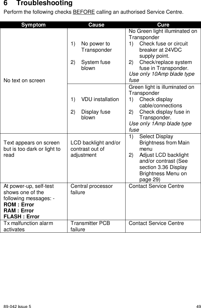
89-042 Issue 5 496 TroubleshootingPerform the following checks BEFORE calling an authorised Service Centre.Symptom Cause Cure1)  No power toTransponder2) System fuseblownNo Green light illuminated onTransponder1)  Check fuse or circuitbreaker at 24VDCsupply point.2) Check/replace systemfuse in Transponder.Use only 10Amp blade typefuseNo text on screen1) VDU installation2) Display fuseblownGreen light is illuminated onTransponder1) Check displaycable/connections2)  Check display fuse inTransponder.Use only 1Amp blade typefuseText appears on screenbut is too dark or light toreadLCD backlight and/orcontrast out ofadjustment1) Select DisplayBrightness from Mainmenu2)  Adjust LCD backlightand/or contrast (Seesection 3.36 DisplayBrightness Menu onpage 29)At power-up, self-testshows one of thefollowing messages: -ROM : ErrorRAM : ErrorFLASH : ErrorCentral processorfailure Contact Service CentreTx malfunction alarmactivates Transmitter PCBfailure Contact Service Centre
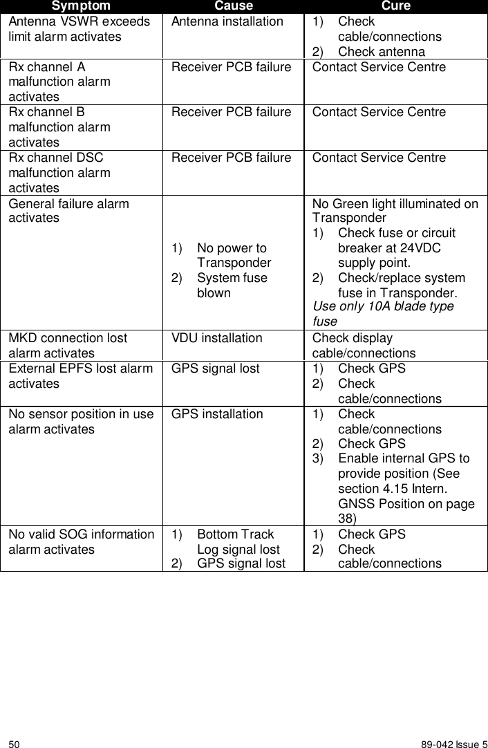
50 89-042 Issue 5Symptom Cause CureAntenna VSWR exceedslimit alarm activates Antenna installation 1)  Checkcable/connections2) Check antennaRx channel Amalfunction alarmactivatesReceiver PCB failure Contact Service CentreRx channel Bmalfunction alarmactivatesReceiver PCB failure Contact Service CentreRx channel DSCmalfunction alarmactivatesReceiver PCB failure Contact Service CentreGeneral failure alarmactivates1)  No power toTransponder2) System fuseblownNo Green light illuminated onTransponder1)  Check fuse or circuitbreaker at 24VDCsupply point.2) Check/replace systemfuse in Transponder.Use only 10A blade typefuseMKD connection lostalarm activates VDU installation Check displaycable/connectionsExternal EPFS lost alarmactivates GPS signal lost 1)  Check GPS2) Checkcable/connectionsNo sensor position in usealarm activates GPS installation 1)  Checkcable/connections2) Check GPS3)  Enable internal GPS toprovide position (Seesection 4.15 Intern.GNSS Position on page38)No valid SOG informationalarm activates 1) Bottom TrackLog signal lost2)  GPS signal lost1) Check GPS2) Checkcable/connections
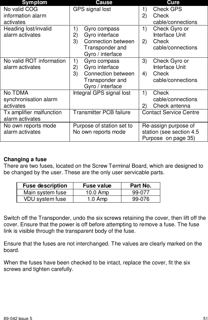
89-042 Issue 5 51Symptom Cause CureNo valid COGinformation alarmactivatesGPS signal lost 1)  Check GPS2) Checkcable/connectionsHeading lost/invalidalarm activates 1) Gyro compass2) Gyro interface3) Connection betweenTransponder andGyro / interface1)  Check Gyro orInterface Unit2) Checkcable/connectionsNo valid ROT informationalarm activates 1) Gyro compass2) Gyro interface3) Connection betweenTransponder andGyro / interface3)  Check Gyro orInterface Unit4) Checkcable/connectionsNo TDMAsynchronisation alarmactivatesIntegral GPS signal lost 1)  Checkcable/connections2) Check antennaTx amplifier malfunctionalarm activates Transmitter PCB failure Contact Service CentreNo own reports modealarm activates Purpose of station set toNo own reports mode Re-assign purpose ofstation (see section 4.5Purpose  on page 35)Changing a fuseThere are two fuses, located on the Screw Terminal Board, which are designed tobe changed by the user. These are the only user servicable parts.Fuse description Fuse value Part No.Main system fuse 10.0 Amp 99-077VDU system fuse 1.0 Amp 99-076Switch off the Transponder, undo the six screws retaining the cover, then lift off thecover. Ensure that the power is off before attempting to remove a fuse. The fuselink is visible through the transparent body of the fuse.Ensure that the fuses are not interchanged. The values are clearly marked on theboard.When the fuses have been checked to be intact, replace the cover, fit the sixscrews and tighten carefully.
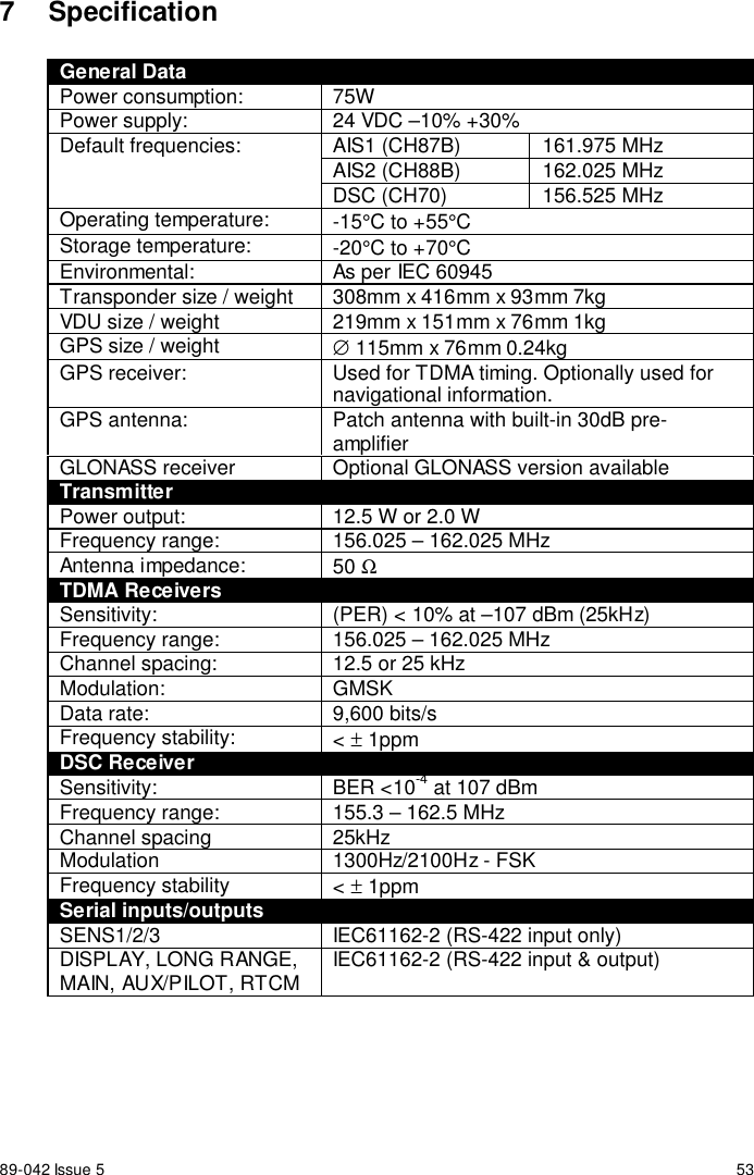
89-042 Issue 5 537 SpecificationGeneral DataPower consumption: 75WPower supply: 24 VDC –10% +30%AIS1 (CH87B) 161.975 MHzAIS2 (CH88B) 162.025 MHzDefault frequencies:DSC (CH70) 156.525 MHzOperating temperature: -15°C to +55°CStorage temperature: -20°C to +70°CEnvironmental: As per IEC 60945Transponder size / weight 308mm x 416mm x 93mm 7kgVDU size / weight 219mm x 151mm x 76mm 1kgGPS size / weight ∅ 115mm x 76mm 0.24kgGPS receiver: Used for TDMA timing. Optionally used fornavigational information.GPS antenna: Patch antenna with built-in 30dB pre-amplifierGLONASS receiver Optional GLONASS version availableTransmitterPower output: 12.5 W or 2.0 WFrequency range: 156.025 – 162.025 MHzAntenna impedance: 50 ΩTDMA ReceiversSensitivity: (PER) < 10% at –107 dBm (25kHz)Frequency range: 156.025 – 162.025 MHzChannel spacing: 12.5 or 25 kHzModulation: GMSKData rate: 9,600 bits/sFrequency stability: < ± 1ppmDSC ReceiverSensitivity: BER <10-4 at 107 dBmFrequency range: 155.3 – 162.5 MHzChannel spacing 25kHzModulation 1300Hz/2100Hz - FSKFrequency stability < ± 1ppmSerial inputs/outputsSENS1/2/3 IEC61162-2 (RS-422 input only)DISPLAY, LONG RANGE,MAIN, AUX/PILOT, RTCM IEC61162-2 (RS-422 input & output)
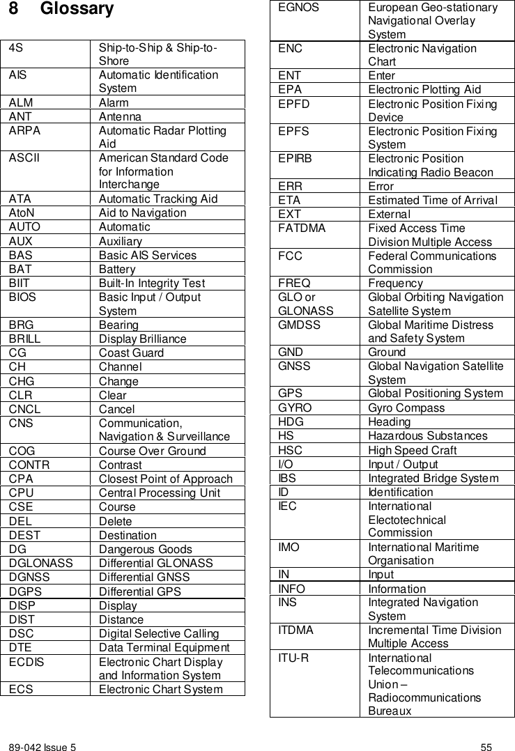
89-042 Issue 5 558 Glossary4S Ship-to-Ship & Ship-to-ShoreAIS Automatic IdentificationSystemALM AlarmANT AntennaARPA Automatic Radar PlottingAidASCII American Standard Codefor InformationInterchangeATA Automatic Tracking AidAtoN Aid to NavigationAUTO AutomaticAUX AuxiliaryBAS Basic AIS ServicesBAT BatteryBIIT Built-In Integrity TestBIOS Basic Input / OutputSystemBRG BearingBRILL Display BrillianceCG Coast GuardCH ChannelCHG ChangeCLR ClearCNCL CancelCNS Communication,Navigation & SurveillanceCOG Course Over GroundCONTR ContrastCPA Closest Point of ApproachCPU Central Processing UnitCSE CourseDEL DeleteDEST DestinationDG Dangerous GoodsDGLONASS Differential GLONASSDGNSS Differential GNSSDGPS Differential GPSDISP DisplayDIST DistanceDSC Digital Selective CallingDTE Data Terminal EquipmentECDIS Electronic Chart Displayand Information SystemECS Electronic Chart SystemEGNOS European Geo-stationaryNavigational OverlaySystemENC Electronic NavigationChartENT EnterEPA Electronic Plotting AidEPFD Electronic Position FixingDeviceEPFS Electronic Position FixingSystemEPIRB Electronic PositionIndicating Radio BeaconERR ErrorETA Estimated Time of ArrivalEXT ExternalFATDMA Fixed Access TimeDivision Multiple AccessFCC Federal CommunicationsCommissionFREQ FrequencyGLO orGLONASS Global Orbiting NavigationSatellite SystemGMDSS Global Maritime Distressand Safety SystemGND GroundGNSS Global Navigation SatelliteSystemGPS Global Positioning SystemGYRO Gyro CompassHDG HeadingHS Hazardous SubstancesHSC High Speed CraftI/O Input / OutputIBS Integrated Bridge SystemID IdentificationIEC InternationalElectotechnicalCommissionIMO International MaritimeOrganisationIN InputINFO InformationINS Integrated NavigationSystemITDMA Incremental Time DivisionMultiple AccessITU-R InternationalTelecommunicationsUnion –RadiocommunicationsBureaux
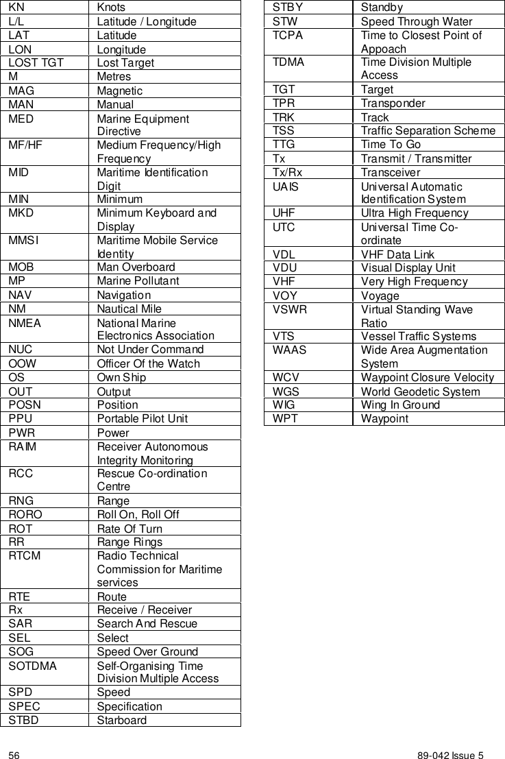
89-042 Issue 556KN KnotsL/L Latitude / LongitudeLAT LatitudeLON LongitudeLOST TGT Lost TargetMMetresMAG MagneticMAN ManualMED Marine EquipmentDirectiveMF/HF Medium Frequency/HighFrequencyMID Maritime IdentificationDigitMIN MinimumMKD Minimum Keyboard andDisplayMMSI Maritime Mobile ServiceIde nti tyMOB Man OverboardMP Marine PollutantNAV NavigationNM Nautical MileNMEA National MarineElectronics AssociationNUC Not Under CommandOOW Officer Of the WatchOS Own ShipOUT OutputPOSN PositionPPU Portable Pilot UnitPWR PowerRAIM Receiver AutonomousIntegrity MonitoringRCC Rescue Co-ordinationCentreRNG RangeRORO Roll On, Roll OffROT Rate Of TurnRR Range Ri ngsRTCM Radio TechnicalCommission for MaritimeservicesRTE RouteRx Receive / ReceiverSAR Search And RescueSEL SelectSOG Speed Over GroundSOTDMA Self-Organising TimeDivision Multiple AccessSPD SpeedSPEC SpecificationSTBD StarboardSTBY StandbySTW Speed Through WaterTCPA Time to Closest Point ofAppoachTDMA Time Division MultipleAccessTGT TargetTPR TransponderTRK TrackTSS Traffic Separation SchemeTTG Time To GoTx Transmit / TransmitterTx/Rx TransceiverUAIS Universal AutomaticIdentification SystemUHF Ultra High FrequencyUTC Universal Time Co-ordinateVDL VHF Data LinkVDU Visual Display UnitVHF Very High FrequencyVOY VoyageVSWR Virtual Standing WaveRatioVTS Vessel Traffic SystemsWAAS Wide Area AugmentationSystemWCV Waypoint Closure VelocityWGS World Geodetic SystemWIG Wing In GroundWPT Waypoint
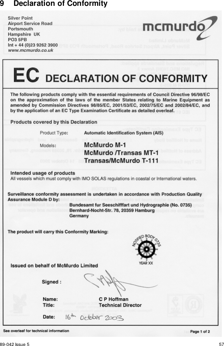
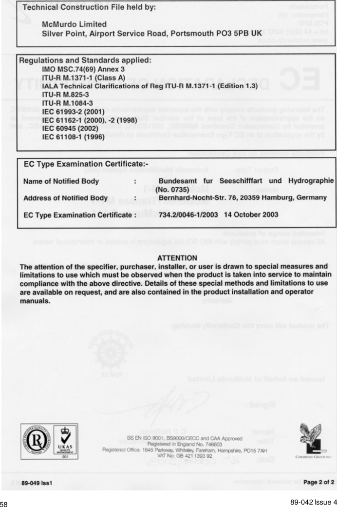
89-042 Issue 5 579  Declaration of Conformity
89-042 Issue 458

Navigation menu