Orolia MT-1 McMurdo/Transas MT-1 User Manual Operation Manual Section 2
Orolia Ltd McMurdo/Transas MT-1 Operation Manual Section 2
Orolia >
Contents
- 1. Installation Manual 89 041N
- 2. Operating Manual Section 1
- 3. Operation Manual Section 2
- 4. Operation Manual Section 3
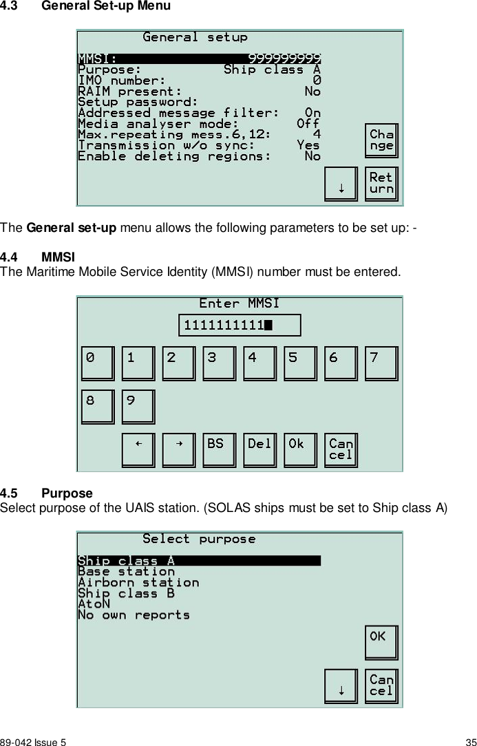
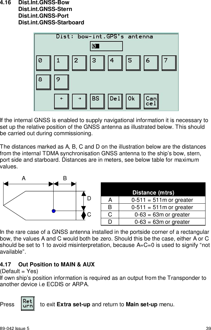
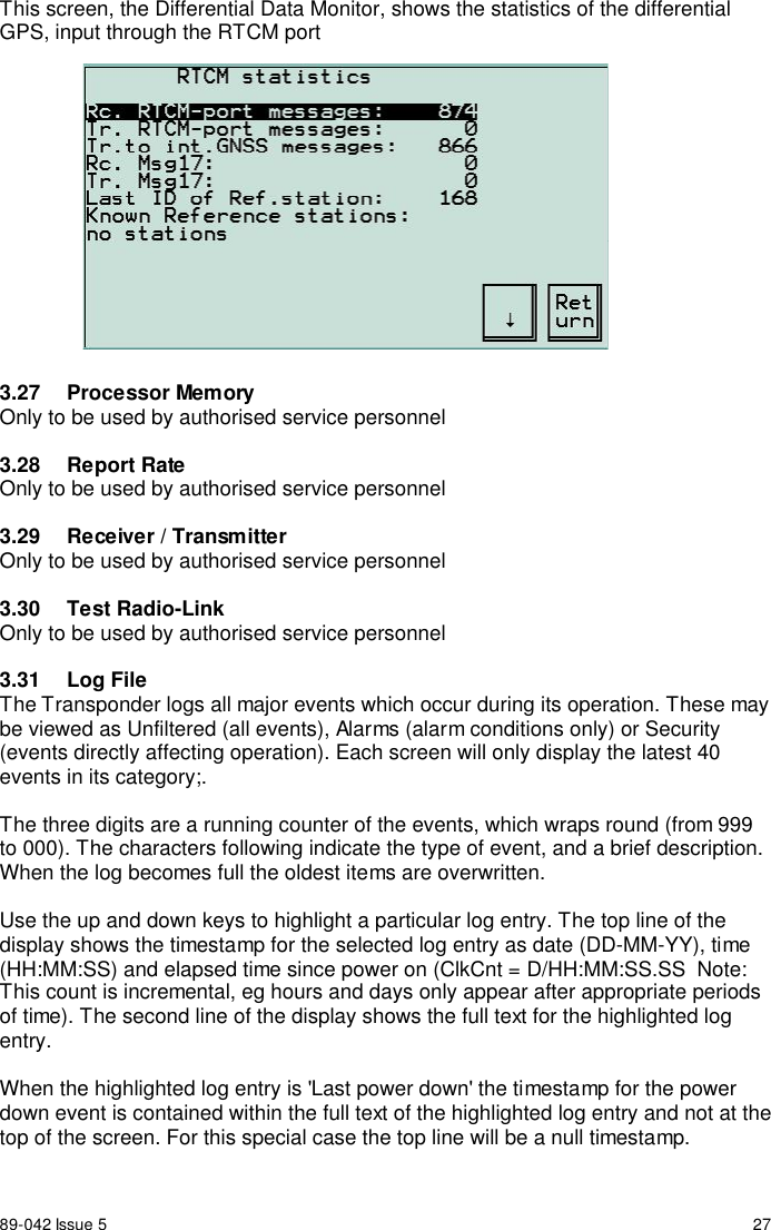
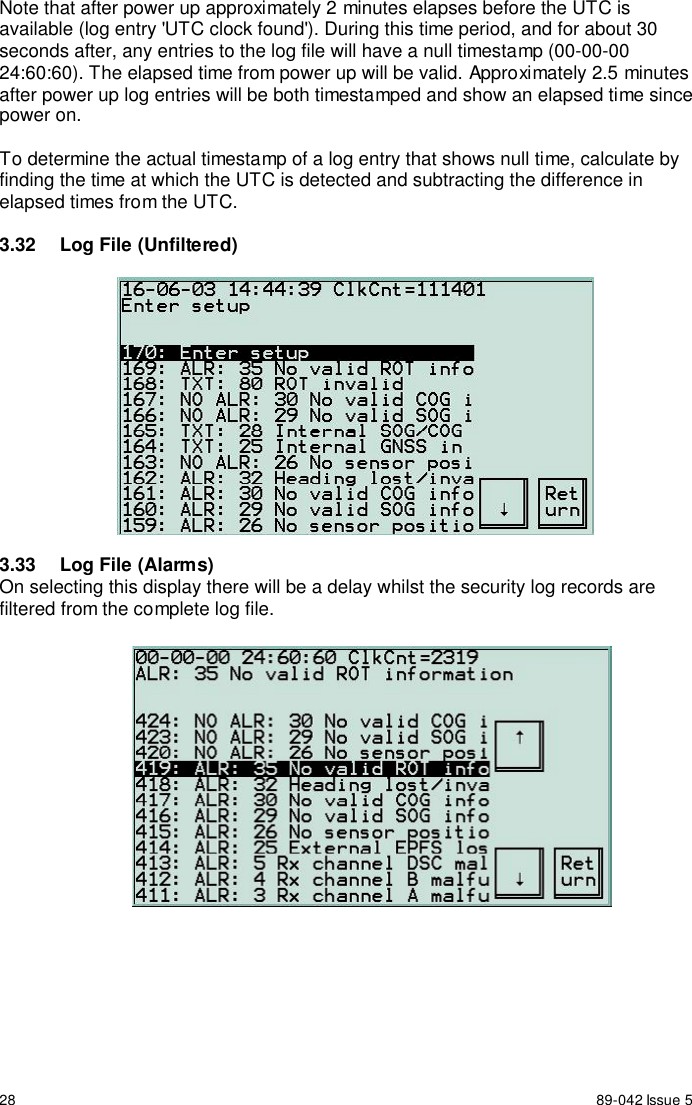
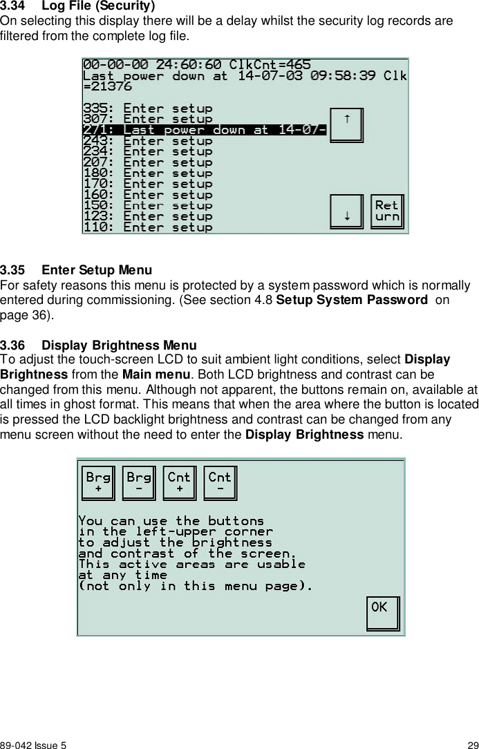
Operation Manual Section 2