Orolia MT-1 McMurdo/Transas MT-1 User Manual Operating Manual Section 1
Orolia Ltd McMurdo/Transas MT-1 Operating Manual Section 1
Orolia >
Contents
- 1. Installation Manual 89 041N
- 2. Operating Manual Section 1
- 3. Operation Manual Section 2
- 4. Operation Manual Section 3
Operating Manual Section 1
Operation Manual
UAIS Transponder System
89-042 Issue 5 19
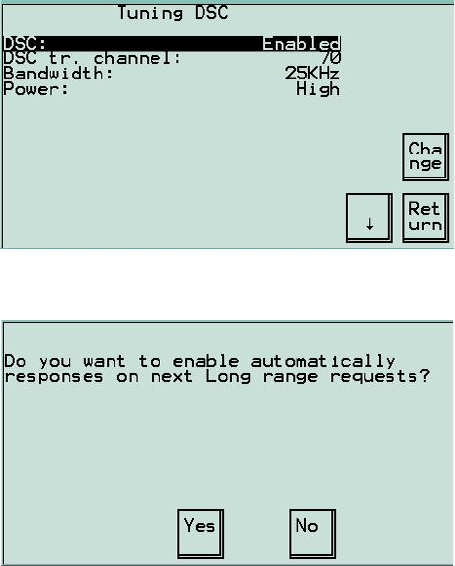
3.19 DSC Tuning Menu
UAIS can receive and process DSC information sent by Base stations. Periodically
lists of geographical regions and their associated parameters are transmitted on the
DSC channel. DSC is normally set to Channel 70.
Methods of tuning DSC:
DSC command from coastal station.
Manually from the VDU.
3.20 Long Range Request Menu
This feature is only available with a specialised interface to a suitable source.
20 89-042 Issue 5
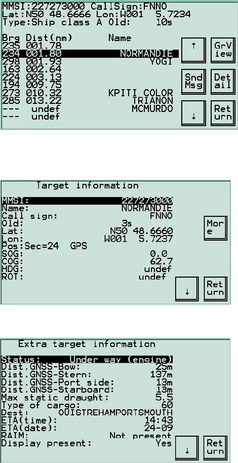
3.21 Other Stations Menu
This is the main working menu that displays information on all the received targets.
These targets can be viewed in three ways; as a list of vessel names along with
Bearing and Distance, more detailed information about individual vessels or as a
‘radar-style’ overview.
Individual targets can be viewed in more detail in 2 ways. Highlight a target; at the
top of the screen more detailed information can be seen about the selected target.
For full details, highlight the target and press Detail
Further information on the selected target is produced by selecting More
89-042 Issue 5 21
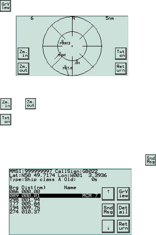
Press on the Other Stations menu to view the navigational situation in a
“radar-style” format.
This screen shows all received AIS stations and their velocity vector. The top left
number is the number of stations within the range of the display. The range, shown
at top right, corresponds with the outer ring of the displayed graphic.
Press or to change range between 1nm to 100nm in 7 steps.
Press to view or hide text captions (call signs) of the displayed targets.
3.22 Sending messages
From the Other Stations menu, short text messages can be sent to specific vessels
or groups of vessels. The text is generated using the on-screen keyboard and may
be sent to any or all of the indicated targets (which may be shore based stations).
From the target list, highlight the intended destination of the message and press
22 89-042 Issue 5
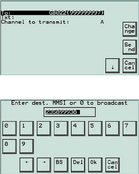
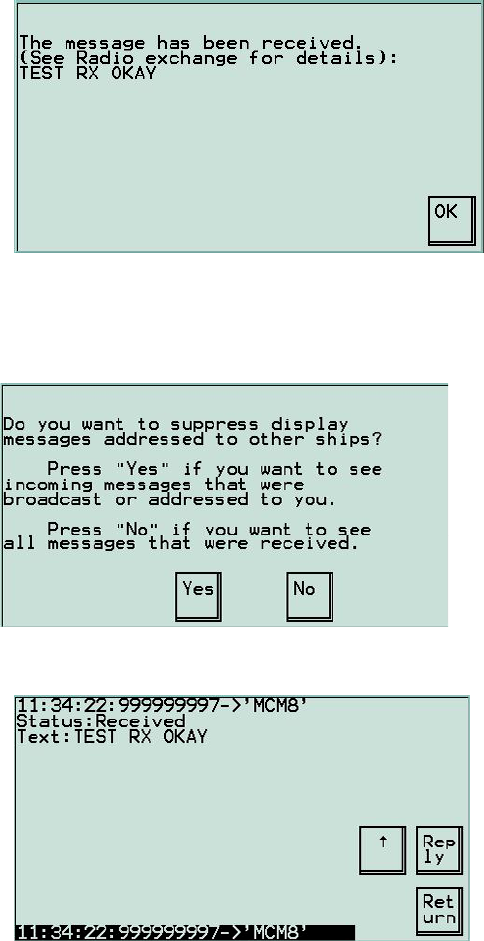
The top line of the screen shows the destination call sign and MMSI number. The
second line displays the message text and the bottom line shows the AIS channel
on which the message is to be sent, A or B. Either may be used.
To change the destination of the message, select the To: line and select Change
From this screen the MMSi of the recipient vessel may be changed, or a group
MMSI may be used, or the message may be broadcast to all ships. OK returns to
the previous screen.
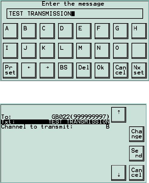
Highlight the Txt: line and select Change. A keyboard entry screen appears. Enter
the test to be transmitted, switching between screens to access different sections of
the keyboard.
89-042 Issue 5 23
When the message has been entered correctly, select OK. Select Send to transmit
the message.
To test the system, select a coast station and compose a message, for example: -
“This is an AIS test call, please acknowledge”.
If no acknowledgement is received the message will be re-transmitted up to four
times. If no acknowledgement is received after the four transmissions, try another
station in the list.
24 89-042 Issue 5
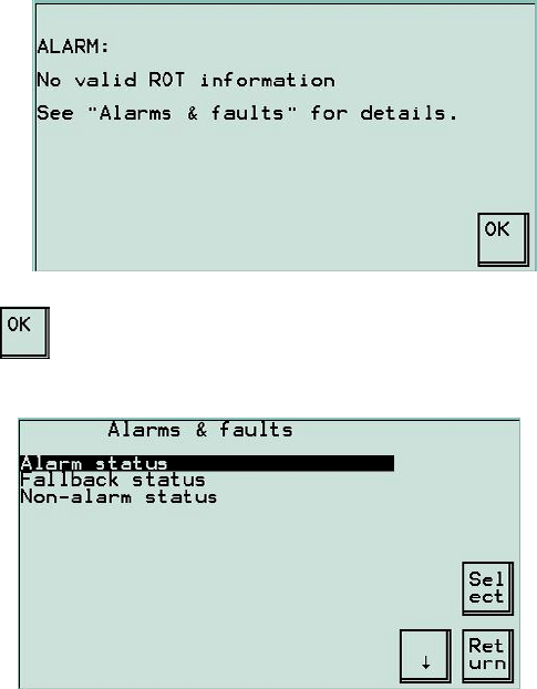
3.23 Receiving a message
When a message is received and identified as being for the particular vessel (ie it
has the correct MMSI number), a screen appears to alert the operator and to
display the text.
Further details of the message can be viewed by entering the Radio Exchange
screen.
3.24 Radio Exchange menu
Full details of received messages can be viewed.
The received messages are then displayed with time and date of transmission,
message text and details of the sender.
89-042 Issue 5 25
3.25 Alarms & Faults
When an alarm condition occurs a pop-up window will appear, eg
Press to acknowledge the alarm message.
To clear an alarm and deactivate the BIIT relay, first select Alarms & faults from
the Main menu then select Alarm status to view all the alarm conditions.
12 89-042 Issue 5
3.9 Dist.GNSS-Bow
Dist.GNSS-Stern
Dist.GNSS-Port-side
Dist.GNSS-Starboard
(Default = 0)
These values are set up during commissioning. Refer to section 4.15 for further
information.
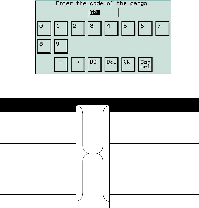
3.10 Type of Cargo
(Default = 0)
Enter to type of vessel and cargo.
Please see the tables below for details (tables are derived from the ITU-1371-1
standard).
Identifiers Used by Ships to Report Their Type
First Digit Second Digit
0 - Not used 0 - All ships of this type
1 - Reserved for future use 1 - Carrying DG, HS, or MP IMO
hazard or pollutant category A
2 - WIG ( Wing In Ground ) 2 - Carrying DG, HS, or MP IMO
hazard or pollutant category B
3 – Other ships
See table overleaf 3 - Carrying DG, HS, or MP IMO
hazard or pollutant category C
4 - HSC ( High Speed Craft ) 4 - Carrying DG, HS, or MP IMO
hazard or pollutant category D
5 – Special craft
See table overleaf 5 - Reserved for future use
6 - Passenger Ships 6 - Reserved for future use
7 - Cargo Ships 7 - Reserved for future use
8 - Tankers 8 - Reserved for future use
9 - Other types of Ship 9 - No additional information
DG = Dangerous Goods HS = Hazardous Substances MP = Marine Pollutants

89-042 Issue 5 13
Identifiers Used by Other Ships to Report Their Type
Identifier Number
First
Digit Second
Digit
Vessel Type
3 0 Fishing
3 1 Towing
3 2 Towing and length of the tow exceeds 200mtrs (656ft)
or breadth exceeds 25mtrs (82ft)
3 3 Engaged in dredging or underwater operations
3 4 Engaged in diving operations
3 5 Engaged in military operations
3 6 Sailing
3 7 Pleasure craft
3 8 Reserved for future use
3 9 Reserved for future use
Identifiers Used by Special Craft to Report Their Type
Identifier Number
First
Digit Second
Digit
Vessel Type
5 0 Pilot vessel
5 1 Search and rescue vessel
5 2 Tugs
5 3 Port tenders
5 4 Vessels with anti-pollution facilities or equipment
5 5 Law enforcement vessels
5 6 Spare – for assignments to local vessels
5 7 Spare – for assignments to local vessels
5 8 Medical transports (as defined in the 1949 Geneva
Conventions and Additional Protocols)
5 9 Ships according to Resolution No. 18 (Mob-83)
14 89-042 Issue 5
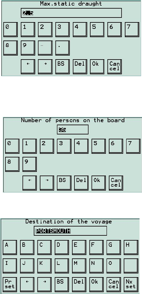
3.11 Max. Static Draught
(Default = 0.0)
Enter the maximum static draught of vessel (in metres) during the current voyage.
3.12 Persons on Board
(Default = 0)
Enter the total number of persons on-board during this voyage. This information is
normally provided at the Master’s discretion or on request from a competent
authority.
3.13 Destination
Enter the port of destination (Entered at Master’s discretion).
89-042 Issue 5 15
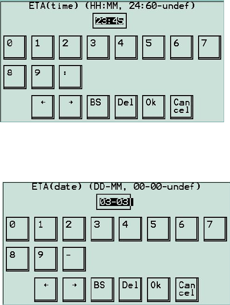
3.14 ETA (time)
(Default = 24:60 Undefined)
Enter the local Estimated Time of Arrival at port of destination. (Entered at Master’s
discretion).
3.15 ETA (date)
(Default = 00-00 Undefined)
Enter the Estimated Date of Arrival at port of destination. (00-00 = undefined)
(Entered at Master’s discretion).
16 89-042 Issue 5
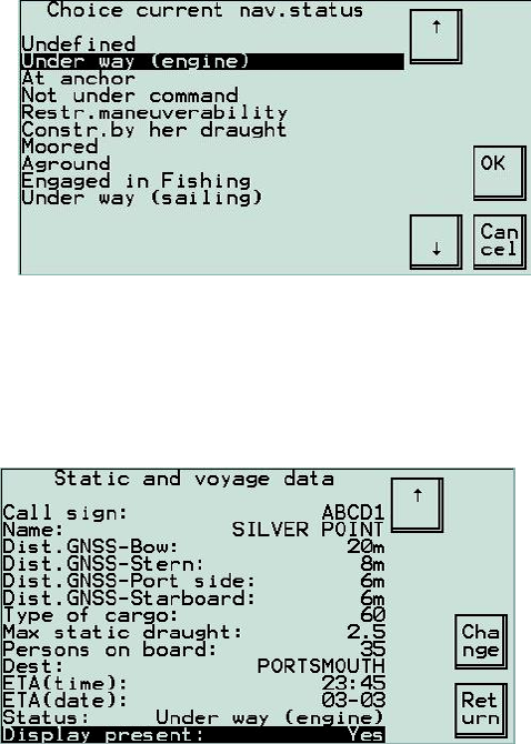
3.16 Status
(Default = Undefined)
Enter the navigational status of the vessel: -
3.17 Display Present
(Default = Yes)
When Display present is set to Yes, this option indicates to other UAIS stations
that the VDU is capable of showing received text messages. If the UAIS
Transponder is not connected to any application display (MKD, ECDIS, ARPA or
ECS) this parameter must be set to “No”.
89-042 Issue 5 17
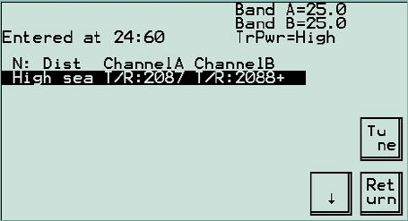
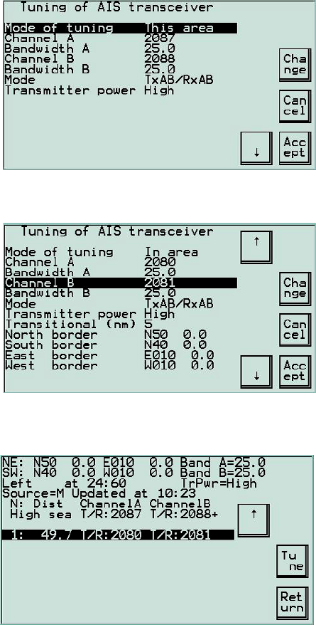
3.18 VHF Regions Menu
UAIS works on two radio channels at any time and may select those channels
depending on the geographical area. A list of up to 10 regions with their associated
channels can be stored in the permanent memory; if not in any of these regions,
UAIS uses the default channels of 2087 and 2088.
To view the region list stored in memory, select VHF regions option from the Main
set-up menu. The top item as highlighted above) indicates the frequencies used
outside the specified regions (ie at sea). Successive items, where present, show
manually entered frequencies and their parameters (eg transmitter power). The
station uses these entered frequencies within that specific region. “R” indicates the
frequency is used for receiving, similarly “T” is for transmitting.
Information on a particular region is shown at the top of the screen: geographical
co-ordinates, bandwidth and power of transmitter and time of entering or leaving the
region.
There are several ways a station can acquire region information: -
From a base station on the AIS channels.
From external devices through the input interfaces.
From a coastal station on CH70 DSC.
From an operator using the VDU.
18 89-042 Issue 5
Normally it is not necessary to enter the regions manually, as the station should
pick them up automatically, however it can still be done as shown in the following
section by selecting Tune in the previous screen
Changing the geographical location defines the region, and the associated
parameters may then be set.
A confirmation screen appears, then the new region and information is displayed on
the main screen.

Applicability of this manual
This manual is valid for all hardware and software issues of the equipment
described, and is kept current by updates.
When updates are posted, any incompatibility with earlier issues of hardware and/or
software will be highlighted here.
Disclaimer
Information contained in this manual is supplied in good faith, but is liable to change
without notice. McMurdo Limited disclaims any liability for consequences arising
from omissions or inaccuracies in the manuals and documentation provided with
this product.
IMPORTANT: Please take time to read this manual carefull
y
and to
understand its contents fully, so that you can operate your Transceiver
correctly.
Issue 5 of the Operation manual refers to V24 software,
which is expanded over earlier issues.
Table of Contents
1 INTRODUCTION..........................................................................1
1.1 About this Manual ......................................................................................1
1.2 Safety Summary.........................................................................................1
1.3 Rules of Operation Licensing.....................................................................2
1.4 Disclaimer ..................................................................................................2
2 PRODUCT DEFINITION ..............................................................3
2.1 System Overview .......................................................................................3
2.2 Compliance ................................................................................................4
2.3 UAIS Key Functions...................................................................................4
3 OPERATION ................................................................................5
3.1 Activation....................................................................................................5
3.2 Menu Navigation........................................................................................5
3.3 Initial Start-up.............................................................................................7
3.4 Set to Work ................................................................................................9
3.5 Show Sensors Menu..................................................................................9
3.6 Static & Voyage Data Menu.....................................................................10
3.7 Call Sign...................................................................................................11
3.8 Name........................................................................................................11
3.9 Dist.GNSS-Bow .......................................................................................12
3.10 Type of Cargo..........................................................................................12
3.11 Max. Static Draught..................................................................................14
3.12 Persons on Board ....................................................................................14
3.13 Destination...............................................................................................14
3.14 ETA (time)................................................................................................15
3.15 ETA (date)................................................................................................15
3.16 Status.......................................................................................................16
3.17 Display Present........................................................................................16
3.18 VHF Regions Menu..................................................................................17
3.19 DSC Tuning Menu ...................................................................................19
3.20 Long Range Request Menu.....................................................................19
3.21 Other Stations Menu................................................................................20
3.22 Sending messages...................................................................................21
3.23 Receiving a message...............................................................................24
3.24 Radio Exchange menu.............................................................................24
3.25 Alarms & Faults........................................................................................25
3.26 Show Status Menu...................................................................................26
3.27 Processor Memory...................................................................................27
3.28 Report Rate..............................................................................................27
3.29 Receiver / Transmitter..............................................................................27
3.30 Test Radio-Link........................................................................................27
3.31 Log File ....................................................................................................27
3.32 Log File (Unfiltered) .................................................................................28
3.33 Log File (Alarms)......................................................................................28
3.34 Log File (Security)....................................................................................29
3.35 Enter Setup Menu....................................................................................29
3.36 Display Brightness Menu .........................................................................29
4 COMMISSIONING..................................................................... 31
4.1 Initial Start-up ...........................................................................................31
Main Set-up Menu....................................................................................................34
4.3 General Set-up Menu...............................................................................35
4.4 MMSI........................................................................................................35
4.5 Purpose....................................................................................................35
4.6 IMO Number.............................................................................................36
4.7 RAIM Present...........................................................................................36
4.8 Setup System Password ..........................................................................36
4.9 Addressed Message Filter........................................................................37
4.10 Media Analyser Mode...............................................................................37
4.11 Max. Repeating Message 6, 12................................................................37
4.12 Transmission w/o Sync ............................................................................37
4.13 Enable Deleting Regions..........................................................................38
4.14 Extra Setup Menu.....................................................................................38
4.15 Intern. GNSS Position ..............................................................................38
4.16 Dist.Int.GNSS-Bow...................................................................................39
4.17 Out Position to MAIN & AUX....................................................................39
4.18 Alarm Signals Menu .................................................................................40
4.19 RS-422 Set-up Menu ...............................................................................41
4.20 Test Interfaces .........................................................................................43
4.21 DGNSS Set-up Menu...............................................................................44
4.22 Engineering Mode....................................................................................44
4.23 Other Options...........................................................................................44
4.24 Log File ....................................................................................................45
4.25 Saving Changes.......................................................................................45
5 MAINTENANCE AND SERVICING .......................................... 47
5.1 Preventative Maintenance........................................................................47
5.2 VDU Touch-Screen..................................................................................47
5.3 Electrical Connections..............................................................................47
5.4 Repair and Service...................................................................................47
5.5 Spare Parts ..............................................................................................47
5.6 World-wide Sales and Service .................................................................47
6 TROUBLESHOOTING.............................................................. 49
7 SPECIFICATION ....................................................................... 53
8 GLOSSARY............................................................................... 55
9 DECLARATION OF CONFORMITY......................................... 57

89-042 Issue 5 1
1 Introduction
1.1 About this Manual
This Operation Manual has been designed to help understand how to operate an
UAIS Transponder system as quickly as possible.
Please read this Manual thoroughly before attempting to use the UAIS Transponder
system.
The UAIS Transponder provides Communication, Navigation and Surveillance
(CNS) capabilities to either mobile or fixed stations. The primary purpose of this
UAIS is as a Class A mobile Ship-borne Transponder system.. A separate
Installation Manual is supplied, covering detailed information on installing and
interfacing an UAIS, assuming that the appropriate external equipment has already
been installed.
This Manual is a step by step guide to the procedures needed to successfully
operate an UAIS and will explain how to: -
• View received targets
• Check the status of the system and connected sensors
• Enter the static & voyage related data
• View VHF regions
• Respond to Long Range requests
• Filter incoming messages
• Check the status of alarms & faults
• Commission an installation
1.2 Safety Summary
WARNING: ENSURE THAT THE UAIS HAS BEEN CORRECTLY INSTALLED
IN ACCORDANCE WITH IMO GUIDELINES AND INSTALLATION MANUAL
BEFORE SWITCHING ON
WARNING: Transponder chassis can become hot during extended periods of
operation, avoid touching this when the Transponder is operating.
WARNING: Do not touch the VHF antenna or connecting cable when the
Transponder is in operation.
WARNING: Unauthorised opening of the Transponder system will invalidate the
warranty.
WARNING: Avoid using chemical solvents to clean the VDU as they can
damage the casing material.
289-042 Issue 5
WARNING: The use and operation of a UAIS transponder is legislated and
forms a part of the ship’s mandatory navigation equipment. It is therefore necessary
that the installation is certified (commissioned) and that certain information has to
be available before full operation of the transponder can take place. The ship’s IMO
and MMSI number has to be programmed into the transponder, as these form part
of the mandatory information that is transmitted.
WARNING: This product is sold or provided as merely an aid to navigation. It is
the responsibility of the user to exercise discretion and proper navigational and
seamanship skills.
WARNING: NOT ALL SHIPS CARRY AIS. The Officer of the Watch (OOW)
should always be aware that other ships and, in particular, leisure craft, fishing
boats and warships, and in some cases coastal shore stations (including Vessel
Traffic Systems (VTS) centres), might not be fitted with UAIS. The OOW should
always be aware that UAIS that is fitted on other ships as a mandatory carriage
requirement, might, under certain circumstances, be switched off based on the
Master’s professional judgement.
WARNING: The use of a Megger (High Voltage Insulation Tester) may damage
the equipment and therefore should not be used.
WARNING: Do not operate the equipment when persons are closer than 3
metres from the antenna. If any person (e.g. the operator) must be closer, then a
grounded RF shield should be interposed between that person and the antenna.
1.3 Rules of Operation Licensing
IMPORTANT: Operation of the UAIS Transponder is a part of the international radio
regulations and therefore the ship must possess a current VHF radio telephone
licence listing the UAIS system, and the equipment must be registered (Call Sign
and MMSI number). Please contact the relevant authority in your country for further
information.
1.4 Disclaimer
Information contained in this manual is correct at time of going to print, but is liable
to change without notice. McMurdo Limited disclaims any liability for consequences
arising from omissions or inaccuracies in the manuals and documentation provided
with this product.
89-042 Issue 5 3
2 Product Definition
2.1 System Overview
Universal Automatic Identification System (UAIS) is a maritime VHF based
transponder system that provides high-speed automated communication from ship-
to-ship and ship-to-shore, of vessel, voyage and safety related data. This UAIS
transponder and touch screen VDU display system is the latest in state-of-the-art
technology and is designed to meet the latest IMO SOLAS requirements. The UAIS
transponder transmits the ship’s navigational data to other vessels, as well as shore
based VTS systems. Utilising marine VHF channels, UAIS is primarily designed as
a ship-borne mobile station and consists of an integral GNSS engine used for
timing, one VHF transmitter, three VHF receivers and a computer unit. Interfacing to
external GNSS used for navigation, a VHF antenna, a gyrocompass, and an
optional ECDIS or ARPA display system is made easy by the built-in screw terminal
board and the intuitive operating menu system on the touch-screen display unit.
The VDU is designed to fulfil the minimum SOLAS requirements for system set-up
and display of the received target information. However the large LCD touch screen
display also gives the user easy access to the menu system that displays the
received targets on a graphical, radar-like display.
The UAIS Transponder transmits the following information, which is separated into
three basic information groups:
Static - Vessel name, type, length and breadth, MMSI and IMO numbers and
GNSS antenna location.
Dynamic – Position, accuracy and integrity, time, course and speed over ground
and navigational status.
Voyage – Cargo, draft, port of destination and estimated time of arrival.
• In addition to this information, UAIS can transmit and receive short text
messages regarding navigation safety that include, warnings of floating objects,
collisions, meteorological situation, etc.
• Differential correction information for GNSS can also be conveyed through the
UAIS, increasing the accuracy of positional information between 2 and 10
metres. This significantly increases vessel safety, thus improving the marine
environment as well as the safety of life at sea.
489-042 Issue 5
2.2 Compliance
This UAIS is designed to comply with international standards and is approved in
accordance with the high standards of the European Marine Equipment Directive:
• MSC.74(69)
• ITU-R M.1371, ITU-R M.1084-4, ITU-R M.823-3, ITU-R M.493-9
• IEC 60945, IEC 61993-1,2, IEC 61162-1,2,3, IEC 61108
• ETS 300 113
2.3 UAIS Key Functions
¾ Automatic identification of other UAIS equipped vessels.
¾ Self-organising control of access to the radio channels.
¾ Reception of data via the radio channels from other vessels and coast
centres.
¾ Transmission of own vessel data via the radio channels for use by other
vessels and coast centres.
NOTE: Two channels, A and B, are used for transmission.
¾ Storage of static data intended for automatic transmission via the radio
channels.
¾ Output of data received via the radio channels from other UAIS objects for
presentation on the minimum display.
¾ Determination of the position and motion of own vessel if the external
GNSS receiver fails by utilising the internal timing GNSS receiver.
¾ Application of GNSS differential corrections using information supplied
from a supplementary receiver.
¾ The application of GNSS differential corrections using information received
from a controlling station via the VDL (VHF Data Link) channel.
¾ The output of Built-In-Integrity Test (BIIT) information regarding the UAIS
status on the main (e.g. ECDIS) display interface, auxiliary (e.g. Pilot)
display interface and also the minimum display.
¾ Delivery to the display of bearings and distances to the vessels, calculated
from their co-ordinates, obtained via the VDL channel.
89-042 Issue 5 5
3 Operation
Please read all the warning notices at the front of this manual before turning on the
Transponder.
3.1 Activation
It is recommended that UAIS should not be switched off and should remain in
operation continuously. However, based on the Master’s professional judgement,
either transmission may be inhibited or the UAIS may be switched off entirely if
continuous operation might compromise the ship’s safety or security. Reactivation
must take place as soon as the source of danger has disappeared. This might be
necessary in waters where pirates or armed robbers are known to operate. It might
also be necessary to switch off UAIS during some cargo handling operations.
Actions of this nature should always be recorded in the ship’s logbook.
3.2 Menu Navigation
The “keyboard” is the touch-sensitive screen of the VDU. The keys displayed
change according to the other information on the screen. Touch a key square to use
that key function.
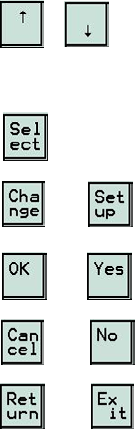
All on-screen menus follow the same basic principles to navigate around them.
Using the up and down arrows allows the operator to move quickly
and easily through the current menu system.
Once the required item is highlighted PRESS either: -
to enter a sub-menu.
or to change the data in the selected field.
or to confirm the change.
or to stop the action and return to the previous command.
or to go to the previous menu.
Some menu options are automatically selected depending upon the input data
available.
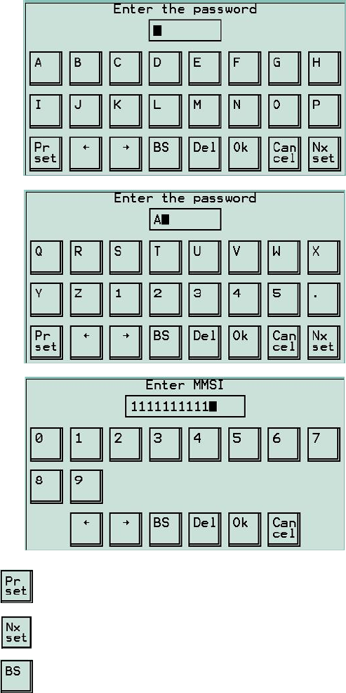
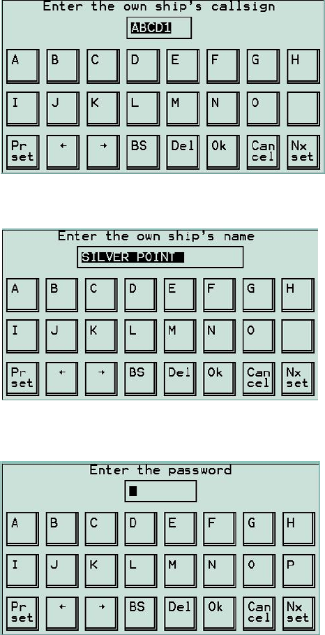
The data entry keyboard is divided into three screens as shown overleaf.
689-042 Issue 5
Press to move to the previous character set
Press to move to the next character set
Press to Back Space
89-042 Issue 5 7
Press to Delete a character
Press or to move the cursor
3.3 Initial Start-up
Ensure that power is available to the Transponder unit and that the main power
on/off switch, located to the left side of the cable entry of the Transponder, is
switched to the “on” position (green LED illuminated). At this point the Transponder
is active and will wait for 1 minute before entering the network and starting
transmission as it is listening to other stations to determine its own transmission
time slot sequence schedule.
Press to switch on VDU. To switch off, press and hold for 2
seconds.
NOTE: When re-starting the VDU, the screen displayed will be that when the VDU
was switched off.
For a complete overview of the operating menu structure, please refer to
Appendix 1 “UAIS Operating Menu Hierarchy” at the back of this Manual.
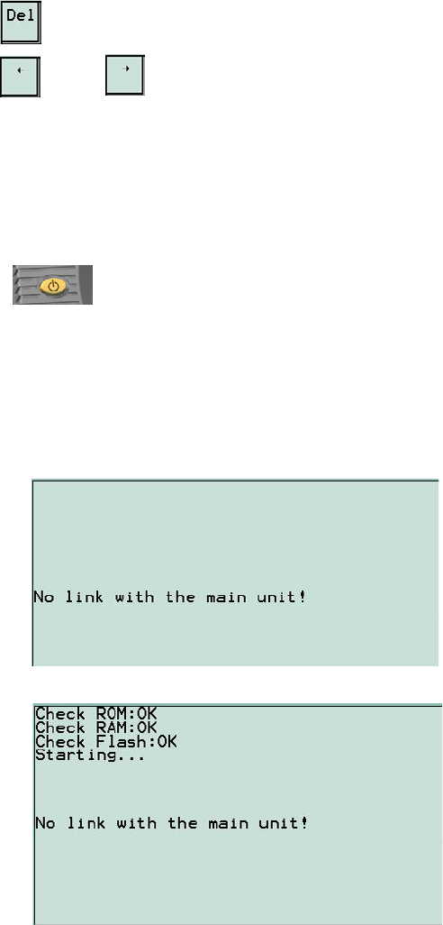
At power-up the system conducts a series of self-tests and the results are displayed
on-screen as follows:-
889-042 Issue 5
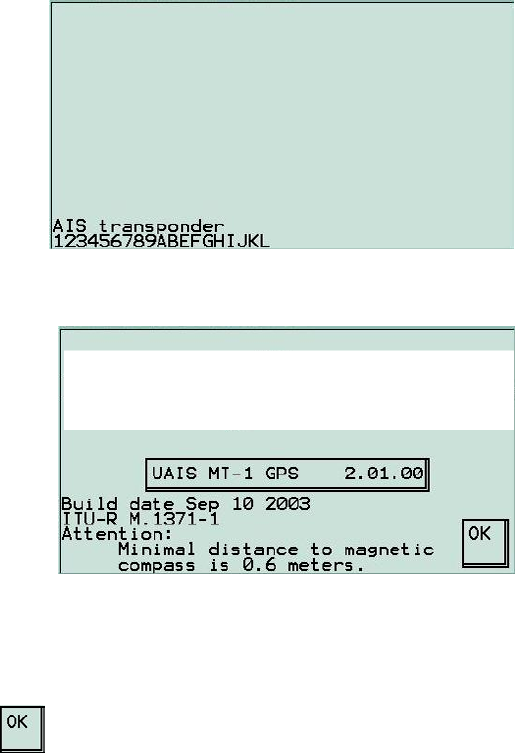
After successful completion of the self-test and communication between the VDU
and the transponder has been established the following screen will appear.
The welcome screen giving the GNSS type (GPS or GLONASS), software version,
and software build date then appears, which confirms that the VDU is ready for
operation.
Press to enter the Main Menu.
89-042 Issue 5 9
3.4 Set to Work
NOTE: If the display is not easy to read, refer to section 3.35 which details how to
adjust the display.
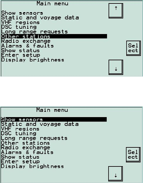
The next screen to appear is the Main menu that contains all the basic functions
required to successfully operate a class A UAIS ship-borne station.
The Other stations option in this menu is where all received target information can
be monitored. (See section 3.21 on page 20)
When in operation mode the Main menu appears with the following options: -
3.5 Show Sensors Menu
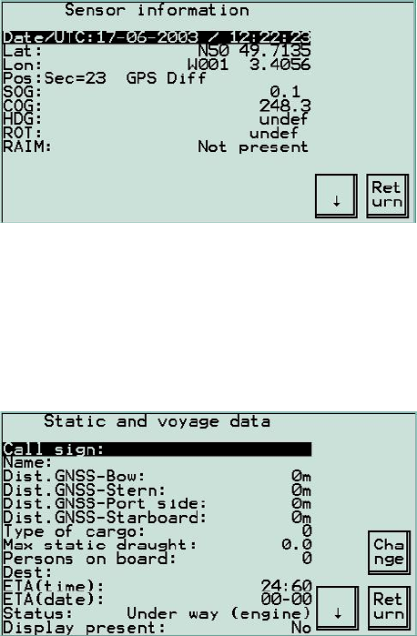
10 89-042 Issue 5
This screen will display navigation data used by UAIS. Normally the navigation data
is received via the input ports Sens1, Sens2 and Sens3 as well as the RTCM port
for differential corrections. If the data is not being received via these interfaces,
UAIS can use it’s own internal GNSS, providing this facility has been enabled (see
section 4.14 on page 38). Co-ordinates for non-mobile stations may be pre-set
during commissioning.
3.6 Static & Voyage Data Menu
In this menu, the static and voyage related data may be reviewed or changed. This
is not password protected, allowing ship’s information to be entered or changed at
any time.
89-042 Issue 5 11
3.7 Call Sign
Enter the Ships radio call sign.
3.8 Name
Enter the Ship's registered name (maximum 20 characters).
To confirm the change in ship’s name the system password must be entered. (See
section 4.8 Setup System Password on page 36)