Orolia MT-1 McMurdo/Transas MT-1 User Manual Operation Manual Section 3
Orolia Ltd McMurdo/Transas MT-1 Operation Manual Section 3
Orolia >
Contents
- 1. Installation Manual 89 041N
- 2. Operating Manual Section 1
- 3. Operation Manual Section 2
- 4. Operation Manual Section 3
Operation Manual Section 3
89-042 Issue 5 45
4.24 Log File
This log file is detailed in section 3.31
4.25 Saving Changes
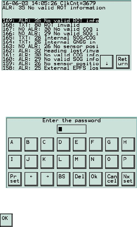
If any changes have been made to the settings, UAIS will ask for confirmation of
those changes.
To complete the process the correct password will need to be entered.
PRESS to exit and return to Main menu.
This action returns UAIS to normal transmission.
89-042 Issue 5 47
5 Maintenance and Servicing
5.1 Preventative Maintenance
The UAIS transponder system is an essential part of the ship’s navigation system
and is a vital component for the safety of the ship and its crew. It is therefore very
important to maintain the system and its installation to a very high standard. The
design of the UAIS transponder ensures that maintenance can be kept to a
minimum, however it is good practice to perform a performance check at least once
every week.
5.2 VDU Touch-Screen
To optimise performance of the touch-screen VDU and cabinet, ensure they are
kept clean and grease-free. Use a clean damp cloth, or for heavier deposits use a
clean, damp cloth and a mild solution of dish washing detergent and water. Do not
use any spirit or alcohol based solvents, gasoline or oils.
5.3 Electrical Connections
Periodically check the electrical connections; ensure that no cables are frayed or
worn, and that all connections are tight and sound.
5.4 Repair and Service
With the exception of the fuses located on the Screw Terminal Board, there are no
user serviceable parts. Changing fuses is described in Section 6 – Troubleshooting.
Removal of the inspection plates other than by an Authorised Service Technician
will void warranty. If having followed the Troubleshooting Guide (Section 6) UAIS is
still inoperable, please call your local Service Centre.
5.5 Spare Parts
Use only manufacturers genuine spare parts. No liability can be accepted for
equipment failure due to incorrect replacement parts being used.
5.6 World-wide Sales and Service
For a complete list of worldwide sales and service agents, please contact your
product supplier.

89-042 Issue 5 49
6 Troubleshooting
Perform the following checks BEFORE calling an authorised Service Centre.
Symptom Cause Cure
1) No power to
Transponder
2) System fuse
blown
No Green light illuminated on
Transponder
1) Check fuse or circuit
breaker at 24VDC
supply point.
2) Check/replace system
fuse in Transponder.
Use only 10Amp blade type
fuse
No text on screen
1) VDU installation
2) Display fuse
blown
Green light is illuminated on
Transponder
1) Check display
cable/connections
2) Check display fuse in
Transponder.
Use only 1Amp blade type
fuse
Text appears on screen
but is too dark or light to
read
LCD backlight and/or
contrast out of
adjustment
1) Select Display
Brightness from Main
menu
2) Adjust LCD backlight
and/or contrast (See
section 3.36 Display
Brightness Menu on
page 29)
At power-up, self-test
shows one of the
following messages: -
ROM : Error
RAM : Error
FLASH : Error
Central processor
failure Contact Service Centre
Tx malfunction alarm
activates Transmitter PCB
failure Contact Service Centre

50 89-042 Issue 5
Symptom Cause Cure
Antenna VSWR exceeds
limit alarm activates Antenna installation 1) Check
cable/connections
2) Check antenna
Rx channel A
malfunction alarm
activates
Receiver PCB failure Contact Service Centre
Rx channel B
malfunction alarm
activates
Receiver PCB failure Contact Service Centre
Rx channel DSC
malfunction alarm
activates
Receiver PCB failure Contact Service Centre
General failure alarm
activates
1) No power to
Transponder
2) System fuse
blown
No Green light illuminated on
Transponder
1) Check fuse or circuit
breaker at 24VDC
supply point.
2) Check/replace system
fuse in Transponder.
Use only 10A blade type
fuse
MKD connection lost
alarm activates VDU installation Check display
cable/connections
External EPFS lost alarm
activates GPS signal lost 1) Check GPS
2) Check
cable/connections
No sensor position in use
alarm activates GPS installation 1) Check
cable/connections
2) Check GPS
3) Enable internal GPS to
provide position (See
section 4.15 Intern.
GNSS Position on page
38)
No valid SOG information
alarm activates 1) Bottom Track
Log signal lost
2) GPS signal lost
1) Check GPS
2) Check
cable/connections

89-042 Issue 5 51
Symptom Cause Cure
No valid COG
information alarm
activates
GPS signal lost 1) Check GPS
2) Check
cable/connections
Heading lost/invalid
alarm activates 1) Gyro compass
2) Gyro interface
3) Connection between
Transponder and
Gyro / interface
1) Check Gyro or
Interface Unit
2) Check
cable/connections
No valid ROT information
alarm activates 1) Gyro compass
2) Gyro interface
3) Connection between
Transponder and
Gyro / interface
3) Check Gyro or
Interface Unit
4) Check
cable/connections
No TDMA
synchronisation alarm
activates
Integral GPS signal lost 1) Check
cable/connections
2) Check antenna
Tx amplifier malfunction
alarm activates Transmitter PCB failure Contact Service Centre
No own reports mode
alarm activates Purpose of station set to
No own reports mode Re-assign purpose of
station (see section 4.5
Purpose on page 35)
Changing a fuse
There are two fuses, located on the Screw Terminal Board, which are designed to
be changed by the user. These are the only user servicable parts.
Fuse description Fuse value Part No.
Main system fuse 10.0 Amp 99-077
VDU system fuse 1.0 Amp 99-076
Switch off the Transponder, undo the six screws retaining the cover, then lift off the
cover. Ensure that the power is off before attempting to remove a fuse. The fuse
link is visible through the transparent body of the fuse.
Ensure that the fuses are not interchanged. The values are clearly marked on the
board.
When the fuses have been checked to be intact, replace the cover, fit the six
screws and tighten carefully.

89-042 Issue 5 53
7 Specification
General Data
Power consumption: 75W
Power supply: 24 VDC –10% +30%
AIS1 (CH87B) 161.975 MHz
AIS2 (CH88B) 162.025 MHz
Default frequencies:
DSC (CH70) 156.525 MHz
Operating temperature: -15°C to +55°C
Storage temperature: -20°C to +70°C
Environmental: As per IEC 60945
Transponder size / weight 308mm x 416mm x 93mm 7kg
VDU size / weight 219mm x 151mm x 76mm 1kg
GPS size / weight ∅ 115mm x 76mm 0.24kg
GPS receiver: Used for TDMA timing. Optionally used for
navigational information.
GPS antenna: Patch antenna with built-in 30dB pre-
amplifier
GLONASS receiver Optional GLONASS version available
Transmitter
Power output: 12.5 W or 2.0 W
Frequency range: 156.025 – 162.025 MHz
Antenna impedance: 50 Ω
TDMA Receivers
Sensitivity: (PER) < 10% at –107 dBm (25kHz)
Frequency range: 156.025 – 162.025 MHz
Channel spacing: 12.5 or 25 kHz
Modulation: GMSK
Data rate: 9,600 bits/s
Frequency stability: < ± 1ppm
DSC Receiver
Sensitivity: BER <10-4 at 107 dBm
Frequency range: 155.3 – 162.5 MHz
Channel spacing 25kHz
Modulation 1300Hz/2100Hz - FSK
Frequency stability < ± 1ppm
Serial inputs/outputs
SENS1/2/3 IEC61162-2 (RS-422 input only)
DISPLAY, LONG RANGE,
MAIN, AUX/PILOT, RTCM IEC61162-2 (RS-422 input & output)

89-042 Issue 5 55
8 Glossary
4S Ship-to-Ship & Ship-to-
Shore
AIS Automatic Identification
System
ALM Alarm
ANT Antenna
ARPA Automatic Radar Plotting
Aid
ASCII American Standard Code
for Information
Interchange
ATA Automatic Tracking Aid
AtoN Aid to Navigation
AUTO Automatic
AUX Auxiliary
BAS Basic AIS Services
BAT Battery
BIIT Built-In Integrity Test
BIOS Basic Input / Output
System
BRG Bearing
BRILL Display Brilliance
CG Coast Guard
CH Channel
CHG Change
CLR Clear
CNCL Cancel
CNS Communication,
Navigation & Surveillance
COG Course Over Ground
CONTR Contrast
CPA Closest Point of Approach
CPU Central Processing Unit
CSE Course
DEL Delete
DEST Destination
DG Dangerous Goods
DGLONASS Differential GLONASS
DGNSS Differential GNSS
DGPS Differential GPS
DISP Display
DIST Distance
DSC Digital Selective Calling
DTE Data Terminal Equipment
ECDIS Electronic Chart Display
and Information System
ECS Electronic Chart System
EGNOS European Geo-stationary
Navigational Overlay
System
ENC Electronic Navigation
Chart
ENT Enter
EPA Electronic Plotting Aid
EPFD Electronic Position Fixing
Device
EPFS Electronic Position Fixing
System
EPIRB Electronic Position
Indicating Radio Beacon
ERR Error
ETA Estimated Time of Arrival
EXT External
FATDMA Fixed Access Time
Division Multiple Access
FCC Federal Communications
Commission
FREQ Frequency
GLO or
GLONASS Global Orbiting Navigation
Satellite System
GMDSS Global Maritime Distress
and Safety System
GND Ground
GNSS Global Navigation Satellite
System
GPS Global Positioning System
GYRO Gyro Compass
HDG Heading
HS Hazardous Substances
HSC High Speed Craft
I/O Input / Output
IBS Integrated Bridge System
ID Identification
IEC International
Electotechnical
Commission
IMO International Maritime
Organisation
IN Input
INFO Information
INS Integrated Navigation
System
ITDMA Incremental Time Division
Multiple Access
ITU-R International
Telecommunications
Union –
Radiocommunications
Bureaux

89-042 Issue 556
KN Knots
L/L Latitude / Longitude
LAT Latitude
LON Longitude
LOST TGT Lost Target
MMetres
MAG Magnetic
MAN Manual
MED Marine Equipment
Directive
MF/HF Medium Frequency/High
Frequency
MID Maritime Identification
Digit
MIN Minimum
MKD Minimum Keyboard and
Display
MMSI Maritime Mobile Service
Ide nti ty
MOB Man Overboard
MP Marine Pollutant
NAV Navigation
NM Nautical Mile
NMEA National Marine
Electronics Association
NUC Not Under Command
OOW Officer Of the Watch
OS Own Ship
OUT Output
POSN Position
PPU Portable Pilot Unit
PWR Power
RAIM Receiver Autonomous
Integrity Monitoring
RCC Rescue Co-ordination
Centre
RNG Range
RORO Roll On, Roll Off
ROT Rate Of Turn
RR Range Ri ngs
RTCM Radio Technical
Commission for Maritime
services
RTE Route
Rx Receive / Receiver
SAR Search And Rescue
SEL Select
SOG Speed Over Ground
SOTDMA Self-Organising Time
Division Multiple Access
SPD Speed
SPEC Specification
STBD Starboard
STBY Standby
STW Speed Through Water
TCPA Time to Closest Point of
Appoach
TDMA Time Division Multiple
Access
TGT Target
TPR Transponder
TRK Track
TSS Traffic Separation Scheme
TTG Time To Go
Tx Transmit / Transmitter
Tx/Rx Transceiver
UAIS Universal Automatic
Identification System
UHF Ultra High Frequency
UTC Universal Time Co-
ordinate
VDL VHF Data Link
VDU Visual Display Unit
VHF Very High Frequency
VOY Voyage
VSWR Virtual Standing Wave
Ratio
VTS Vessel Traffic Systems
WAAS Wide Area Augmentation
System
WCV Waypoint Closure Velocity
WGS World Geodetic System
WIG Wing In Ground
WPT Waypoint
89-042 Issue 5 57
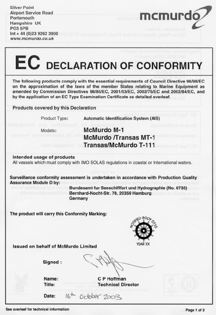
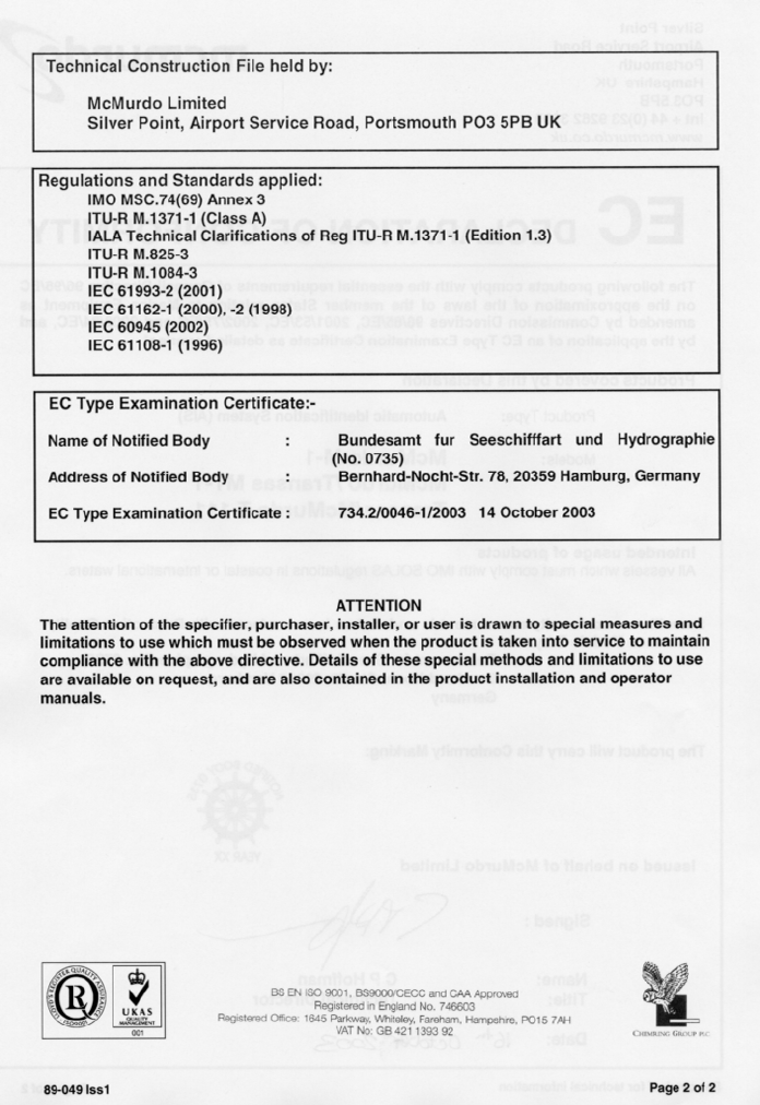
9 Declaration of Conformity
89-042 Issue 4
58