Ott Hydromet Business Unit Adcon Telemetry A724-S4 Telemetry transceiver User Manual A724S4 User Manual
Adcon Telemetry GmbH Telemetry transceiver A724S4 User Manual
UserManual.wiki
>
Ott Hydromet Business Unit Adcon Telemetry
>
A724 S4 User Manual
User Manual
Navigation menu
Upload a User Manual
Namespaces
Wiki Guide
HTML
PDF
Info
Views
User Manual
Discussion / Help
Navigation

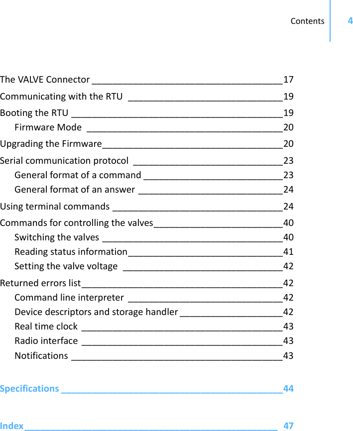
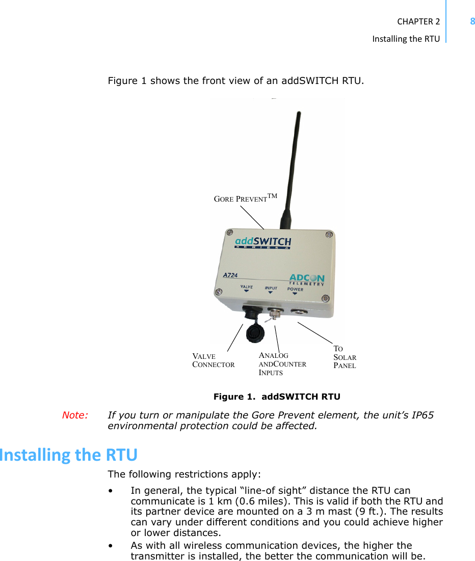
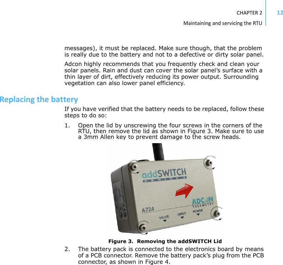
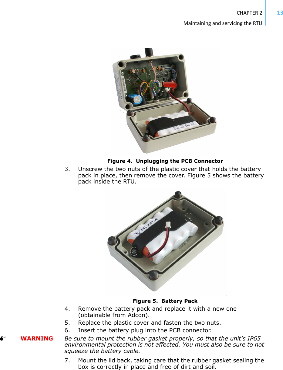

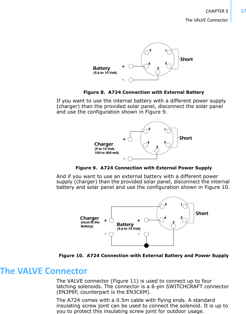
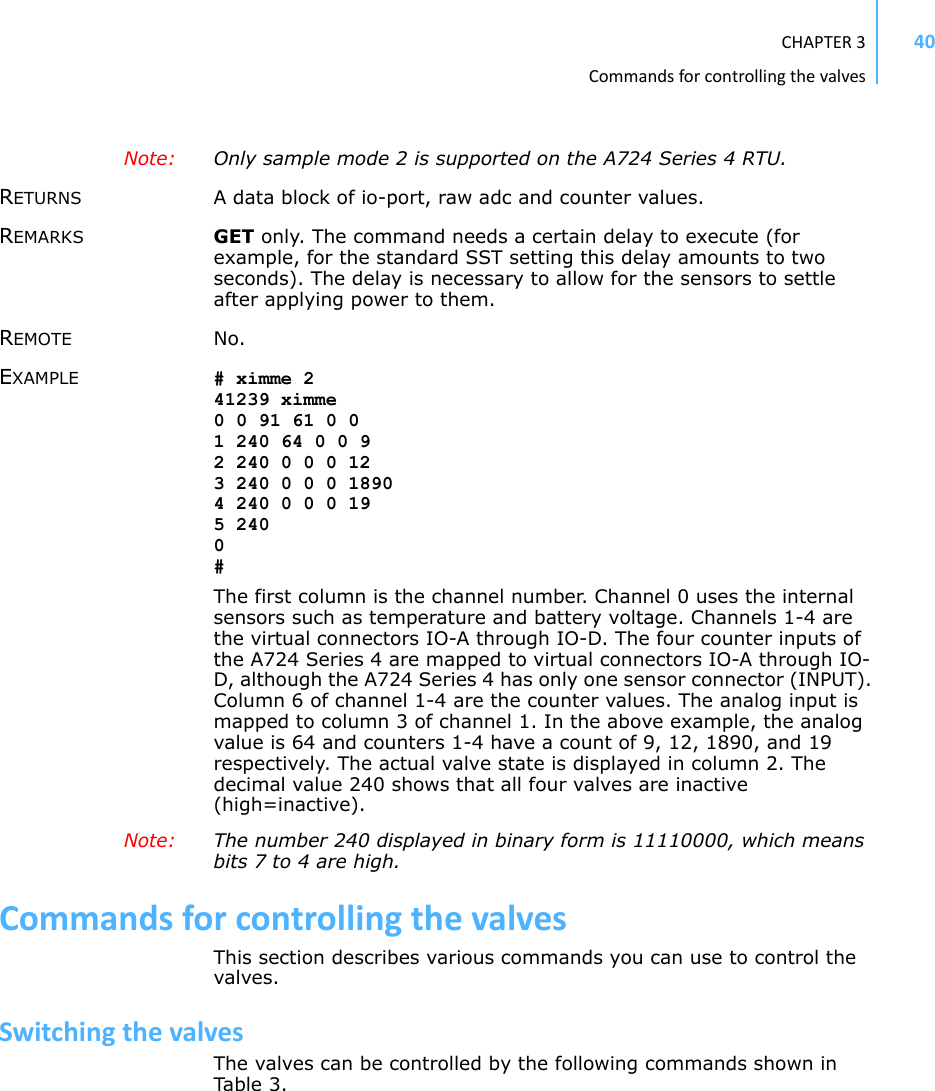
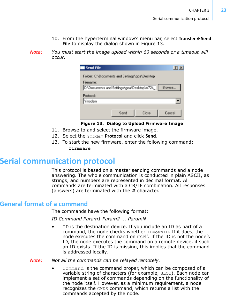
![CHAPTER3UpgradingtheFirmware20In bootloader mode, the command line interface’s prompt is the character >. Therefore, to reboot the RTU just type the following after you see the > prompt: rebootAn alternative way to boot the RTU is to disconnect the battery and after a few seconds reconnect it.For a list of the available commands, type Help at the > prompt.Available commands:upgrade [baudrate] ... upgrade from Y-modem downloadversion ... show the version of the bootloaderstate ... show the board statereboot [id] ... reboot the RTUfirmware ... start the firmwarehelp ... display this help textNote: For some commands, such as the reboot command, you can supply the ID of the RTU. FirmwareModeWhen you enter firmware mode, the following message is displayed in the Hyperterminal window:Checking firmware ... firmware found!41239 0#The bootloader scans the program memory for a valid firmware by testing the checksum, which takes a moment. If everything is correct, the "firmware found!" message appears.A moment after the firmware is found, the RTU’s identification number (for example, 41239) and error code (in this example, 0) are displayed. After another moment, the firmware mode’s command line interface prompt is displayed (#). If you need to return to bootloader mode when you’re in firmware mode, enter the Reboot <ID> command at the prompt.See “Using terminal commands” on page 24 for commands available in firmware mode.UpgradingtheFirmwareNote: This section is included for informational purposes. You will rarely need to upgrade the firmware. However, when you do need to do so,](https://usermanual.wiki/Ott-Hydromet-Business-Unit-Adcon-Telemetry/A724-S4/User-Guide-1160728-Page-20.png)
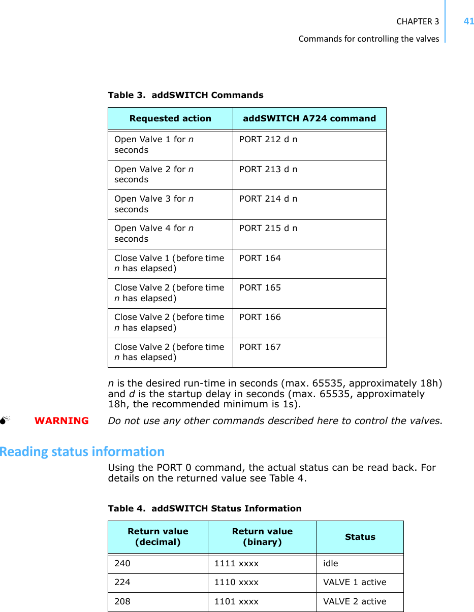
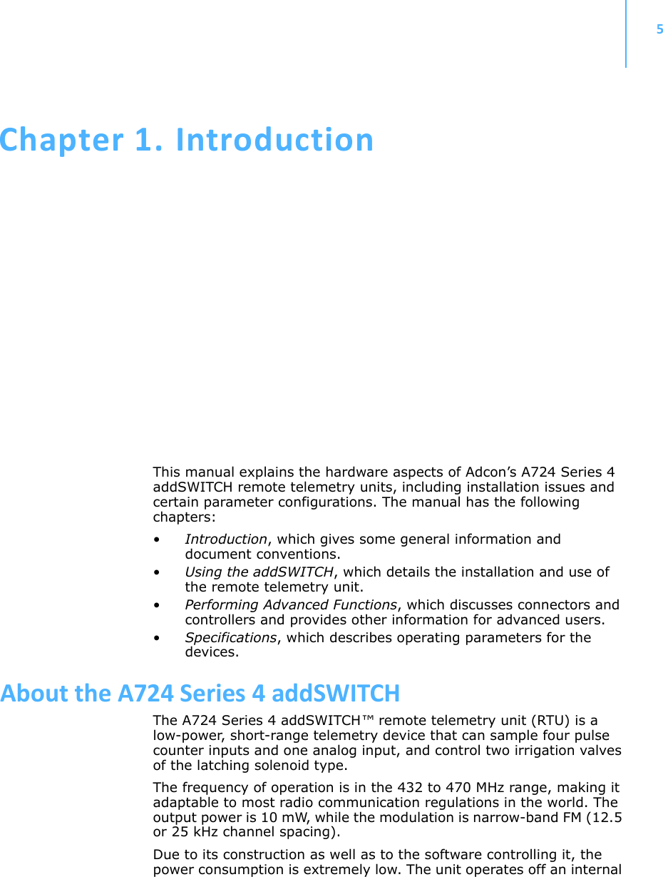
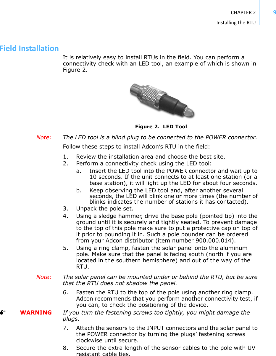
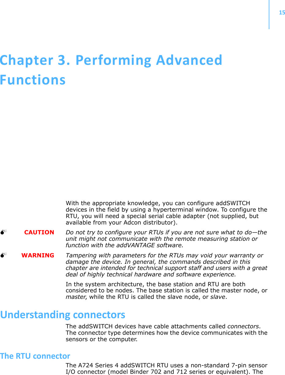
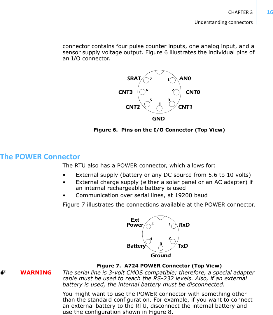
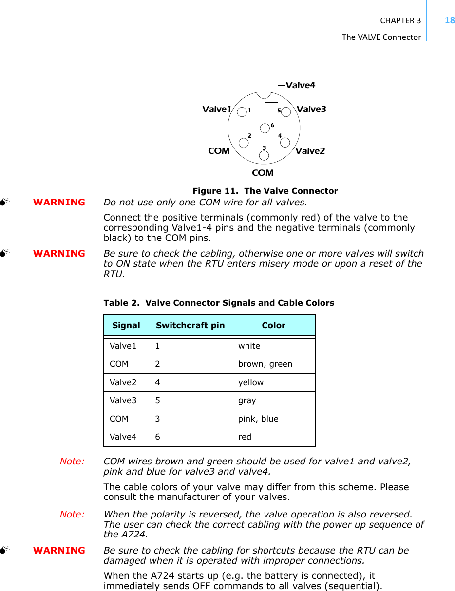
![CHAPTER3UpgradingtheFirmware22Figure 12. Hyperterminal and Com Port Properties Dialogs5. In the Bitspersecond field, select 115200.6. Select OK in the com port’s Properties dialog to close it.7. Select OK in the hyperterminal’s Properties dialog to close it.8. Back in the hyperterminal window, press Enter to continue the upgrade.---------------------------------------------------The current firmware image must be erased for the upload.If you continue now, you *MUST* upload a valid firmware image for an A724_S4!Continue? [y/n]: WARNING When you continue with the upgrade process, any existing firmware image in the RTU’s flash memory will be erased! You must supply a valid image for upload or the RTU will have only bootloader capabilities (that is, it will have no radio capabilities).9. Enter Y to continue the upgrade.The bootloader starts sending the letter C (for connect)Starting flash blankcheck and erase process. . . done---------------------------------------------------Start the Y-modem upload now!Starting CCCCC](https://usermanual.wiki/Ott-Hydromet-Business-Unit-Adcon-Telemetry/A724-S4/User-Guide-1160728-Page-22.png)
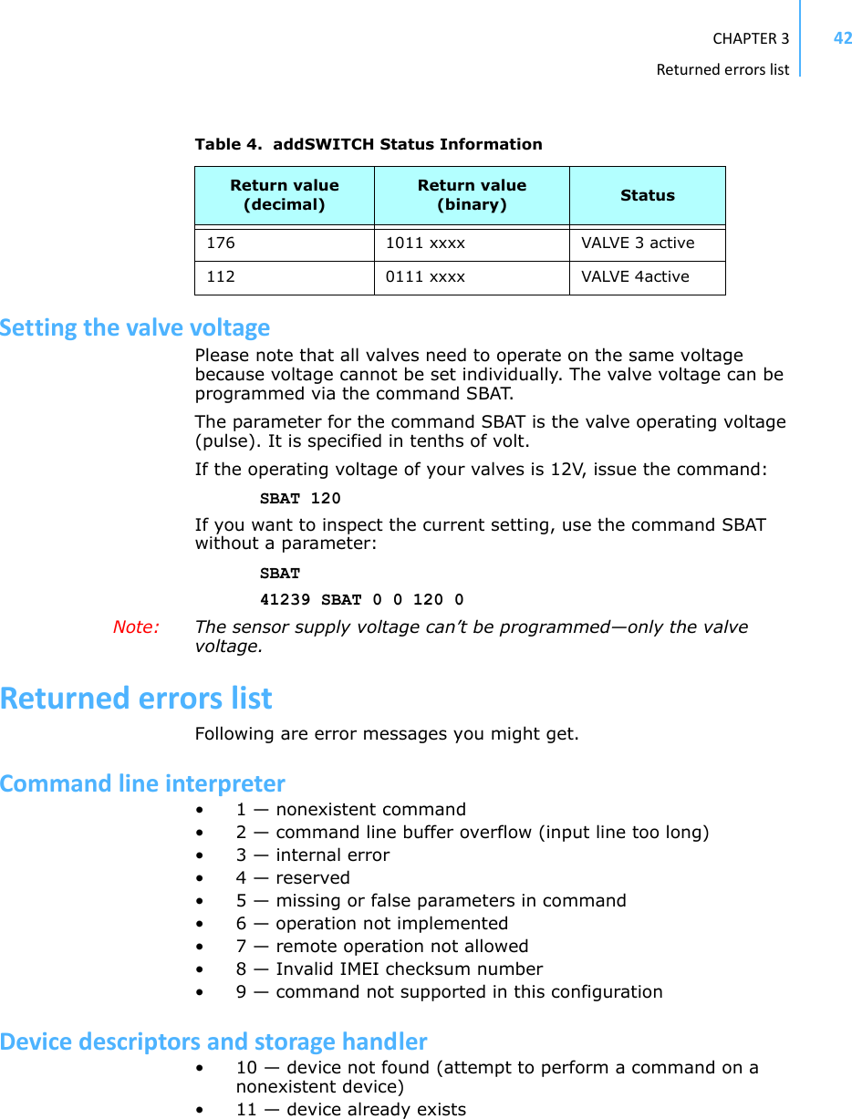
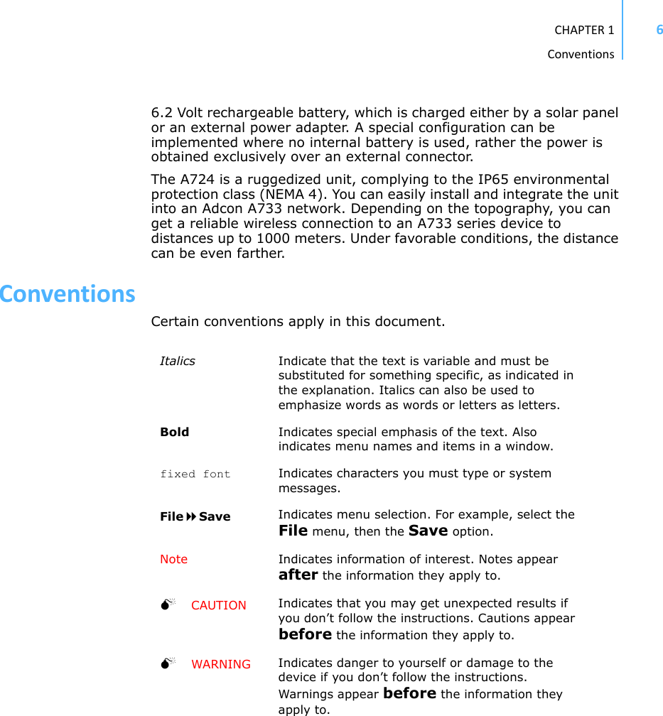
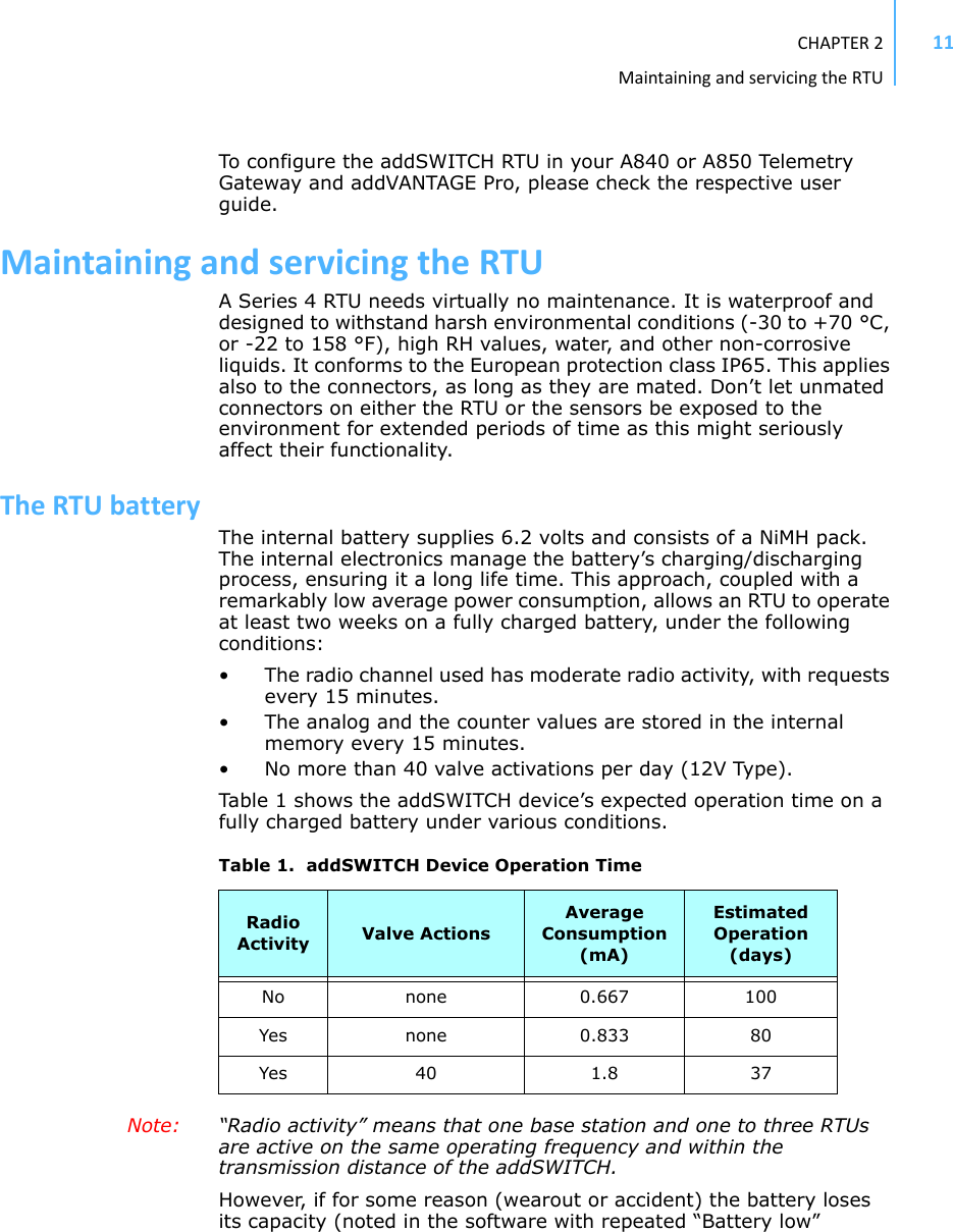
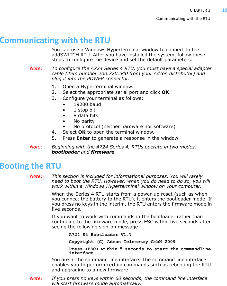
![CHAPTER3Usingterminalcommands31REMARKS GET/SET.REMOTE Yes, SET only.EXAMPLE ID 455741239 ID 0#ID4557 ID 4557 0#INFODESCRIPTION Returns various status information.PARAMETERS None.RETURNS A list of a device’s internal variables:ID INFO rf_in rf_out date time ver clk stack cop batt temp days_uptime hr:min_uptime rssi pmp_low pmp_high type slot samples po err_level#The formats for the above parameters are as follows:•rf_in and rf_out as a decimal •date as dd/mm/yyyy•time as hh:mm:ss•ver as x.x•clk, stack, and cop as decimal; they represent internal housekeeping parameters: the A724 uses cop to number watchdog occurrences, but clk and stack are currently undefined•batt as battery level using the standard voltage conversion equation (0 is 0 volts, 255 is 20 volts)•temp as internal temperature in the the A724 housing, which is device dependent. The precision of the sensing element is low (±2°C), but it is sufficient for battery power management (charge/discharge). To compute the actual value (in °C), the following equation must be used:•days_uptime in days; together with hr:min_uptime, it represents the amount of time the device is up without a reset or watchdog•hr:min_uptime in hours:minutes format•rssi as decimal; it is the value programmed with the RSSI command Temp °C[]internalTemp 400⋅255------------------------------------------------- 6 8–=](https://usermanual.wiki/Ott-Hydromet-Business-Unit-Adcon-Telemetry/A724-S4/User-Guide-1160728-Page-31.png)