Ott Hydromet Business Unit Adcon Telemetry A724-S4 Telemetry transceiver User Manual A724S4 User Manual
Adcon Telemetry GmbH Telemetry transceiver A724S4 User Manual
User Manual

A724Series4addSWITCH
UserGuide
SMARTWIRELESSSOLUTIONS

Proprietary Notice
The Adcon logo, Adcon Telemetry, Smart Wireless Solutions, the A720, A724 and A730 series,
addIT, addSWITCH, addWAVE, the A840 and A850 series and Telemetry Gateway, AgroExpert,
addVANTAGE®, addVANTAGE Lite and addVANTAGE Pro are trademarks or registered
trademarks of Adcon Telemetry GmbH.
Neither the whole nor any part of the information contained in this publication may be
reproduced in any material form except with the prior written permission of Adcon
Telemetr y G m b H .
This publication is intended only to assist the reader in the use of the product. Adcon
Telemetry GmbH shall not be liable for any loss or damage arising from the use of any
information in this publication, or any error or omission in such information, or any incorrect
use of the product.
Document Release 2.0, July 2009
Copyright ©2001-2009 by Adcon Telemetry GmbH.
All rights reserved.

3
Contents
Chapter 1.Introduction ____________________________________5
AbouttheA724Series4addSWITCH __________________________5
Conventions _____________________________________________6
Chapter 2.UsingtheaddSWITCH ____________________________7
Openingthepackages _____________________________________7
InstallingtheRTU _________________________________________8
FieldInstallation _______________________________________9
MoreabouttheLEDtool _______________________________10
TheaddTIMERextensionforaddVANTAGEPro5.3andnewer __10
MaintainingandservicingtheRTU __________________________11
TheRTUbattery ______________________________________11
Replacingthebattery __________________________________12
Chapter 3.PerformingAdvancedFunctions ___________________15
Understandingconnectors _________________________________15
TheRTUconnector ____________________________________15
ThePOWERConnector _________________________________16

Contents 4
TheVALVEConnector _____________________________________17
CommunicatingwiththeRTU ______________________________19
BootingtheRTU _________________________________________19
FirmwareMode ______________________________________20
UpgradingtheFirmware___________________________________20
Serialcommunicationprotocol _____________________________23
Generalformatofacommand ___________________________23
Generalformatofananswer ____________________________24
Usingterminalcommands _________________________________24
Commandsforcontrollingthevalves_________________________40
Switchingthevalves ___________________________________40
Readingstatusinformation______________________________41
Settingthevalvevoltage _______________________________42
Returnederrorslist_______________________________________42
Commandlineinterpreter ______________________________42
Devicedescriptorsandstoragehandler ____________________42
Realtimeclock _______________________________________43
Radiointerface _______________________________________43
Notifications _________________________________________43
Specifications ___________________________________________44
Index _________________________________________________ 47

5
Chapter 1.Introduction
This manual explains the hardware aspects of Adcon’s A724 Series 4
addSWITCH remote telemetry units, including installation issues and
certain parameter configurations. The manual has the following
chapters:
•Introduction, which gives some general information and
document conventions.
•Using the addSWITCH, which details the installation and use of
the remote telemetry unit.
•Performing Advanced Functions, which discusses connectors and
controllers and provides other information for advanced users.
•Specifications, which describes operating parameters for the
devices.
AbouttheA724Series4addSWITCH
The A724 Series 4 addSWITCH™ remote telemetry unit (RTU) is a
low-power, short-range telemetry device that can sample four pulse
counter inputs and one analog input, and control two irrigation valves
of the latching solenoid type.
The frequency of operation is in the 432 to 470 MHz range, making it
adaptable to most radio communication regulations in the world. The
output power is 10 mW, while the modulation is narrow-band FM (12.5
or 25 kHz channel spacing).
Due to its construction as well as to the software controlling it, the
power consumption is extremely low. The unit operates off an internal

CHAPTER1
Conventions
6
6.2 Volt rechargeable battery, which is charged either by a solar panel
or an external power adapter. A special configuration can be
implemented where no internal battery is used, rather the power is
obtained exclusively over an external connector.
The A724 is a ruggedized unit, complying to the IP65 environmental
protection class (NEMA 4). You can easily install and integrate the unit
into an Adcon A733 network. Depending on the topography, you can
get a reliable wireless connection to an A733 series device to
distances up to 1000 meters. Under favorable conditions, the distance
can be even farther.
Conventions
Certain conventions apply in this document.
Italics Indicate that the text is variable and must be
substituted for something specific, as indicated in
the explanation. Italics can also be used to
emphasize words as words or letters as letters.
Bold Indicates special emphasis of the text. Also
indicates menu names and items in a window.
fixed font Indicates characters you must type or system
messages.
FileSave Indicates menu selection. For example, select the
File menu, then the Save option.
Note Indicates information of interest. Notes appear
after the information they apply to.
CAUTION Indicates that you may get unexpected results if
you don’t follow the instructions. Cautions appear
before the information they apply to.
WARNING Indicates danger to yourself or damage to the
device if you don’t follow the instructions.
Warnings appear before the information they
apply to.

7
Chapter 2.UsingtheaddSWITCH
The A724 Series 4 addSWITCH remote telemetry unit (RTU) is part of
the A7xx series. For testing purposes, you should have an A840 or
A850 Telemetry Gateway including the A440 Wireless Modem installed
before you install the A724 Series 4 RTU. For information about
installing the A840 or A850, refer to the device’s user’s guide.
Openingthepackages
The addSWITCH RTU package contains the A724 Series 4 RTU, a valve
connector cable, and a ring clamp. If ordered, the following items
come in separate packaging:
• A solar panel with ring clamp
• A set of aluminum poles
•An LED tool
• Sensors and cables, one box per sensor, and one or several cable
ties in each sensor box
Make sure you have received all the equipment and read through the
instructions that follow. When you are sure you understand them, you
are ready to install your RTU.

CHAPTER2
InstallingtheRTU
8
Figure 1 shows the front view of an addSWITCH RTU.
Figure 1. addSWITCH RTU
Note: If you turn or manipulate the Gore Prevent element, the unit’s IP65
environmental protection could be affected.
InstallingtheRTU
The following restrictions apply:
• In general, the typical “line-of sight” distance the RTU can
communicate is 1 km (0.6 miles). This is valid if both the RTU and
its partner device are mounted on a 3 m mast (9 ft.). The results
can vary under different conditions and you could achieve higher
or lower distances.
• As with all wireless communication devices, the higher the
transmitter is installed, the better the communication will be.
VALVE
CONNECTOR
ANALOG
ANDCOUNTER
INPUTS
TO
SOLAR
PANEL
GORE PREVENTTM

CHAPTER2
InstallingtheRTU
9
FieldInstallation
It is relatively easy to install RTUs in the field. You can perform a
connectivity check with an LED tool, an example of which is shown in
Figure 2.
Figure 2. LED Tool
Note: The LED tool is a blind plug to be connected to the POWER connector.
Follow these steps to install Adcon’s RTU in the field:
1. Review the installation area and choose the best site.
2. Perform a connectivity check using the LED tool:
a. Insert the LED tool into the POWER connector and wait up to
10 seconds. If the unit connects to at least one station (or a
base station), it will light up the LED for about four seconds.
b. Keep observing the LED tool and, after another several
seconds, the LED will blink one or more times (the number of
blinks indicates the number of stations it has contacted).
3. Unpack the pole set.
4. Using a sledge hammer, drive the base pole (pointed tip) into the
ground until it is securely and tightly seated. To prevent damage
to the top of this pole make sure to put a protective cap on top of
it prior to pounding it in. Such a pole pounder can be ordered
from your Adcon distributor (item number 900.000.014).
5. Using a ring clamp, fasten the solar panel onto the aluminum
pole. Make sure that the panel is facing south (north if you are
located in the southern hemisphere) and out of the way of the
RTU.
Note: The solar panel can be mounted under or behind the RTU, but be sure
that the RTU does not shadow the panel.
6. Fasten the RTU to the top of the pole using another ring clamp.
Adcon recommends that you perform another connectivity test, if
you can, to check the positioning of the device.
WARNING If you turn the fastening screws too tightly, you might damage the
plugs.
7. Attach the sensors to the INPUT connectors and the solar panel to
the POWER connector by turning the plugs’ fastening screws
clockwise until secure.
8. Secure the extra length of the sensor cables to the pole with UV
resistant cable ties.

CHAPTER2
InstallingtheRTU
10
This completes the installation of your addSWITCH RTU. If one of the
I/O connectors is left unused, use the cap provided to protect it
against moisture and dust. Be sure to make a note of the following
information because you’ll need it when you configure the device in
the software:
• Serial number of each RTU and location
• Type of sensors connected to which port of each RTU
MoreabouttheLEDtool
The LED tool allows you to rapidly check the status of an RTU. After
you insert the LED tool into the POWER connector, the unit waits up to
two seconds and then sends a broadcast frame. If a nearby listening
station or receiver decodes the frame, it will answer—this may take up
to 10 seconds. When an answer is received, the LED tool lights up for
about four seconds. After another few seconds, the LED lights up one
or more times, depending on the number of stations/receivers that
answered to its broadcast frame.
In addition, the LED always blinks briefly at half-second intervals to
indicate that the unit is alive and the internal battery has enough
energy to operate. If the blinking interval lengthens to two seconds,
the battery has become undercharged (that is, under 5.6 volts but
over 5.2 volts)—this is called the misery state. In this state, an RTU
reduces its activities to a minimum. The radio unit is switched off, the
sensor sampling ceases, and no data is stored in the internal memory.
Only the internal real-time clock is maintained and the power
management functions are performed.
If the battery level drops below 5.2 volts, the system switches
completely off, effectively decoupling itself from the battery in order to
protect it. In this case the LED tool stays permanently off. An RTU in
such a situation will restart only after connecting it to an external
power supply (even a solar panel under low light conditions).
Note: New addSWITCH RTUs are delivered with their internal batteries
unformatted, meaning they have never been charged before. You
should install them only on sunny days. The battery will be fully
charged after two consecutive sunny days, but you should get an LED
light-up after several minutes of charging in the sunlight. You can also
charge the unit with Adcon’s RTU charger (item number
200.733.550).
TheaddTIMERextensionforaddVANTAGEPro5.3andnewer
In order to fully exploit the capabilities of the A724 addSWITCH, we
have developed the addTIMER extension for addVANTAGE Pro. This
extension lets you define several irrigation shifts by determining their
start time and their run time in minutes. By assigning a valve to a
predefined shift, addTIMER will automatically open and close each
addSWITCH without further intervention by the user. This routine will
continue until you modify or halt the sequence.

CHAPTER2
MaintainingandservicingtheRTU
11
To configure the addSWITCH RTU in your A840 or A850 Telemetry
Gateway and addVANTAGE Pro, please check the respective user
guide.
MaintainingandservicingtheRTU
A Series 4 RTU needs virtually no maintenance. It is waterproof and
designed to withstand harsh environmental conditions (-30 to +70 °C,
or -22 to 158 °F), high RH values, water, and other non-corrosive
liquids. It conforms to the European protection class IP65. This applies
also to the connectors, as long as they are mated. Don’t let unmated
connectors on either the RTU or the sensors be exposed to the
environment for extended periods of time as this might seriously
affect their functionality.
TheRTUbattery
The internal battery supplies 6.2 volts and consists of a NiMH pack.
The internal electronics manage the battery’s charging/discharging
process, ensuring it a long life time. This approach, coupled with a
remarkably low average power consumption, allows an RTU to operate
at least two weeks on a fully charged battery, under the following
conditions:
• The radio channel used has moderate radio activity, with requests
every 15 minutes.
• The analog and the counter values are stored in the internal
memory every 15 minutes.
• No more than 40 valve activations per day (12V Type).
Table 1 shows the addSWITCH device’s expected operation time on a
fully charged battery under various conditions.
Note: “Radio activity” means that one base station and one to three RTUs
are active on the same operating frequency and within the
transmission distance of the addSWITCH.
However, if for some reason (wearout or accident) the battery loses
its capacity (noted in the software with repeated “Battery low”
Table 1. addSWITCH Device Operation Time
Radio
Activity Valve Actions
Average
Consumption
(mA)
Estimated
Operation
(days)
No none 0.667 100
Yes none 0.833 80
Yes 40 1.8 37

CHAPTER2
MaintainingandservicingtheRTU
12
messages), it must be replaced. Make sure though, that the problem
is really due to the battery and not to a defective or dirty solar panel.
Adcon highly recommends that you frequently check and clean your
solar panels. Rain and dust can cover the solar panel’s surface with a
thin layer of dirt, effectively reducing its power output. Surrounding
vegetation can also lower panel efficiency.
Replacingthebattery
If you have verified that the battery needs to be replaced, follow these
steps to do so:
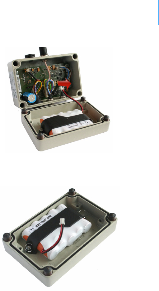
1. Open the lid by unscrewing the four screws in the corners of the
RTU, then remove the lid as shown in Figure 3. Make sure to use
a 3mm Allen key to prevent damage to the screw heads.
Figure 3. Removing the addSWITCH Lid
2. The battery pack is connected to the electronics board by means
of a PCB connector. Remove the battery pack’s plug from the PCB
connector, as shown in Figure 4.
CHAPTER2
MaintainingandservicingtheRTU
13
Figure 4. Unplugging the PCB Connector
3. Unscrew the two nuts of the plastic cover that holds the battery
pack in place, then remove the cover. Figure 5 shows the battery
pack inside the RTU.
Figure 5. Battery Pack
4. Remove the battery pack and replace it with a new one
(obtainable from Adcon).
5. Replace the plastic cover and fasten the two nuts.
6. Insert the battery plug into the PCB connector.
WARNING Be sure to mount the rubber gasket properly, so that the unit’s IP65
environmental protection is not affected. You must also be sure to not
squeeze the battery cable.
7. Mount the lid back, taking care that the rubber gasket sealing the
box is correctly in place and free of dirt and soil.

CHAPTER2
MaintainingandservicingtheRTU
14
8. Screw the four cover screws back in, applying a moderate force.

15
Chapter 3.PerformingAdvanced
Functions
With the appropriate knowledge, you can configure addSWITCH
devices in the field by using a hyperterminal window. To configure the
RTU, you will need a special serial cable adapter (not supplied, but
available from your Adcon distributor).
CAUTION Do not try to configure your RTUs if you are not sure what to do—the
unit might not communicate with the remote measuring station or
function with the addVANTAGE software.
WARNING Tampering with parameters for the RTUs may void your warranty or
damage the device. In general, the commands described in this
chapter are intended for technical support staff and users with a great
deal of highly technical hardware and software experience.
In the system architecture, the base station and RTU are both
considered to be nodes. The base station is called the master node, or
master, while the RTU is called the slave node, or slave.
Understandingconnectors
The addSWITCH devices have cable attachments called connectors.
The connector type determines how the device communicates with the
sensors or the computer.
TheRTUconnector
The A724 Series 4 addSWITCH RTU uses a non-standard 7-pin sensor
I/O connector (model Binder 702 and 712 series or equivalent). The

CHAPTER3
Understandingconnectors
16
connector contains four pulse counter inputs, one analog input, and a
sensor supply voltage output. Figure 6 illustrates the individual pins of
an I/O connector.
Figure 6. Pins on the I/O Connector (Top View)
ThePOWERConnector
The RTU also has a POWER connector, which allows for:
• External supply (battery or any DC source from 5.6 to 10 volts)
• External charge supply (either a solar panel or an AC adapter) if
an internal rechargeable battery is used
• Communication over serial lines, at 19200 baud
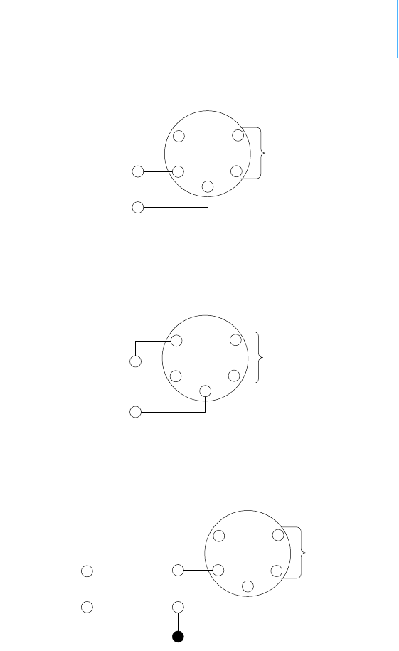
Figure 7 illustrates the connections available at the POWER connector.
Figure 7. A724 POWER Connector (Top View)
WARNING The serial line is 3-volt CMOS compatible; therefore, a special adapter
cable must be used to reach the RS-232 levels. Also, if an external
battery is used, the internal battery must be disconnected.
You might want to use the POWER connector with something other
than the standard configuration. For example, if you want to connect
an external battery to the RTU, disconnect the internal battery and
use the configuration shown in Figure 8.
SBAT
CNT3 CNT0
CNT1
AN0
GND
CNT2
7
3
6
5
1
2
4
Ext
Power
TxD
RxD
Ground
Battery
5
2
4
1
3
CHAPTER3
TheVALVEConnector
17
Figure 8. A724 Connection with External Battery
If you want to use the internal battery with a different power supply
(charger) than the provided solar panel, disconnect the solar panel
and use the configuration shown in Figure 9.
Figure 9. A724 Connection with External Power Supply
And if you want to use an external battery with a different power
supply (charger) than the provided solar panel, disconnect the internal
battery and solar panel and use the configuration shown in Figure 10.
Figure 10. A724 Connection with External Battery and Power Supply
TheVALVEConnector
The VALVE connector (Figure 11) is used to connect up to four
latching solenoids. The connector is a 6-pin SWITCHCRAFT connector
(EN3P6F, counterpart is the EN3C6M).
The A724 comes with a 0.5m cable with flying ends. A standard
insulating screw joint can be used to connect the solenoid. It is up to
you to protect this insulating screw joint for outdoor usage.
Short
Battery
5
2
4
1
3
+
-
(5.6 to 10 Volt)
Short
Charger
5
2
4
1
3
+
-
(9 to 10 Volt,
100 to 300 mA)
Short
Battery
5
2
4
1
3
+
-
(5.6 to 10 Volt)
Charger
(must fit the
Battery)
+
-

CHAPTER3
TheVALVEConnector
18
Figure 11. The Valve Connector
WARNING Do not use only one COM wire for all valves.
Connect the positive terminals (commonly red) of the valve to the
corresponding Valve1-4 pins and the negative terminals (commonly
black) to the COM pins.
WARNING Be sure to check the cabling, otherwise one or more valves will switch
to ON state when the RTU enters misery mode or upon a reset of the
RTU.
Note: COM wires brown and green should be used for valve1 and valve2,
pink and blue for valve3 and valve4.
The cable colors of your valve may differ from this scheme. Please
consult the manufacturer of your valves.
Note: When the polarity is reversed, the valve operation is also reversed.
The user can check the correct cabling with the power up sequence of
the A724.
WARNING Be sure to check the cabling for shortcuts because the RTU can be
damaged when it is operated with improper connections.
When the A724 starts up (e.g. the battery is connected), it
immediately sends OFF commands to all valves (sequential).
Valve1
COM
Valve3
Valve2
Valve4
COM
1
4
6
2
5
3
Table 2. Valve Connector Signals and Cable Colors
Signal Switchcraft pin Color
Valve1 1 white
COM 2 brown, green
Valve2 4 yellow
Valve3 5 gray
COM 3 pink, blue
Valve4 6 red

CHAPTER3
CommunicatingwiththeRTU
19
CommunicatingwiththeRTU
You can use a Windows Hyperterminal window to connect to the
addSWITCH RTU. After you have installed the system, follow these
steps to configure the device and set the default parameters:
Note: To configure the A724 Series 4 RTU, you must have a special adapter
cable (item number 200.720.540 from your Adcon distributor) and
plug it into the POWER connector.
1. Open a Hyperterminal window.
2. Select the appropriate serial port and click OK.
3. Configure your terminal as follows:
• 19200 baud
•1 stop bit
• 8 data bits
•No parity
• No protocol (neither hardware nor software)
4. Select OK to open the terminal window.
5. Press Enter to generate a response in the window.
Note: Beginning with the A724 Series 4, RTUs operate in two modes,
bootloader and firmware.
BootingtheRTU
Note: This section is included for informational purposes. You will rarely
need to boot the RTU. However, when you do need to do so, you will
work within a Windows Hyperterminal window on your computer.
When the Series 4 RTU starts from a power-up reset (such as when
you connect the battery to the RTU), it enters the bootloader mode. If
you press no keys in the interim, the RTU enters the firmware mode in
five seconds.
If you want to work with commands in the bootloader rather than
continuing to the firmware mode, press ESC within five seconds after
seeing the following sign-on message:
A724_S4 Bootloader V1.7
Copyright (C) Adcon Telemetry GmbH 2009
Press <ESC> within 5 seconds to start the commandline
interface...
You are in the command line interface. The command line interface
enables you to perform certain commands such as rebooting the RTU
and upgrading to a new firmware.
Note: If you press no keys within 60 seconds, the command line interface
will start firmware mode automatically.

CHAPTER3
UpgradingtheFirmware
20
In bootloader mode, the command line interface’s prompt is the
character >. Therefore, to reboot the RTU just type the following after
you see the > prompt:
reboot
An alternative way to boot the RTU is to disconnect the battery and
after a few seconds reconnect it.
For a list of the available commands, type Help at the > prompt.
Available commands:
upgrade [baudrate] ... upgrade from Y-modem download
version ... show the version of the bootloader
state ... show the board state
reboot [id] ... reboot the RTU
firmware ... start the firmware
help ... display this help text
Note: For some commands, such as the reboot command, you can supply
the ID of the RTU.
FirmwareMode
When you enter firmware mode, the following message is displayed in
the Hyperterminal window:
Checking firmware ... firmware found!
41239 0
#
The bootloader scans the program memory for a valid firmware by
testing the checksum, which takes a moment. If everything is correct,
the "firmware found!" message appears.
A moment after the firmware is found, the RTU’s identification number
(for example, 41239) and error code (in this example, 0) are
displayed. After another moment, the firmware mode’s command line
interface prompt is displayed (#).
If you need to return to bootloader mode when you’re in firmware
mode, enter the Reboot <ID> command at the prompt.
See “Using terminal commands” on page 24 for commands available
in firmware mode.
UpgradingtheFirmware
Note: This section is included for informational purposes. You will rarely
need to upgrade the firmware. However, when you do need to do so,

CHAPTER3
UpgradingtheFirmware
21
you will work within a Windows HyperTerminal window on your
computer.
Before upgrading the firmware, you must reboot the RTU to access the
bootloader mode’s command line interface. Follow the procedure
described under Booting the RTU to get into the bootloader.
Before you start the upgrade, it is very important that you copy the
firmware image to the hard drive of the computer you use in the field.
You also need to know which version of the bootloader you are
running. You can determine the version any of the following ways:
• Look at the bootloader’s signon message when you start it.
• At the bootloader mode’s > prompt, enter the Version
command.
• In firmware mode, enter the Reboot <ID> command and look at
the signon message.
• In firmware mode, enter ver at the # prompt.
Now you’re ready for the upgrade.
1. At the ’>’ prompt, enter the following command:
upgrade 115200
The upgrade process starts.
Note: For pre-1.7 versions of the bootloader, omit the speed parameter
(115200 used to be the default). For 1.7 and later versions, include
the 115200 baudrate parameter. If you do not specify a baudrate, the
upload runs at the default 19200 baudrate.
Change the baudrate of your terminal to '115200' and
hit <Return> to start flashing.
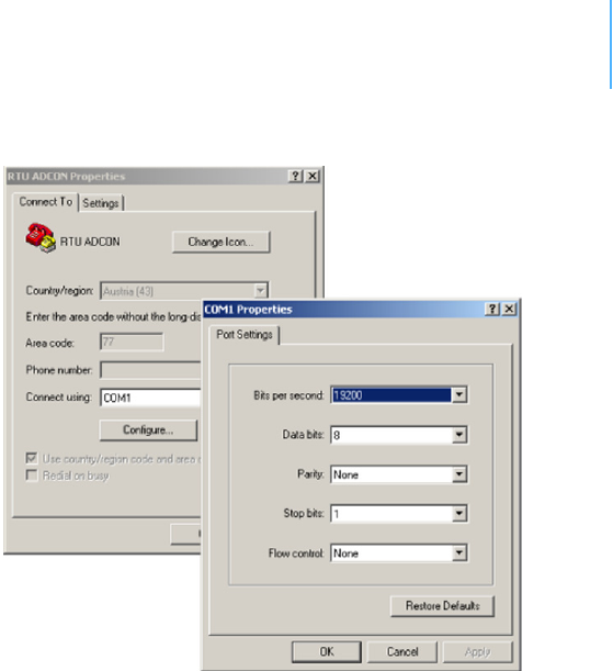
2. Select FileProperties to open the hyperterminal’s Properties
dialog.
3. Select a com port for the Connectusing field.
Note: If your bootloader is version 1.7 or later and you used the > update
command rather than the > update 115200 command, you can skip
Step 4 through Step 6. The bootloader will use a baud rate of 19200.
4. Click the Configure button to display the com port’s Properties
dialog (Figure 12 shows a COM1 com port).
CHAPTER3
UpgradingtheFirmware
22
Figure 12. Hyperterminal and Com Port Properties Dialogs
5. In the Bitspersecond field, select 115200.
6. Select OK in the com port’s Properties dialog to close it.
7. Select OK in the hyperterminal’s Properties dialog to close it.
8. Back in the hyperterminal window, press Enter to continue the
upgrade.
---------------------------------------------------
The current firmware image must be erased for the
upload.
If you continue now, you *MUST* upload a valid
firmware image for an A724_S4!
Continue? [y/n]:
WARNING When you continue with the upgrade process, any existing firmware
image in the RTU’s flash memory will be erased! You must supply a
valid image for upload or the RTU will have only bootloader
capabilities (that is, it will have no radio capabilities).
9. Enter Y to continue the upgrade.
The bootloader starts sending the letter C (for connect)
Starting flash blankcheck and erase process. . . done
---------------------------------------------------
Start the Y-modem upload now!
Starting CCCCC
CHAPTER3
Serialcommunicationprotocol
23
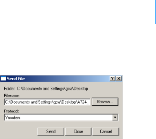
10. From the hyperterminal window’s menu bar, select TransferSend
File to display the dialog shown in Figure 13.
Note: You must start the image upload within 60 seconds or a timeout will
occur.
Figure 13. Dialog to Upload Firmware Image
11. Browse to and select the firmware image.
12. Select the Ymodem Protocol and click Send.
13. To start the new firmware, enter the following command:
firmware
Serialcommunicationprotocol
This protocol is based on a master sending commands and a node
answering. The whole communication is conducted in plain ASCII, as
strings, and numbers are represented in decimal format. All
commands are terminated with a CR/LF combination. All responses
(answers) are terminated with the # character.
Generalformatofacommand
The commands have the following format:
ID Command Param1 Param2 ... ParamN
•ID is the destination device. If you include an ID as part of a
command, the node checks whether ID=ownID. If it does, the
node executes the command on itself. If the ID is not the node’s
ID, the node executes the command on a remote device, if such
an ID exists. If the ID is missing, this implies that the command
is addressed locally.
Note: Not all the commands can be relayed remotely.
•Command is the command proper, which can be composed of a
variable string of characters (for example, SLOT). Each node can
implement a set of commands depending on the functionality of
the node itself. However, as a minimum requirement, a node
recognizes the CMDS command, which returns a list with the
commands accepted by the node.

CHAPTER3
Usingterminalcommands
24
•Param1 Param2 ... ParamN represent the parameters, which
are command dependent. If you type no parameters when you
issue a command, it is the equivalent of querying for information
(the GET version of a command). If you type parameters, you
are issuing the SET version of a command and are setting the
command to the parameters you typed.
Generalformatofananswer
The answers have the following format:
ID Command Result1 Result2 ... ResultN ErrResult #
•ID is the answering device. If a command was further routed, it is
the ID of the end device. The answer must always contain the ID
on return.
•Command is the string representing the original command. It is
supplied so that a master can distinguish between the answers it
is waiting for, and out-of-band notifications (which may come, for
example, over the radio port of a node). As with the ID, the
command name must always be supplied.
•Result1 Result2 ... ResultN are the result values returned
by the remote node. If the ErrResult is not zero, all other
possible characters and/or strings until the end of the line might
be ignored.
•ErrResult shows whether the command was successfully
executed. If this value is 0, the command was successfully
executed. If this value is other than 0, the command failed. The
number may further indicate the error type. (See also “Returned
errors list” on page 42.)
The answer string may contain any number of spaces or CR/LF
characters between its components. However, after the terminator
(#), no other characters are allowed.
Usingterminalcommands
The addSWITCH A724 firmware is basically the same as the addIT
A723 Series 4, except for the following items:
• new device type: A724_S4
• digital ports are used internally for valve control (bit 4-7)
Following is a list of available commands and an explanation of their
use.
Note: You can type uppercase or lowercase characters because the
commands are not case sensitive.
ANLG
DESCRIPTION Sets/returns the various parameters for the analog subsystem (for
example, the sampling/averaging method).

CHAPTER3
Usingterminalcommands
25
PARAMETERS A control byte specifying the command and the analog input channel
number the command is acting on. Please look into the A733 User
Guide for a complete command description.
RETURNS The current ANLG setting.
REMARKS For the A724 Series4, only one analog channel is available.
REMOTE Yes.
EXAMPLE # ANLG 64
41239 ANLG 0
# ANLG 0
41239 ANLG 0 4 0 0 0 0 0 0 0 0 0 0 0 0
#
ANRT
DESCRIPTION Sets/returns the analog signal routing configuration for RTUs earlier
than Series 4.
PARAMETERS See the manual for the appropriate pre Series 4 RTU.
RETURNS The current setting.
REMARKS Remote only. Support for pre Series 4 RTUs.
REMOTE Yes.
EXAMPLE 14446 ANRT
14446 ANRT 0 1 2 3 4 5 6 7 8 9 10 11 0
#
B
DESCRIPTION Sends a broadcast frame.
PARAMETERS None.
RETURNS A data block.
REMARKS After the device has sent the broadcast frame, it will listen for
answers. All valid answers will be listed with their IDs.
REMOTE Yes. A device getting this frame would have to wait for a random time
(2 to 10 seconds) before performing the actual broadcast; if no
terminal is active, no results will be listed. A list of stations heard, with
their RF levels, will be updated in the memory and will be available
whenever the BLST command is issued.
EXAMPLE B
41239 B 0
#42340 BA 0
#34781 BA 0

CHAPTER3
Usingterminalcommands
26
BLST
DESCRIPTION Lists the stations heard after the last broadcast command was issued.
PARAMETERS None.
RETURNS The date and time the broadcast was performed, the number of
stations heard, and a list with the heard stations’ IDs and their
respective RF levels.
REMARKS GET only.
REMOTE Yes. The remote version will list only the first nine stations heard.
EXAMPLE BLST
41239 BLST 08/05/2009 15:56:04 4
42340 235 255
34781 255 255
#
CALC
DESCRIPTION Sets/returns the settings for optional minimum and maximum values
for the analog input.
PARAMETERS Two 1-bit bitmasks. The first mask is used to enable minimum and the
second for maximum values.
RETURNS The current CALC setting.
REMARKS The masks are binary masks.
REMOTE No.
EXAMPLE # CALC 1 1
41239 CALC 0
# CALC
41239 CALC 1 1 0
#
CMDS
DESCRIPTION Returns a list of supported commands.
PARAMETERS None.
RETURNS A list of strings separated by spaces.
REMARKS GET only.
REMOTE No.
EXAMPLE CMDS

CHAPTER3
Usingterminalcommands
27
41239 cmds ANLG ANRT B BLST CALC DATA DATASDI DPE DYNSLOT
FDEV FREQ ID INFO MSTR PMP PORT ROUTE RSSI SBAT SLOT SST
TIME TYPE VER VERB XCONF XDATA XIMME 0
#
DATA
DESCRIPTION Retrieves data frames from RTUs earlier than Series 4.
PARAMETERS See the manual for the appropriate pre Series 4 RTU.
RETURNS A pre Series 4 data frame.
REMARKS Remote only. Support for pre Series 4 RTUs.
REMOTE Yes.
EXAMPLE 14446 DATA 14446 24/12/2008 16:00:00
14446 DATA 24/12/2008 16:00:00 21 37 235 255 15
0 0 0 0 89 2 0 350 0 0 0 0 0 0 2 504 1312 0 0
#
DATASDI
DESCRIPTION Retrieves SDI-12 data frames from RTUs earlier than Series 4.
PARAMETERS See the manual for the appropriate pre Series 4 RTUs.
RETURNS A pre Series 4 SDI-12 data frame.
REMARKS Remote only. Support for pre Series 4 RTUs.
REMOTE Yes.
EXAMPLE 14446 DATASDI 14446 24/12/2008 16:00:00
14446 DATA 24/12/2008 16:00:00 FIXME
#
DPE
DESCRIPTION Sets/returns the digital port event settings of a device.
PARAMETERS The first parameter is the 12-bit bitmask to specify the port bits that
will trigger a digital port event.
The second parameter is the timeout in seconds (1-65536). When the
timeout occurs without a port change on a configured port, a digital
port event will be enforced. This is useful for having regular port state
updates and additionally updates when the port state changes. Use 0
for the second parameter to turn off the timeout.
Note: A low timeout value will produce a lot of dataframes, which might
overload the radio channel transmission capacity!

CHAPTER3
Usingterminalcommands
28
RETURNS The current settings.
REMARKS GET/SET.
REMOTE Yes, via XCONF.
EXAMPLE This example shows a setup where a status change of one of
he valve ports will throw a digital port event.
Additionally, the state of the valves will be recorded
every 3600 seconds with a digital port event.
# dpe 240 3600
41239 dpe 0
# dpe
41239 dpe 240 3600 0
#
DYNSLOT
DESCRIPTION Sets/returns the dynamic slot switching function of the device. The
dynamic slot switching function checks whether the measurement
value of a given sensor matches the given condition, then switches
between two operating modes:
1—normal mode (when the condition is false and the lock timer is
zero)
2—execution mode (when the condition is true and the lock timer
is non-zero)
The rules for the mode switching are:
• When the condition becomes true the first time, exception mode
is entered and the lock timer is set.
• While the condition is true, the lock timer is set at every sample;
thus it does not reach zero.
• While the condition is false, the lock timer is decremented if not
already zero.
• When the lock timer reaches zero, normal mode is entered.
• The SLOT settings are changed only when the mode changes.
Thus, the RTU enters exception mode whenever a sample value
matches the condition, and stays there until the sample value does
not match the condition for at least the given lock time (this prevents
excessive wear of the EEPROM due to jitter in the measurement
value).
PARAMETERS 1—sensor type (0=none, 1=internal battery, 2=anlg, 3=port,
4=counter).
2—sensor address (channel number as in the ANLG and PORT
command).
3—limit type (0=above, 1=below, 2=out of range, 3=within range).

CHAPTER3
Usingterminalcommands
29
4—the limits (depending on limit type):
For type=0 /1—one limit.
For type=2/3—two limits.
Note: The limit values are raw adc values (0-2.5V=0-65535).
5—a bitmask specifying for which connector the SLOT value must be
changed (0=internal, 1..4=I/O-A..I/O-D, 5=Valves, 6=SDI-12).
6—lock time for the active state.
WARNING Timeout values lower than 3600 seconds can lead to an excessive use
of the data storage. This can reduce dramatically the lifetime of the
device.
7—SLOT value for exception state.
8—SAMPLE value for exception state.
9—SLOT value for normal state.
10—SAMPLE value for normal state.
RETURNS The actual setting, the lock timer value (0=inactive, 1-43200=active)
and the number of dynamic slot switches since power-on of the RTU.
REMARKS GET/SET.
REMOTE Yes.
EXAMPLE This example describes a DYNSLOT setup for:
• I/O-A (Input connector) cabling 1 (Analog channel 0)
• When value is greater than 1.25V (1.25V=32768)
• SLOT/SAMPLE will be altered on I/O-A (Input connector)
• Timeout will be 3600 seconds
• The exception SLOT/SAMPLE settings will be 900 15
• The normal SLOT/SAMPLE settings will be 900 15
# DYNSLOT 2 0 0 32768 0x02 3600 60 1 900 15
41239 DYNSLOT 0
# DYNSLOT
41239 DYNSLOT 2 0 0 32768 0x02 3600 60 1 900 15 0 0 0
#
FDEV
DESCRIPTION Formats the internal memory (might destroy all the data).
WARNING The chip configuration setting (first parameter of the command)
depends on the current hardware version and must not be altered.
Please contact our support team for further information.
PARAMETERS If the parameters are missing, the command will show the current
settings. To format the internal memory (all data will be lost) with the
current settings, use 0 as the first parameter. The storage

CHAPTER3
Usingterminalcommands
30
organization (only index size), can be optimized for your specific
application.
The first parameter for this command is the chip configuration and
second parameter is the index size.
The following EEPROM types are currently available:
• 3– 32Kbytes (e.g. model 25256, 1 device)
• 7– 64Kbytes (e.g. model 25256, 2 devices)
RETURNS Current setting.
REMARKS GET/SET.
REMOTE Yes, SET only.
EXAMPLE FDEV
41239 fdev 7 32+32 256..4096 1280/0 51200/0 0
# FDEV 7 1280
41239 fdev 0
#
FREQ
CAUTION Do not change the frequency of your device without reason: apart
from the fact that it might not communicate in the network anymore,
you might also violate the applicable radiocommunications laws in
your country. Depending on the destination country, some models
may also return an error message.
DESCRIPTION Sets/returns the operating frequency.
PARAMETERS The operating frequency and step (Hz), or none in the GET version.
RETURNS The actual frequency and step, in Hz.
REMARKS GET/SET.
REMOTE Yes, SET only.
EXAMPLE FREQ 433925000 25000
41239 FREQ 0
#
FREQ
41239 FREQ 433925000 25000 0
#
ID
DESCRIPTION Sets/returns the node’s ID.
PARAMETERS The node ID.
RETURNS The node ID.

CHAPTER3
Usingterminalcommands
31
REMARKS GET/SET.
REMOTE Yes, SET only.
EXAMPLE ID 4557
41239 ID 0
#
ID
4557 ID 4557 0
#
INFO
DESCRIPTION Returns various status information.
PARAMETERS None.
RETURNS A list of a device’s internal variables:
ID INFO rf_in rf_out date time ver clk stack cop batt temp
days_uptime hr:min_uptime rssi pmp_low pmp_high type slot
samples po err_level
#
The formats for the above parameters are as follows:
•rf_in and rf_out as a decimal
•date as dd/mm/yyyy
•time as hh:mm:ss
•ver as x.x
•clk, stack, and cop as decimal; they represent internal
housekeeping parameters: the A724 uses cop to number
watchdog occurrences, but clk and stack are currently
undefined
•batt as battery level using the standard voltage conversion
equation (0 is 0 volts, 255 is 20 volts)
•temp as internal temperature in the the A724 housing, which is
device dependent. The precision of the sensing element is low
(±2°C), but it is sufficient for battery power management
(charge/discharge). To compute the actual value (in °C), the
following equation must be used:
•days_uptime in days; together with hr:min_uptime, it represents
the amount of time the device is up without a reset or watchdog
•hr:min_uptime in hours:minutes format
•rssi as decimal; it is the value programmed with the RSSI
command
Temp °C[]
internalTemp 400⋅
255
------------------------------------------------- 6 8–=

CHAPTER3
Usingterminalcommands
32
•pmp_low and pmp_high are the programmed values with the PMP
command)
•type is used to represent the device type; the following types are
currently assigned:
— 0 for A730MD
— 1 for A720
— 2 for A730SD
— 3 for A720B
— 4 for A733
— 5 for A723
— 6 for A440
— 7 for A733GSM
— 8 for A731
— 9 for A732
— 10 for A740
— 11 for A740GSM
— 12 for A724
— 13 for A725
— 14 for A726
— 15 for A723_S4
— 16 for A724_S4
— 21 for A733GSM_S4
•slot and samples are the actual values programmed by means
of the SLOT command
•po is the power output of the device during the last frame sent
•err_level is the error value; 0 means no error
REMARKS GET only.
REMOTE Yes, GET only. The the A724 can issue the command both remotely
and locally.
EXAMPLE INFO
41239 INFO 0 80 08/05/2009 15:05:55 1.3 0 0 0 77 61 7 1:46
100 65 72 16 60 0 21 0
#
MSTR
DESCRIPTION Sets/returns the master receiver setting, which is used for delivery of
notifications.
PARAMETERS The ID of the master receiver.
RETURNS The current master setting.
REMARKS MSTR is used for notifications delivery only, not for time
synchronization.
REMOTE No.

CHAPTER3
Usingterminalcommands
33
EXAMPLE # MSTR 43
41239 MSTR 0
# MSTR
41239 MSTR 43 0
#
PMP
DESCRIPTION Sets/returns the node’s Power Management Parameters (switches the
battery charge on/off).
PARAMETERS The lower (switch on) and the higher limit (switch off), both in volts x
10. Standard Values are 65 (for 6.5 Volts) for switch on and 72 (for
7.2 Volts) for switch off, for a standard 6.2 Volt NiMH battery. From
these values, other thresholds are internally computed.
RETURNS The lower (switch on) and the higher limit (switch off), both in volts x
10.
REMARKS GET/SET.
REMOTE Yes, SET only.
EXAMPLE PMP 65 72
41239 PMP 0
#
PMP
41239 PMP 65 72 0
#
PORT
DESCRIPTION A complex command acting upon the I/O ports of a device.
PARAMETERS A control byte specifying the command the bit of the port to command
is acting on, and two 16-bit parameters, depending on the control
byte. For some commands, the control byte or the paramaters (or
both) might be missing. Refer to the A733 User Guide for a complete
command description.
RETURNS The result depends on the control byte.
REMARKS For the A724 Series4, only one analog channel is available.
REMOTE Yes.
EXAMPLE For MFS:
# PORT 212 1 20
41239 PORT 212 0
#

CHAPTER3
Usingterminalcommands
34
ROUTE
DESCRIPTION Sets/returns the routing information of a device.
PARAMETERS None, or a route (with destination) containing up to eight
intermediaries. When just the destination ID is given, the route for
this device is deleted.
RETURNS The commands success or error code and the route table.
REMARKS GET/SET.
REMOTE No.
EXAMPLE For MFS:
# ROUTE 41240 43
41239 ROUTE 0
# ROUTE
41239 ROUTE
41240 43
0
#
RSSI
DESCRIPTION Sets/returns the Relative Signal Strength Indicator threshold at which
the RF receiver must wake up.
PARAMETERS The threshold value. For the A724 Series 4, it can take values from 0
to 255; it is typically factory set to 100.
RETURNS The instant RSSI value and the programmed threshold.
REMARKS GET/SET.
REMOTE No.
EXAMPLE RSSI 50
41239 RSSI 0
#
RSSI
41239 RSSI 34 50 0
#
Note: The values of the RSSI threshold have no units, they are arbitrary.
RX
DESCRIPTION Switches the unit to permanent receive mode (for tuning purposes).
PARAMETERS None.
RETURNS Nothing.

CHAPTER3
Usingterminalcommands
35
REMARKS The system stops, and exits the command only when a key is pressed.
This command returns no message.
REMOTE No.
EXAMPLE RX
41239 RX 0
#
SBAT
DESCRIPTION Sets/returns the operating voltage for the valves .
PARAMETERS The operating voltage of the valves in tenths of volt.
RETURNS The current setting.
REMARKS See also: Setting the valve voltage on page 42.
REMOTE No.
EXAMPLE SBAT
41239 SBAT 0 0 120 0
#
SLOT
CAUTION Changing these parameters may adversely affect the ability of the
device to operate for extended periods under low sunlight conditions.
DESCRIPTION Sets/returns the node’s sampling interval and rate.
PARAMETERS The interval (10 - 43200) and rate (0 - 255). The interval represents
the time (in seconds) elapsed between two slots stored in the internal
memory, while the rate represents the numbers of samples used to
build the average that will be stored. No average will be calculated for
the internal and the SDI-12 sensors. A third parameter can be used to
set the SLOT/SAMPLE settings for a specific connector.
Note: Not all combinations of SLOT/SAMPLE are accepted due to the time
alignment feature of A724 Series 4 RTU.
RETURNS The interval and rate.
REMARKS GET/SET. The default interval is 900 (15 minutes) and rate is 3 (5
samples per 15 minutes).
REMOTE Yes, SET only.
EXAMPLE SLOT 900 15
41239 SLOT 0
#

CHAPTER3
Usingterminalcommands
36
SLOT
41239 SLOT 900 1 900 15 900 15 900 15 900 15 900 1 0 0 0
# slot 600 10
41239 slot 0
# slot
41239 slot 600 1 600 10 600 10 600 10 600 10 600 1 0 0 0
# slot 300 30
41239 slot 0
# slot
41239 slot 300 1 300 30 300 30 300 30 300 30 300 1 0 0 0
# slot 3600 200
41239 slot 0
# slot
41239 slot 3600 1 3600 200 3600 200 3600 200 3600 200 3600 1
0 0 0
#slot 900 3
41239 slot 0
# slot
41239 slot 900 1 900 3 900 3 900 3 900 3 900 1 0 0 0
# slot 60 2 2
41239 slot 0
# slot
41239 slot 900 1 900 3 60 2 900 3 900 3 900 1 0 0 0
#
SST
DESCRIPTION Sets/returns the sensor supply time of a device.
PARAMETERS The first parameter is the sensor supply time in seconds.
The second parameter specifies 0=parallel or 1=sequential
measurement. This parameter is not used for the A724 Series 4.
The third parameter addresses the channel (connector):
0— internal (can’t be modified)
1— I/O-A (INPUT)
2— I/O-B
3— I/O-C
4— I/O-D
5— Valves
6— SDI-12
Note: The A724 Series 4 supports only connector I/O-A, which is identical to
the INPUT connector. The other connector SST settings should be 0.
RETURNS Current configuration.
REMARKS GET/SET.
REMOTE Yes, SET only. For full control use XCONF.
EXAMPLE # SST 0
41239 SST 0

CHAPTER3
Usingterminalcommands
37
# SST
41239 SST 0 0 0 0 0 0 0 0 0 0 0 0 0 0 0
# SST 5 0 1
41239 SST 0
# SST
41239 SST 0 0 5 0 0 0 0 0 0 0 0 0 0 0 0
#
TIME
DESCRIPTION Sets/returns the real time clock.
PARAMETERS The actual time, or none in the GET version.
RETURNS The actual time as dd/mm/yyyy hh:mm:ss.
REMARKS GET/SET.
REMOTE No.
EXAMPLE TIME 10/10/2010 22:10:10
41239 TIME 0
#
TIME
41239 TIME 10/10/2010 22:10:10 0
#
TX
DESCRIPTION Switches the unit to transmit mode (for tuning purposes).
PARAMETERS None (sends an unmodulated carrier), 1 (sends a 1 kHz modulated
carrier), 0 (sends a 2 kHz modulated carrier) or 5 (sends a mixed 1 +
2 kHz modulated carrier).
RETURNS Nothing.
REMARKS The system stops, and exits the command only when a key is pressed.
This command returns no message.
REMOTE No.
EXAMPLE TX
41239 TX 0
#
TX 1
41239 TX 0
#
TX 5
41239 TX 0
#

CHAPTER3
Usingterminalcommands
38
TYPE
DESCRIPTION Requests the hardware type information of the device.
PARAMETERS None.
RETURNS The hardware type.
REMARKS GET only.
REMOTE No.
EXAMPLE TYPE
41239 TYPE A724_S4
#
VER
DESCRIPTION Requests the firmware version of the device.
PARAMETERS None.
RETURNS The current version.
REMARKS GET only.
REMOTE No.
EXAMPLE VER
15535 VER 1.3.0 0
#
VERB
DESCRIPTION Sets the verbosity level of the RTU. This command is used for
debugging only.
WARNING The RTU will consume a lot more power when the verbosity level is
greater than 0. This could discharge your battery and/or prevent from
proper operation.
PARAMETERS A verbosity level (0...255).
RETURNS Error code.
REMARKS SET only.
REMOTE No.
EXAMPLE # VERB 1
41239 VERB 0
VERB 1 # src=43 dest=9002 type=?
src=43 dest=9002 type=?
verb 0

CHAPTER3
Usingterminalcommands
39
41239 verb 0
#
XCONF
DESCRIPTION This command transmits command strings for commands (those that
are suited for this mode of operation) to the targeted RTUs. Allowed
commands are: CALC, DPE, DYNSLOT, MSTR, SBAT, SLOT, SST and
SDI.
PARAMETERS A command string.
RETURNS The replying string and error code.
REMOTE Yes.
EXAMPLE # 41240 XCONF SBAT
41240 XCONF SBAT 0 0 120 0
# 41240 XCONF CALC
41240 XCONF CALC 0 0 0
#
XDATA
DESCRIPTION Returns data stored for a certain device.
PARAMETERS XDATA requires a lot of parameters for specifying what to retrieve.
Please consult the A740 User Manual for detailed explanation of this
command. The output of the command is not intended to be human
readable.
RETURNS A data block.
REMOTE Yes, for a GET, but only one frame at a time.
EXAMPLE XDATA 0 8 0 255 1 0
41239 xdata 0 196 0x18
0x4A042CD0 1 0 0xF6 :0F0262645B3D
0x4A042CD0 1 1 0xF6 :0700000262640B40
0x4A042DFC 1 2 0xF6 :030000003C64
0x4A042CD0 1 3 0xF6 :030000026264
0x4A042CD0 1 4 0xF6 :030000026264
0x4A042CD0 1 5 0xF6 :F3026264
0
#
XIMME
DESCRIPTION Samples all inputs and immediately returns the sampled data.
PARAMETERS First parameter specifies the sample mode, which has to be 2 for raw
data. The second parameter sets the maximum packet size. If you
specify the third parameter, you can select a certain input connector.

CHAPTER3
Commandsforcontrollingthevalves
40
Note: Only sample mode 2 is supported on the A724 Series 4 RTU.
RETURNS A data block of io-port, raw adc and counter values.
REMARKS GET only. The command needs a certain delay to execute (for
example, for the standard SST setting this delay amounts to two
seconds). The delay is necessary to allow for the sensors to settle
after applying power to them.
REMOTE No.
EXAMPLE # ximme 2
41239 ximme
0 0 91 61 0 0
1 240 64 0 0 9
2 240 0 0 0 12
3 240 0 0 0 1890
4 240 0 0 0 19
5 240
0
#
The first column is the channel number. Channel 0 uses the internal
sensors such as temperature and battery voltage. Channels 1-4 are
the virtual connectors IO-A through IO-D. The four counter inputs of
the A724 Series 4 are mapped to virtual connectors IO-A through IO-
D, although the A724 Series 4 has only one sensor connector (INPUT).
Column 6 of channel 1-4 are the counter values. The analog input is
mapped to column 3 of channel 1. In the above example, the analog
value is 64 and counters 1-4 have a count of 9, 12, 1890, and 19
respectively. The actual valve state is displayed in column 2. The
decimal value 240 shows that all four valves are inactive
(high=inactive).
Note: The number 240 displayed in binary form is 11110000, which means
bits 7 to 4 are high.
Commandsforcontrollingthevalves
This section describes various commands you can use to control the
valves.
Switchingthevalves
The valves can be controlled by the following commands shown in
Tab l e 3 .

CHAPTER3
Commandsforcontrollingthevalves
41
n is the desired run-time in seconds (max. 65535, approximately 18h)
and d is the startup delay in seconds (max. 65535, approximately
18h, the recommended minimum is 1s).
WARNING Do not use any other commands described here to control the valves.
Readingstatusinformation
Using the PORT 0 command, the actual status can be read back. For
details on the returned value see Table 4.
Table 3. addSWITCH Commands
Requested action addSWITCH A724 command
Open Valve 1 for n
seconds
PORT 212 d n
Open Valve 2 for n
seconds
PORT 213 d n
Open Valve 3 for n
seconds
PORT 214 d n
Open Valve 4 for n
seconds
PORT 215 d n
Close Valve 1 (before time
n has elapsed)
PORT 164
Close Valve 2 (before time
n has elapsed)
PORT 165
Close Valve 2 (before time
n has elapsed)
PORT 166
Close Valve 2 (before time
n has elapsed)
PORT 167
Table 4. addSWITCH Status Information
Return value
(decimal)
Return value
(binary) Status
240 1111 xxxx idle
224 1110 xxxx VALVE 1 active
208 1101 xxxx VALVE 2 active

CHAPTER3
Returnederrorslist
42
Settingthevalvevoltage
Please note that all valves need to operate on the same voltage
because voltage cannot be set individually. The valve voltage can be
programmed via the command SBAT.
The parameter for the command SBAT is the valve operating voltage
(pulse). It is specified in tenths of volt.
If the operating voltage of your valves is 12V, issue the command:
SBAT 120
If you want to inspect the current setting, use the command SBAT
without a parameter:
SBAT
41239 SBAT 0 0 120 0
Note: The sensor supply voltage can’t be programmed—only the valve
voltage.
Returnederrorslist
Following are error messages you might get.
Commandlineinterpreter
• 1 — nonexistent command
• 2 — command line buffer overflow (input line too long)
• 3 — internal error
• 4 — reserved
• 5 — missing or false parameters in command
• 6 — operation not implemented
• 7 — remote operation not allowed
• 8 — Invalid IMEI checksum number
• 9 — command not supported in this configuration
Devicedescriptorsandstoragehandler
• 10 — device not found (attempt to perform a command on a
nonexistent device)
• 11 — device already exists
176 1011 xxxx VALVE 3 active
112 0111 xxxx VALVE 4active
Table 4. addSWITCH Status Information
Return value
(decimal)
Return value
(binary) Status

CHAPTER3
Returnederrorslist
43
• 12 — reserved
• 13 — no more space for descriptors (too many devices)
• 14 — no more records for the specified device
• 15 — temporary communication break, no more data (the last
request was not successful)
• 16 — timeout (the handler blocked or is busy)
• 17 — internal error
• 18 — attempt to insert a reserved device ID number (0 or 65535)
Realtimeclock
• 20 — incorrect time supplied (conversion to time_t was not
possible)
Radiointerface
• 30 — error at receive (CRC, etc.)
• 31 — unexpected frame received
•32 — wrong length
• 33 — reserved
• 34 — reserved
• 35 — timeout (remote device not responding)
• 36 — receiver busy (for example, just executing a polling series)
• 37 — time stamp of a frame is too far in the future
• 38 — general modem error
• 39 — “unknown modem” error
Notifications
• 40 — request to read notification when no notification is pending

44
Appendix.Specifications
The addSWITCH A724 Series 4 was intended to fulfill the specification
of the ETSI 300 220, Class I, Subclasses a and b, but other national
norms are similar to this (for example, the CFR 47, Part 90,
Subpart J).
Table 5 shows the main operational parameters of the A724.
Table 5. Operational Parameters
Parameter Min Typical Max Unit
Common
Supply 5.0 6.2 10.0 V
Operating Temperature -30 +70 °C
Relative Humidity 10 99 %
Class Protection IP65
Data Rate (using the onboard software modem) 1000 1500a2000 bps
Operating Frequency b432 470 MHz
Frequency Stability (-20 to +60 °C) ±1.5 kHz
Frequency Stability (-30 to +70 °C) ±2.0 kHz

APPENDIX 45
Receiver
Sensitivity (10 db S/N) -105 dBm
Image Frequency Attenuation (IF = 200kHz) 35 dB
Local Oscillator Leakage 2 nW
Adjacent Channel Attenuation 55 dB
RSSI Dynamic 90 dB
Operating Current (incl. onboard microcontroller)c65 mA
Transmitter (all measurements made on a 50 Ohm
resistive load)
Output Power ERP 10 dBm
Spurious Radiation (0 to 862 MHz) 2 nW
Spurious Radiation (862 MHz to 3.5 GHz) 200 nW
Adjacent Channel Power (12.5 kHz version) -32 dBm
Adjacent Channel Power (25 kHz version) -44 dBm
Occupied Bandwidth (12.5 kHz version) 8.5 kHz
Occupied Bandwidth (25 kHz version) 15 kHz
Operating Current (incl. onboard microcontroller) 50 mA
Counter Inputs Vil 00.5V
Counter Inputs Vih 2.5 3.3 V
Pulse Counter Input Frequency 50 Hz
Pulse Counter Resolution 16 bits
Valve Output Voltaged,e515V
Valve Output Pulse 100 ms
a. Data rate is content dependent.
b. This parameter represents the tuning range; the switching range may be limited in
the software to a narrower space (even to the extent of a single channel).
c. Continuous duty.
d. The energy stored in a 4700uF capacitor is fired to the valve.
Table 5. Operational Parameters (Continued)
Parameter Min Typical Max Unit

APPENDIX 46
e. A latching solenoid is compatible with the addSWITCH A724 output signals, when
following requirements are fulfilled: 5-15V operating voltage (programmable), 2
wire polarity reversal type, and activation energy equivalent to the charge of a
4700µF capacitor.

47
Index
A
about
A724S4addSWITCH,5
LED,10
addTIMERextension,10
ANLG,33
ANRT,25
answerformat,24
B
B,25
battery,11,12
BLST,26
bootingRTU,19
bootloadermode,19
C
CALC,26
changingthebattery,12
CMDS,26
commandlineinterpretererrors,42
commands
ANLG,33
ANRT,25
B,25
BLST,26
CALC,26
CMDS,26
DATA,27
DATASDI,27
DPE,27
DYNSLOT,28
FDEV,29
FREQ,30
generalformat,23
ID,30
INFO,31
MSTR,32
PMP,33
PORT,33
ROUTE,34
RSSI,34
RX,34
SBAT,35
SLOT,35
SST,36

INDEX 48
TIME,37
TX,37
TYPE,38
valvecontrol,40
VER,38
VERB,38
XCONF,39
XDATA,39
XIMME,39
communicatingwithRTU,19
connectivitycheck,9
connectors
POWER,16
RTU,15
VALVE,17
conventions,document,6
D
DATA,27
DATASDI,27
definitions
connectors,15
miserystate,10
device
descriptors,42
operationtime,11
documentconventions,6
DPE,27
DYNSLOT,28
E
errors
commandlineinterpreter,42
devicedescriptorsandstoragehandler,42
notifications,43
radiointerface,43
realtimeclock,43
F
FDEV,29
firmwaremode,20
formatofcommandsandanswers,23
FREQ,30
I
I/Oconnector,15
ID,30
INFO,31
information,status,41
installRTU,9
installationissues,8
internalbattery,11
L
LED
definition,9
usage,10
M
maintainingtheRTU,11
miserystate,10
MSTR,32
N
notifications,43
O
operationtime,battery,11
operationalparameters,44
P
packagecontents,7
parameters,operational,44
performingaconnectivitycheck,9
PMP,33
PORT,33
POWERconnector,16
prompt
bootloadermode,20
firmwaremode,20

INDEX 49
R
radiointerfaceerrors,43
readingstatusinformation,41
realtimeclockerrors,43
restrictionsforinstallation,8
ROUTE,34
RSSI,34
RTU
booting,19
communicatingwith,19
graphic,8
I/Oconnector,15
installing,9
mainenance,11
operationalmodes,19
POWERconnector,16
upgradingfirmware,21
ruggedized,6
RX,34
S
SBAT,35
settingvalvevoltage,42
SLOT,35
specialformattingindocument,6
SST,36
storagehandlererrors,42
switchingvalves,40
T
TIME,37
TX,37
TYPE,38
U
upgradingRTUfirmware,21
usingLEDforconnectivitycheck,9
V
VALVEconnector,17
valves
settingvoltage,42
switching,40
VER,38
VERB,38
X
XCONF,39
XDATA,39
XIMME,39