Ox Co OVS01 Vehicle detection sensor User Manual Users manual
Optex Co Ltd Vehicle detection sensor Users manual
UserManual.wiki
>
Ox Co
>
OVS01 User Manual
Users manual
Navigation menu
Upload a User Manual
Namespaces
Wiki Guide
HTML
PDF
Info
Views
User Manual
Discussion / Help
Navigation
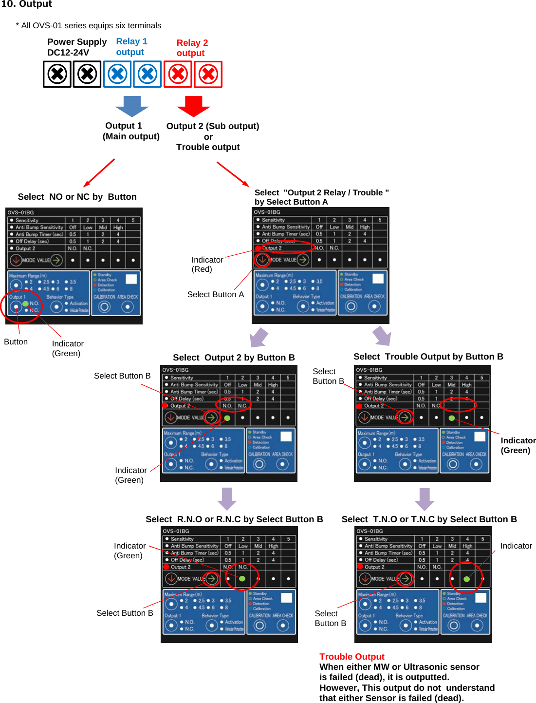
![4)How to check the Detection AreaFor the detection area checking, we recommend to use diameter 60mm pole (Height around 1m~1.5m) as standard.1. Press the Area Check button 7. Check the checking pole to near the Bar [ 5 ]2. Check the Indicator turn to Green flashing 8. Check the Indicator turn to Green LED flashing (Not detect pole)3. Put the Checking Pole to corner of assumed loop coil area [ 1 ]4. Leave from detection area 9. Press the Area Check button or wait for5. Check the indicator turn to Red flashing 30 sec. With Green LED flashing10. Completed.6. Repeat 3-5 for [ 2 ] [ 3 ] and [ 4 ]1. Press the " Area Check " button 7. Check the checking pole to near the Bar [ 2 ]2. Check the indicator turn on to Green LED flashing. 8. Check the Indicator turn to Green LED flashing (Not detect pole) (keep Green flashing)3. Put the checking pole to expected area Top [ 1 ]4. Leave from detection area5. Check the indicator turn to Red flashing 9. Press the Area Check button or wait for 30 sec. With Green LED flashing10. Completed.SS[1][2][3][4]OVS-01BGBehavior Position :Activation OVS-01BGBehavior Position : SafetyBarExample[5]Assumed Loop Coil area(LC1)AssumedLoop Coil area(LC2)Checking PoleArea CheckbuttonExampleS1[2][1]OVS-01BGChecking PoleBarArea Checkbutton](https://usermanual.wiki/Ox-Co/OVS01/User-Guide-2941140-Page-4.png)
![8. Detection Area ・OVS-01BG / BGB This model dose not equip the narrow lens. ・OVS-01CC / CCB / PK / PKB This model equip the narrow lens.9. MW and Ultrasonic ・OVS-01 series equips MW and Ultrasonic sensor. ・Presence detection is possible by FMCW. ・Ultrasonic Sensor detect near side range. ・Detection logic ①MW detect a car first. ②When MW detect a car, Ultrasonic can be possible to detect. ③Output is OR gate of MW and Ultrasonic sensor.-250-200-150-100-500501001502002500 100 200 300 400 500Z [cm]X[cm]Vertical*Car is detected by MW sensor first.*When MW detect a car, Ultra sonic sensorcan be possible to detect Car is detected by Ultrasonic sensorHuman is not detectedUltrasonic sensordetection area-250-200-150-100-500501001502002500 100 200 300 400 500Y[cm]X[cm]HorizontalMW area without Narrow LensMW area with Narrow LensUltrasonic Detection AreaMW sensordetection areaUltrasonic sensordetection areaMW sensordetection areaHuman is not detected](https://usermanual.wiki/Ox-Co/OVS01/User-Guide-2941140-Page-7.png)