Ox Co OVS01 Vehicle detection sensor User Manual Users manual
Optex Co Ltd Vehicle detection sensor Users manual
Ox Co >
Users manual
VEHICLE DETECTION SENSOR
OVS-01 BG / BGB for BARRIER GATE
OVS-01 CC / CCB for CAR COUNTING
OVS-01 PK / PKB for PARKING
This device complies with part 15 of the FCC Rules. Operation is subject to the following two conditions:
(1) This device may not cause harmful interference, and (2) this device must accept any interference received,
including interference that may cause undesired operation.
FCC WARNING(For USA)
Changes or modifications not expressly approved by the party responsible for compliance could void the
user's authority to operate the equipment.
-NOTICE-
This equipment has been tested and found to comply with the limits for a Class B digital device, pursuant to part 15 of
the FCC Rules. These limits are designed to provide reasonable protection against harmful interference in a residential
installation.This equipment generates, uses and can radiate radio frequency energy and, if not installed and used in
accordance with the instructions, may cause harmful interference to radio communications. However, there is no
guarantee that interference will not occur in a particular installation. If this equipment does cause harmful interference
to radio or television reception, which can be determined by turning the equipment off and on, the user is encouraged
to try to correct the interference by one or more of the following measures:
-Reorient or relocate the receiving antenna.
-Increase the separation between the equipment and receiver.
-Connect the equipment into an outlet on a circuit different from that to which the receiver is connected.
-Consult the dealer or an experienced radio/TV technician for help.
-NOTICE-
1.The antennas cannot be exchanged.
2.To comply with FCC RF exposure compliance requirements, aseparation distance of at least 20cm must be
maintained between the antenna of this device and all persons.
V
ehicle Detection Sensor OVS-01 series
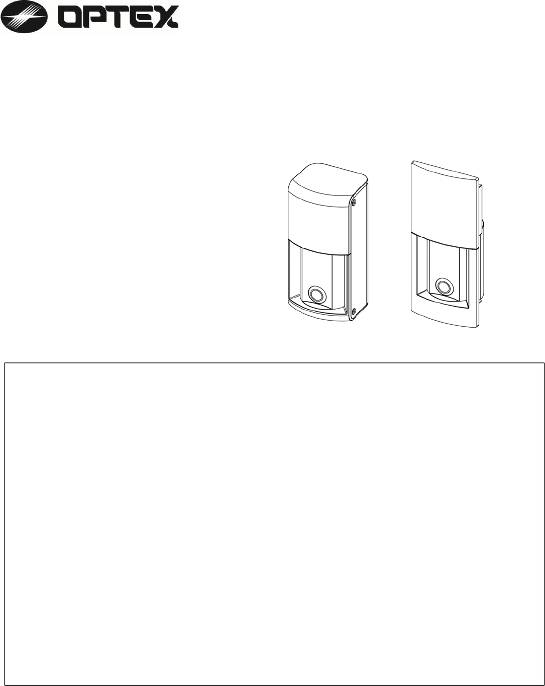
1) Product Line-Up
2
)
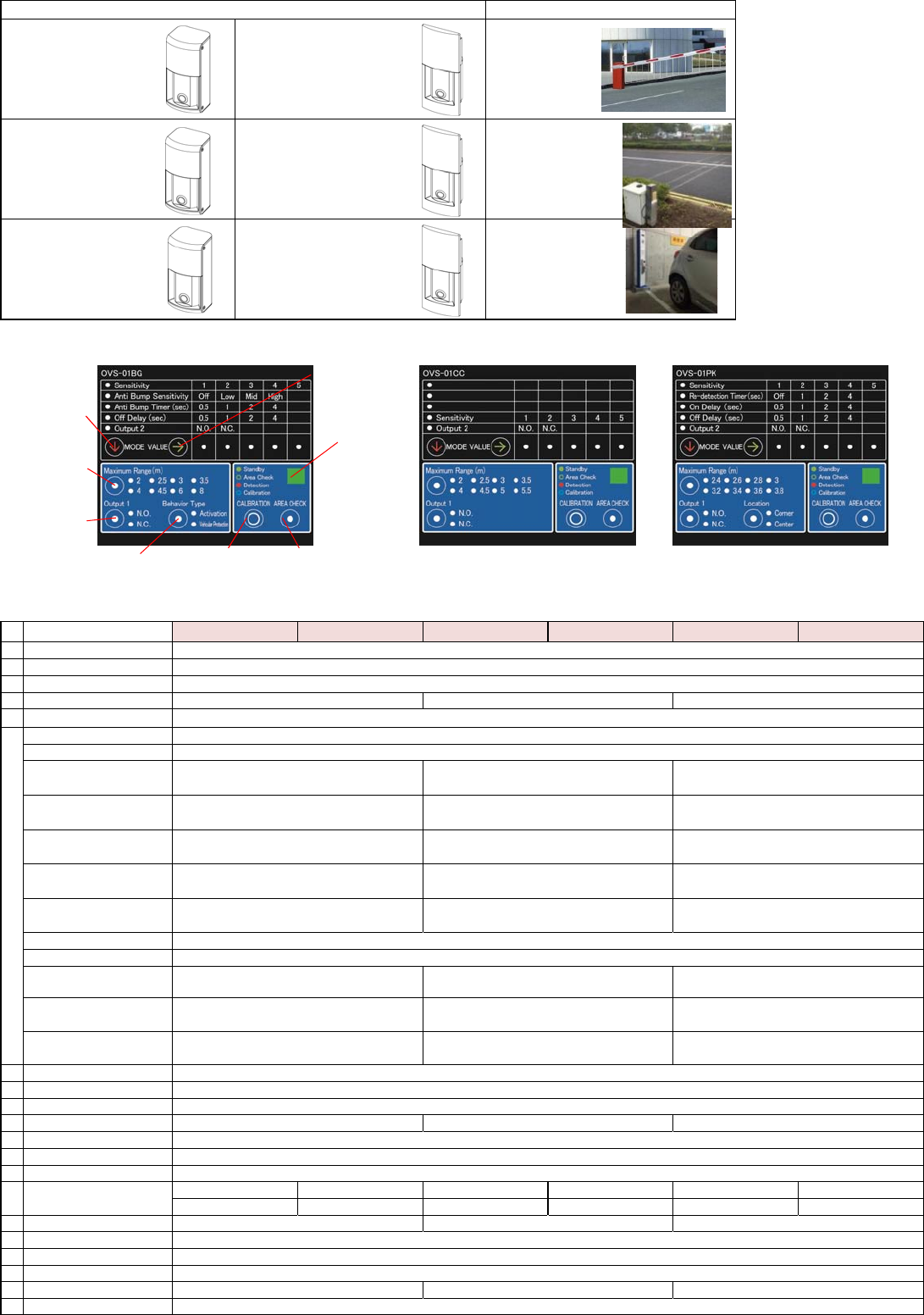
Specifications
1 Power Supply
2 Current Draw
3 Output
4 MW detection Range
5
7Mode
Sensitivity
Anti Bump Sensitivity
Anti Bump Timer
Re-detection Timer
Off Delay
On Delay
Output 1 NO/NC select
Output 2 Relay/Trouble
Maximum Range
(MW)
Behavior Type
Location
8 Human cancel
9 Calibration
10 Area Check
11 Response Time
12 Operating temperature
13 Operating Humidity
14 Protection Category
16
17 Reset
18 Frequency
19 Indicator
20 Narrow Lens
21
-
Radio approved standard
EquippedEquipped
FCC Parts 15 Subpart C:2013, ARIB STD-T73 1.2 and R & TTE
Back to default, Press one sec. " Area Check " and " Calibration " button same time
MW : 24GHz, Ultrasonic : 58KHz
3 (Three) color LED Standby :Green, Area check : Not detect Green flashing, Detect Red, Calibration : Blue flashing
OVS-01PKB
OVS-01BG
OVS-01CC
OVS-01BGB
OVS-01CCB
Barrier Gate
Car Counting
OVS-01PK OVS-01PKB Parking
Ultrasonic Detection Range
0.5,1.0, 2.0, 4.0sec selectable by Select button
Default 2 sec
0.5,1.0, 2.0, 4.0sec selectable by Select button
Default 2 sec
Application
Item OVS-01BG OVS-01BGB OVS-01CC OVS-01PK
Type designation
0.5,1.0, 2.0, 4.0sec selectable by Select button
Default 2 sec
-
0.5,1.0, 2.0, 4.0sec selectable by Select button
Default 2 sec --
300ms
-30 〜50℃
93% max.
Corner / Center
selectable by Select button --
Equipped
By Calibration button
Detection Speed
OVS-01CCB
DC12-24V±10%
Heater ON:150mA max. (Heater Off: 80mA max.)
2(Two) outputs ( Output 1/ Output 2 ) 1a Relay output 30V, 0.3A
0.8 - 8m 0.8 - 3m0.8 - 5.5m
0.1 - 1.5m Fixed
Off, Low, Mid. High selectable by Select button
Default Mid.
-
--
By Area Check button
500ms 500ms
5 level (1,2,3,4,5) selectable by Select button Default 3
NO / NC selectable by select button Default NO
Output 2 NO / Output 2 NC / Trouble output NO / Trouble output NC selectable by Select button Default Output 2 NO
-
selectable by Select button Default 4m
8 level (2, 2.5, 3, 3.5, 4, 4.5, 6, 8m) 8 level (2.4, 2.6, 2.8, 3, 3.2, 3.4, 3.6, 3.8m)
selectable by Select button Default 3.2m
8 level (2, 2.5, 3, 3.5, 4, 4.5, 5, 5.5m)
selectable by Select button Default 4m
-
-
-
-
Activation / Vehicular Protection
selectable by Select button
0.5,1.0, 2.0, 4.0sec selectable by Select button
Default 2 sec
15 Sensor Aiming Adjust Tilt:Not available
Pan : ±15°
Tilt:Not available
20km/h max.60km/h max.
20km/h max.
IP65
Pan : ±30° Pan : ±30° Pan : ±15°
Tilt:Not available Tilt:Not available
Pan : ±30° Pan : ±15°
Tilt:Not available Tilt:Not available
OVS-01BG Operation Panel
Indicator
Area Check
Button
Select
Button
Calibration
Button
Select
Button
Select
Button
Select
Button
Select
Button
OVS-01CC Operation Panel OVS-01 PK Operation Panel
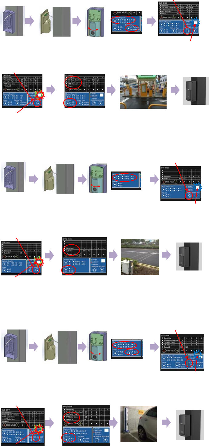
3) Installation
1. Install the Base to
Square Pillar or Wall 2. Wiring 3. Adjust Sensor Angle,
Maximum Range and
Behavior Type
4. Calibration
Press the Calibration button
Indicator
*Blue LED flashing (8 sec.).
*Blue LED fast flashing (2 sec.)
*Blue LED to Green LED
*Completed
5. Area Check
Press the Area Check button 7. System Check 8. Put the Cover
6. Set the Parameter
Anti Bump Sensitivity
Anti Bump Timer
Off Delay
Output 2
Output 1
OVS-01CC / CCB
OVS-01BG / BGB
Indicator
*Green LED flashing
*Red flashing when detecting Human,
Vehicle Test pole
*Press the Area Check button or
Wait for 30 sec. with Green LED flashing
*Completed
1. Install the Base to
Square Pillar or Wall 2. Wiring 3. Adjust Sensor Angle
and Maximum Range 4. Calibration
Press the Calibration button
Indicator
*Blue LED flashing (8 sec.).
*Blue LED fast flashing (2 sec.)
*Blue LED to Green LED
*Completed
5. Area Check
Press the Area Check button
Indicator
*Green LED flashing
*Red flashing when detecting Human,
Vehicle Test pole
*Press the Area Check button or
Wait for 30 sec. with Green LED flashing
*Completed
6. Set the Parameter
Off Delay
Output 2
Output 1
7. System Check 8. Put the Cover
OVS-01PK / PKB
1. Install the Base to
Square Pillar or Wall 2. Wiring 3. Adjust Sensor Angle
and Maximum Range 4. Calibration
Press the Calibration button
Indicator
*Blue LED flashing (8 sec.).
*Blue LED fast flashing (2 sec.)
*Blue LED to Green LED
*Completed
5. Area Check
Press the Area Check button
Indicator
*Green LED flashing
*Red flashing when detecting Human,
Vehicle Test pole
*Press the Area Check button or
Wait for 30 sec. with Green LED flashing
*Completed
6. Set the Parameter
Off Delay
Output 2
Output 1
7. System Check 8. Put the Cover
4
)
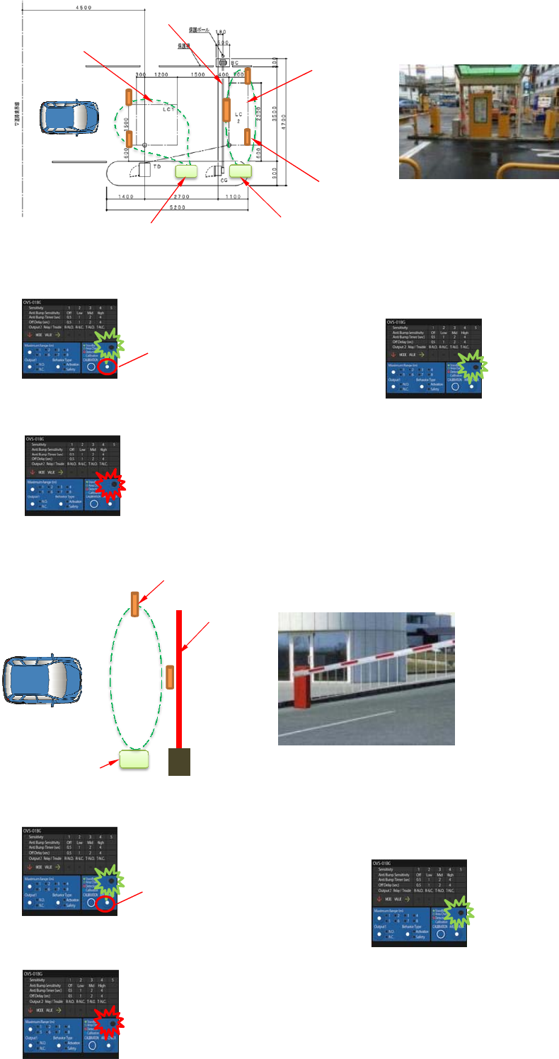
How to check the Detection Area
For the detection area checking, we recommend to use diameter 60mm pole (Height around 1m~1.5m) as standard.
1. Press the Area Check button 7. Check the checking pole to near the Bar [ 5 ]
2. Check the Indicator turn to Green flashing 8. Check the Indicator turn to Green LED flashing
(Not detect pole)
3. Put the Checking Pole to corner of assumed loop coil area [ 1 ]
4. Leave from detection area 9. Press the Area Check button or wait for
5. Check the indicator turn to Red flashing 30 sec. With Green LED flashing
10. Completed.
6. Repeat 3-5 for [ 2 ] [ 3 ] and [ 4 ]
1. Press the " Area Check " button 7. Check the checking pole to near the Bar [ 2 ]
2. Check the indicator turn on to Green LED flashing. 8. Check the Indicator turn to Green LED flashing
(Not detect pole)
(keep Green flashing)
3. Put the checking pole to expected area Top [ 1 ]
4. Leave from detection area
5. Check the indicator turn to Red flashing 9. Press the Area Check button or wait for
30 sec. With Green LED flashing
10. Completed.
SS
[1]
[2]
[3]
[4]
OVS-01BG
Behavior Position :Activation OVS-01BG
Behavior Position : Safety
Bar
Example
[5]
Assumed
Loop Coil area
(LC1)
Assumed
Loop Coil area
(LC2)
Checking Pole
Area Check
button
Example
S1
[2]
[1]
OVS-01BG
Checking Pole
Bar
Area Check
button
5) Other Precaution
1. The detection area of Ultrasonic sensor should not contact with anything,
(the ground, flower pot, the box etc.)
2. Mounting Height 60-80cm will have 100% performance.
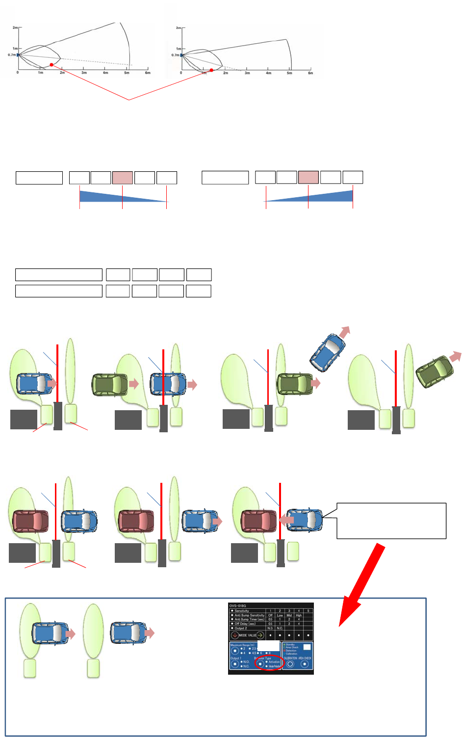
3. Sensitivity Level (Human detection and Vehicle detection)
The following are relation between Human cancel and Vehicle detection.
Position 3 is used generally.
4. Anti-Bump function
Generally, Anti Bump Sensitivity position use " Off " position. Anti Bump Time function does not work in the Off position.
However, If more safety is required to avoid the Bar contact with Vehicle, Anti-Bump function will be used.
* General Application : Anti-Bump Function ( Sensitivity : Off)
* Use Anti Bump Function (Sensitivity Mid )
Ground
1Sensitivity 2 3 4 5
High Low
Human Cancel
1Sensitivity 2 3 4 5
High
Low
V
ehicle Detectio
n
Vehicle Detectio
n
around 97%
S1
S2
OVS-01BG OVS-01BG
Gate Bar
Ticket
Machine
S1
S2
Anti Bump Sensitivity
Anti Bump Time
Off Low HigMid
0.5 1.0 4.02.0
S1
S2
S1
S2
S1
S2
OVS-01BG OVS-01BG
S1
S2
S1
S2
S2
S2
Note
Example
-5°OK. (Detection area is not
contacting with the ground) -15°NG. (Detection area is contacting
with the ground)
Detection area of Ultrasonic Sensor
Ground
Vehicle Detectio
n
around 99.9% Vehicle Detectio
n
around 99.999
%
Not detect
Two-Tree Human 100% not detect
One Human Around 92-95%
not detect one Human
Ticket
Machine
Ticket
Machine Ticket
Machine
Gate Bar is down Gate Bar is Up Gate Bar is going down Gate Bar is Down
Gate Bar is Up Gate Bar is going down Suddenly Vehicle comes back
by slop etc.
In this case, Bar have to be up
immediately to avoid contacting
with Vehicle.
Leave from the detection area
* After Vehicle leave from the detection area,
Sensitivity is more sensitive for 0.5 or 1 or 2 or 4 sec. (selectable by Anti-Bump timer).
(During Anti Bump function is working, Human cancel function dose not work.)
* Sensitive level is selected. (Low, Mid. High ). Generally Mid position is used.
Note : Anti Bump function works in the only Behavior position "Safety"
Ticket
Machine Ticket
Machine
Ticket
Machine
Gate Bar
Gate Bar
Gate Bar Gate Bar
Gate Bar Gate Bar
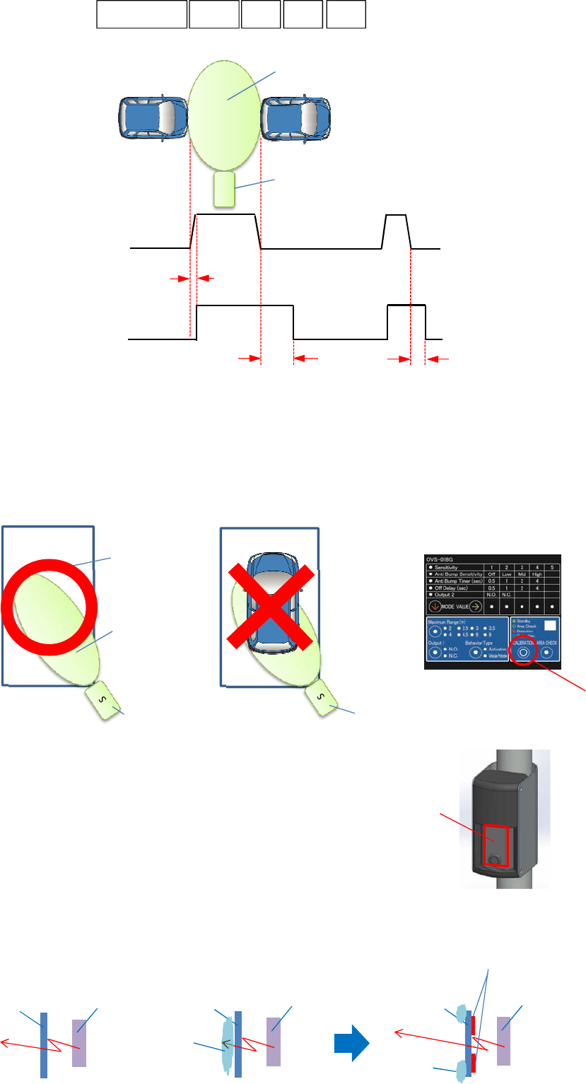
5. Off Delay Timer
6. Calibration
* Calibration must be definitely executed after installation.
* Calibration must be executed with stable parking condition..
It mean there are no Vehicle, human, Big plant pot and Box etc within the detection area
when calibration is executed.
7. Heater
・MW dose not work if snow is stuck to the surface of Ratome..
・Purpose of Heater is to melt the snow that is stuck to the surface of Redame.
・Heater will work when outside temperature become around 0 de
g
ree
automatically.
Radome surface keep around 4 degree or more by this heater.
Snow is not stuck to surface of radome of 4 degree or more
1. Rain becomes snow if tem
p
erature becomes less 0 ℃.
2. 0 ℃ must be
g
uaranteed because it is o
p
eratin
g
tem
p
erature ran
g
e.
3. Heater which is attached to rear surface of radome solves this problem.
4. Heater dose not warm the electrical components inside OVS-01
5. Limit -20 degree is defined by the specification of MW, Ultrasonic
S
On
Off
OVS-01Sensor
OVS -01 Sensor
Relay Output
ON
Off
MW Detection Area
XX
OVS-01
MW Detection
Parking
Good ! Bad !
0.5 sec.
Off Delay time Off Delay time
OVS-01
Sensor Calibration Button
0.5
Off delay 1 2 4
Radome
Selectable Off delay time ( 0.5, 1, 2, 4 second)
MW module
Radome
OK!
MW module
Radome
No!
Snow
MW module
Radome
OK!
Snow
Heater
8. Detection Area
・OVS-01BG / BGB
This model dose not equip the narrow lens.
・OVS-01CC / CCB / PK / PKB
This model equip the narrow lens.
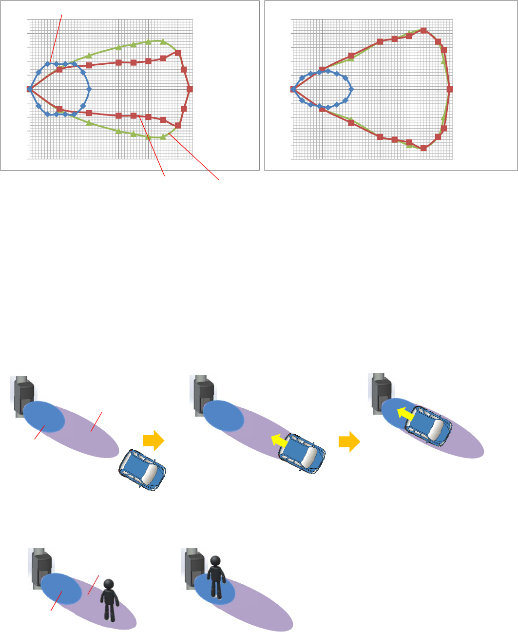
9. MW and Ultrasonic
・OVS-01 series equips MW and Ultrasonic sensor.
・Presence detection is possible by FMCW.
・Ultrasonic Sensor detect near side range.
・Detection logic
①MW detect a car first.
②When MW detect a car, Ultrasonic can be possible to detect.
③Output is OR gate of MW and Ultrasonic sensor.
-250
-200
-150
-100
-50
0
50
100
150
200
250
0 100 200 300 400 500
Z [cm]
X[cm]
Vertical
*Car is detected by MW sensor first.
*When MW detect a car, Ultra sonic
sensor
can be possible to detect
Car is detected by Ultrasonic sensor
Human is not detected
Ultrasonic sensor
detection area
-250
-200
-150
-100
-50
0
50
100
150
200
250
0 100 200 300 400 500
Y[cm]
X[cm]
Horizontal
MW area without Narrow Lens
MW area with Narrow Lens
Ultrasonic Detection Area
MW sensor
detection area
Ultrasonic sensor
detection area
MW sensor
detection area
Human is not detected
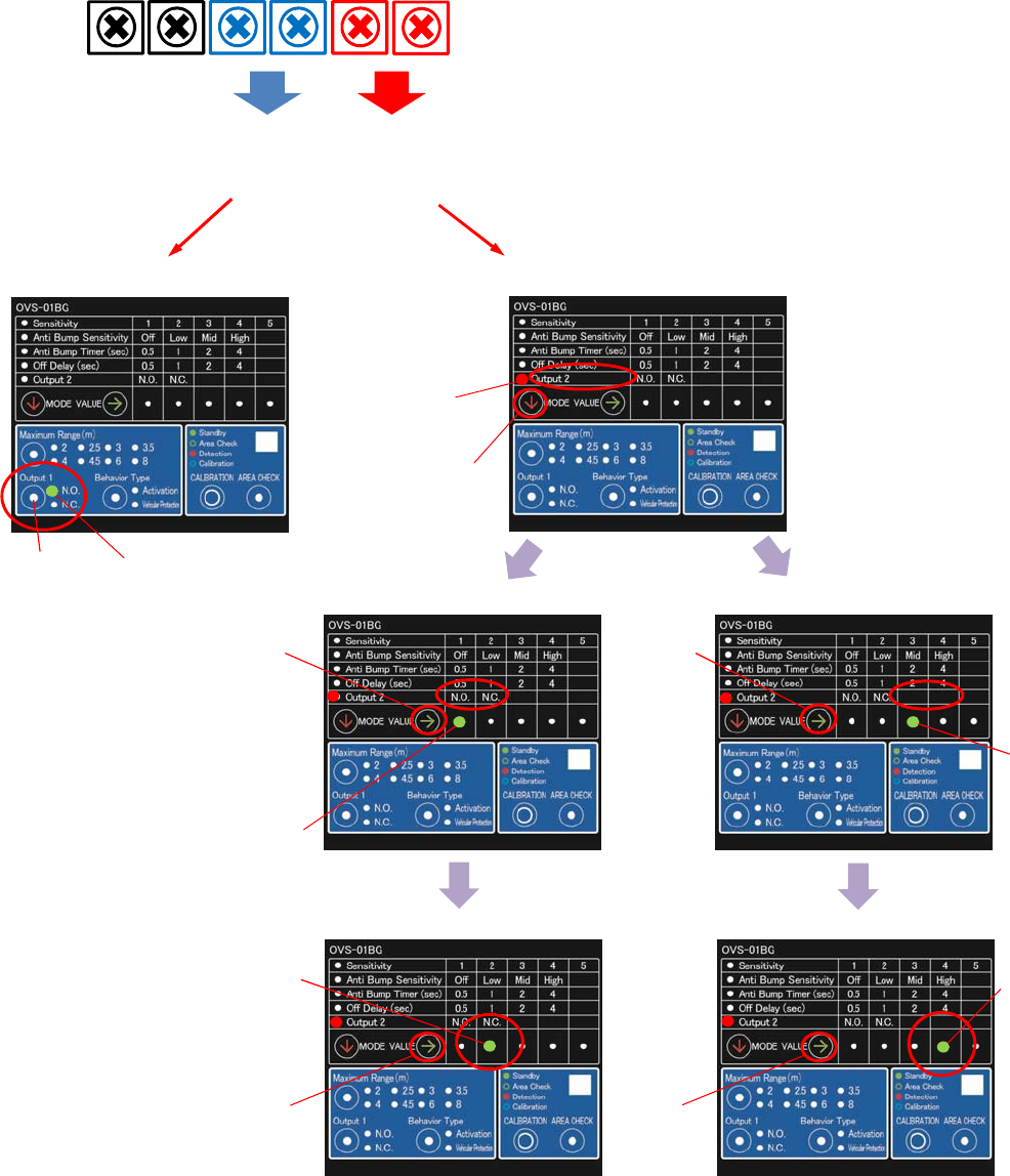
10. Out
p
ut
Power Supply
DC12-24V Relay 1
output Relay 2
output
Output 1
(Main output) Output 2 (Sub output)
or
Trouble output
Select Output 2 by Button B
Select Button A
Select Button B
Select Trouble Output by Button B
Select
Button B
Trouble Output
When either MW or Ultrasonic sensor
is failed (dead), it is outputted.
However, This output do not understand
that either Sensor is failed (dead).
Indicator
(Green)
Indicator
(Red)
Indicator
(Green)
Indicator
(Green)
Indicator
(Green) Indicator
Button
* All OVS-01 series equips six terminals
Select "Output 2 Relay / Trouble "
by Select Button A
Select Button B Select
Button B
Select R.N.O or R.N.C by Select Button B Select T.N.O or T.N.C by Select Button B
Select NO or NC by Button