Oxford Instruments W2CBW003 802.11 b/g + Bluetooth Module User Manual part 2
Oxford Instruments 802.11 b/g + Bluetooth Module part 2
Contents
User Manual part 2

Jeff Jefferson, General Manager
Tubney Woods, TBD
101
X-MET8000 Series User Manual
8
X-MET8000 Series Supervisor’s Guide
Users And Security
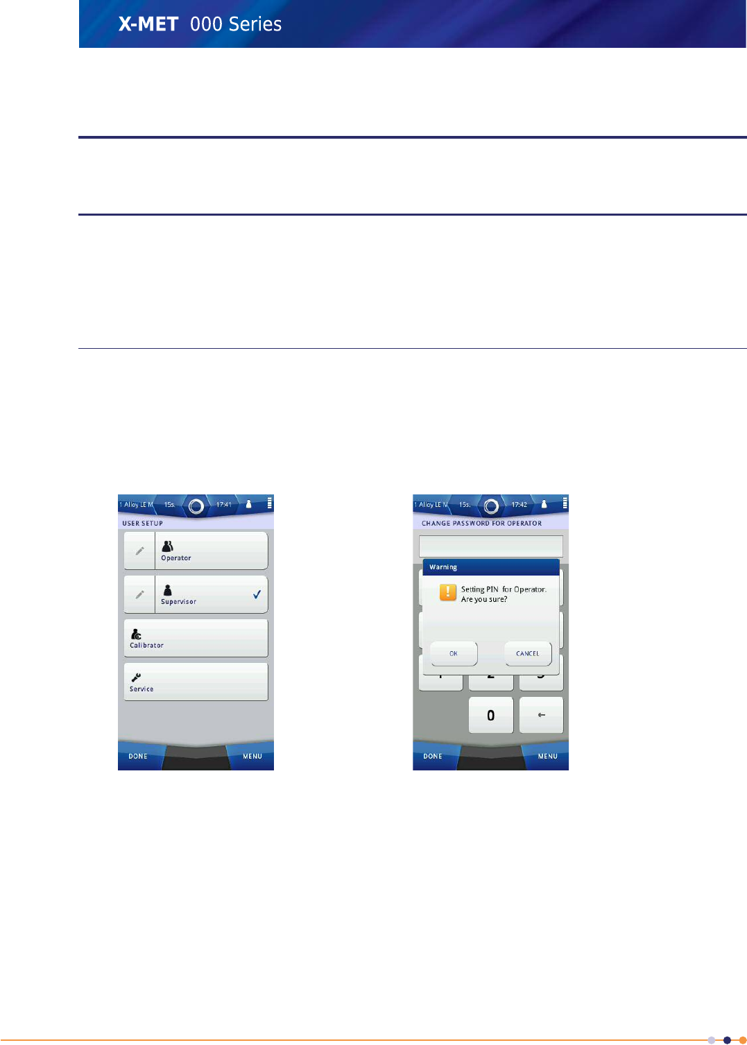
The supervisor can set the Operator password and the Supervisor password. The supervisor should
change both passwords to avoid the factory settings. An operator can change the Operator password.
It is possible to quickly change between users. This allows the supervisor to check which methods and
menu items the operator can access.
Set Passwords
Follow these steps to change the password.
1. Do one of the following:
•Navigate: Menu >Settings >User Setup
•Navigate: Status Bar >User
The User Setup screen appears.
2. Tap Edit (pencil) next to Operator or Supervisor, as applicable.
3. Use the numeric keypad to type the new password, and then tap Done.
A Warning dialog box appears.
4. Do one of the following:
•Tap OK to confirm the new password.
•Tap Cancel to discard the new password.
The User Setup screen appears.
5. Tap Done once or twice to return to the main screen.
102
X-MET8000 Series User Manual
8
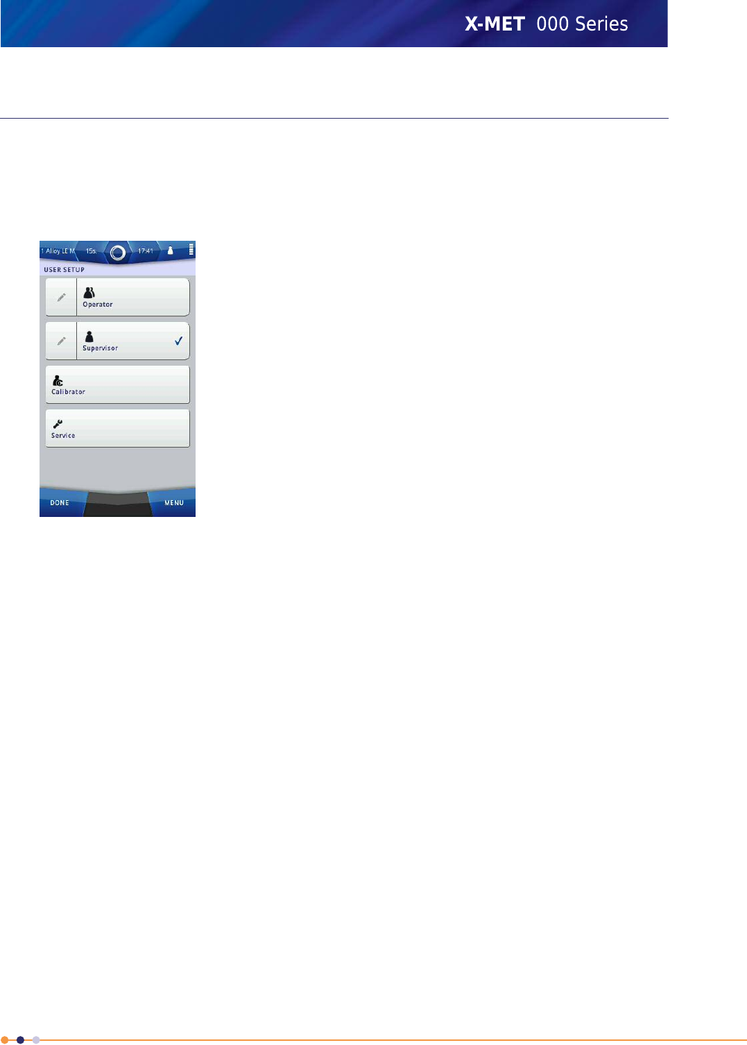
Switch User
Follow these steps to change the password.
1. Do one of the following:
•Navigate: Menu >Settings >User Setup
•Navigate: Status Bar >User
2. Tap the Operator or Supervisor tick box, as applicable.
3. Do one of the following:
•If the switch is to an Operator, tap Done once or twice to return to the main screen.
•If the switch is to a Supervisor, type the password, and then tap Done. Tap Done once or twice
again to return to the main screen.
103
X-MET8000 Series User Manual
8

Advanced Use
The X-MET8000 series is applicable to many different types of measurement. Some applications, for
example Positive Material Identification, require more careful sample preparation and measurement
techniques. The X-MET8000 series assists these applications because it is possible to include additional
information about the sample or the measurement conditions, for example density and thickness, or
GPS information from an external receiver. It is then possible to create a report about the
measurements.
Sample Preparation
Careful sample preparation gives accurate results. Use this information to prepare the different
samples, and follow the guidelines for measurement times.
Prepare Metal Samples
Metals are usually homogeneous, and the results are an accurate representation of the metal. It is
necessary to remove any coating or paint and measure it separately, so that it does not affect the
results.
Measurement times from 2 s give good results, however light elements require between 5 s and 10 s.
Positive Material Identification requires at least a 15 s measurement time, and 30 s is preferable.
Prepare Plastic Samples
The manufacture of plastics uses many metals, for example titanium, lead, cadmium, zinc, iron,
bromine.
Use a sample with a minimum thickness of 3 mm for accurate results. Samples with a minimum
thickness of 1 mm can only give an indication of the composition. It is necessary to remove any coating
or paint and measure it separately, so that it does not affect the results.
X-rays can penetrate a plastic sample and measure whatever is behind it. For example, a measurement
of cable insulation can include the cable. Plastic samples also scatter X-rays. Use a background plate
for accurate measurements and to reduce X-ray scatter.
Measurement times from 30 s give good results.
Prepare Soil Samples
For quick results, it is possible to measure soil samples on the ground. However, more accurate results
require some preparation.
1. Remove any surface debris, for example leaves, grass and stones.
2. Use a 2 mm mesh to remove loose material if there is a lot of debris.
3. Loosen the soil to a depth of a few centimeters and stir to homogenize it.
4. Leave the loosened soil to dry for a few hours or dry it with absorbent paper.
5. Measure the sample on the ground, make sure that the X-MET8000 series is perpendicular to the
surface.
Measurement times from 30 s give good results.
104
X-MET8000 Series User Manual
8

Prepare Powders And Pellets
Powders and pellets are usually not homogeneous, and do not give good results. Make sure that they
are dry, and then grind them. For accurate results, use a grain size less than 80 µm for Cu and Fe,
and less than 20 µm for light elements. However, coarser grain sizes do give good results.
Measurement times from 30 s up to 5 min. can be necessary for good results.
Prepare Printed Circuit Boards And Electronic Components
Printed Circuit Boards are a complex, multi-layer structure with metals, resins, fiberglass and fire
retardant chemicals. The result is an average of all the materials in the measurement area. It can be
difficult to interpret because the X-ray penetration depth depends upon the layers of material. Therefore,
the result is only an indication of the material composition.
It is better to measure individual electronic components in a sample cup. Measurement times from15 s
give good results.
Prepare Solder Samples
To comply with the Restriction of Hazardous Substances directive (RoHS), solders must have a lead
composition less than 1,000 ppm. The most common solder replacement is tin, silver, copper (Sn/Ag/Cu
or SAC). Solder can also contain flux. For accurate results, the solder sample must be homogeneous
and uniform.
If solder is measured on a printed circuit board, the board will also be in the measurement window.
The result will average the composition of the solder and the board. An accurate RoHS analysis of the
solder must measure it on its own, as an homogeneous and uniform sample.
Measurement times from 15 s are required to measure concentrations less than 1,000 ppm.
Prepare Samples For The Bench-top Stand
The bench-top stand is ideal for longer measurement times, which give more accurate results, for
example for Positive Material Identification. Use a sample bag or sample cup, and carefully place it
over the measurement window. Make sure that the lid is firmly closed, and then take the measurement.
Choose The Right Method
The method defines how the X-MET8000 series analyses the sample. The available methods depend
upon the version of the X-MET8000 series.
The X-MET8000 includes ‘LE’ in some of the method names, for example Stainless LE, Alloy LE FP or
Alloy LE Mode. The LE refers to ‘light elements’, and these methods can analyse alloys that include
magnesium, aluminum, silicon, phosphorous and sulfur.
The choice of method optimizes all the measurement parameters within the X-MET8000 series so that
it can make the most accurate measurement for that particular type of sample. It also chooses a
particular calibration to analyze the measurement.
Methods include:
•Auto select modes
•Empirical methods
•Fundamental parameter methods
Auto select modes and fundamental parameter methods are available to an operator. Empirical
methods are not available to an operator, because they can choose an auto select mode instead. All
methods are available to a supervisor.
105
X-MET8000 Series User Manual
8

Auto Select Modes
Auto select modes have a ‘Mode’ suffix’, for example Alloy Mode, RoHS Mode. After an identification
scan, the mode chooses the most applicable method to measure the sample with. It uses this order
to choose a calibration:
1. Empirical methods
2. Fundamental parameter methods
3. A recalculation method
The supervisor can define the recalculation method. It is only used when a sample cannot be identified
by any of the empirical or fundamental parameter calibrations.
Empirical Methods
Empirical methods are available for many alloy groups, for example: aluminum, cobalt, copper, nickel,
low alloy steel, stainless steel, tool steel, solder tin and many more. They compare the unknown
sample to a set of calibration curves and other parameters, and then calculate the concentrations of
the elements. Measurements from a series of standards with known assay values create the calibration
curves for the specific analyzer. The standards have different concentrations of a set of elements that
span a range of concentrations.
Empirical methods are more accurate than fundamental parameter methods, but only when the
unknown sample is within the range of concentrations. If an element in the unknown sample is outside
the range of concentrations, a greater than, >, or less than, <, indicator appears next to the
concentration. If this occurs, review the results and decide if another method is more applicable.
Fundamental Parameter Methods
Fundamental parameter methods are abbreviated to ‘FP’ and uses a complex mathematical analysis
of X-ray fluorescence to calculate the concentrations of elements in the sample. It is less accurate
than a similar empirical method, but it is accurate over a much wider range of element concentrations.
Use Alloy FP to analyze the common elements found in alloys. The
concentration range for each element is from 0 % to 100 %.
Alloy FP
Alloy LE FP is similar to Alloy FP, but also includes the light elements, for
example Mg, Al and Si. The concentration range for each element is from
0 % to 100 %.
Alloy LE FP
Use Metal FP to analyze the elements found in alloys and in particular
hazardous elements, for example Pb, Cd, Hg and Br. The concentration
range for each element is from 0 % to 100 %.
Metal FP
Use Drywall FP to analyze Sr content found in drywall.Drywall FP
Use Drywall LE FP to analyze S and Sr content found in drywall.Drywall LE FP
Use Wood FP to analyze Chromated Copper Arsenate(CCA) treated wood.Wood FP
Use Precious FP to analyze the elements found in alloys and in particular
precious metals, for example Au, Ag, Pt. The concentration range for each
element is from 0 % to 100 %.
Precious FP
Use Aluminum FP to analyze the heavy elements found in aluminum alloys,
for example Cr, Cu, Zn and Pb. But, do not use it to analyze light elements,
for example Al and Si.
Aluminum FP
Use Plastic FP to analyze hazardous elements in plastics, for example Pb,
Cd, Hg and Br.
Plastic FP
106
X-MET8000 Series User Manual
8

Use Soil FP to analyze heavy element concentrations in soil.Soil FP
Soil LE FP is similar to Soil FP, but also includes the light elements, for
example Al and Si.
Soil LE FP
Use Mining FP to analyze the common elements found in mining, for
example Ni, Cu, Zn and Sn.
Mining FP
Mining LE FP is similar to Mining FP, but also includes the light elements,
for example Al, Si, S and P.
Mining LE FP
Mining HighS FP is similar to Mining FPMining MidS FP
Mining HighS FP is similar to Mining FPMining HighS FP
Analyze And Report Results
For RoHS and plastic samples, the density and thickness can affect the result. It is possible to add this
information, and improve the measurement accuracy. However, it is necessary to add both thickness
and density information to improve the results.
Occasionally, a measurement can produce a peculiar result, for example, a much higher concentration
of a particular element. When this occurs, it is possible to view the spectrum for the result. This shows
the raw sample information, with a series of peaks for each of the elements in the sample. It is then
possible to add XRF lines to the spectrum, for each element in the sample. These lines can clearly
show if a peak is associated with a particular element, or not.
An operator can make many measurements during a day. It is possible to record all necessary
information about the sample and the measurement conditions, and include this as Additional
Information. This will assist the measurement analysis when all the measurements are complete. The
supervisor can define the required information. The operator will see the same information fields, and
know that they must add this information. When all the measurements are complete, it is possible to
connect the X-MET8000 series to a PC and create a report. This can include the density and thickness
and any Additional Information. Refer to Operation With A PC on page 40 to create a report.
107
X-MET8000 Series User Manual
8
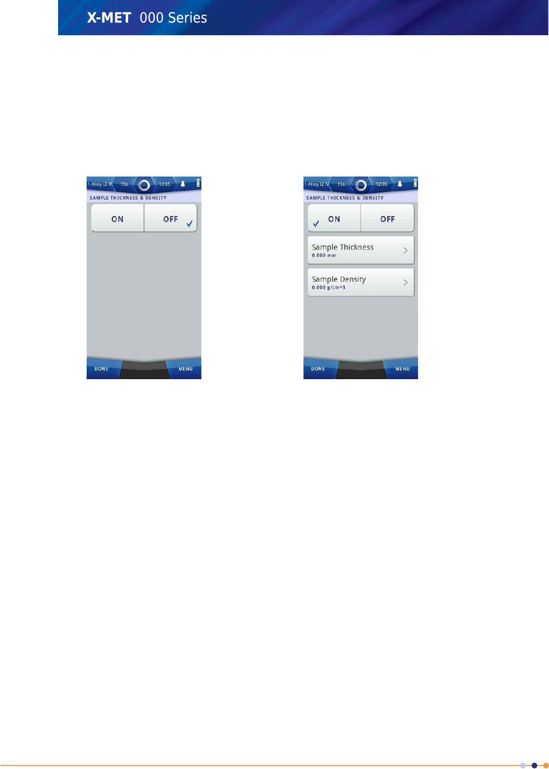
Add Density And Thickness
The density and thickness of the sample are important factors that affect the quality of a measurement.
It is possible to record these values with the sample results. Follow these steps to add density and
thickness information. It is necessary to add both to improve the measurement accuracy.
1. Navigate: Menu >Sample Name >Set Thickness &Density .
The Sample Thickness & Density screen appears.
2. Tap the ON tick box.
The Sample Thickness & Density screen changes.
3. Do one of the following:
•Tap Sample Thickness
•Tap Sample Density
4. Use the numeric keypad to type the value, and then tap Done to return to the Sample Thickness
& Density screen.
5. Tap Done twice again to return to the main screen.
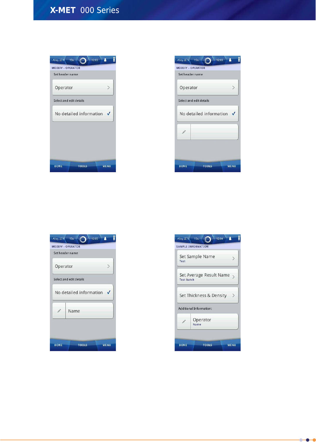
Add An Item To Additional Information
It is possible to add Additional Information about the sample. The measurement result can include
this information. The supervisor can add items for an operator to use and add details to, when they
make measurements. The detail for the item could be a prompt to assist the operator.
These are some examples of Additional Information:
•The name of the operator.
•The sample condition: wet or dry, fine or coarse.
•Notes about the sample preparation: paint or coating removal; use of a sample cup or the
background plate.
Follow these steps to add an item to Additional Information, and then add a detail to the new item.
108
X-MET8000 Series User Manual
8
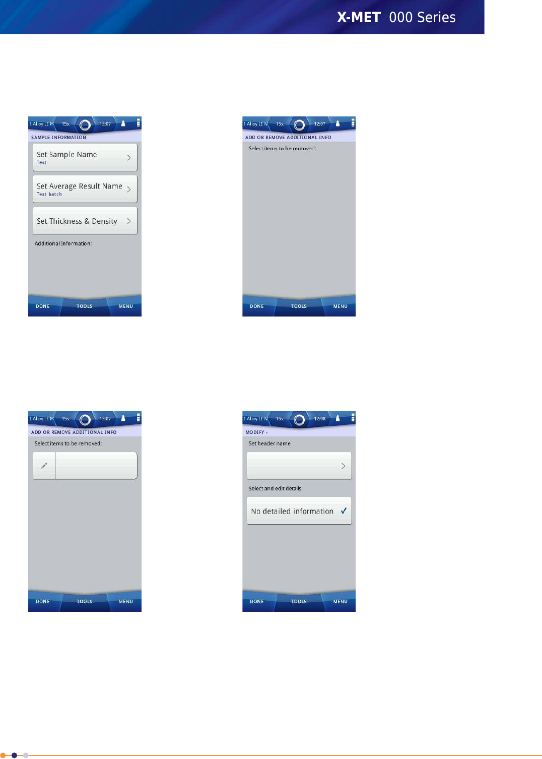
Add a new item.
1. Navigate: Menu >Sample Name .
The Sample Information screen appears.
2. Tap: Tools >Add or Remove .
The Add Or Remove Additional Info screen appears.
3. Tap: Tools >Add New Item .
The Add Or Remove Additional Info screen has a new, blank item.
4. Tap Edit (pencil) next to the new item.
The Modify - screen appears.
5. Tap the blank item box.
109
X-MET8000 Series User Manual
8
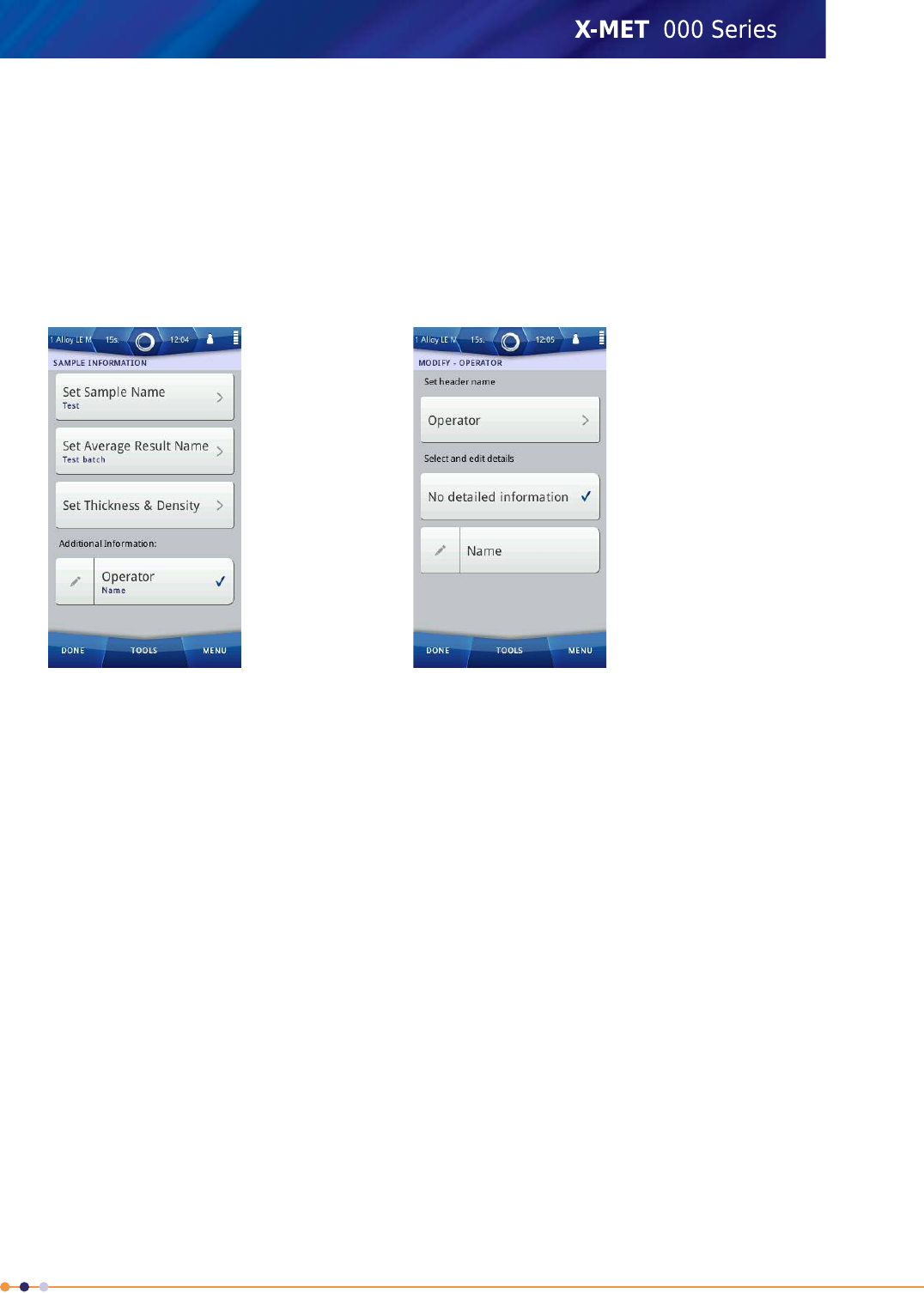
6. Use the virtual keyboard to type the name for the new item, and then tap Done to return to the
Modify - screen.
Add a detail to the new item.
7. Tap: Tools >Add New Detail .
A new, blank detail appears on the Modify - screen.
8. Tap Edit next to the new detail.
9. Use the virtual keyboard to type the new detail, and then tap Done to return to the Modify - screen.
10. Tap the new detail box to select it, and then tap Done to return to the Add Or Remove Additional
Info screen.
11. Tap Done again to return to the Sample Information screen.
The Sample Information screen includes the new item, with its detail.
12. Tap the new item box to select it, and then tap Done to return to the main screen.
110
X-MET8000 Series User Manual
8
Edit Detail For An Item Of Additional Information
It is possible to add Additional Information about the sample. The supervisor can add items for an
operator to use when they make measurements. The operator must edit the details, and make sure
that both the item and the detail for the item are selected.
Follow these steps to edit the details for an item of Additional Information that already exists.
1. Navigate: Menu >Sample Name .
The Sample Information screen appears, with one or more items of Additional Information.
2. Tap Edit (pencil) next to the item of Additional Information.
The Modify - screen appears.
3. Tap Edit next to the detail.
4. Use the virtual keyboard to type the new value for the detail, and then tap Done to return to the
Modify - screen.
5. Make sure that the details box is selected, and if necessary, tap it to select it. Then tap Done.
The Sample Information screen shows the changes to the item of Additional Information.
6. Make sure that the item of Additional Information is selected, and if necessary, tap it to select it.
Then tap Done to return to the main screen.
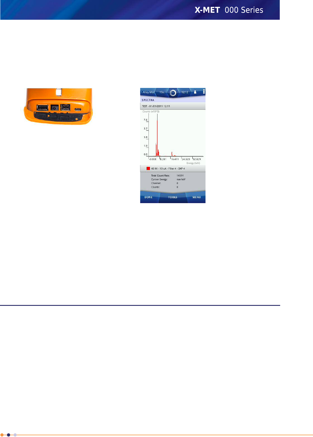
View The Spectra
It is possible to view the X-ray spectrum for a result. This can confirm if an element does have the
concentration shown in the results. It is possible to zoom into the spectrum, and also show the X-ray
fluorescence lines for selected elements.
It is possible for a single result to have more than one spectrum. This is often the case for the
X-MET7500 when it measures light elements. Different measurement conditions produce the spectra,
for example, different excitation voltages. The individual spectra are shown on the same graph in
different colours. It is possible to scroll between the measurement conditions for the spectra.
It is possible to view the spectrum for all results, from the Results screen and the History Results
screen.
111
X-MET8000 Series User Manual
8
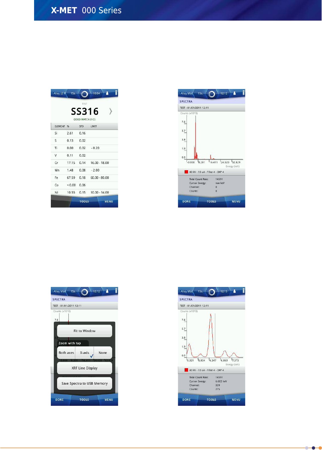
Follow these steps to view the spectrum, when a result is visible.
Access spectrum
1. From the Results screen, the History Results screen or the Test Measurement screen, tap: Tools
>Show Spectra .
The Spectrum screen appears.
2. If there is more than one spectrum, tap the small black arrow at the bottom of the screen on the
left or right.
The Spectrum screen changes to show the other measurement conditions, and its spectrum is put
in front.
Zoom Into The Spectrum
3. Tap Tools.
The Spectrum screen Tools menu appears.
112
X-MET8000 Series User Manual
8
4. Tap one of the Zoom with tap options.
•Choose Both axes to be able to zoom into a small peak.
•Choose X-axis to show each peak relative to the main peak.
5. Tap one of the peaks to zoom into it. Tap it successively to zoom into it again.
A cursor line appears on the spectrum, and moves to where the tap occurred.
The energy at the cursor appears underneath the spectrum.
Press and slide the spectrum to left or right to find the peaks.
6. Tap: Tools >Fit to Window to return to the whole spectrum.
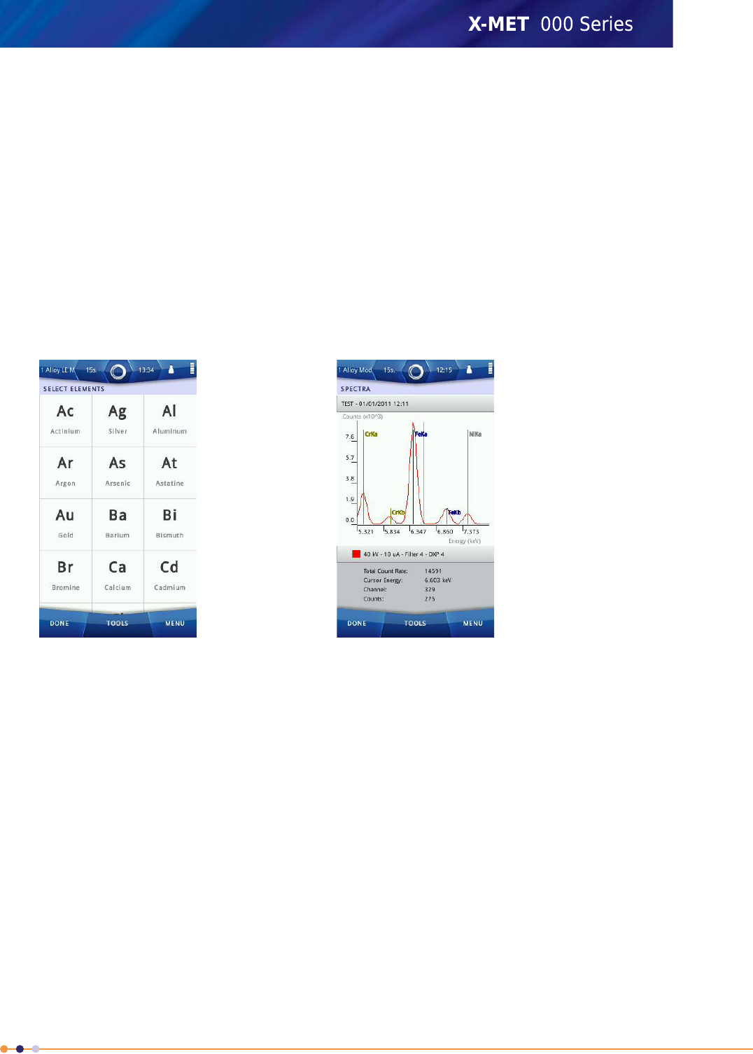
Add XRF Lines To The Spectrum
7. Tap: Tools >XRF Line Display .
The Select Elements screen appears.
8. Tap an element symbol to select it.
Press and slide, or flick the list to scroll up and down to find an element.
Refer to: Select Elements on page 114 to sort and search the element list.
9. Tap Done to return to the Spectrum screen.
The spectrum now includes the XRF lines for the selected elements.
10. Tap Done to return to the Results screen.
113
X-MET8000 Series User Manual
8
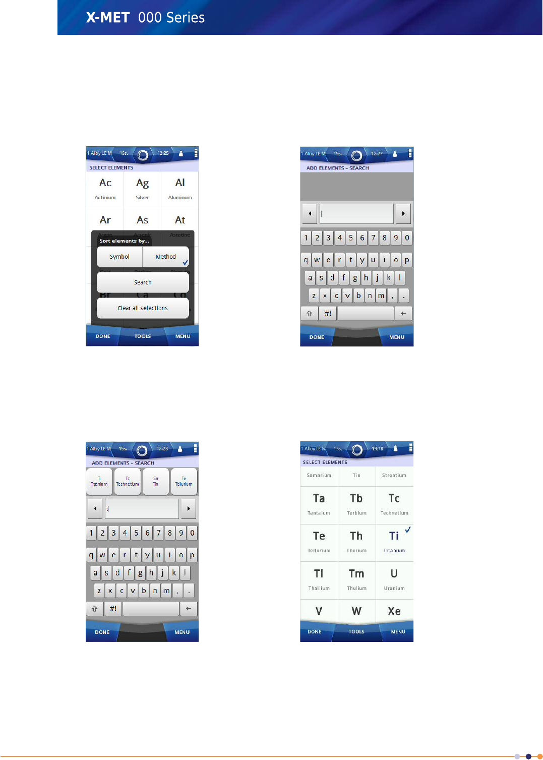
Select Elements
Follow these steps to select elements, when the Select Elements screen appears.
1. Tap Tools to sort and search the element list.
The Select Elements screen Tools menu appears.
2. Tap Search
The Add Elements - Search screen appears, with the virtual keyboard.
3. Type the first letter of the element.
Elements with that first letter in the name or symbol appear.
4. If necessary, type a second letter, or tap the required element if it is visible.
The Select Elements screen appears, with the element selected.
Repeat these steps to add all elements.
114
X-MET8000 Series User Manual
8
5. If necessary, tap Clear all the selections to clear the element selection.
Save The Spectra
Follow these steps to save the spectra to TXT files on a USB memory device.
1. Open the connector cover underneath the display to access the external connections.
2. Plug a USB memory device into the USB A connector.
3. From the Results screen, the History Results screen or the Test Measurement screen, tap: Tools
>Show Spectra .
The Spectrum screen appears.
4. Tap: Tools >Save Spectra to USB Memory .
The spectra are each saved to its own TXT file on the USB memory device.
5. Tap Done to return to the Results screen.
Modify The Results Screen
The X-MET8000 series has powerful features to show results. As well as Normal for single measurements
and Average for batch measurements, a supervisor can create a custom Results screen format. These
can include:
•A specific set of elements.
•The information shown for each element.
•High and low limits for each element, with optional colour coding and an alarm message.
•Alarm messages for combinations of element limits.
Results screen formats do not change the XRF analysis. It is possible to switch from a custom format
with a restricted set of elements to Normal to see the full set of results. Custom formats are ideal for
repetitive analysis and production environments. These can allow an operator to quickly determine
whether a measurement meets specification (pass or fail), or whether a confirmation measurement
is necessary.
115
X-MET8000 Series User Manual
8

When analysing metals, the results are compared to the comprehensive grade table, and all Results
screen formats include grade information. The grade table uses AISI, other available grade tables
include DIN, JIS and Au Karat grades. The supervisor can edit grades, and can add new grades. For
example, a supervisor can use a custom grade to indicate a successful match to a specific set of
criteria. In production environments, a successful match could indicate a pass, and in a RoHS
environment it could indicate a safe sample.
The grade table is selected in the result view settings and should be selected according to the method.
A supervisor would need to instruct an operator to use a specific method or choice of methods, with
a specific Results screen format. This combination of method and Results screen format would allow
an operator to quickly assess samples, and derive the necessary results.
About Results Screen Formats
A supervisor can create a custom Results screen format. This is limited to a specific set of elements,
and only those elements appear on the Results screen. The supervisor can choose the elements to
include in the screen format. This does not, however, affect the actual measurement, but only how
the results from the measurement are shown. If a chosen element is not included in a particular
method, the result for that element is not applicable, and the screen shows ‘N/A’.
The supervisor can choose what information about the elements to include on the Results screen,
such as the concentration unit and displayed columns. The units to show element concentrations and
a choice of Results screen columns.
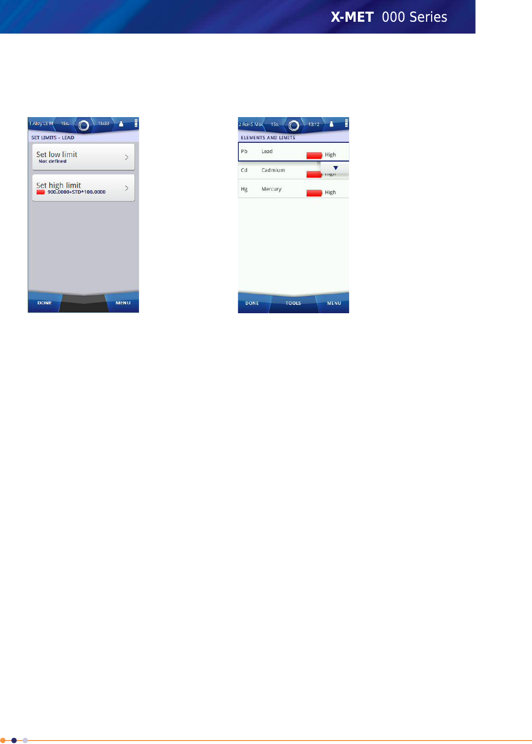
Each element selected for the screen format can have an optional low limit or a high limit or both. If
the result is less than the low limit, or greater than the high limit, then it trips that limit. When a
measurement trips a limit, the screen shows this with a choice of colour or an alarm message or both.
The available colours are from the simple traffic light system: green, orange and red. The supervisor
can define the text of the alarm message. Limits are always a percentage value, even when the Results
screen shows the value in parts per million.
One of the parameters to set is a +/- Coefficient, for the standard deviation. It adjusts the limits to
account for the spread of measurements. The +/- Coefficient is typically an integer between 0 and 5,
and has the effect of reducing the low alarm limit, and increasing the high alarm limit.
In addition to the alarm for each individual element, the supervisor can set one or more additional
alarms that use combinations of the element limits. A combination alarm can use one or more of the
limits set for individual elements. The combination can be a logical OR, or a logical AND. A measurement
trips a logical OR alarm when it trips any of the selected limits, but only trips a logical AND alarm when
it trips all of the selected limits. The supervisor can define the text of the alarm message.
Alarms are only activated after the Minimum Test Time. This is to ensure that the alarms are not
tripped too soon during a measurement.
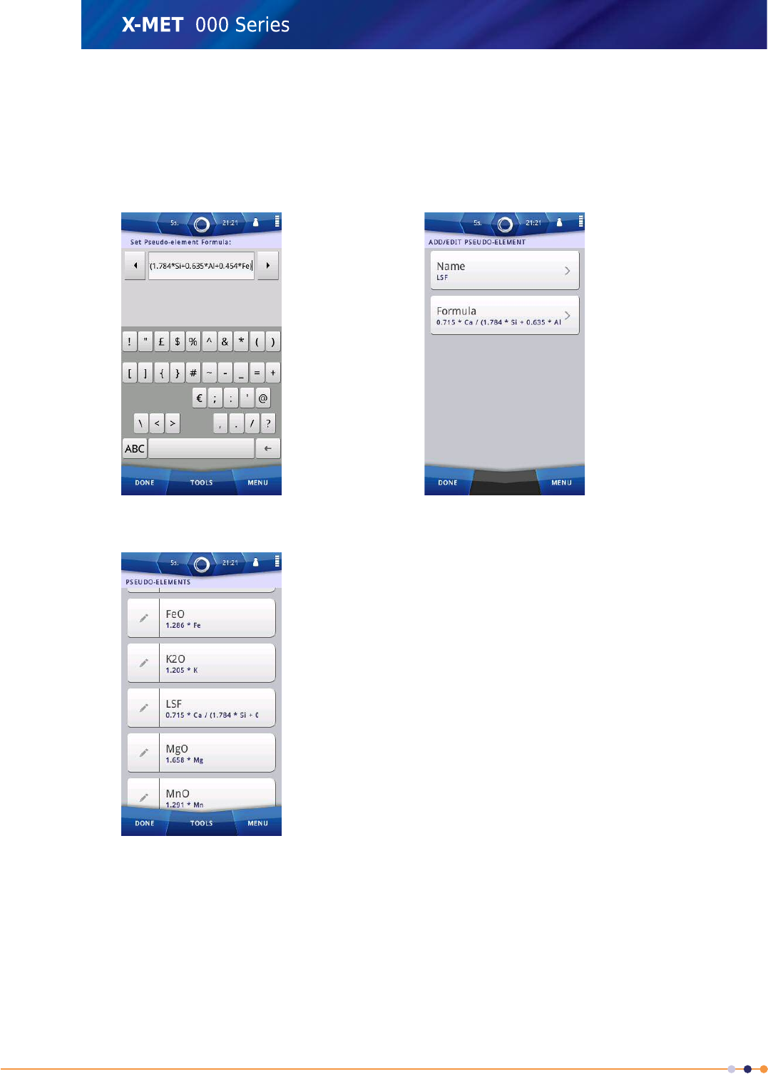
Pseudo-elements
Using Pseudo Elements the X-MET8000 series can show user-specified materials "Pseudo-elements".
Each new Pseudo-element will be stored and added to the list of Pseudo-elements available.
It is possible for a supervisor to add, edit and remove compounds in the Pseudo-elements settings.
A Pseudo-element can use equations to link any elements and analytes together. For example, in the
cement industry they might use the Lime Saturation Factor to control their process "LSF =
0.715*Ca/(1.784*Si+0.635*Al+0.454*Fe)".
116
X-MET8000 Series User Manual
8
Balance
Balance function in the X-MET8000 series informs the user of how much in the sample is not reported.
Balance can be enabled in the Result Format Menu.
Balance = 100% - Sum (all displayed elements).
Balance informs the user of how much in the sample is not “reported”. This could be non-measurable
elements (C, O, N, or lights elements) or elements that the user chose not to display.
Note: “All displayed elements” are all elements selected for display. This does not use the compounds
concentrations. It uses elemental concentrations.
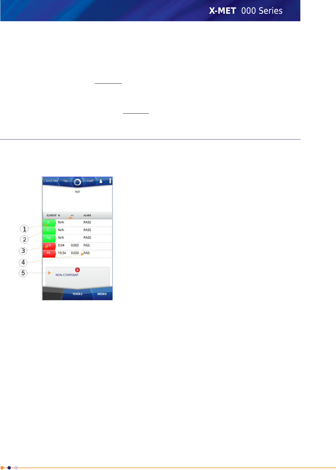
A Custom Results Screen
The X-MET8000 series provides full control of all these aspects of the Results screen.
Table 2: Typical custom Results screen
1. Element list
2. +/- Coefficient
3. Coloured individual alarms
4. Individual alarm message
5. Combination alarm message
Select the elements that appear on the Results screen.Element list
Select the +/- Coefficient that appear on the Results screen.+/- Coefficient
Colour coded alarms can follow the traffic light system.Coloured individual alarms
Create messages for individual alarms.Individual alarm message
Create messages for a combination of alarms.Combination alarm message
117
X-MET8000 Series User Manual
8
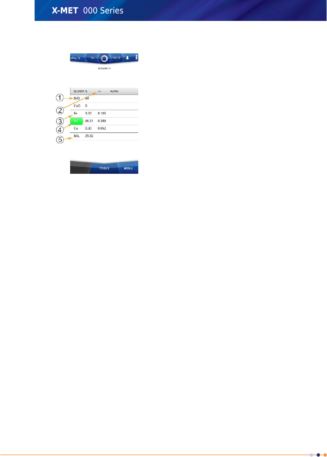
Table 3: Typical custom Results screen with Pseudo-elements and Balance
1. Pseudo-element list
2. +/- Coefficient
3. Element list
4. Coloured individual alarms
5. Balance
The selected Pseudo-elements appear first on the Results screen.Pseudo-element list
Select the elements that appear on the Results screen.Element list
Select the +/- Coefficient that appear on the Results screen.+/- Coefficient
Colour coded alarms can follow the traffic light system.Coloured individual alarms
Balance = 100% - Sum (all displayed elements).Balance
118
X-MET8000 Series User Manual
8
Add A New Results Screen Format
Follow these steps to add a custom results format and select the elements and Pseudo-elements to
include in the results format.
Add A Results Format
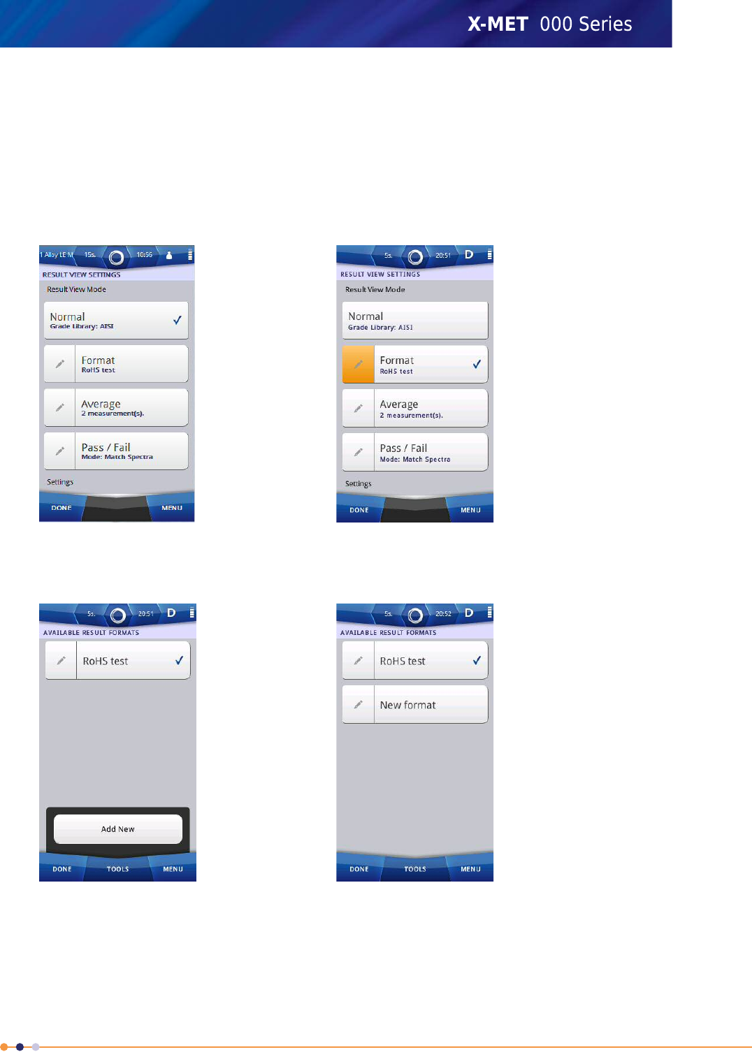
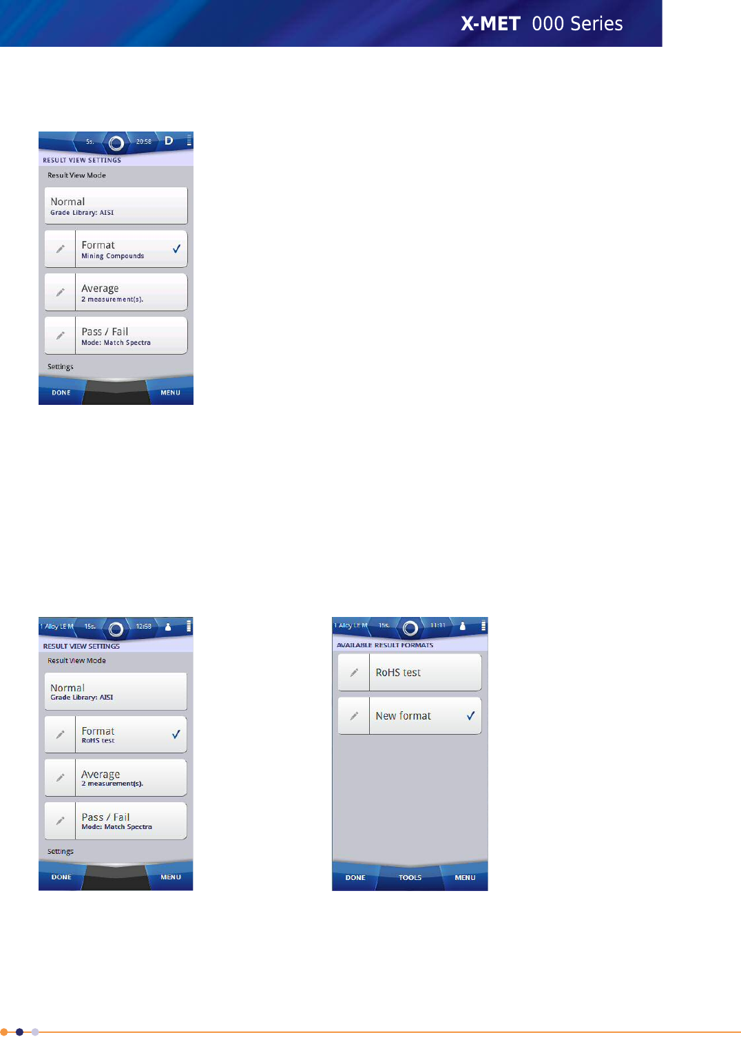
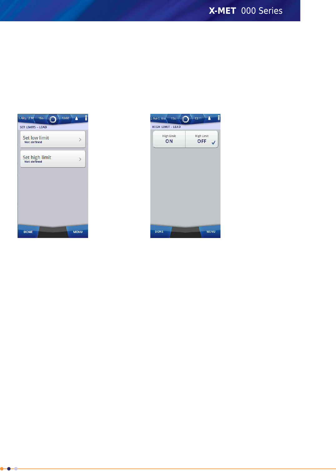
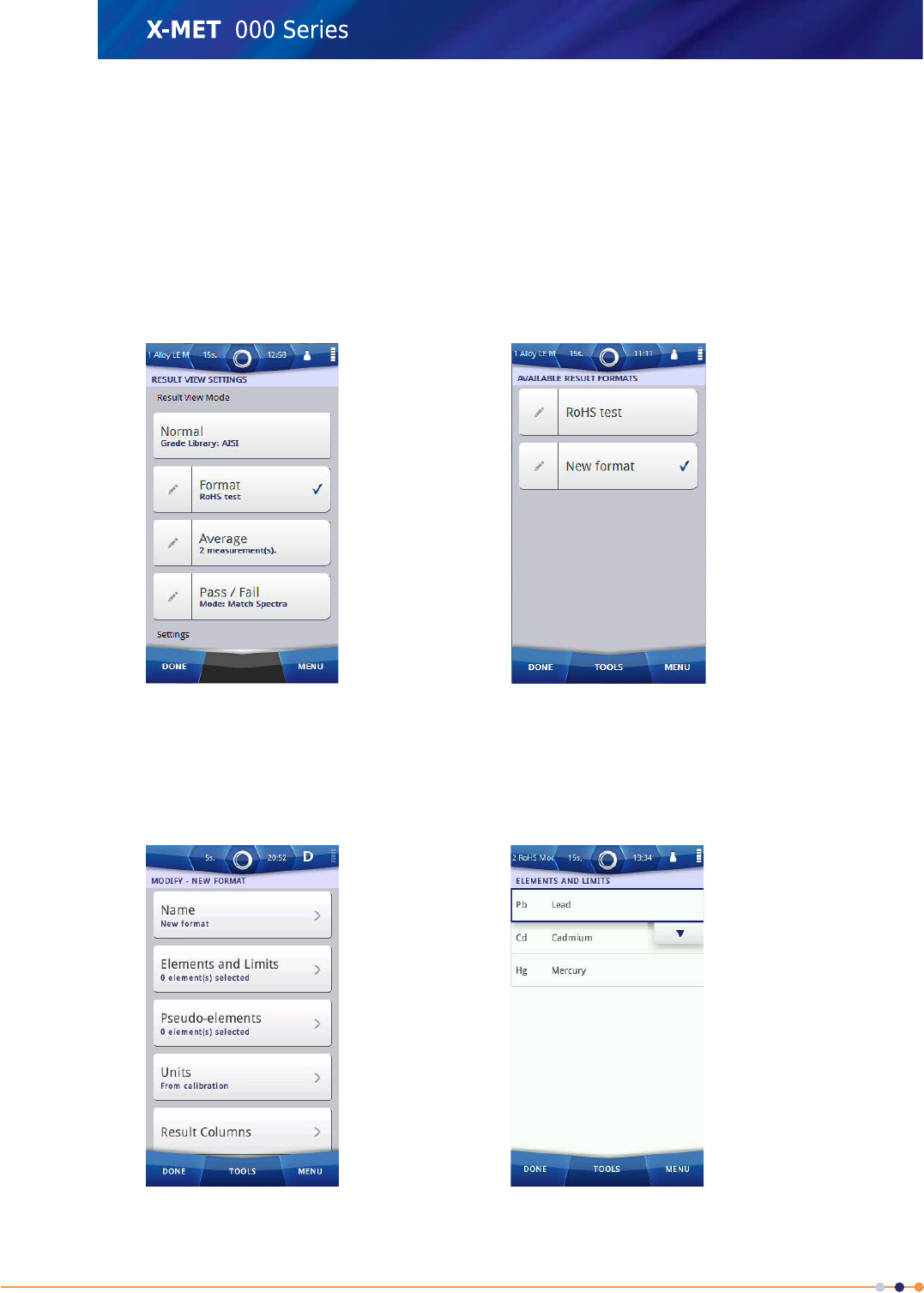
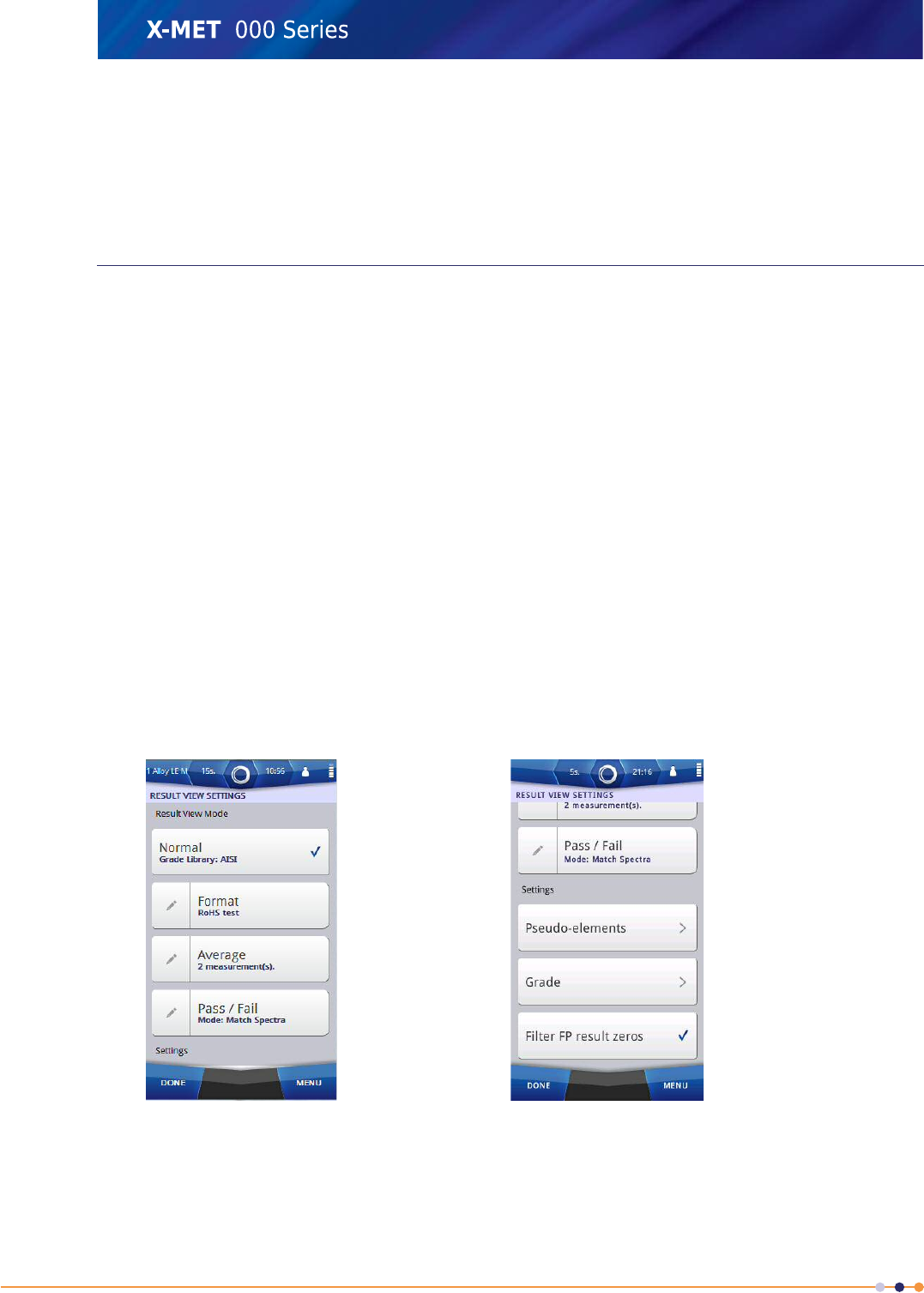
1. Navigate: Menu >Settings >Result View Settings .
The Result View Settings screen appears.
2. Tap Edit (pencil) next to Format to view the available results formats.
The Available Result Format screen appears.
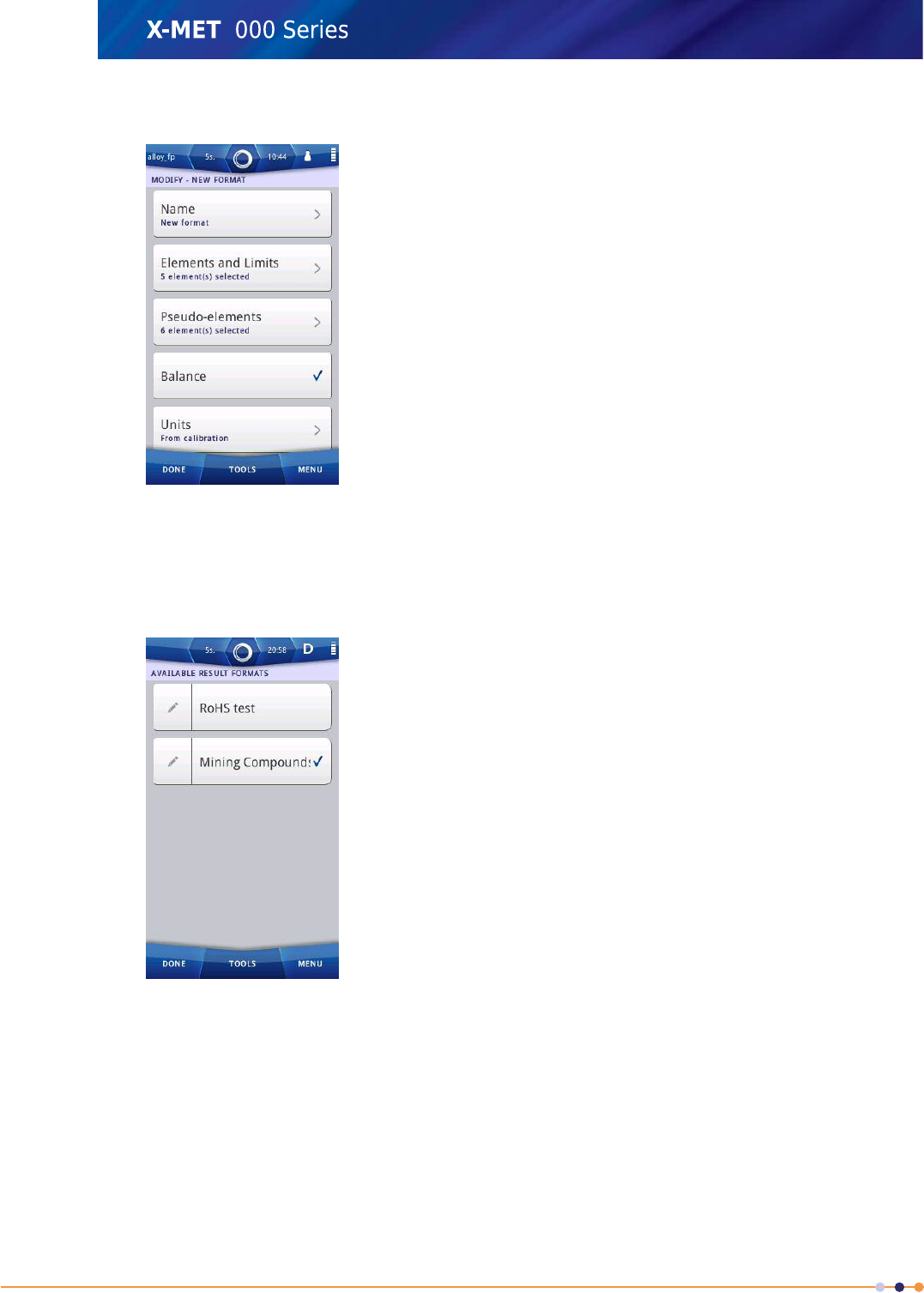
3. Tap: Tools >Add New.
The Available Result Formats screen has a new results format.
119
X-MET8000 Series User Manual
8
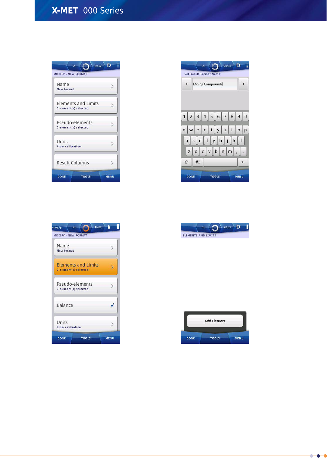
4. Tap Edit (pencil) next to New format.
The Modify - screen appears.
5. Tap: Name to enter a name for the result format.
6. Enter an appropriate name using the virtual keyboard and then tap Done to return to the Modify
- screen.
7. Tap: Elements And Limits.
The Elements And Limits screen appears.
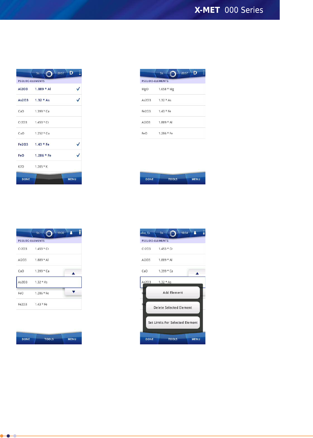
8. Tap: Tools >Add Element.
The Elements selection screen appears.
120
X-MET8000 Series User Manual
8
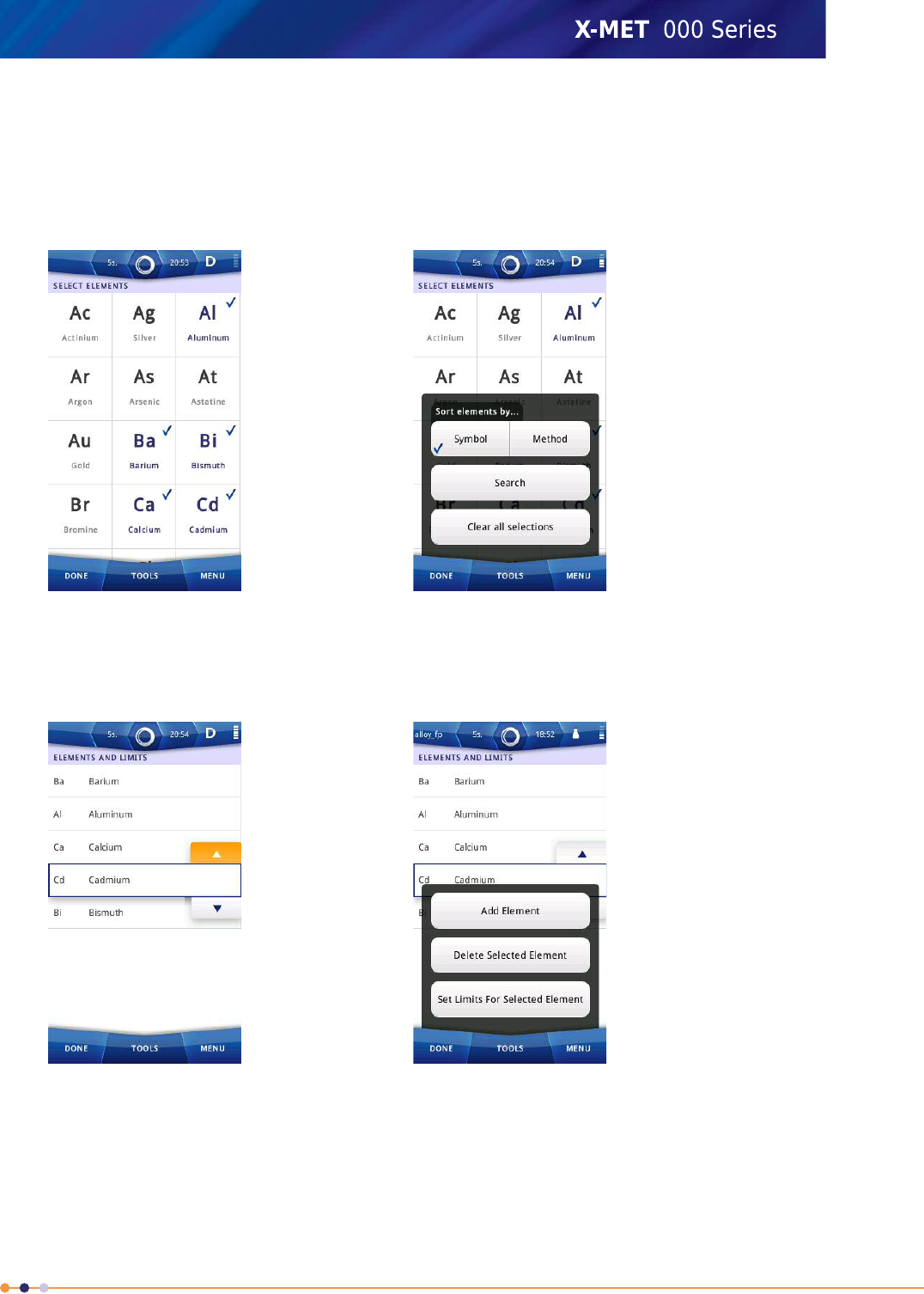
9. Tap an element symbol to select it. Selected elements will have a checkmark.
Press and slide, or flick the list to scroll up and down to find an element.
Refer to: Select Elements on page 114 to sort and search the element list.
Note: It is possible at this stage to select elements even if they are not included in the
methods/calibrations.
10. Tap Done to return to the Elements And Limits screen.
The results format includes the selected elements.
To reorder the element list, tap the up or down arrow on the element line.
11. Tap Tools to add or delete elements from the list, and to set limits for the selected element. To
Add Combination Alarms, refer to Add Combination Alarms on page 132.
12. Tap Done to return to the Modify - screen.
121
X-MET8000 Series User Manual
8
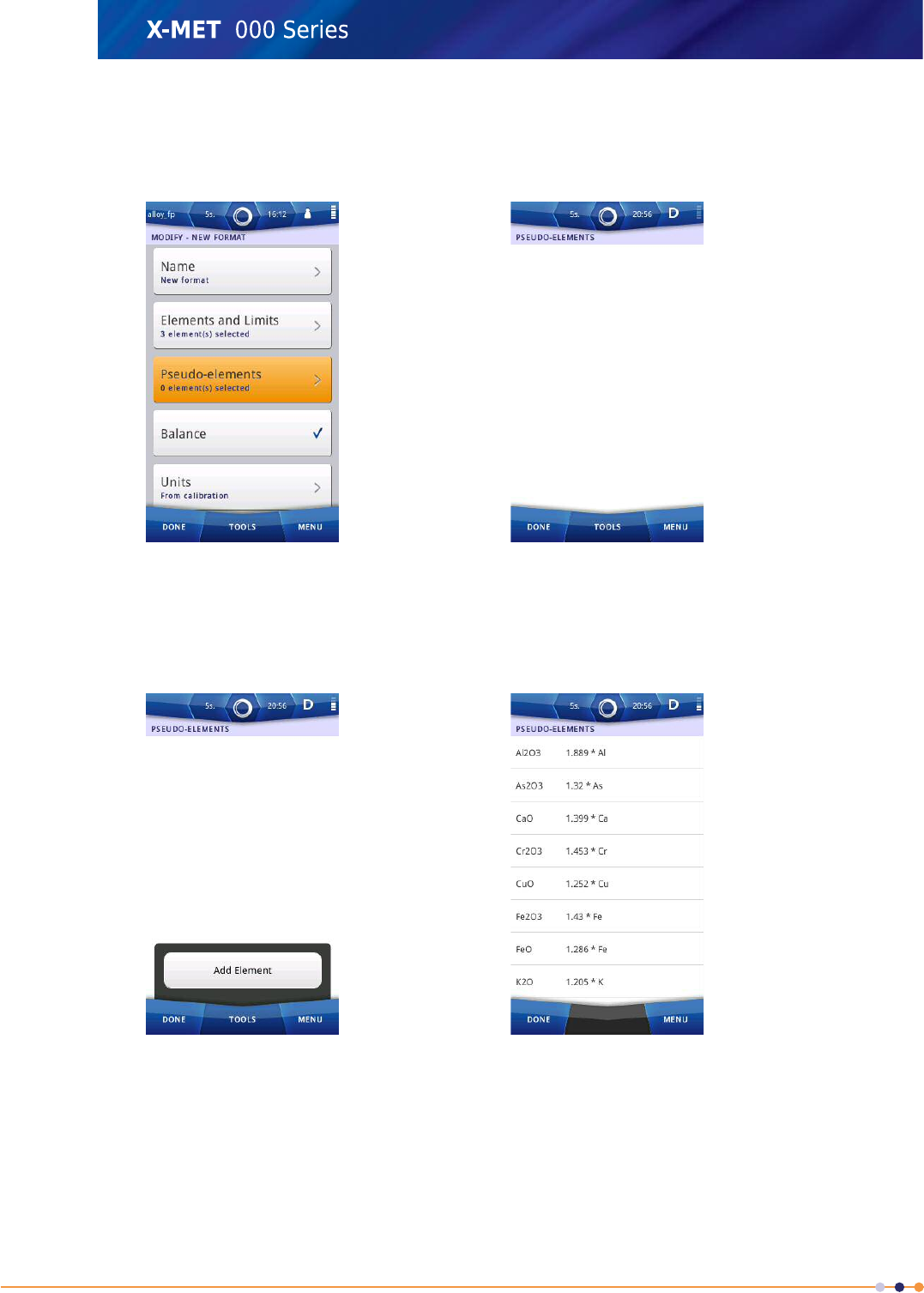
13. Do one of the following:
•Tap Pseudo-elements to add Pseudo-elements to the results format.
•To continue without adding Pseudo-elements, proceed to step 20 on page 124.
14. Tap Tools >Add Element .
The Pseudo-elements list appears.
If the desired Pseudo-element is not listed, the supervisor can create a new one in Results View
Settings.
122
X-MET8000 Series User Manual
8
15. Tick the Pseudo-elements and compounds to include in the result format.
Press and slide, or flick the list to scroll up and down to find an element.
The selected Pseudo-elements have a checkmark next to them.
16. Tap Done to return to the Pseudo-elements screen.
The results format includes the selected Pseudo-elements.
To reorder the Pseudo-element list, tap the up or down arrow on the Pseudo-element line.
17. Tap Tools to add or delete Pseudo-elements from the selection, or to set limits for selected
Pseudo-elements. To Add Combination Alarms, refer to Add Combination Alarms on page 132.
123
X-MET8000 Series User Manual
8
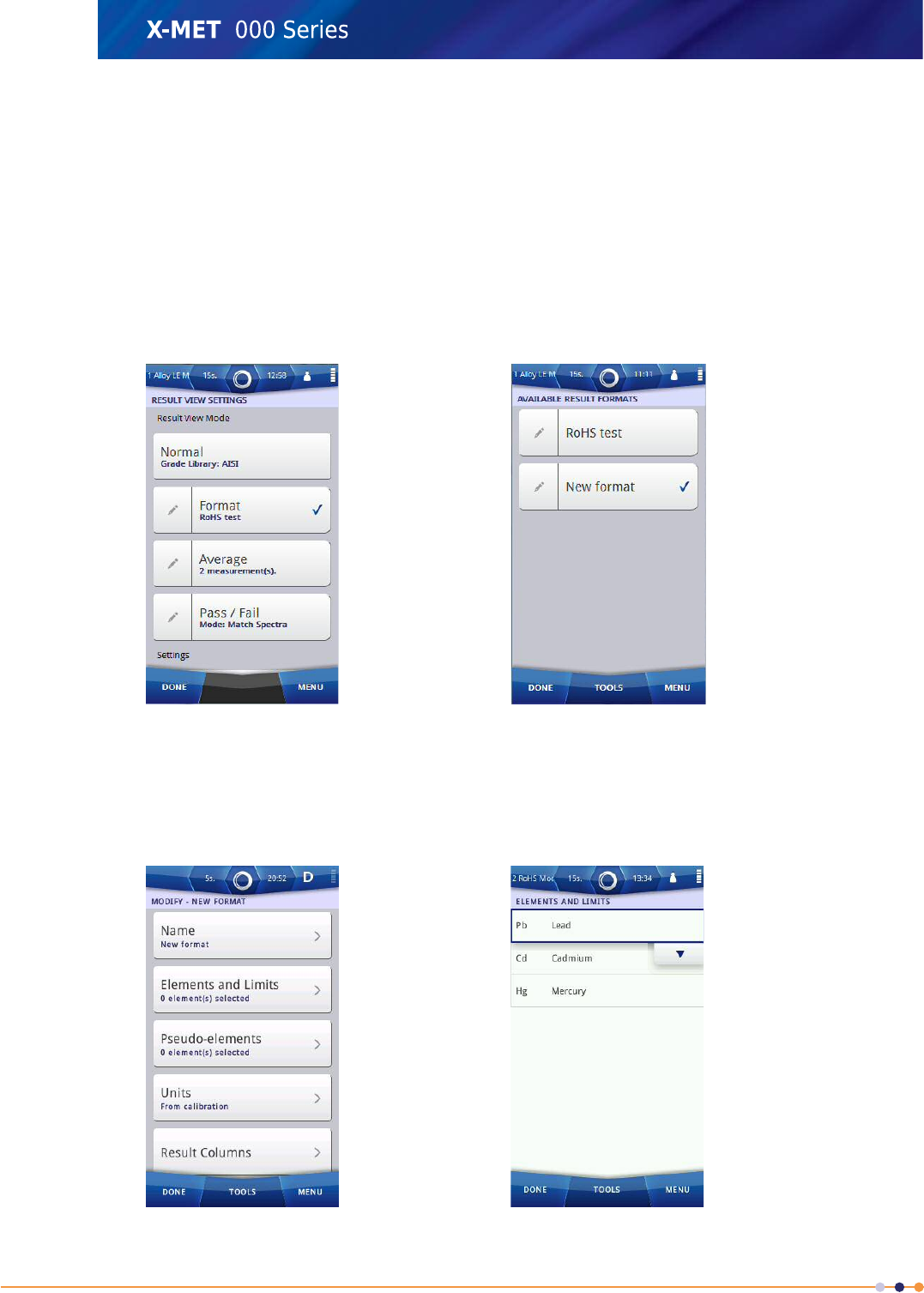
18. Tap Done to return to the Modify - screen.
19. Tap Balance to enable or disable the Balance function.
Balance has a tick against it when enabled.
20. Tap Done again to return to the Available Result Formats screen. Make sure that the applicable
result format has a tick against it.
124
X-MET8000 Series User Manual
8
21. Tap Done again to return to the Result View Settings screen. Make sure that Format has a tick
against it.
22. Tap Done twice again to return to the main screen.
Configure A Results Screen Format
It is necessary to add a custom Results screen format before this procedure. Alarms are only activated
after the Minimum Test Time. Follow these steps to configure the Results screen format.
Select The Results Screen Format
1. Navigate: Menu >Settings >Result View Settings .
The Result View Settings screen appears.
2. Tap Edit (pencil) next to Format.
The Available Result Formats screen appears.
125
X-MET8000 Series User Manual
8
3. Tap Edit (pencil) next to the applicable format.
The Modify - screen appears.
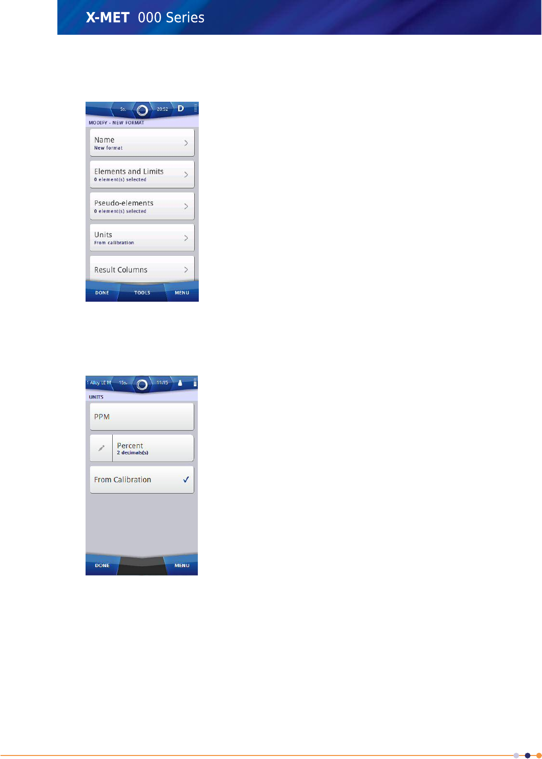
Select The Units
4. Tap Units.
The Units screen appears.
5. Tap one of the following to choose the units for the result format:
•PPM
•Percent
•From Calibration
6. Tap Edit (pencil) next to Percent.
7. Use the numeric keypad to type the number of decimal places to show, and then tap Done to
return to the Units screen.
8. Tap Done to return to the Modify - screen.
126
X-MET8000 Series User Manual
8
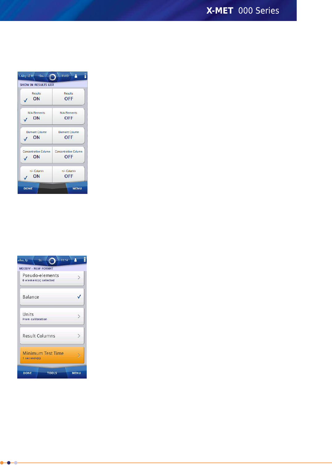
Select The Results Screen Columns
9. Tap Result Columns.
The Show In Results List screen appears.
10. Tap ON or OFF for each of the settings, as applicable, and then tap Done to return to the Modify
- screen.
Set The Minimum Test Time
11. Tap Minimum Test Time.
The Set Minimum Test Time screen appears.
12. Use the numeric keypad to type the minimum test time, and then tap Done to return to the Modify
- screen.
13. Tap Done twice to return to the Result View Settings screen.
14. Tap Done twice again to return to the main screen.
127
X-MET8000 Series User Manual
8
Add Limits And Individual Alarms
It is necessary to add a custom Results screen format before this procedure. Limits are always a
percentage value, even when the Results screen shows the value in parts per million. The +/- Coefficient
is typically an integer between 0 and 5, and has the effect of reducing the low alarm limit, and
increasing the high alarm limit. Follow these steps to add the limits and an alarm on an individual
element.
Select The Results Format
1. Navigate: Menu >Settings >Result View Settings .
The Result View Settings screen appears.
2. Tap Edit (pencil) next to Format.
The Available Result Formats screen appears.
3. Tap Edit (pencil) next to the applicable format.
The Modify - screen appears.
128
X-MET8000 Series User Manual
8
Select The Element
4. Do one of the following:
•Tap Elements And Limits
•Tap Pseudo-elements
Note: The same procedure applies for Elements and Pseudo-elements.
5. Select the element, and then tap: Tools >Set Limits For Selected Element .
The Set Limits - screen appears.
Add The Limits
6. Do one of the following:
•Tap Low Limit
•Tap High Limit
The applicable Limit - screen appears.
129
X-MET8000 Series User Manual
8
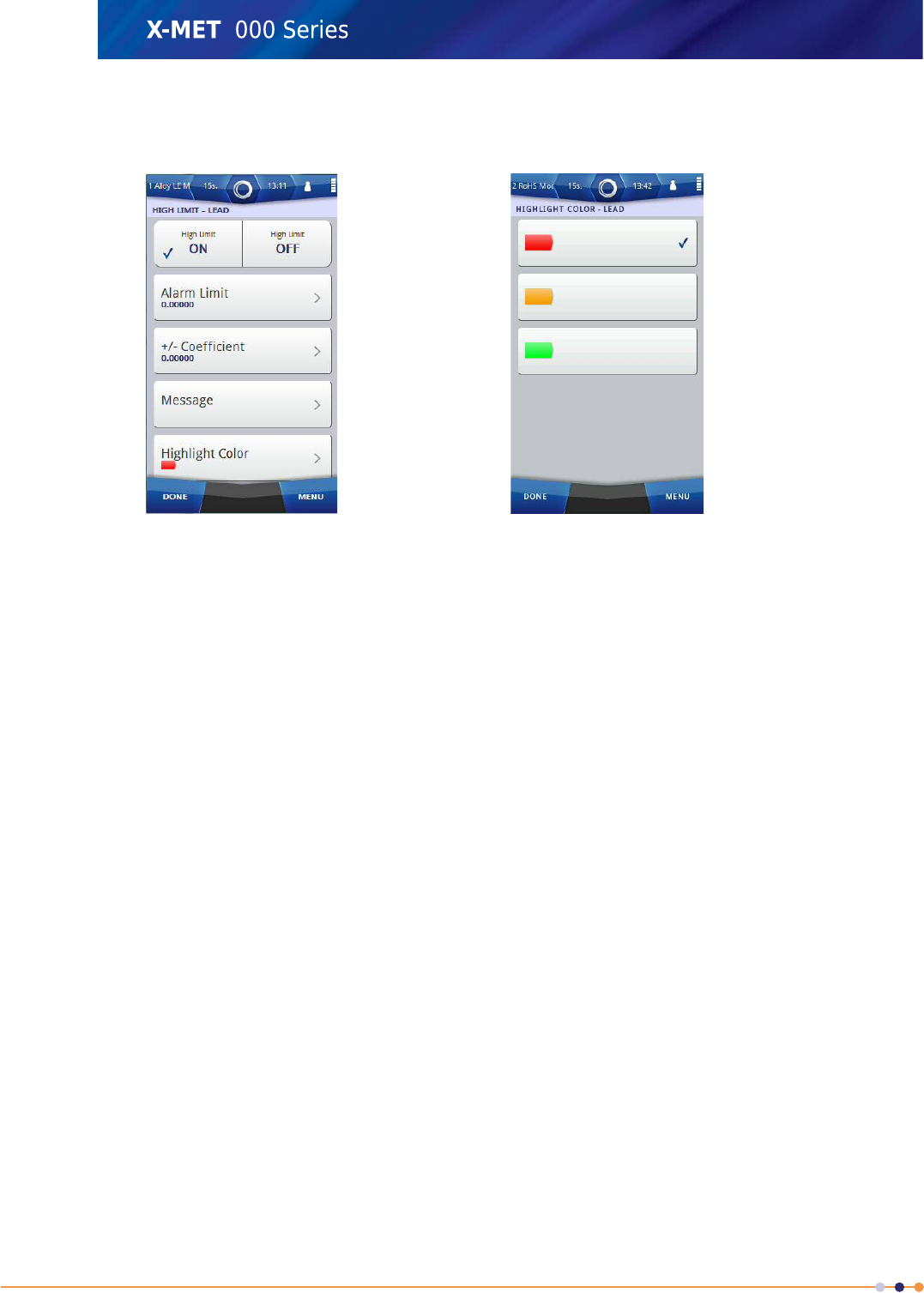
7. Tap the ON tick box.
The Limit - screen changes.
8. Tap Alarm Limit.
9. Use the numeric keypad to type the value for the limit, and then tap Done to return to the Limit -
screen.
10. Tap +/- Coefficient.
11. Use the numeric keypad to type the value for the standard deviation coefficient, and then tap Done
to return to the Limit - screen.
12. Tap Message.
13. Use the virtual keyboard to type the message for the limit, and then tap Done to return to the
Limit - screen.
14. Tap Highlight Colour.
The Highlight Colour - screen appears.
15. Tap one of the colours, and then tap Done to return to the Limit - screen.
130
X-MET8000 Series User Manual
8
16. Tap Done to return to the Set Limits - screen.
Repeat these steps for the other limit, if required.
The Set Limits - screen shows a summary of the limits.
17. Tap Done to return to the Elements And Limits screen.
Repeat these steps for the other elements, if required.
The Elements And Limits screen shows the elements and their limits.
18. Tap Done five times to return to the main screen.
131
X-MET8000 Series User Manual
8
Add Combination Alarms
It is necessary to add a custom Results screen format before this procedure. It is also necessary to
add limits to individual elements. The combination can be a logical OR, or a logical AND. A measurement
trips a logical OR alarm when it trips any of the selected limits, but only trips a logical AND alarm when
it trips all of the selected limits. Follow these steps to add a combination alarm.
Select The Results Format
1. Navigate: Menu >Settings >Result View Settings .
The Result View Settings screen appears.
2. Tap Edit (pencil) next to Format.
The Available Result Formats screen appears.
3. Tap Edit (pencil) next to the applicable format.
The Modify - screen appears.
132
X-MET8000 Series User Manual
8
Select The Element
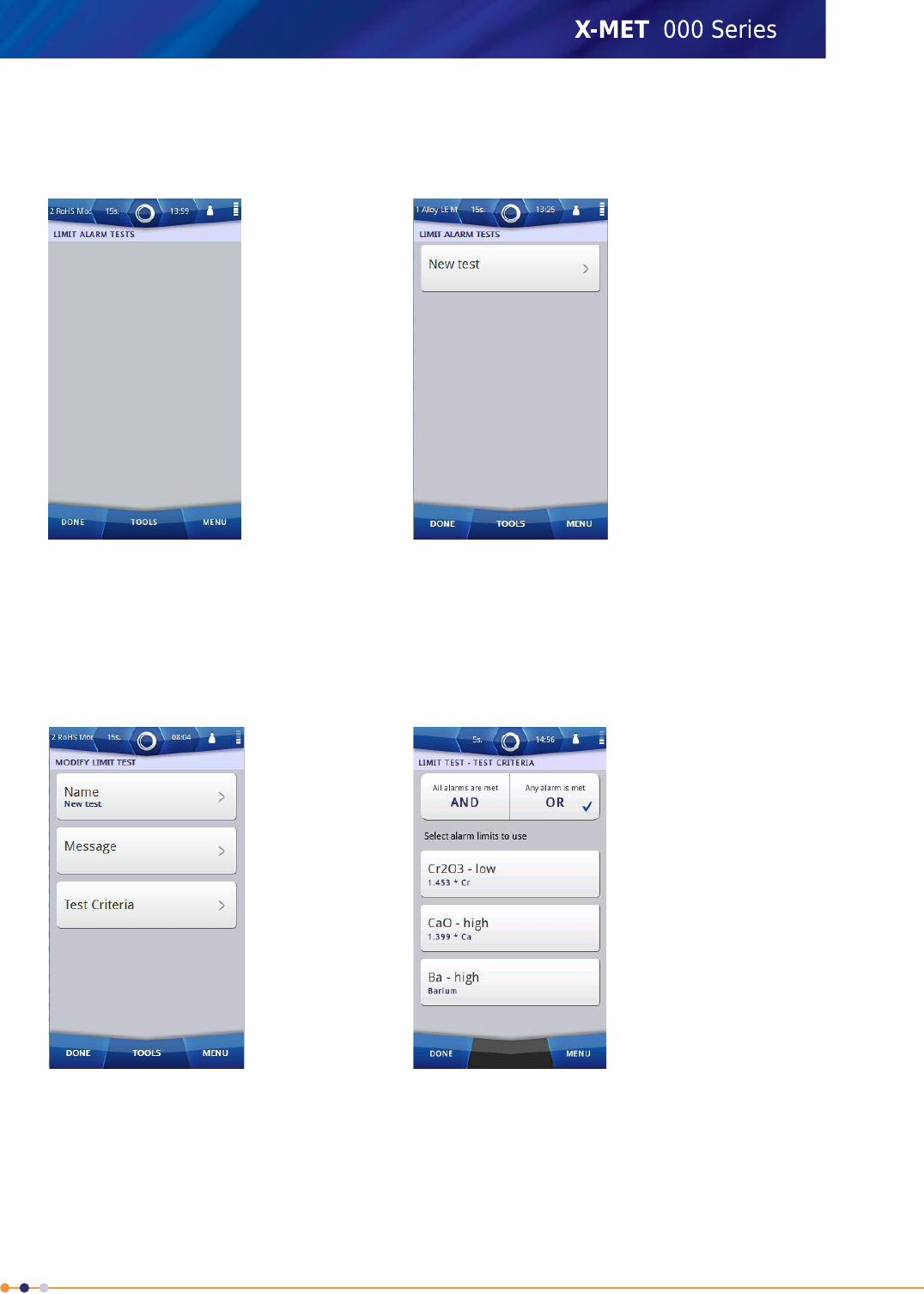
4. Tap: Tools >Create Limit Alarm Tests .
The Limit Alarm Tests screen appears.
Add A Combination Alarm
5. Tap: Tools >Add New .
The Limit Alarm Tests screen has a new combination alarm.
6. Tap New Test.
The Modify Limit Test screen appears.
7. Tap Name.
8. Use the virtual keyboard to type a name for the combination alarm, and then tap Done to return
to the Modify Limit Test screen.
9. Tap Message.
133
X-MET8000 Series User Manual
8

10. Use the virtual keyboard to type the message for the alarm, and then tap Done to return to the
Modify Limit Test screen.
11. Tap Test Criteria.
The Limit Test - Test Criteria screen appears.
It includes all the limits for the individual elements and Pseudo-elements included in the result
format with Pseudo-elements limits presented first.
12. Do one of the following:
•Tap AND
•Tap OR
13. Tap the individual alarms to select them for the combination, and then tap Done to return to the
Modify Limit Test screen.
14. Tap Done to return to the Limit Alarm Tests screen.
This shows the name of the new combination alarm.
15. Tap Done six times to return to the main screen.
About The Grade Table
The X-MET8000 series contains a very extensive grade library based on grades defined by AISI,DIN,JIS
and GB standards. Every user can choose the correct table for his or her own needs. When a
measurement uses a particular method, selecting an applicable grade table provides the possible
grades for the sample. For some materials there are very extensive grade tables, for example iron
and stainless steel, however grade tables are not available for all materials, for example plastics.
It is possible for a supervisor to edit existing grades in the table, and it is possible to add new grades
to a table. It is also possible to delete a grade, and to delete analytes from a grade.
There are three main steps to configure a new grade:
•Add a new grade, and define its name.
•Add analytes to the grade.
•Set the limits for each analyte.
It is also possible to define the precision and the limits that define a match to a grade, and the number
of possible matches. These settings affect all grades for every method. The grade settings are:
•The maximum number of possible grades shown.
•The coefficient for a grade match.
•The limits that define good and possible matches.
Use this table as a guide to adjust these settings.
Harder to matchEasier to matchTypical SettingValue
DecreaseIncrease1.0Grade coefficient
DecreaseIncrease1.0Good match
DecreaseIncrease5.0Possible match
If the grade coefficient is set to 0, the result must be within the grade upper and lower limit to display
the corresponding grade name. If the coefficient is set to n (n= an integer > 0), grade limits are
expanded by n*RMS error. Value 1 is a good starting point.
134
X-MET8000 Series User Manual
8
Good match limit is the threshold limit for Good match. A difference value is calculated how close the
measurement result is compared to the grade specification. If the results of all elements match the
grade specification, the difference is 0.
If the difference is higher than the Good match limit, but lower than the Possible match limit, this is
presented as a Possible match.
Add A Grade To A Grade Table
Follow these steps to add a grade to a grade table, add analytes to the new grade, and set limits for
an analyte.
Add A Grade
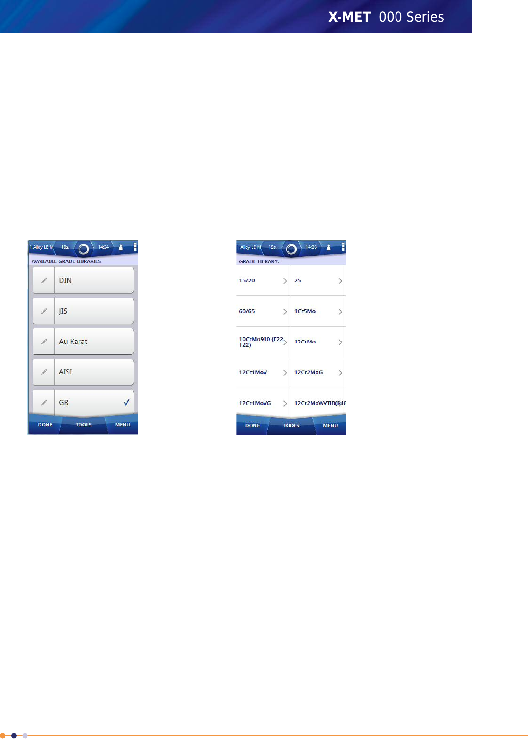
1. Navigate: Menu >Settings >Result View Settings >Grade >Grade Table Editor .
The Available Grade Libraries screen appears.
2. If the list of grade libraries is long, press and slide the list to scroll it up or down, then tap a Grade
Library to select it.
3. Tap Edit (pencil) next to the grade to show the grade library.
The Grade Library screen appears.
4. Tap: Tools >Add Grade .
135
X-MET8000 Series User Manual
8
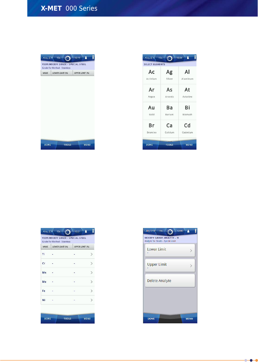
5. Use the virtual keyboard to type the name for the new grade, and then tap Done and scroll down
to the newly created Grade and tap on it.
The View/Modify Grade - screen appears.
Add Analytes To The Grade
6. Tap: Tools >Add Analyte(s) to Grade .
The Select Elements screen appears.
7. Tap an element symbol to select it.
Press and slide, or flick the list to scroll up and down to find an element.
Refer to: Select Elements on page 114 to sort and search the element list.
8. Tap Done to return to the View/Modify Grade - screen.
The grade includes the selected elements.
136
X-MET8000 Series User Manual
8
Set Limits For The Analytes
9. Tap one of the analytes.
The Modify Grade Analyte - screen appears.
10. Do one of the following:
•Tap Lower Limit
•Tap Upper Limit
11. Use the numeric keypad to type the value, and then tap Done.
Repeat these steps for the other limit, if required.
12. Tap Delete Analyte, if required.
Warning dialog box appears. Select OK.This removes the analyte from the grade, and returns to
the View/Modify Grade - screen.
13. Tap Done to return to the View/Modify Grade - screen, and tap Done again to return to the Grade
Library for the Method.
14. Tap Done five times to return to the main screen.
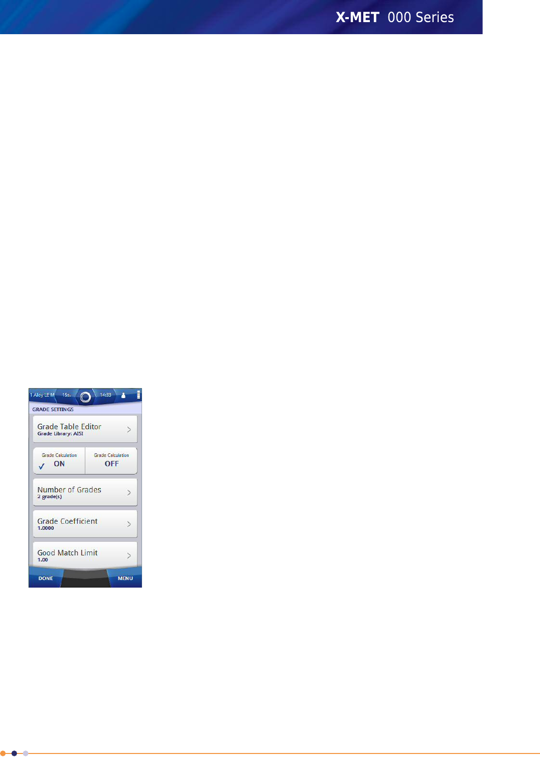
Configure Grade Settings
The grade settings are all numeric values. Follow these steps to configure them.
1. Navigate: Menu >Settings >Result View Settings >Grade .
The Grade Settings screen appears.
2. For Grade Calculation, tap the ON tick box.
When ON is selected, the result screen will show a grade.
3. Do one of the following:
•Tap Number of Grades
•Tap Grade Coefficient
•Tap Good Match Limit
•Tap Possible Match Limit
137
X-MET8000 Series User Manual
8
4. Use the numeric keypad to type the new value, and then tap Done to return to the Grade Settings
screen.
Repeat these steps for other grade settings, if required.
5. Tap Done three times to return to the main screen.
About Pseudo Elements
If the desired Pseudo-element is not listed, the supervisor can create a new one in the global list of
Pseudo-elements.
It is possible for a supervisor to add, edit and remove compounds in the Pseudo-elements settings. A
Pseudo-element can use equations to link any elements and analytes together. For example, in the
cement industry they might use the Lime Saturation Factor to control their process "LSF =
0.715*Ca/(1.784*Si+0.635*Al+0.454*Fe)".
How to calculate an element-to-compound concentration conversion factor:
Element A is displayed as compound AxByCz.
MAis the atomic mass of element A, MBthe atomic mass of element B, etc.
The atomic mass of the compound is: xMA+yMB+zMC.
The conversion factor from A to AxByCzis (xMA+yMB+zMC)/xMA.
Create A New Pseudo Element
Follow these steps to create a new Pseudo-element.
Note: The supervisor will also be able to delete compounds.
1. Navigate: Menu >Settings >Result View Settings .
The Result View Settings screen appears.
138
X-MET8000 Series User Manual
8
2. Scroll down to Settings and Tap Pseudo-elements.
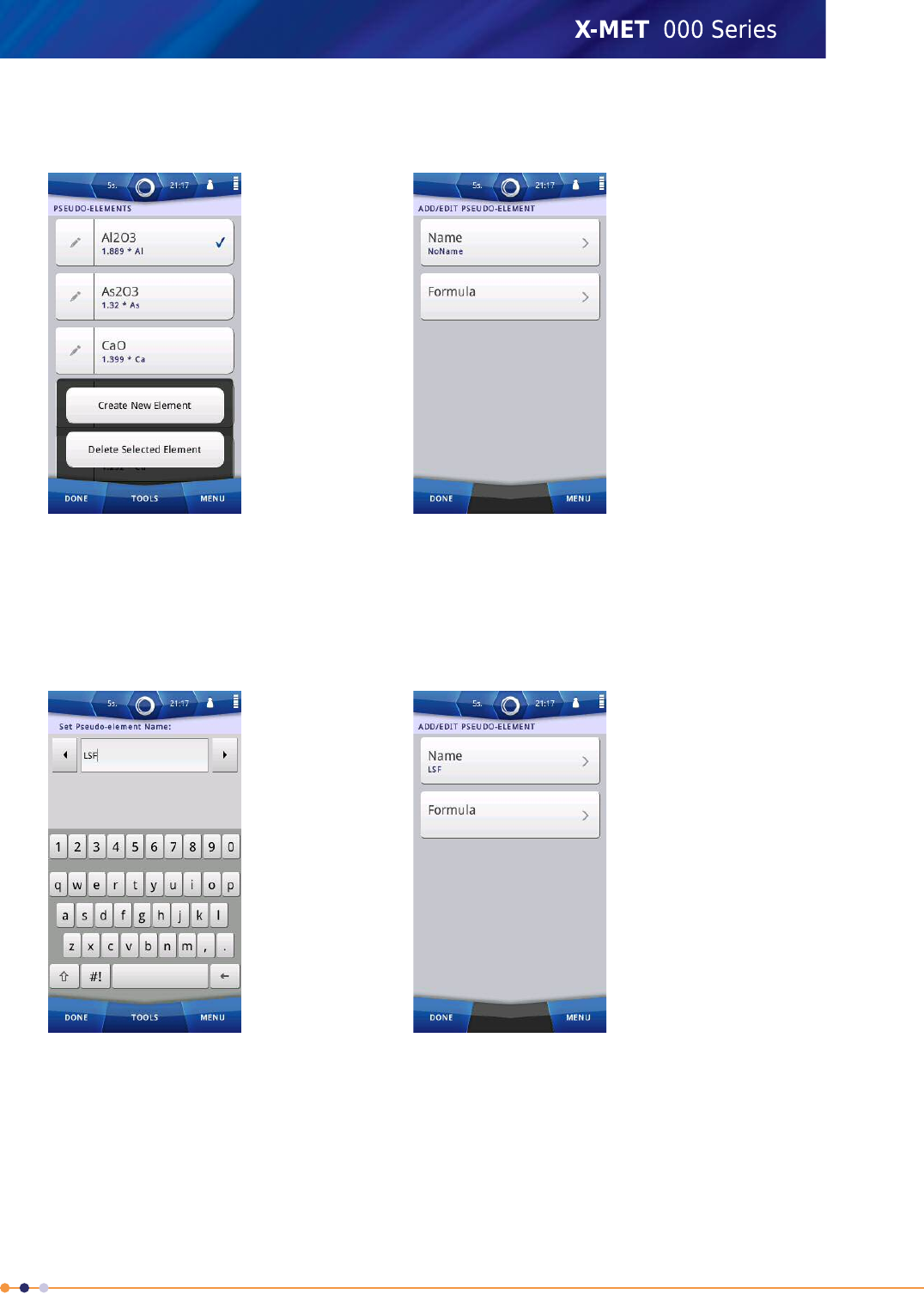
The Available Pseudo-elements screen appears.
3. Tap: Tools >Create New Element .
The Add/Edit Pseudo-element screen appears.
4. Tap Name.
5. Enter an appropriate name using the virtual keyboard and then tap Done to return to the Add/Edit
- screen.
6. Tap Formula to enter a formula for the new Pseudo-element.
139
X-MET8000 Series User Manual
8
7. Enter an appropriate name using the virtual keyboard and then tap Done to return to the Add/Edit
- screen.
The formula can include any elements and analytes and supports basic math functions +-*/^
and ( ).
The formula does not check for elements and analytes so ensure that the correct element or analyte
chemical symbols are used. Errors or division by zero in the formula results in N/A results.
8. Tap Done to return to the Pseudo-elements - screen.
9. Tap Done to return to the Result View Settings - screen.
The new Pseudo-element can now be included in custom result formats.
10. Tap Done twice again to return to the main screen.
140
X-MET8000 Series User Manual
8

Wireless Network Use Cases
The X-MET8000 series can connect to Wi-Fi networks in Managed and Ad hoc mode. A typical use for
Wi-Fi is to connect to a PC. This can allow more than one PC to connect to the X-MET8000 series.
The Wi-Fi connection can be used to transfer reports directly to a shared network resource and for
operation of the X-MET8000 series trough a PC or tablet device using the WEB-interface or VNC. The
Wi-Fi connection can also be used to control the X-MET8000 series remotely using the XAPI protocol.
In a managed network the X-MET8000 series can write reports to shared network folders and print
reports to network printers. In addition the X-MET8000 series can be controlled from any computer
on the local network providing that the IP address for the X-MET8000 series is known.
This manual will in detail explain how to connect the X-MET8000 series to a Wi-Fi network, enable
shared folders for file transfer and connect to the X-MET8000 series using a Wi-Fi enabled computer
or tablet.
Trough an ad hoc network connection it is possible to remotely access and control the X-MET8000
series using an WEB-browser or VNC and from the X-MET8000 series use shared folders and printers
physically connected to the computer providing the ad hoc network.
Note that shared network resources may not work in ad hoc mode unless the resources are located
on the device providing the ad hoc network.
The X-MET8000 series can be remotely controlled trough a VNC connection and using most common
WEB browsers. This manual includes instructions on how to setup and control the X-MET8000 series
using a WEB browser running on a PC and trough a VNC-connection from a PC and an iPad.
WEB browsers on mobile devices may not be fully compatible with the X-MET8000 series web interface,
some features might not work properly if used with a mobile device web browser.
Multiple Wi-Fi connected X-MET8000 series devices can be controlled from a single computer using
tabs in the WEB browser, one tab for each X-MET8000 series device.
Using the XAPI interface and a Wi-Fi connection multiple X-MET8000 series devices can be used for
automated operation with a minimum of additional equipment and infrastructure.
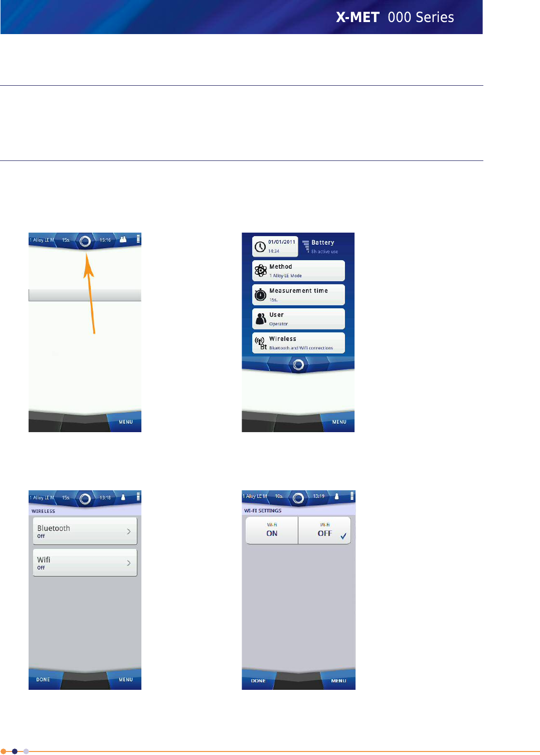
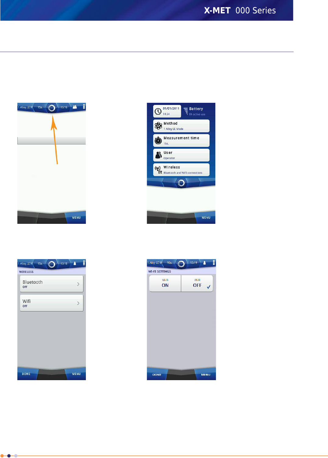
Wireless Connections
The X-MET8000 series can connect to Bluetooth and Wi-Fi networks. Both networks are switched off
by default. A typical use for Bluetooth would be to connect to a precision GPS receiver for mining
applications, and it is possible to check the GPS information from the X-MET8000 series. A typical use
for Wi-Fi is to connect to a PC. This can allow more than one PC to connect to the X-MET8000 series.
The Wi-Fi connection can be to a broadcast network or to a hidden network. For a broadcast network,
it can be necessary to know the passkey. For a hidden network, it is necessary to know the SSID.
Hidden networks can be either managed or ad-hoc. Managed networks can use either WPA or WPA2
Personal encryption, and ad hoc networks can use WPA None encryption. If a hidden network uses
encryption, it is necessary to know the passkey. The network administrator will know the type of
network in use, and can provide the SSID and passkey, as applicable.
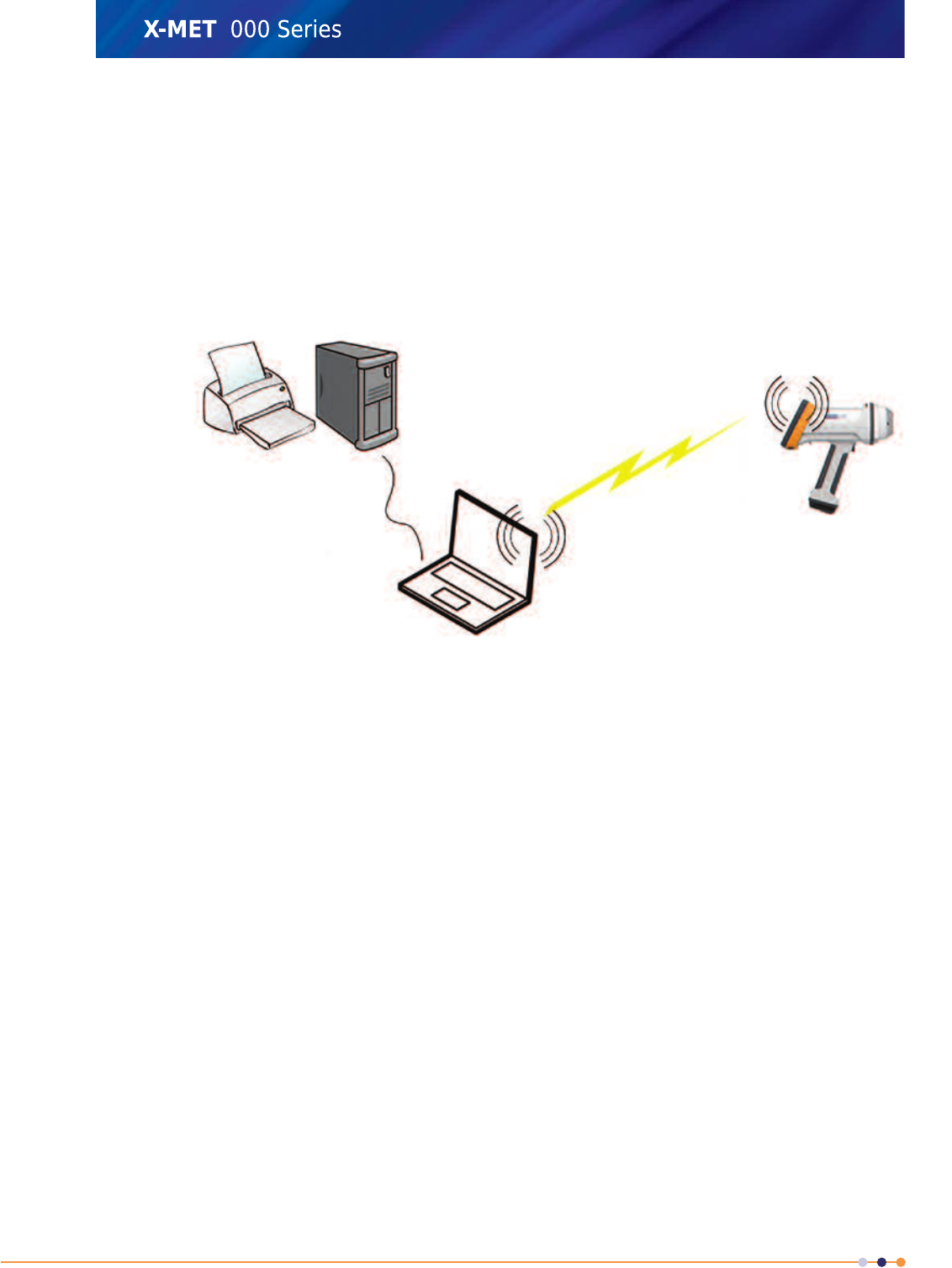
An ad hoc Wi-Fi network is a decentralized type of wireless network. The network is ad hoc because
it does not rely on a pre existing infrastructure, such as access points in managed wireless networks.
Network shared folders and printer will most likely not work trough an ad hoc network
141
X-MET8000 Series User Manual
8
A managed Wi-Fi network utilizes access points providing wireless access to the network infrastructure
including shared folders and printers
Most common full featured web browsers i.e. IE, Mozilla and Chrome will work with the X-MET8000
series web user interface and are platform and X-MET8000 series software version independent.
Many mobile devices use web browsers optimized for mobile web browsing, these might not include
all features required by the X-MET8000 series web GUI. Multiple X-MET8000 series devices running
different software versions can be operated simultaneously using tabs in the web browser.
Wi-Fi ad hoc network topology
The laptop provides the Wi-Fi network in ad hoc mode and the X-MET8000 series connects directly to
the laptop. Network resources might not be accessible from the X-MET8000 series.
142
X-MET8000 Series User Manual
8
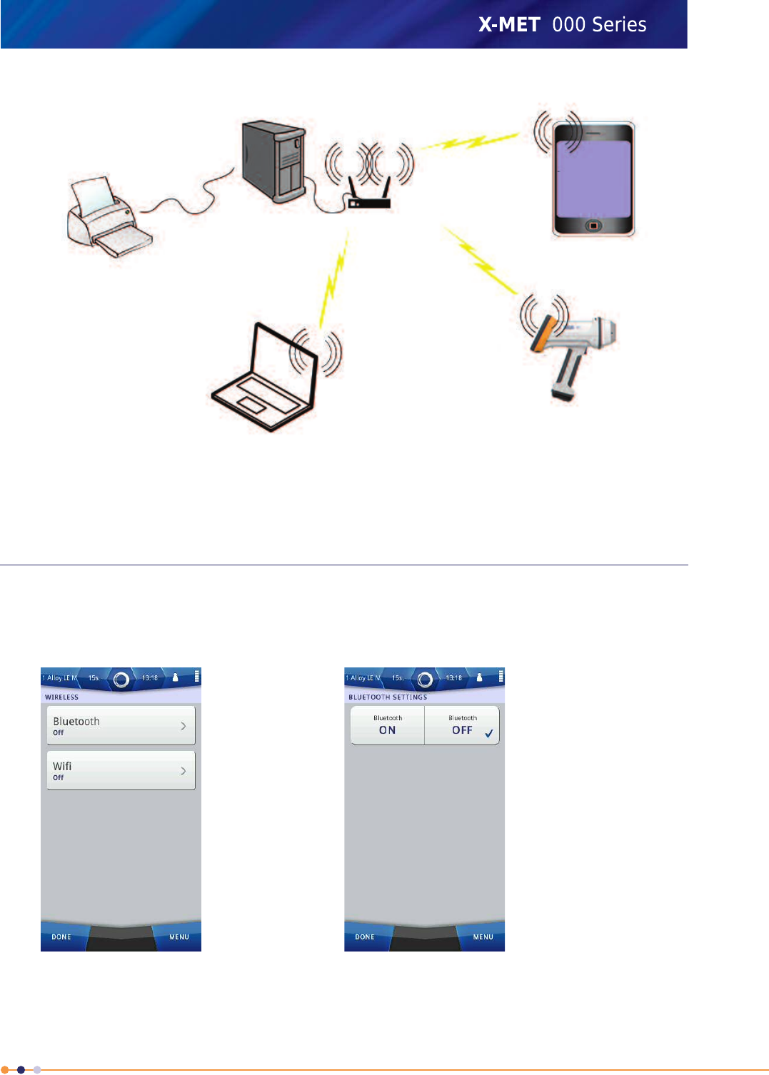
Wi-Fi managed network topology
In managed networks existing infrastructure like routers and switches connects the clients to the
network, shared resources are accessible from all network connected clients.
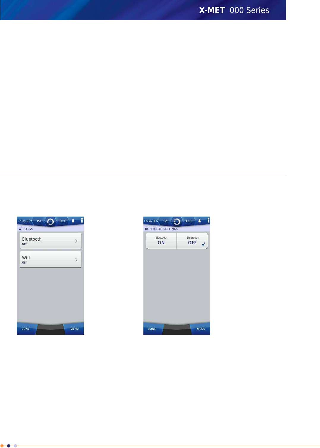
Add A Bluetooth Connection
Follow these steps to connect to a Bluetooth device.
1. Navigate: Status Bar >Wireless .
The Wireless screen appears.
143
X-MET8000 Series User Manual
8
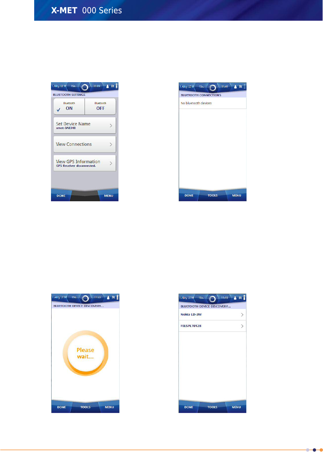
2. Tap Bluetooth.
The Bluetooth Settings screen appears.
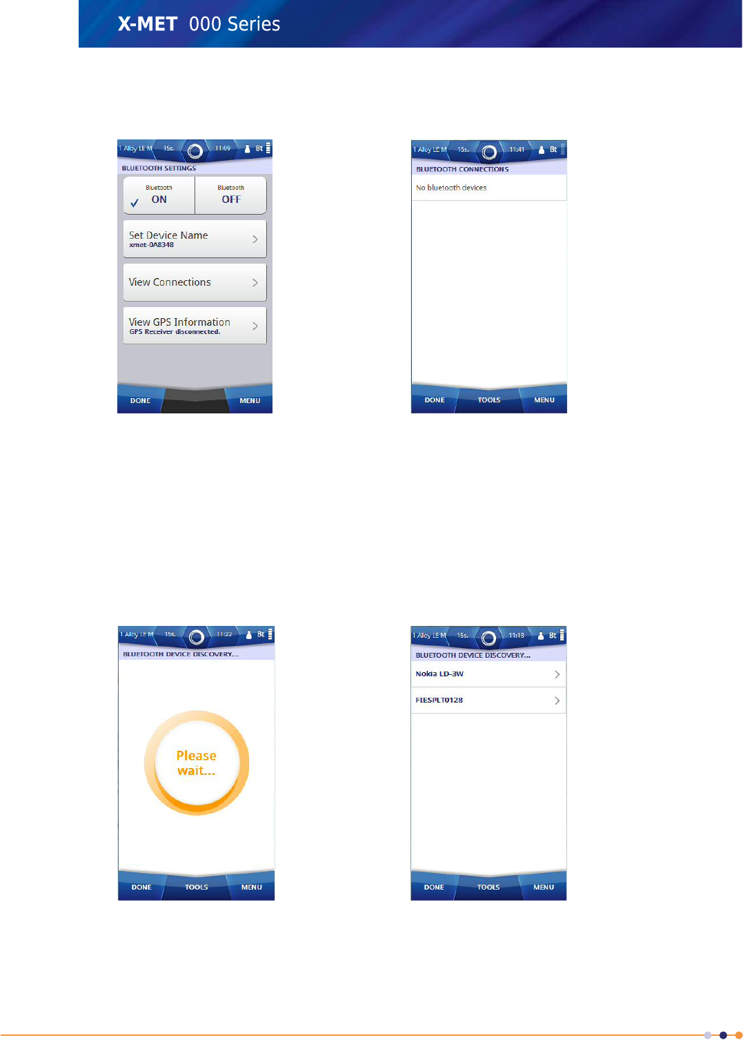
3. Tap the ON tick box.
The Bluetooth Settings screen changes.
4. Tap Set Device Name.
5. Use the virtual keyboard to type an applicable name, and then tap Done to return to the Bluetooth
Settings screen.
6. Tap View Connections.
The Bluetooth Connections screen appears.
7. Tap: Tools >Discover New Devices .
The Bluetooth Device Discovery screen appears, and a search for the Bluetooth devices begins.
When the search is complete, the screen shows the available Bluetooth devices.
144
X-MET8000 Series User Manual
8
8. If necessary, tap: Tools >Discover Again .
Another search for the Bluetooth devices begins, and the Bluetooth Device Discovery screen
updates.
9. Tap on one of the discovered bluetooth devices.
The Set Pin Code for Bluetooth Device screen appears.
10. Enter the correct Pin Code.
11. Tap Done twice to return to the Bluetooth Connections screen.
The Bluetooth device is added to the Bluetooth Connections screen.
12. Tap on the newly added bluetooth device and select Tools and choose one of the applicable options.
The Bluetooth Connections screen updates.
13. Tap Done to return to the Bluetooth Settings screen.
14. Tap Done twice again to return to the main screen.
Add A Bluetooth Keyboard
Follow these steps to add a Bluetooth keyboard directly to the X-MET8000 series.
1. Navigate: Status Bar >Wireless .
The Wireless screen appears.
2. Tap Bluetooth.
The Bluetooth Settings screen appears.
145
X-MET8000 Series User Manual
8
3. Tap the ON tick box.
The Bluetooth Settings screen changes.
4. Tap Set Device Name.
5. Use the virtual keyboard to type an applicable name, and then tap Done to return to the Bluetooth
Settings screen.
6. Tap View Connections.
The Bluetooth Connections screen appears.
7. Tap: Tools >Discover New Devices .
The Bluetooth Device Discovery screen appears, and a search for the Bluetooth devices begins.
When the search is complete, the screen shows the available Bluetooth devices.
8. If necessary, tap: Tools >Discover Again .
Another search for the Bluetooth devices begins, and the Bluetooth Device Discovery screen
updates.
146
X-MET8000 Series User Manual
8
9. Tap on the discovered Bluetooth keyboard.
The Set Pin Code for Bluetooth Device screen appears.
10. Enter the correct Pin Code, verify the correct code from the keyboard manual if necessary.
Tip: If the password does not work, try typing the passkey on the touch screen, then type the same
passkey and press <ENTER> on the Bluetooth keyboard.
Please refer to the keyboard manual for additional information on pairing the keyboard.
11. Tap Done twice to return to the Bluetooth Connections screen.
The Bluetooth keyboard is added to the Bluetooth Connections screen.
12. Tap on the newly added bluetooth keyboard and select Tools >Connect To Input .
The Bluetooth Connections screen updates. An information message is displayed informing that
the keyboard is connected.
13. Tap Done to return to the Bluetooth Settings screen.
14. Tap Done twice again to return to the main screen.
The Bluetooth keyboard can no be used as input device in all fields where text or numeric input is
applicable.
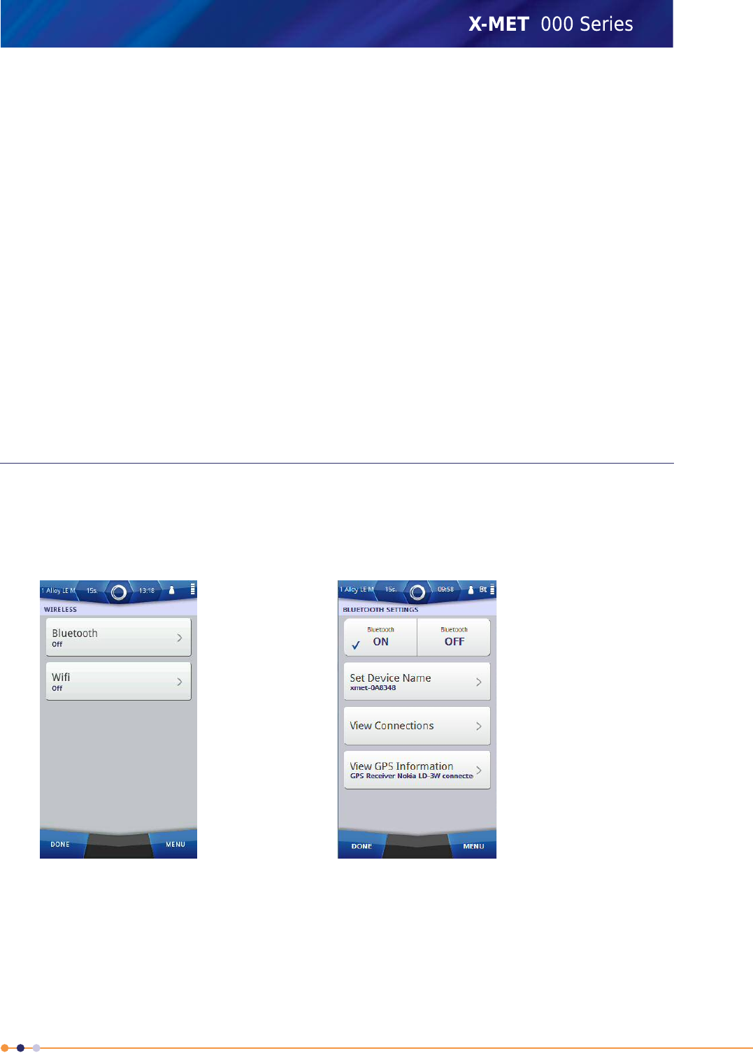
Check GPS Information
Once a Bluetooth connection is made to the GPS receiver, it is possible to check the GPS position data
and satellite information. Follow these steps to check the GPS information.
1. Navigate: Status Bar >Wireless
The Wireless screen appears.
2. Tap Bluetooth.
The Bluetooth Settings screen appears.
147
X-MET8000 Series User Manual
8
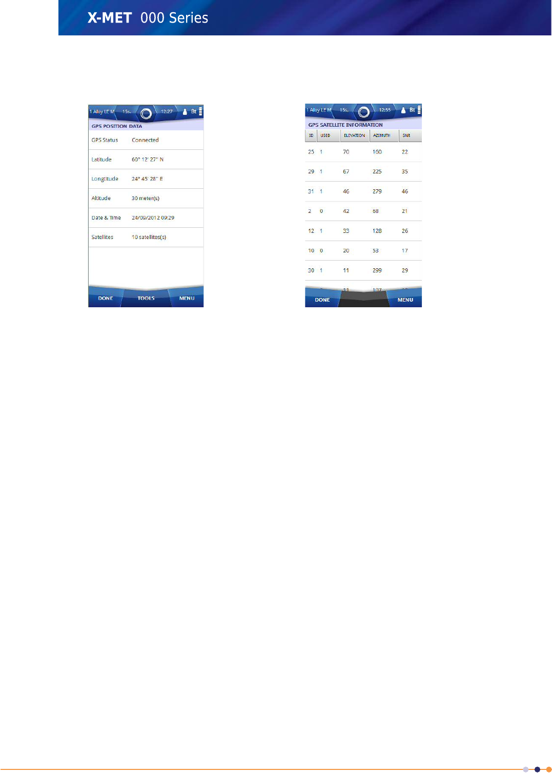
3. Tap View GPS Information.
The GPS Position Data screen appears.
4. Tap: Tools >Refresh Now to refresh the GPS Position Data.
5. Tap: Tools >View Satellites
The GPS Satellite Information screen appears.
6. Tap Done to return to the GPS Position Data screen.
7. Tap Done to return to the Bluetooth Settings screen.
8. Tap Done twice again to return to the main screen.
148
X-MET8000 Series User Manual
8
Connect the X-MET8000 series to a company network
The procedure may differ depending on the network security level and server versions used. If the
network utilizes device based authentication or you are unable to connect to the network using the
following steps, please contact your local network administrator for support.
Add A Broadcast Wi-Fi Connection
Follow these steps to connect to a broadcast Wi-Fi network.
1. Navigate: Status Bar >Wireless .
The Wireless screen appears.
2. Tap Wi-Fi.
The Wi-Fi Settings screen appears.
149
X-MET8000 Series User Manual
8
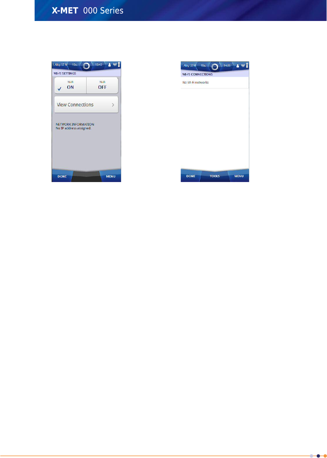
3. Tap the ON tick box.
The Wi-Fi Settings screen changes.
4. Tap View Connections.
The Wi-Fi Connections screen appears.
150
X-MET8000 Series User Manual
8
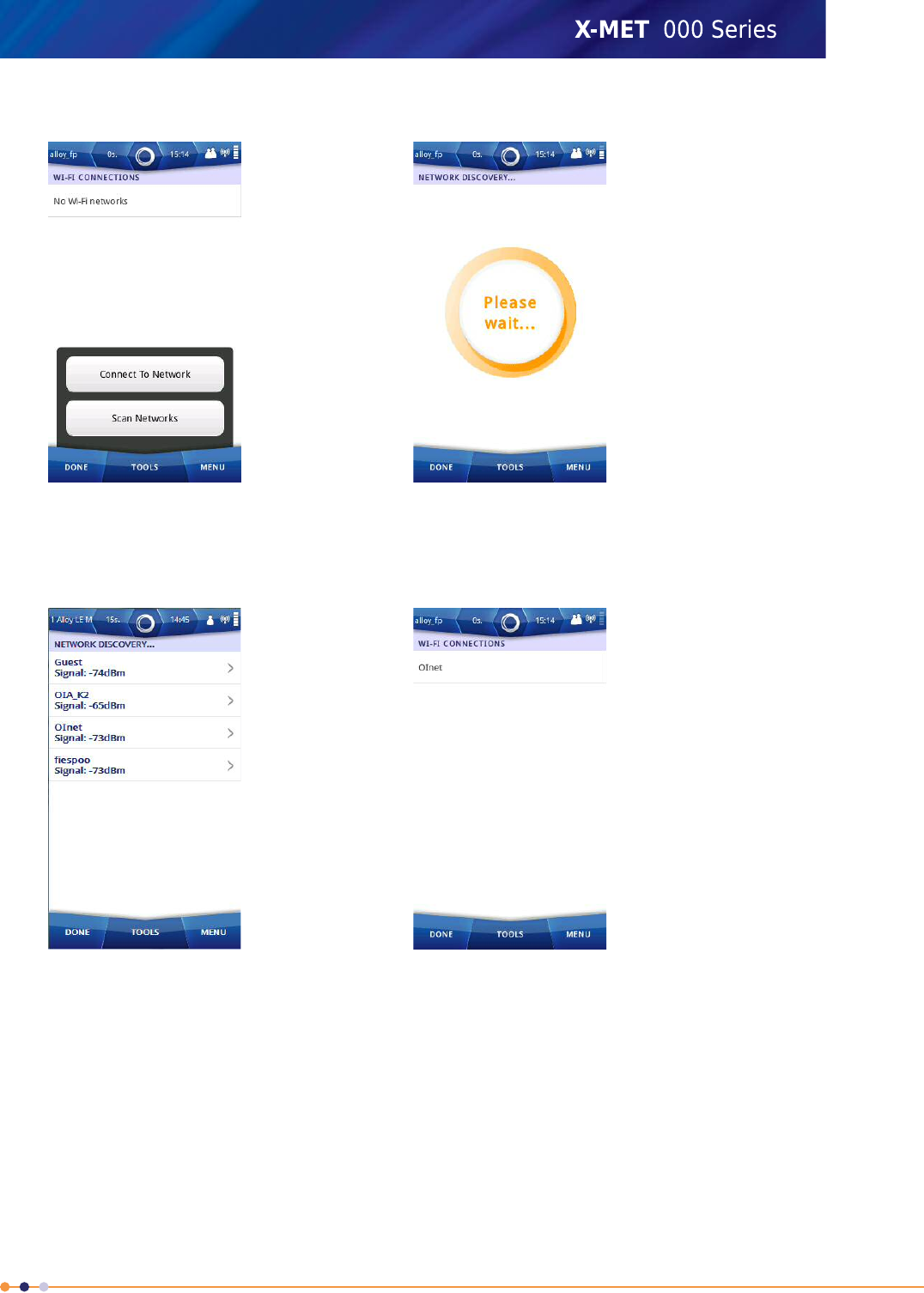
5. Tap: Tools >Scan Networks .
The Network Discovery screen appears, and a search for Wi-Fi networks begins.
When the search is complete, the screen shows the available Wi-Fi networks.
The list is ordered with the strongest signals at the top.
6. If necessary, tap: Tools >Scan Again .
Another search for Wi-Fi networks begins, and the Network Discovery screen is refreshed.
7. Tap one of the Wi-Fi networks.
151
X-MET8000 Series User Manual
8
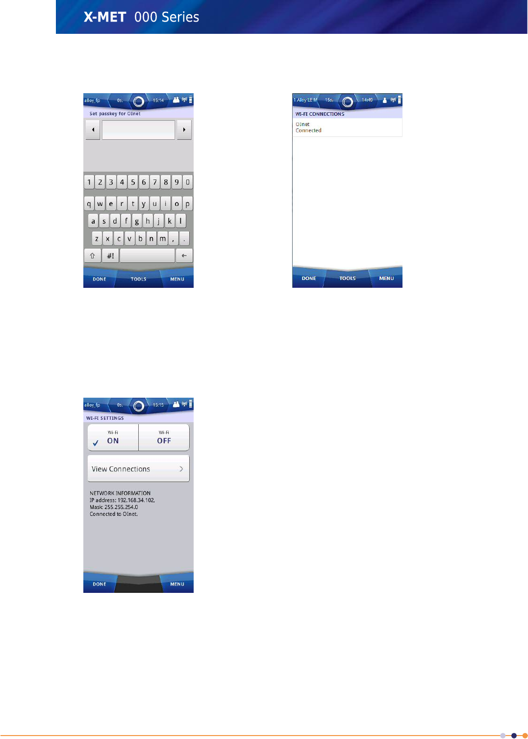
8. If the selected Wi-Fi network requires a passkey, use the virtual keyboard to type the passkey for
the network, then tap Done to return to the Network Discovery screen.
9. Tap Done to return to the Wi-Fi Connections screen.
This shows the active Wi-Fi connection.
10. Tap Done to return to the Wi-Fi Settings screen.
Wait until the Network Information IP address and Mask update in the Wi-Fi Settings screen. The
updated IP address can be used to access the X-MET8000 series from the other computers that
are in the same network.
11. Tap Done twice to exit the Wi-Fi Settings screen.
152
X-MET8000 Series User Manual
8
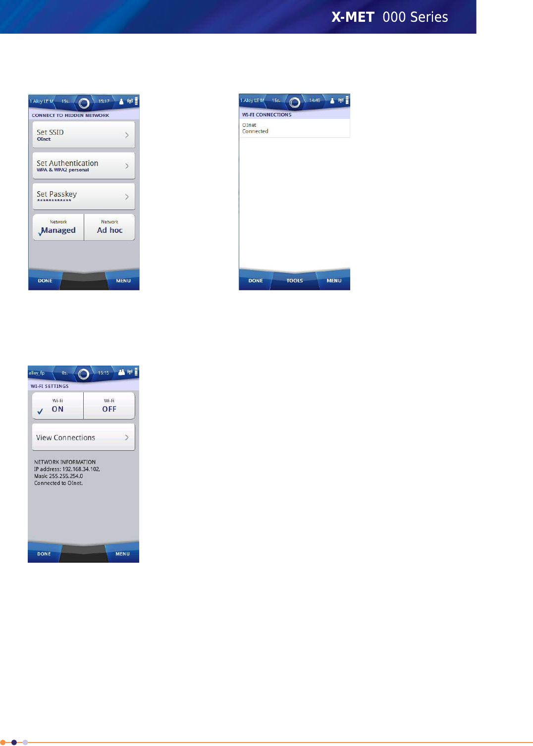
Add A Hidden Wi-Fi Connection
Follow these steps to connect to a hidden Wi-Fi network. Managed networks can use either WPA or
WPA2 Personal encryption, and ad hoc networks can use WPA None encryption.
1. Navigate: Status Bar >Wireless .
The Wireless screen appears.
2. Tap Wi-Fi.
The Wi-Fi Settings screen appears.
153
X-MET8000 Series User Manual
8
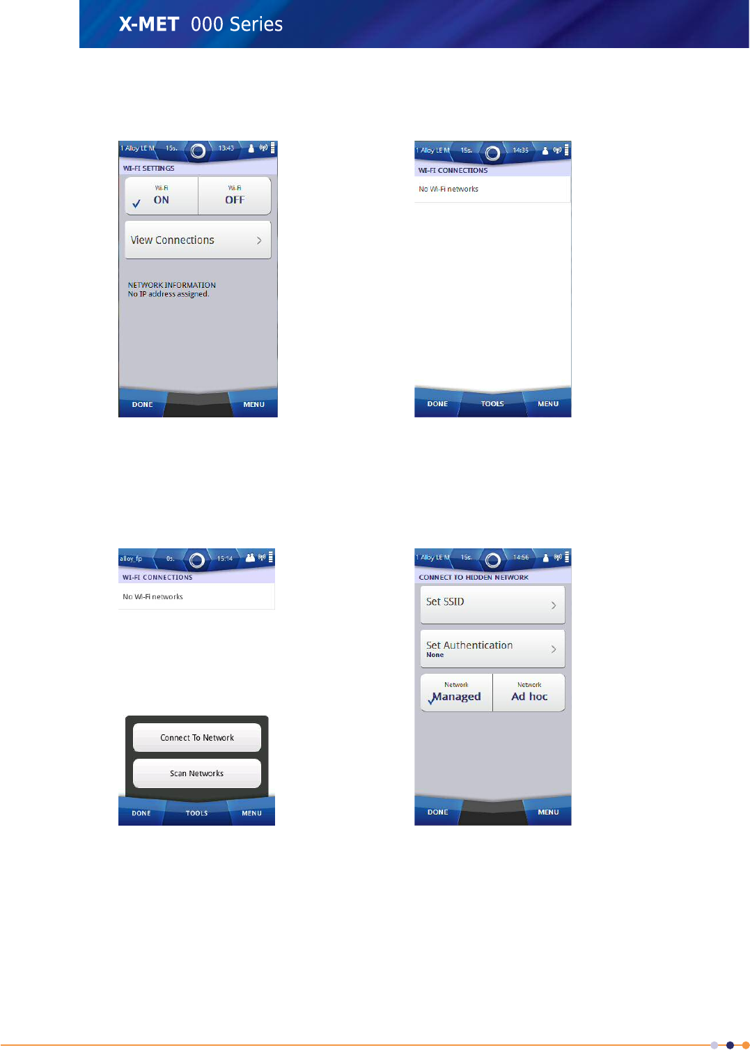
3. Tap the ON tick box.
The Wi-Fi Settings screen changes.
4. Tap View Connections.
The Wi-Fi Connections screen appears.
5. Tap: Tools >Connect To Network .
The Connect To Hidden Network screen appears.
6. Tap Set SSID.
154
X-MET8000 Series User Manual
8
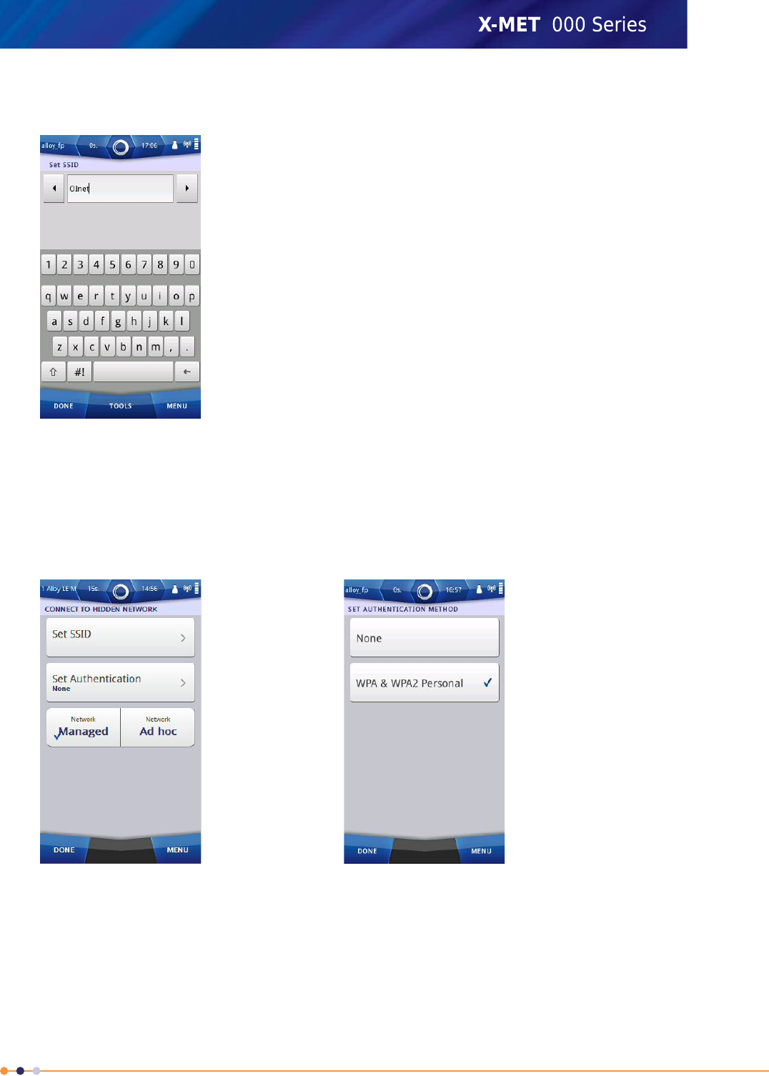
7. Use the virtual keyboard to type the SSID, and then tap Done to return to the Connect To Hidden
Network screen.
8. Do one of the following:
•Tap Managed
•Tap Ad Hoc
9. Tap Set Authentication.
The Set Authentication Method screen appears.
155
X-MET8000 Series User Manual
8
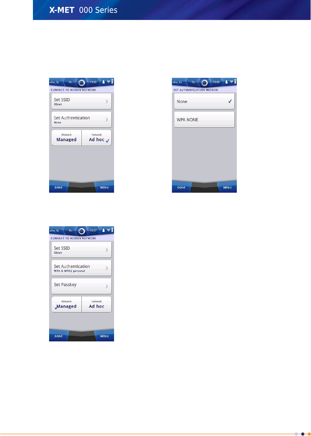
10. Do one of the following:
•Tap None
•Tap WPA & WPA2 Personal
For an ad hoc network, the second choice is WPA None.
11. Tap Done to return to the Connect To Hidden Network screen.
The Connect To Hidden Network screen changes.
12. Tap Set Passkey.
156
X-MET8000 Series User Manual
8
13. Use the virtual keyboard to type the passkey for the network, and then tap Done to return to the
Connect To Hidden Network screen.
14. Tap Done to return to the Wi-Fi Settings screen.
Wait until the Network Information IP address and Mask update in the Wi-Fi Settings screen. The
updated IP address can be used to access the X-MET8000 series from the other computers that
are in the same network.
15. Tap Done twice to exit the Wi-Fi Settings screen.
157
X-MET8000 Series User Manual
8
Wireless Printing
The X-MET8000 series supports printing Reports directly to a network connected printer over a Wi-Fi
connection. Setup wireless printing using the following instructions.
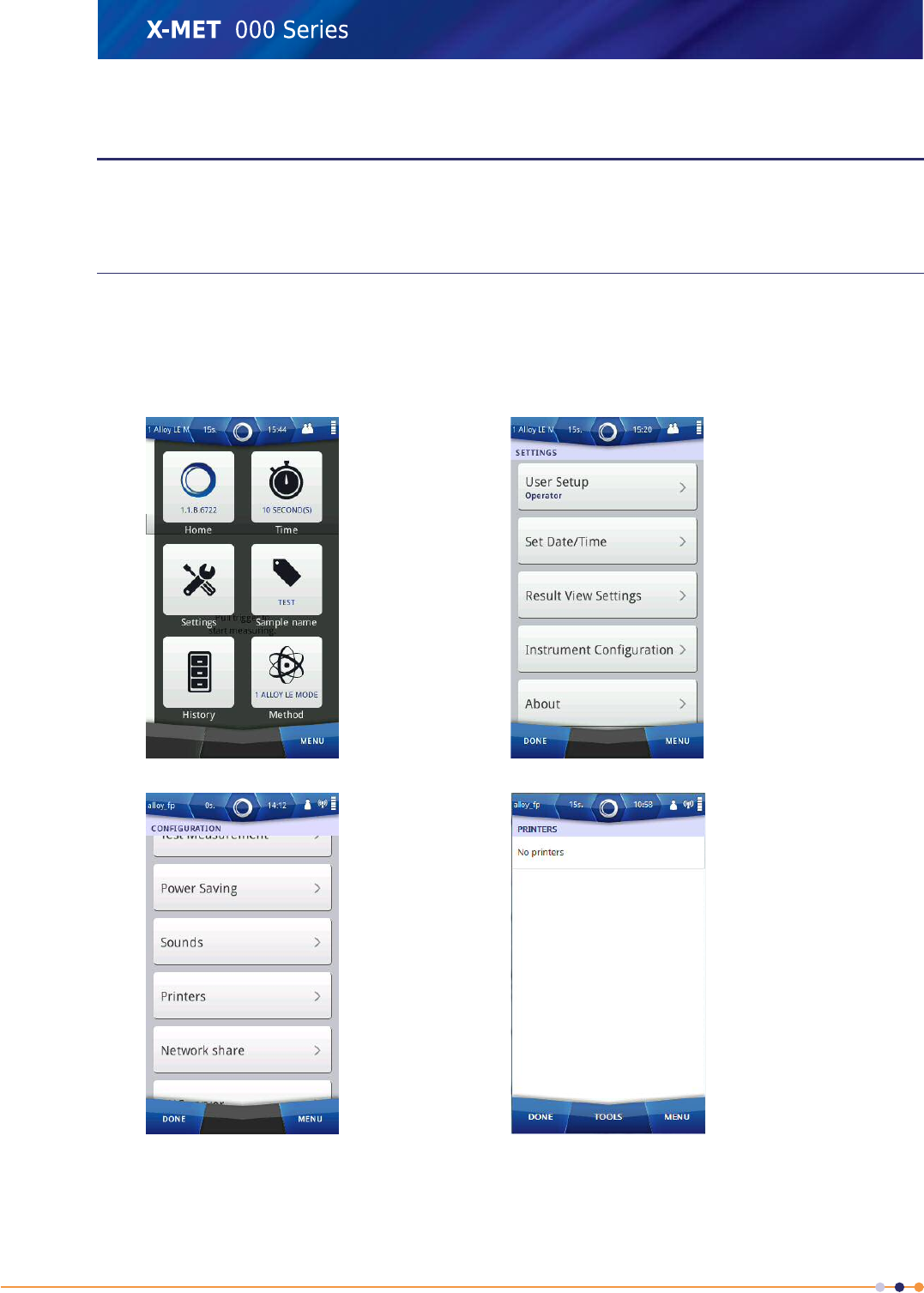
Configure A Printer
It is necessary to connect the X-MET8000 series device to a Wi-Fi network before configuring a printer.
Follow the steps below to configure a printer.
The supervisor must configure network printers.
1. Navigate: Menu >Settings >Instrument Configuration >Printers .
The Printers screen appears.
158
X-MET8000 Series User Manual
8
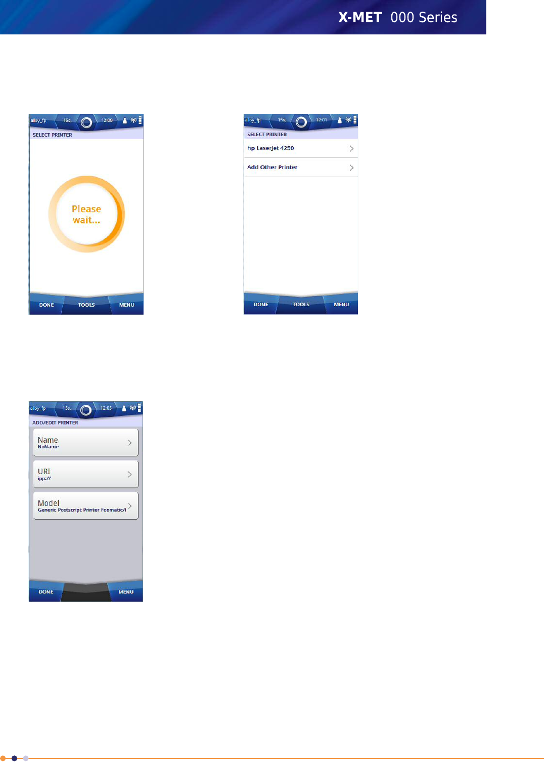
2. Tap Tools >Add Printer .
The Select Printer screen appears and a search begins for the network printers. When the search
is complete, the screen shows the available Network Printers and Add Other Printer.
3. If necessary, scan again by selecting Tools >Scan Again .
4. Tap either on the found Network Printers or Add Other Printer to input the printer information
manually.
The Add/Edit Printer screen appears.
5. Do the following:
•Tap Name
The Printer name can be any text, it is used to identity a printer when multiple printers are
configured in the device.
•Tap URI
The system administrator will need to provide the IPP address for the printer.
159
X-MET8000 Series User Manual
8

6. Use the virtual keyboard to type the new value, and tap Done to return to the Add/Edit Printer
screen.
7. It is not necessary to change Model as most of the printers work with a default generic postscript
driver which is available in the device. If the user wants to install a different PPD driver from a USB
memory device, then tap Model .
The Printer Model screen appears.
8. Tap Maker to select the applicable maker. Tap Done to return to the Printer model screen.
The Printer Model screen updates with the new values.
9. Tap User PPD to install the PPD file for the printer from the memory stick.
10. Tap Done.
The Information dialog box appears.
11. Tap OK to return to the Select Printer screen.
12. Tap Done 4 times to return to the main screen.
160
X-MET8000 Series User Manual
8
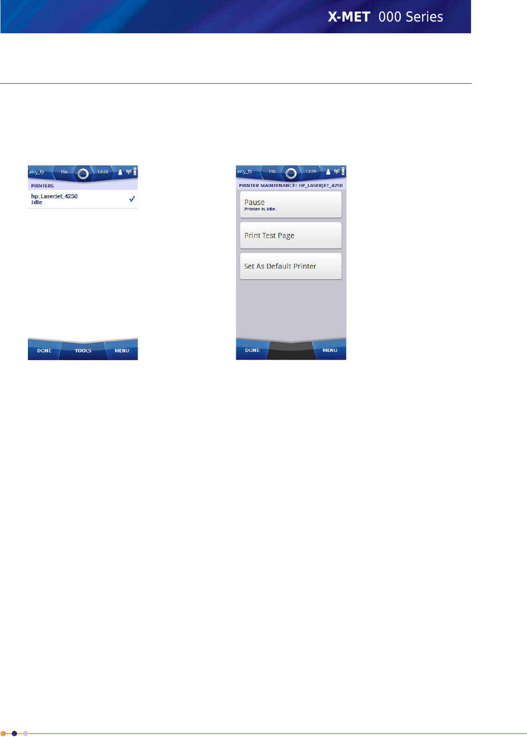
Print A Test Page
It is necessary to configure a printer before printing a test page. Follow the steps below to print a test
page.
1. Navigate: Menu >Settings >Instrument Configuration >Printers .
The Printers screen appears.
2. Select a printer and tap Tools >Maintenance Selected .
The Printer Maintenance screen appears.
3. Tap Print Test Page.
The Information dialog box appears.
4. Tap OK to return to the Printer Maintenance screen.
5. If the printing of the test page is successful, set the printer as the default printer by selecting Set
As Default Printer in the Printer Maintenance screen.
6. Tap Done 4 times to return to the main screen.
161
X-MET8000 Series User Manual
8

Generate Report to Printer
The Supervisor must configure a network printer in the device in order to generate reports directly
on a printer, and must connect the device to the same WiFi network as the one to which the network
printer is connected. Please refer to the Supervisor manual to set this up. Follow the below steps to
generate report to printer.
1. Tap Menu, and then tap History.
The History screen appears.
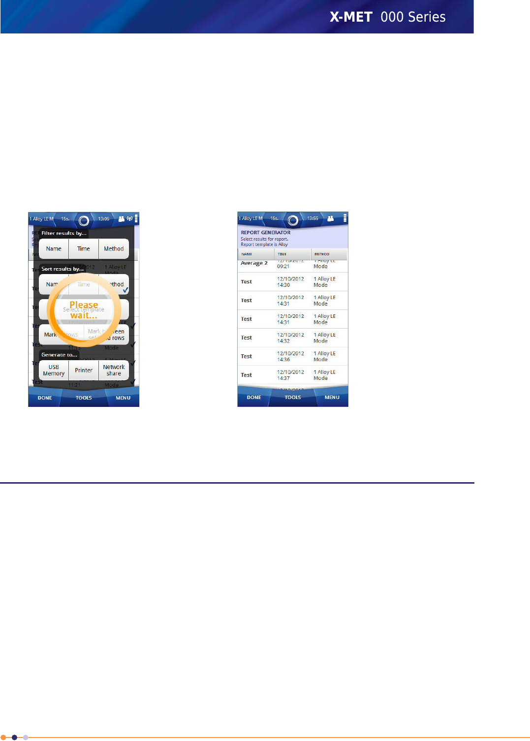
2. Tap: Tools >Generate Report
The Report Generator screen appears.
3. Tap: Tools >Select Template
The Select Report Template screen appears with the default report template list and also user
defined templates which were created in the Web GUI.
162
X-MET8000 Series User Manual
8
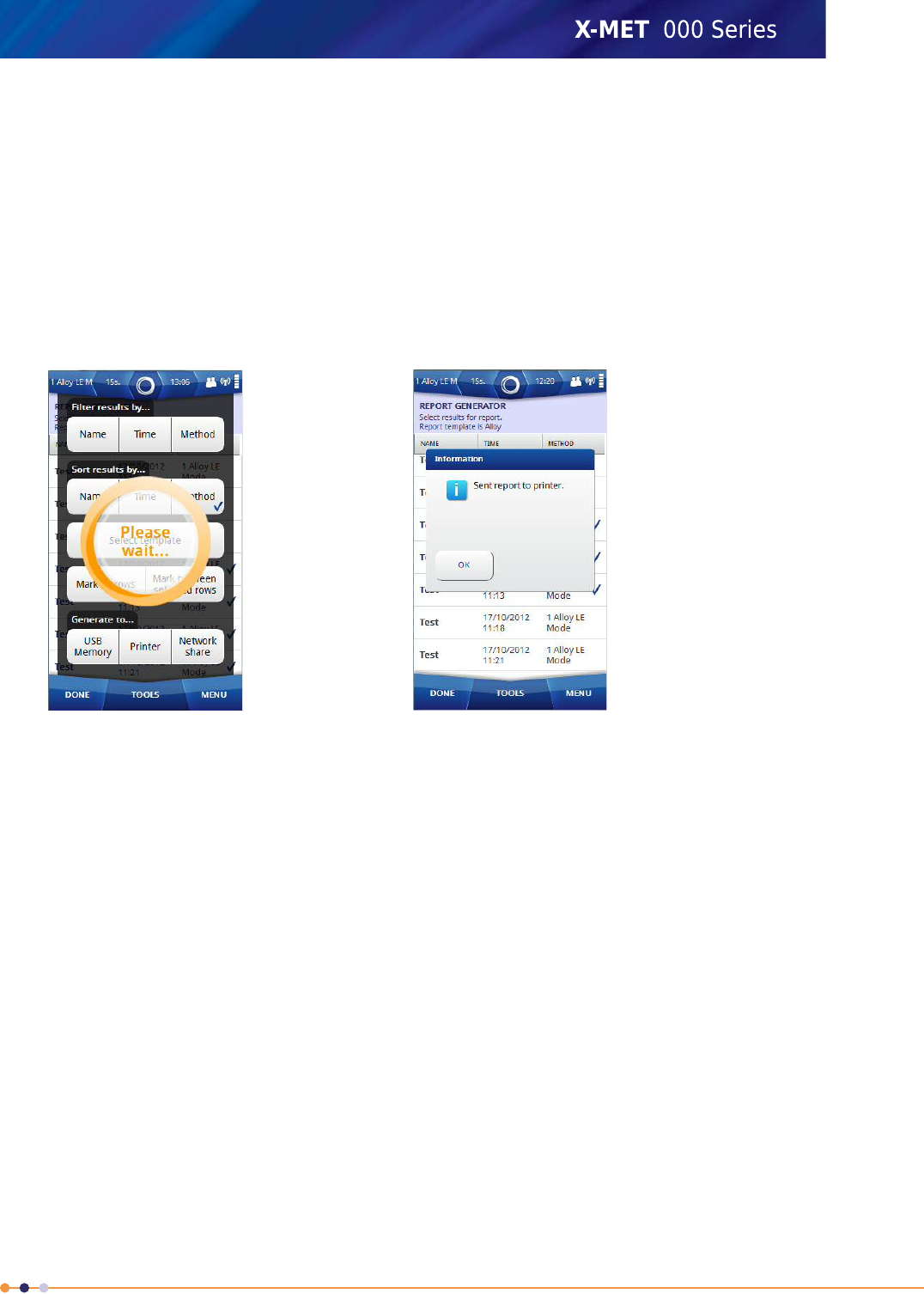
4. Tap on the applicable template and then tap Done to return to Report Generator screen.
5. Select the measurement results for the report by tapping on each result row in Report Generator
screen or tap Tools and select results using following options
•Filter by
•Sort by
•Mark All
•Mark between selected rows
6. Tap: Tools >Printer after selecting results.
Device starts generating report to the printer. Once the report is generated to the printer, an
Information dialog box appears .
7. Tap OK.
The Report Generator screen appears.
8. Tap Done twice to return to the main screen.
163
X-MET8000 Series User Manual
8
Wireless File Transfers
The X-MET8000 series can store reports directly to a network share over a Wi-Fi connection. Setup
shared folders using the following instructions.
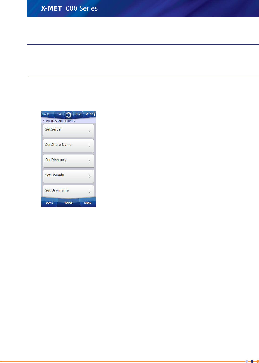
Configure Network Share Settings
Follow the steps below to configure the Network Share Settings.
1. Navigate: Menu >Settings >Instrument Configuration >Network Share .
The Network Share Settings screen appears.
2. Do all of the following:
•Set Server
Set Server is the IP address of the server hosting the network share.
•Set Share Name
Set Share name is the name of the network share.
•Set Directory
Set Directory is the directory path inside the network share.
•Set Domain
Set Domain is the domain or workgroup where the user account is created.
•Set Username
Set Username is the username of the user to access the network share.
•Set Password
Set Password is the password of the user to access the network share.
164
X-MET8000 Series User Manual
8
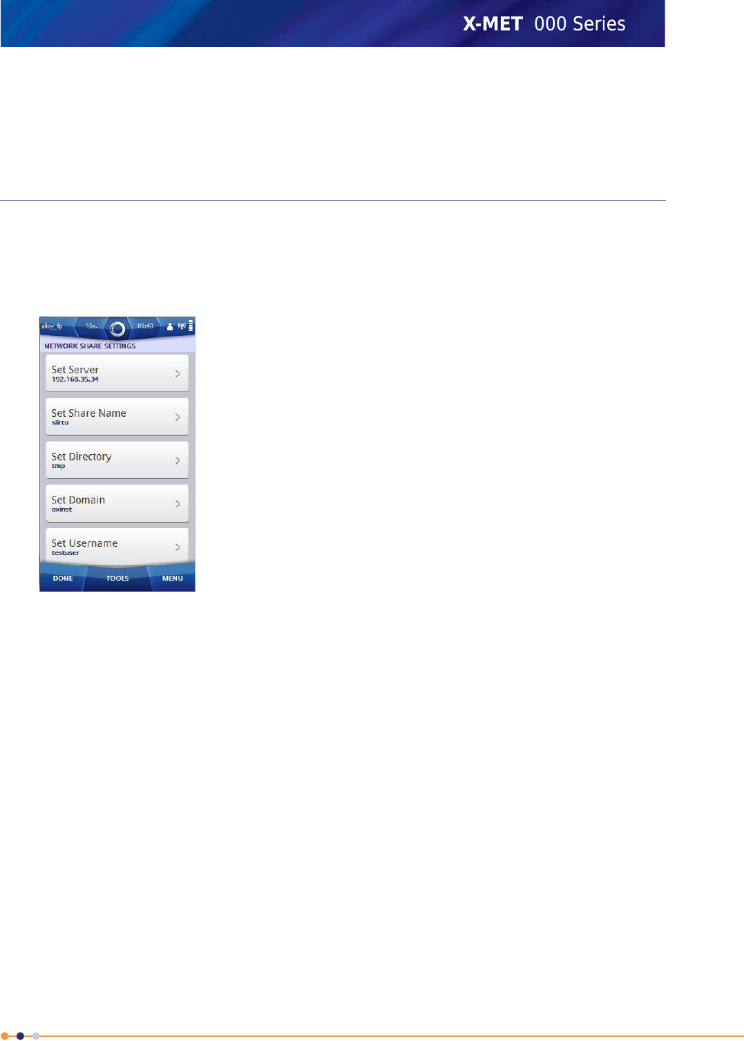
3. The sytem administrator will know the settings of the available shares in the network, and can
provide the necessary information for the Network Share Settings. Use the virtual keyboard to type
the new value, and tap Done to return to the Network Share settings.
4. Tap Done three times to return to the main screen.
Write Test File To Network
It is necessary to configure the Network Share Settings before writing a test file to the network. Follow
these steps to write a test file.
1. Navigate: Menu >Settings >Instrument Configuration >Network Share .
The Network Share Settings screen appears.
2. Tap Tools >Write Test File .
The Information dialog box appears.
3. Tap OK and then tap Done three times to return to the main screen.
165
X-MET8000 Series User Manual
8
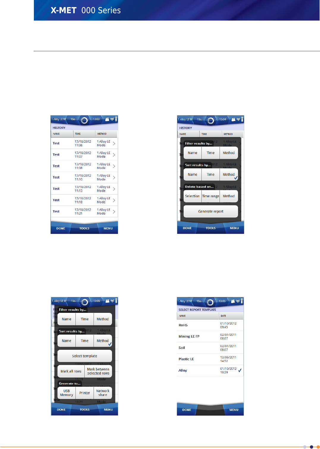
Generate Report to Network Share
The Supervisor must configure the network share in order to save reports on the selected network,
and must connect the device to the same WiFi network as the one to which the server hosting the
network share is connected. Please refer to the Supervisor manual to set this up. Follow the below
steps to generate report to Network Share.
1. Tap Menu, and then tap History.
The History screen appears.
2. Tap: Tools >Generate Report
The Report Generator screen appears.
3. Tap: Tools >Select Template
The Select Report Template screen appears with the list of the default report templates and user
defined templates which were created in the Web GUI.
166
X-MET8000 Series User Manual
8
4. Tap on applicable template and then tap Done to return to Report Generator screen.
5. Select the measurement results for the report by tapping on each result row in the Report Generator
screen or tap Tools and select the results using following options.
•Filter by
•Sort by
•Mark All
•Mark between selected rows
6. Tap: Tools >Network Share after selecting the results.
Device starts generating report to the printer. Once the report is generated to the network share
Report Generator screen appears.
7. Tap Done twice to return to the main screen.
VNC connection to the X-MET8000 series
The X-MET8000 series can be used trough VNC over a Wi-Fi connection. Setup a VNC connection using
the following instructions.
Using a VNC connection all the operations that are available locally on the X-MET8000 series are
accessible trough remote screen.
167
X-MET8000 Series User Manual
8
Configure VNC Server Settings
It is necessary to have a VNC client on computer to connect to the X-MET device's VNC server. Contact
your IT service administrator to setup a VNC client on your computer. A VNC connection can be
established by connecting a VNC client with a VNC server using either the X-MET device's Wi-Fi IP
address, or the IP address 10.0.0.1 when using a direct USB connection. Follow the steps below to
configure the VNC server settings in the device.
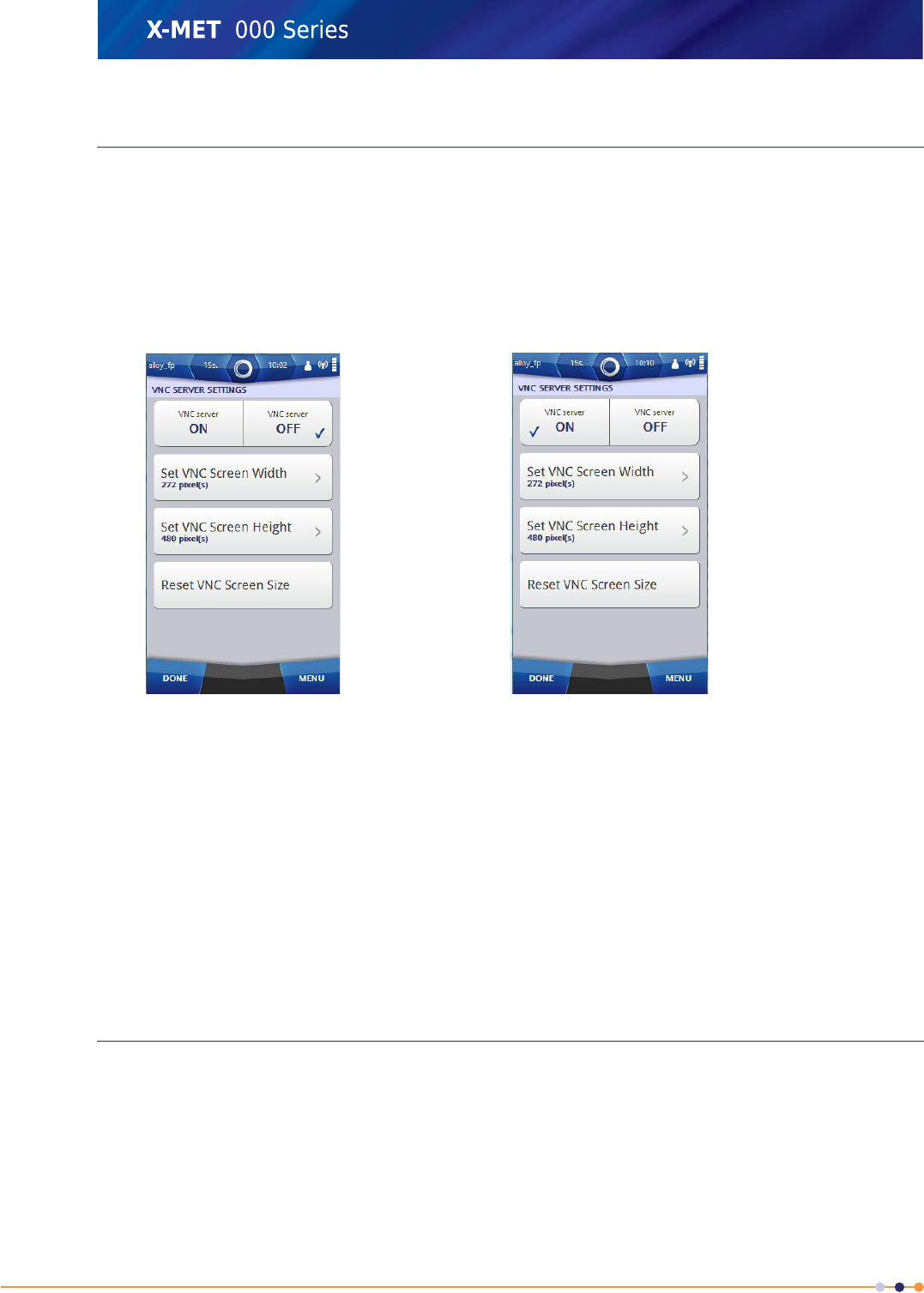
1. Navigate: Menu >Settings >Instrument Configuration >VNC Server .
The VNC Server Settings screen appears.
2. Tap VNC Server ON.
The Information dialog box appears.
3. Tap OK to return to the VNC Server Settings.
4. If necessary, do the following to change the VNC screen width and height before setting VNC
Server ON.
•Set VNC Screen Width
•Set VNC Screen Height
5. Use the virtual keyboard to type the new value, and tap Done to return to the VNC Server Settings.
6. To reset the VNC screen width and height to the default values, tap Reset VNC Screen Size.
7. Tap Done three times to return to the main screen.
Setup a VNC connection on a PC
Follow these steps to set up a VNC connection on a PC and connect to the X-MET8000 series.
It is necessary to have a VNC client on computer to connect to the X-MET8000 series device's VNC
server. Contact your IT service administrator to setup a VNC client on your computer. A VNC connection
can be established by connecting a VNC client with a VNC server using either the X-MET8000 series
device's Wi-Fi IP address, or the IP address 10.0.0.1 when using a direct USB connection. The VNC
Server must be set up on the X-MET8000 series before a connection can be established.
168
X-MET8000 Series User Manual
8
1. On the PC, Download and install a VNC client, i.e. RealVNC Viewer from http://www.realvnc.com.
Follow the instructions for the selected software to install the VNC client.
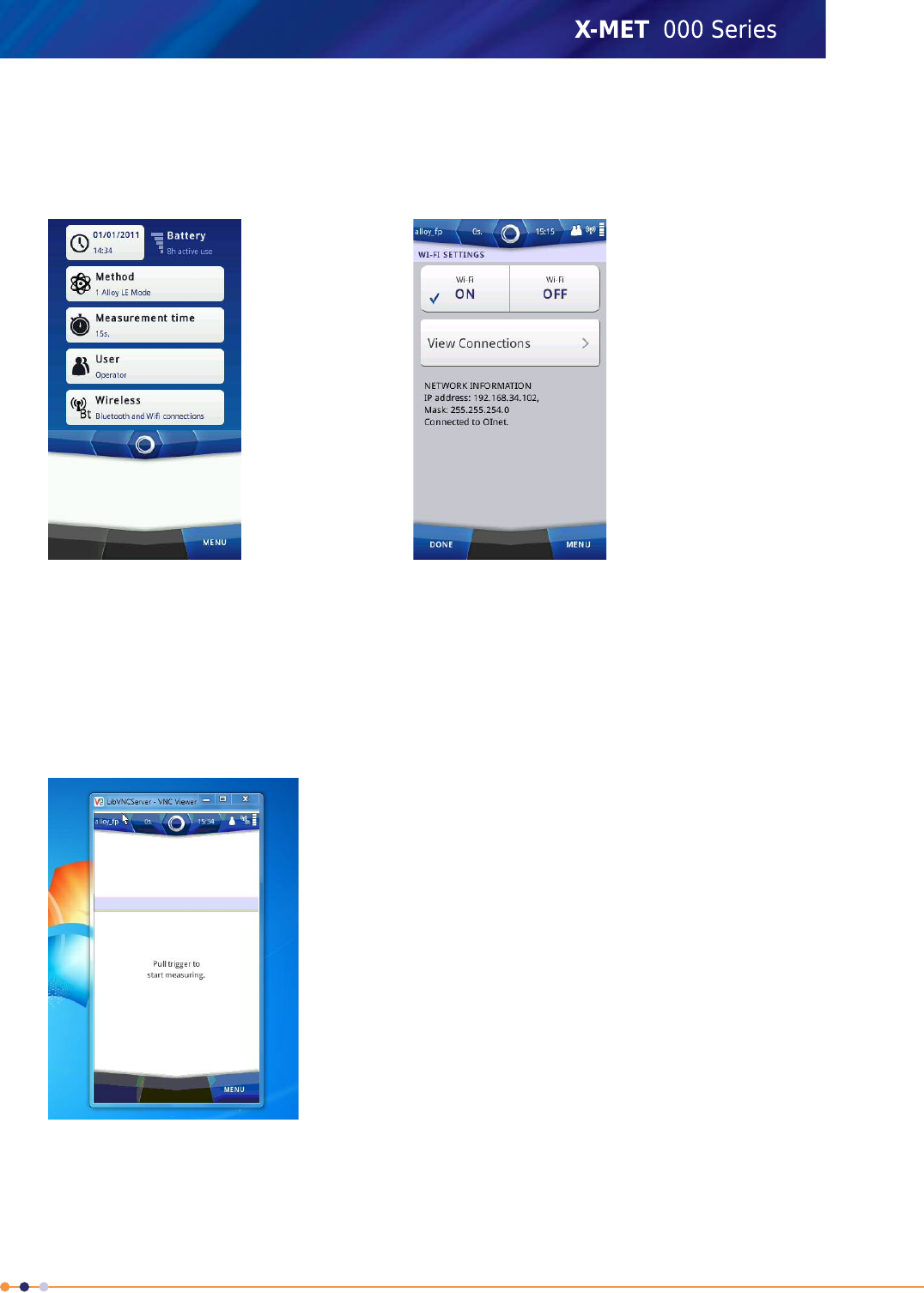
2. Start the VNC Client on the PC and enter the X-MET8000 series IP address found under Network
settings Status Bar >Wireless >Wi-Fi .
3. On the VNC client, tap Connect to open the remote connection.
If the VNC client is unable to connect to the X-MET8000 series it might be necessary to disable and
restart the Wi-Fi on the X-MET8000 series, from the Wi-Fi settings, tap OFF and then ON again to
restart the adapter.
4. If prompted for a passcode in the VNC client, leave this blank.
The X-MET8000 series screen appears on the PC. The X-MET8000 series can now be controlled
from the PC.
5. To end the VNC connection, tap Close Connection from the tools menu.
The VNC window on the PC closes.
169
X-MET8000 Series User Manual
8
Control the X-MET8000 series using an iPad
An iPad or similar tablet can be used to control the X-MET8000 series trough VNC over a Wi-Fi
connection. Setup a iPad VNC connection using the following instructions.
Setup an iPad to control the X-MET8000 series
Follow these steps to install and set up a VNC client on a iPad to connect to the X-MET8000 series.
The same basics can be applied to other tablets.
The Wi-Fi and VNC Server must be set up and started on the X-MET8000 series before a VNC connection
can be established.
1. On the iPad, purchase and install a VNC client of choice, these instructions are for Mocha VNC client
and can also be used as a guide for other VNC clients.
Follow the instructions for the selected software to install the VNC client.
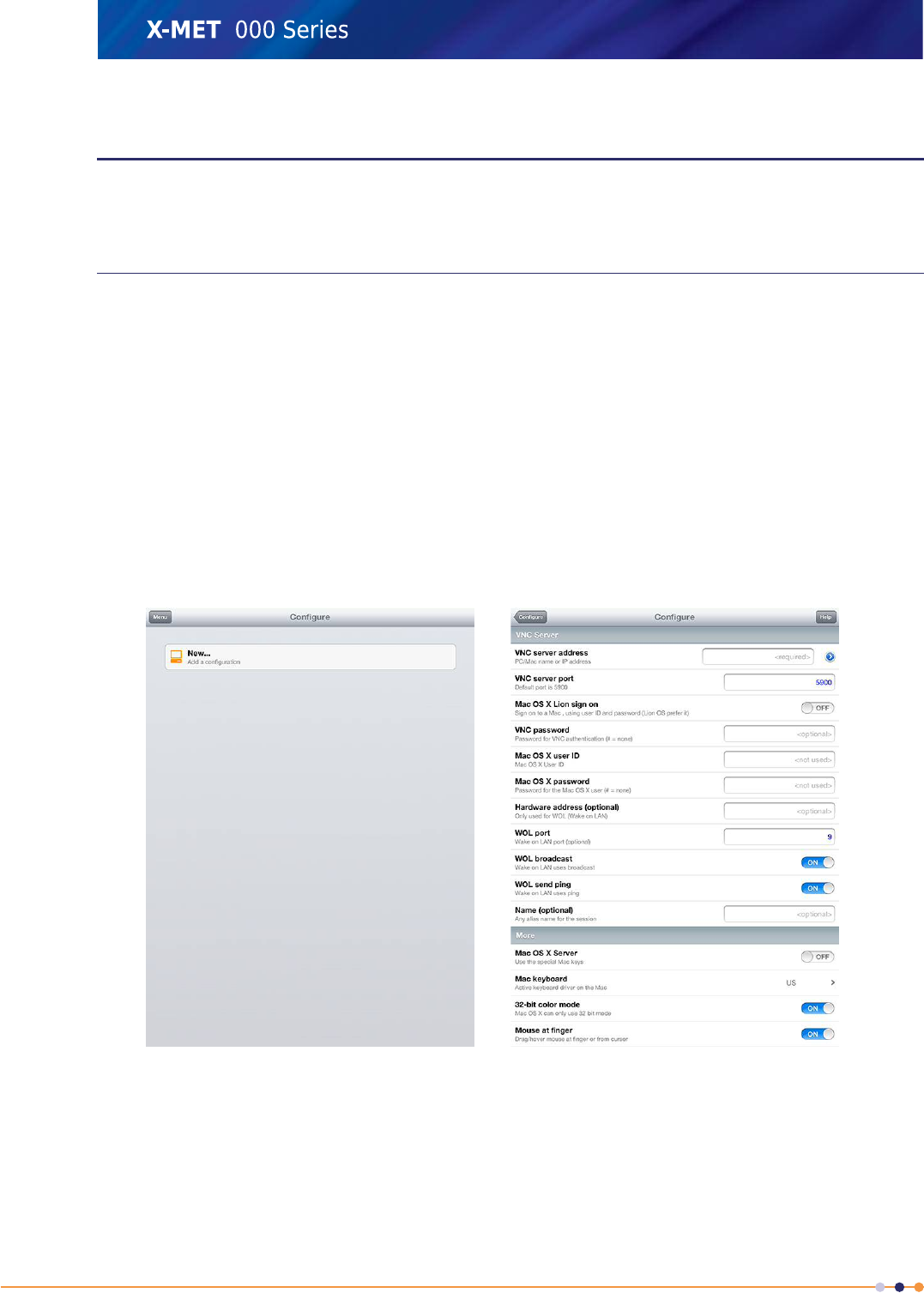
2. Start the VNC Client on the iPad. When started for the first time, add a New connection by tapping
on New.
If a connection already exists, use Menu/Add another Server to add new servers.
Once a connection is stored, use the Menu in the upper left corner to switch between Connect
and Configure.
170
X-MET8000 Series User Manual
8
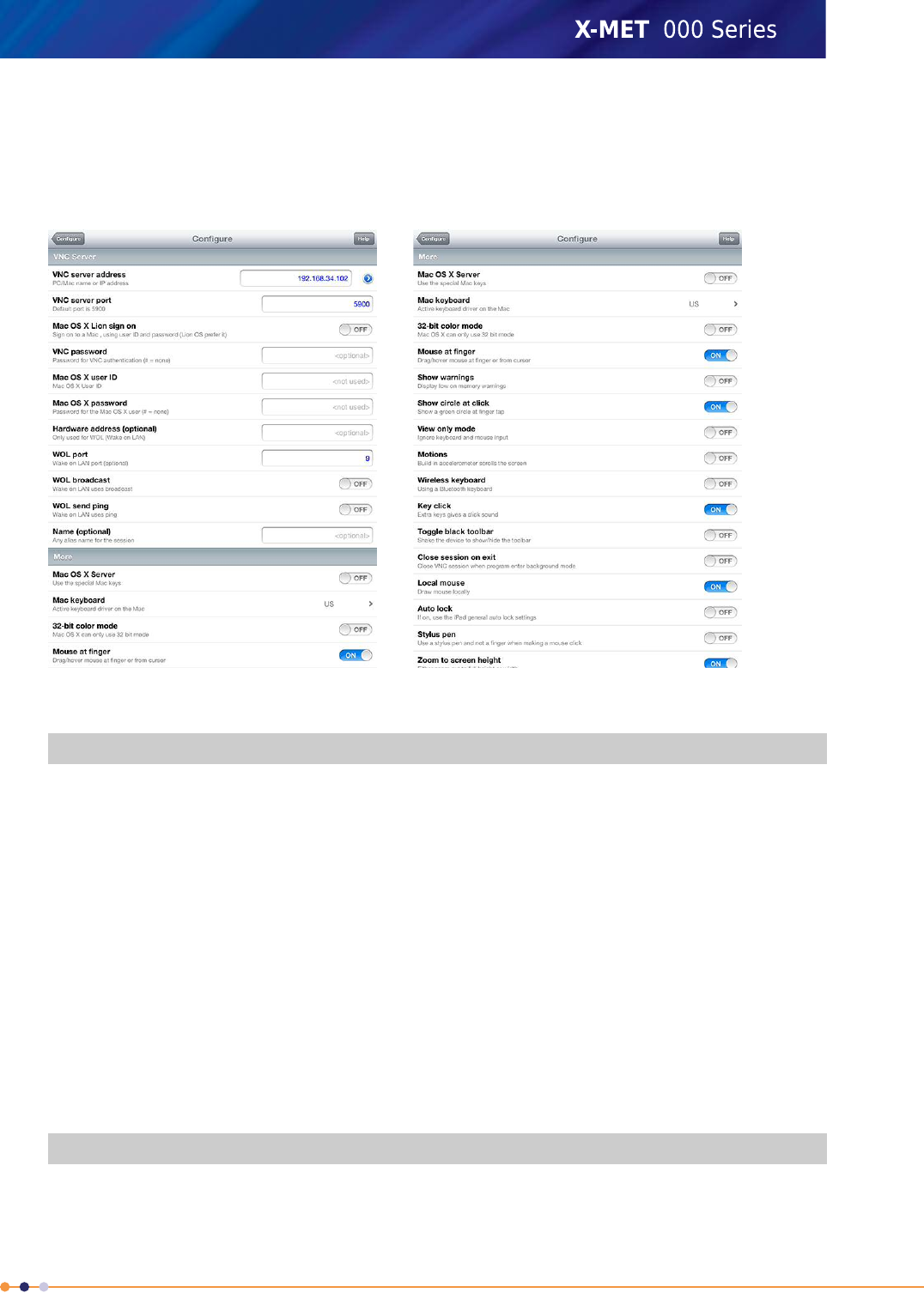
3. In the VNC client, enter the X-MET8000 series IP address found under Network settings (Navigate:
Status Bar >Wireless >Wi-Fi ) and verify that that the settings in the VNC client are according
to the following table:
Note, 32-bit color mode will not work with the X-MET8000 series, other default settings in Mocha
VNC should be adequate.
Table 4: Configuration table
ValueVNC Server
X-MET8000 series IP addressVNC server address
5900VNC server port
OFFMac OS X Lion sign on
<optional>VNC password
<not used>Mac OS X User ID
<not used>Mac OS X Password
<optional>Hardware address
(optional)
9WOL port
OFFWOL broadcast
OFFWOL send ping
<optional>Name (optional)
ValueMore
OFFMac OS X server
171
X-MET8000 Series User Manual
8

ValueMore
US or according to keyboard preferencesMac keyboard
OFF32bit color mode
ONMouse at finger
OFFShow warnings
ONShow circle at click
OFFView only mode
OFFMotions
OFFWireless keyboard
ONKey click
OFFToggle black toolbar
OFFClose session on exit
ONLocal mouse
OFFAuto lock
OFFStylus pen
ONZoom to screen height
4. Follow the steps in the next chapter to connect and control the X-MET8000 series using the iPad.
Control the X-MET8000 series using an iPad
Follow these steps to connect to the X-MET8000 series using an iPad. The same basics apply also to
other tablets.
Wi-Fi and the VNC Server must be set up and started on the X-MET8000 series and the IP address of
the X-MET8000 series must be known before a connection can be established.
172
X-MET8000 Series User Manual
8
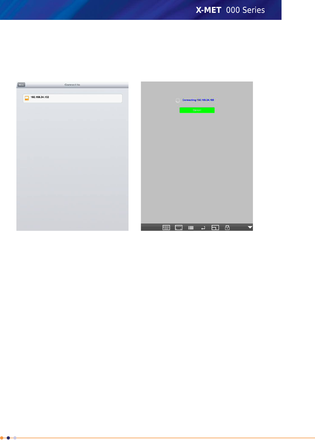
1. Tap on the connection with the IP address for the X-MET8000 series to connect to. If necessary,
tap Menu in the upper left corner to switch between Connect and Configure.
If no connection exist for the correct IP address, add a new server or modify an existing connection
to match the X-MET8000 series current IP address.
The VNC connection to the X-MET8000 series is started.
173
X-MET8000 Series User Manual
8
2. If prompted for a passcode, this can be left blank.
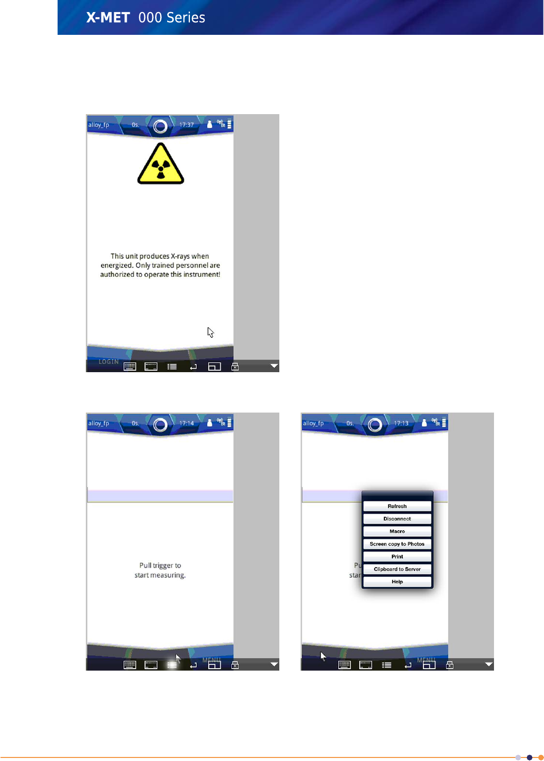
The X-MET8000 series screen appears on the iPad. Log in to the X-MET8000 series as usual, the
X-MET8000 series can now be controlled using the iPad.
3. To end the VNC connection, tap Menu Symbol at the bottom of the iPad screen.
4. Tap Disconnect to end the VNC session.
The VNC session ends.
174
X-MET8000 Series User Manual
8
Manage Backups
It is possible to back up the configuration of the X-MET8000 series. This includes calibration data and
application data. The calibration data includes the main calibration data as well as test calibration
data. Application data includes Results screen formats, report templates and Additional Information
about the sample.
The X-MET8000 series creates an internal backup and a backup on a USB memory device at the same
time. It is necessary to have a USB memory device to create a backup, with at least 10 MB of free
disk space. It is possible to restore or to delete a backup from the internal memory or from a USB
memory device.
Create A Backup
Follow these steps to back up the configuration of the X-MET8000 series.
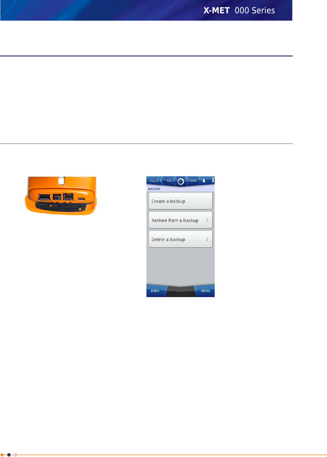
1. Open the connector cover underneath the display to access the external connections.
2. Plug a USB memory device into the USB A connector.
3. Navigate: Menu >Settings >Instrument Configuration >Configuration Backup .
The Backup Menu screen appears.
175
X-MET8000 Series User Manual
8
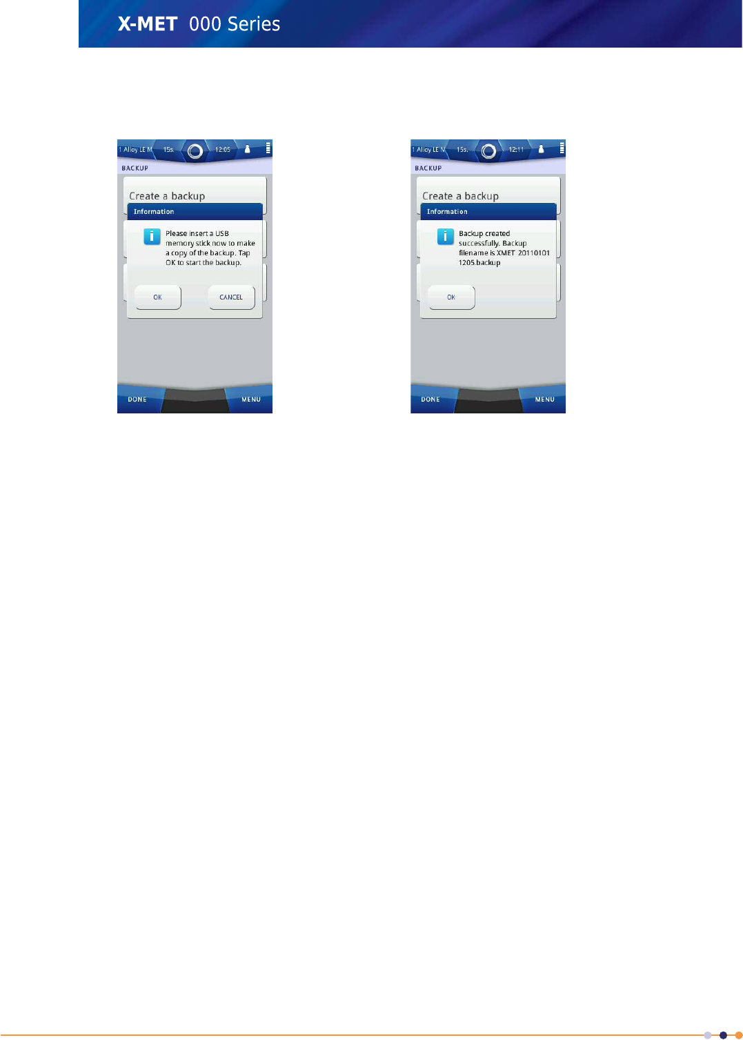
4. Tap Create A New Backup.
An Information dialog box appears.
5. Tap OK to start the backup.
The Information dialog box changes to show the progress of the backup. It can take several minutes.
When the backup is complete, the Information dialog box shows the name of the backup file.
6. Tap Done three times to return to the main screen.
7. Remove the USB memory device.
176
X-MET8000 Series User Manual
8
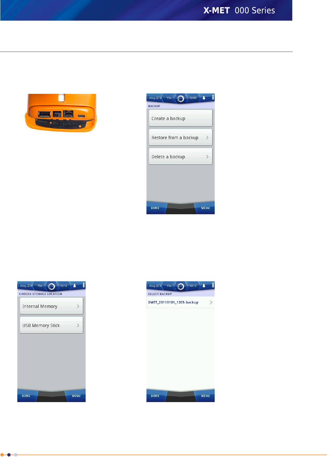
Restore A Backup
To restore a backup from the internal memory or from a USB memory device, follow these steps.
1. To restore a backup from a USB memory device, follow these two steps.
a) Open the connector cover underneath the display to access the external connections.
b) Plug a USB memory device into the USB A connector.
2. Navigate: Menu >Settings >Instrument Configuration >Configuration Backup .
The Backup Menu screen appears.
3. Tap Restore From A Backup.
The Choose Storage Location screen appears.
177
X-MET8000 Series User Manual
8
4. Do one of the following:
•Tap Internal Memory
•Tap USB Memory Stick
The Select Backup screen appears.
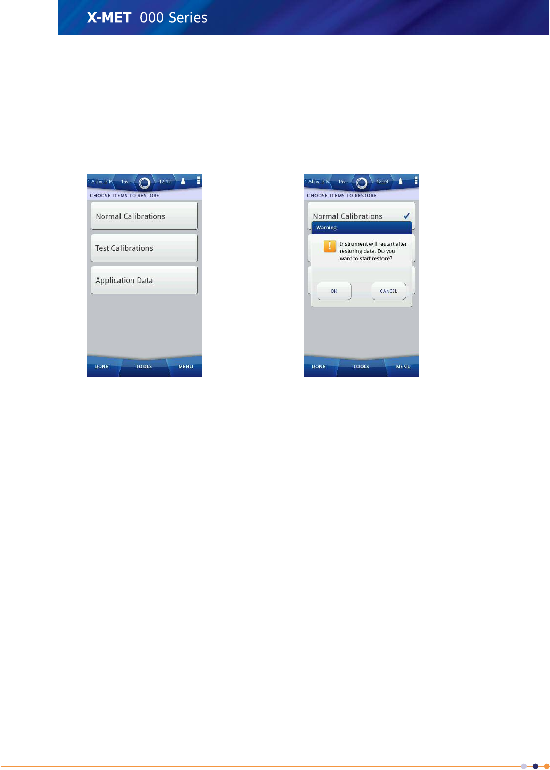
5. Tap the applicable backup.
The Choose Items To Restore screen appears.
6. Tap any or all of the following:
•Normal Calibrations
•Test Calibrations
•Application Data
A tick appears in the applicable box.
7. Make sure that all the necessary items are selected, and then tap: Tools >Restore Selected
Items .
A Warning dialog box appears.
8. Tap OK to restore the chosen backup.
When the process is complete, the Safety screen appears.
9. Remove the USB memory device.
178
X-MET8000 Series User Manual
8

Delete A Backup
To delete a backup from the internal memory or from a USB memory device, follow these steps.
1. To delete a backup from a USB memory device, follow these two steps.
a) Open the connector cover underneath the display to access the external connections.
b) Plug a USB memory device into the USB A connector.
2. Navigate: Menu >Settings >Instrument Configuration >Configuration Backup .
The Backup Menu screen appears.
3. Tap Delete A Backup.
The Choose Storage Location screen appears.
179
X-MET8000 Series User Manual
8
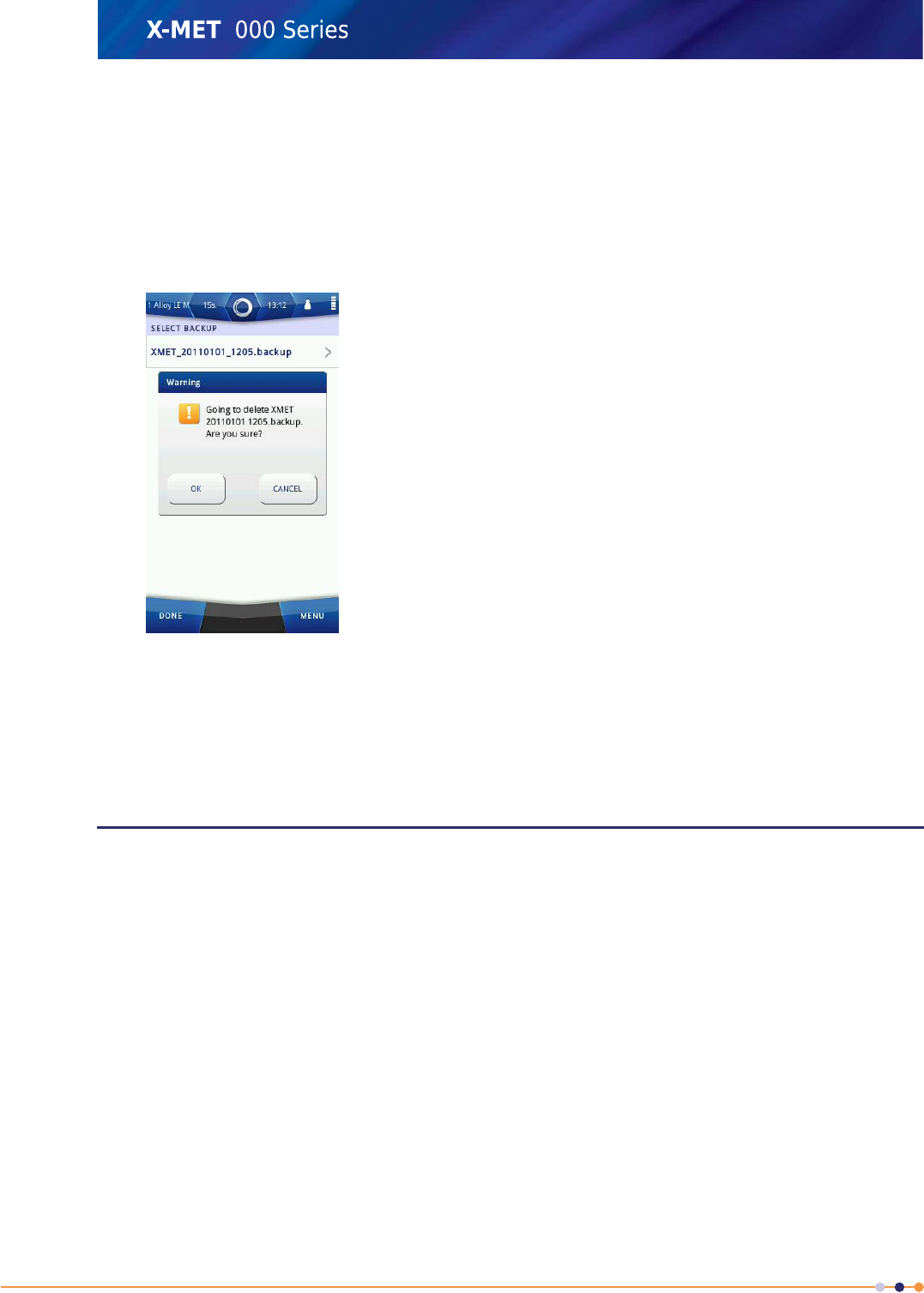
4. Do one of the following:
•Tap Internal Memory
•Tap USB Memory Stick
The Select Backup screen appears.
5. Tap the applicable backup.
A Warning dialog box appears.
6. Tap OK to delete the chosen backup.
When the process is complete, the Choose Storage Location screen appears.
7. Remove the USB memory device.
Configuration
The X-MET8000 series has two settings for power saving, Power Saving and Position Wakeup, and two
sound settings for Measurement Complete and for Warning Message.
The X-MET8000 series dims the backlight after 5 minutes if there has been no activity during that
time. After a further 5 seconds, the X-MET8000 series returns to the login screen. In addition to these
operations, if Power Saving is on, the X-MET8000 series does the following:
•Switches off the screen and backlight
•Switches off Bluetooth
•Reduces detector cooling.
The X-MET8000 series returns from Power Saving after a tap on the screen. In addition, if Position
Wakeup is on, the X-MET8000 series returns after physical movement.
180
X-MET8000 Series User Manual
8
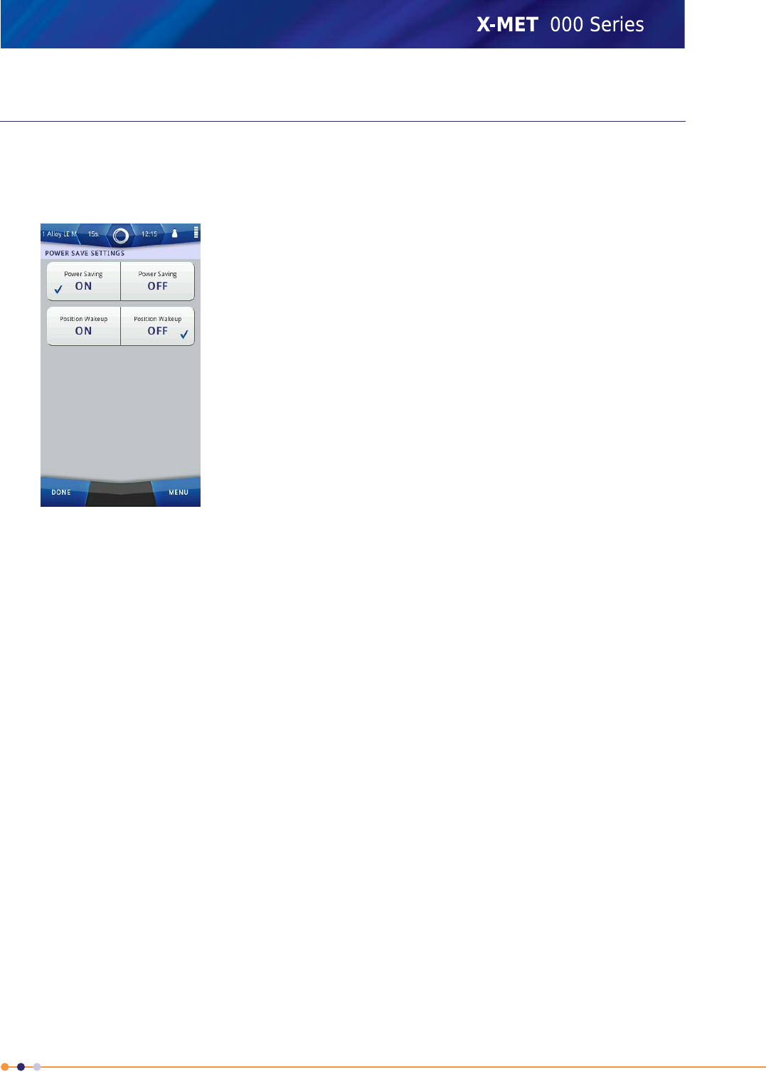
Set The Power Saving
Follow these steps to set the power saving features.
1. Navigate: Menu >Settings >Instrument Configuration >Power Saving .
The Power Save Settings screen appears.
2. For Power Saving, tap one of the following:
•ON
•OFF
3. For Position Wakeup, tap one of the following:
•ON
•OFF
4. Tap Done three times to return to the main screen.
181
X-MET8000 Series User Manual
8
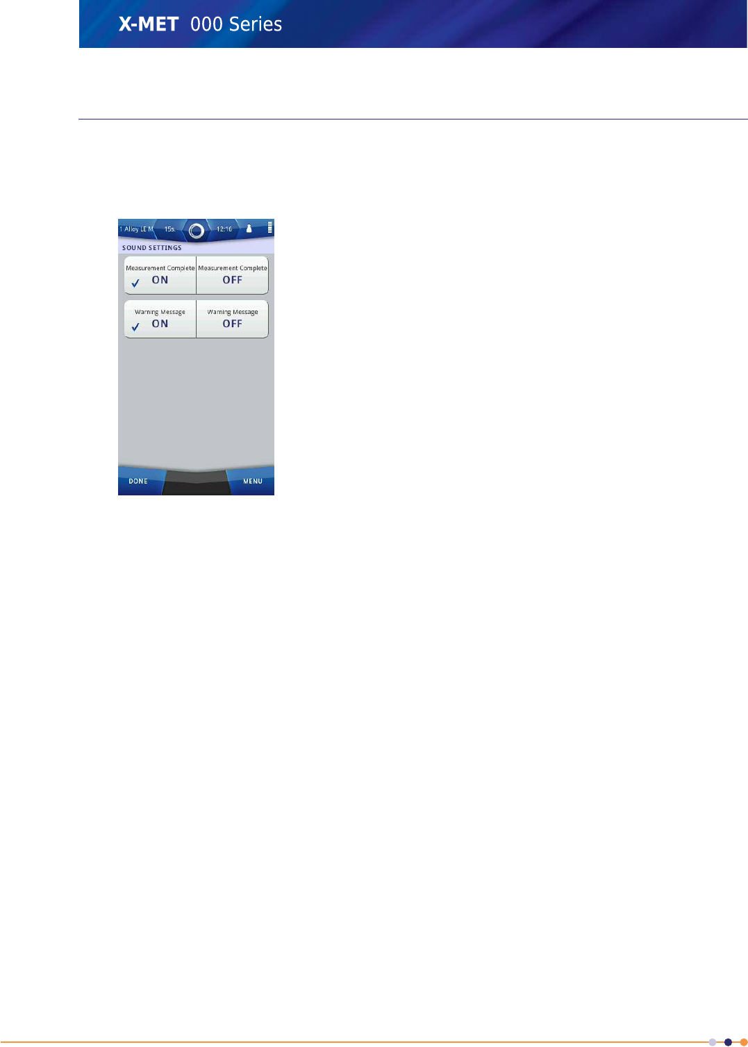
Choose Sounds
Follow these steps to set the sound features.
1. Navigate: Menu >Settings >Instrument Configuration >Sounds .
The Sound Settings screen appears.
2. For Measurement Complete, tap one of the following:
•ON
•OFF
3. For Warning Message, tap one of the following:
•ON
•OFF
4. Tap Done three times to return to the main screen.
182
X-MET8000 Series User Manual
8
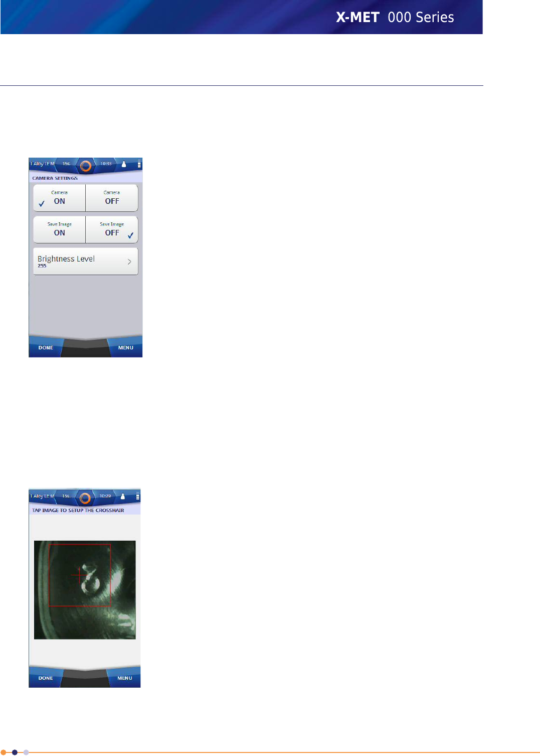
Configure Camera Settings
Follow these steps to configure the Camera settings.
1. Navigate: Menu >Settings >Instrument Configuration >Camera Settings .
The Camera Settings screen appears.
2. To enable the Camera function, tap ON. If the camera function is not required, tap OFF
If the Camera is set to OFF, Save Image, Crosshair Calibration and the Brightness Level options
disappear from the Camera Settings screen.
3. To automatically save the camera picture for each analysis, tap Save Image ON. If the camera
is primarily used for positioning the X-MET on a sample and images are not needed, tap Save Image
OFF.
4. If necessary, tap Crosshair Calibration to crop the camera image.
The Tap Image To Setup The Crosshair screen appears.
183
X-MET8000 Series User Manual
8
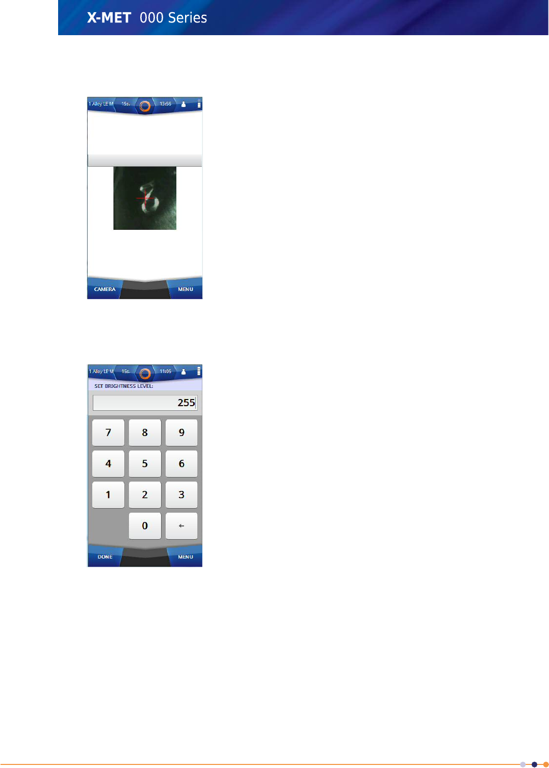
5. Tap on the image to crop. Tap Done to return to the Camera Settings.
The area inside the red square box will be displayed in the camera window and in the reports.
6. If necessary, the brightness of the camera can be increased by tapping the Brightness Level
option.
The Set Brightness Level screen appears.
7. Use the numeric keypad to type the value for the brightness level, the value must be between 0
and 255 and then tap Done to return to the Camera Settings screen.
8. Tap Done three times to return to the main screen.
184
X-MET8000 Series User Manual
8
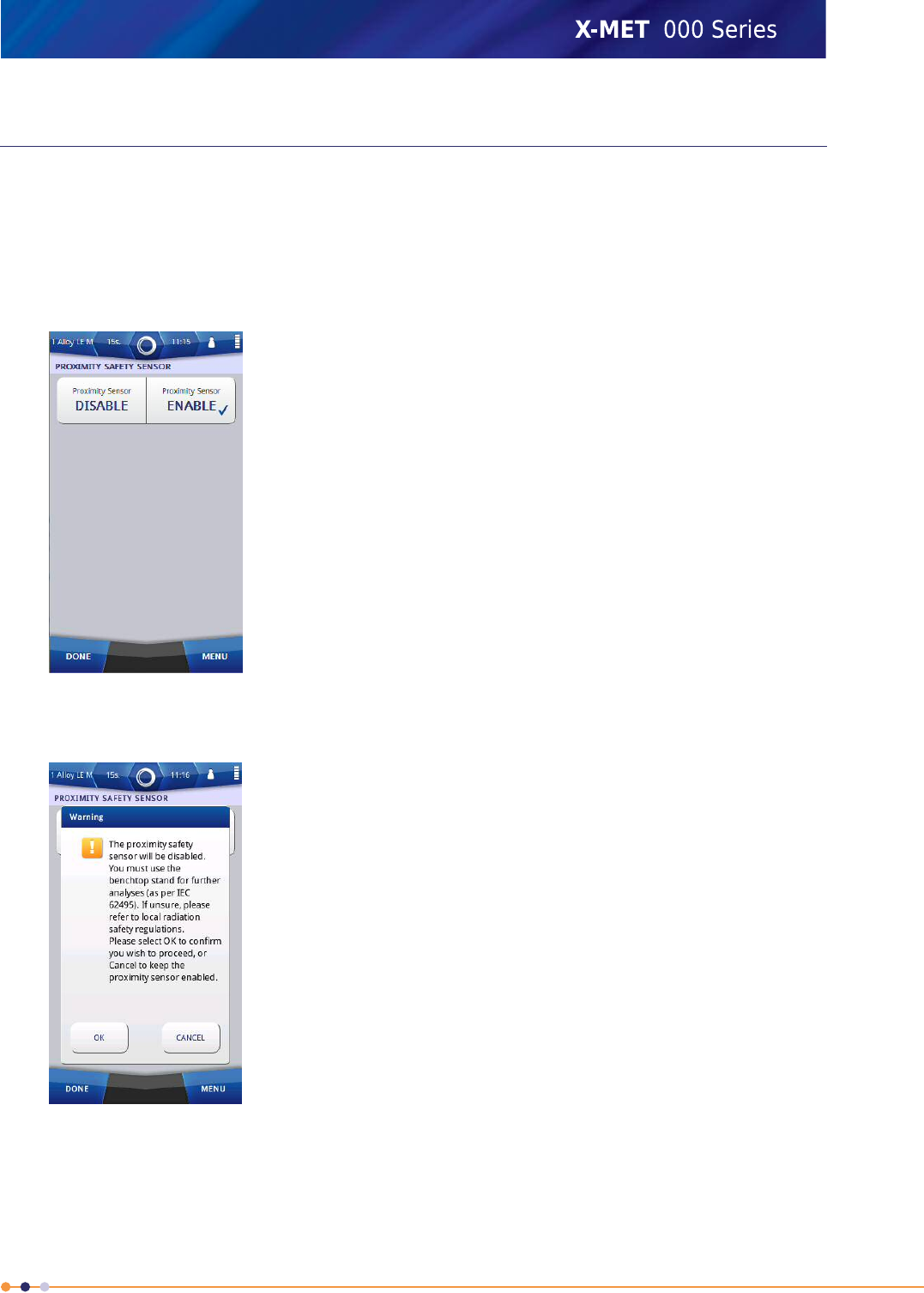
Disable the Proximity Safety Sensor
By default, the Proximity Safety Sensor is enabled in the device. The Proximity Safety Sensor
is not available in the UK and Canada regions. The Proximity Safety Sensor is not available if the
Proximity Toggel is enabled. If necessary, the Proximity Safety Sensor can be disabled by following
the steps below.
1. Navigate: Menu >Settings >Instrument Configuration >Proximity Safety Sensor .
The Proximity Safety Sensor screen appears.
2. To disable the proximity safety sensor, tap on Proximity Sensor DISABLE.
AWarning Message appears.
185
X-MET8000 Series User Manual
8
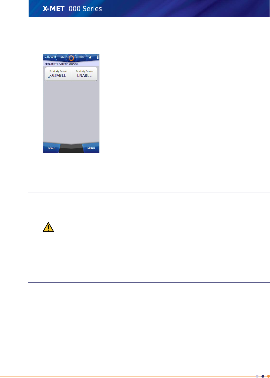
3. Tap OK.
The Proximity Safety Sensor screen appears and the Proximity indicator color in the status bar
changes to green.
4. Tap Done three times to return to the main screen.
Calibration Adjustments
Supervisors cannot add new calibrations, but they can make significant adjustments to each calibration
to optimize it for a specific application. Many of the calibration adjustments are specific to the type
of method. In addition, it is possible to do an energy calibration that adjusts all calibrations.
Caution: Any adjustments to the calibration will affect the accuracy of the X-MET8000 series.
Make sure that only trained personnel make these calibration adjustments. Failure to do so can
reduce the accuracy of the X-MET8000 series.
Please contact the local Oxford Instruments representative for assistance with all calibration
requirements. Refer to Create A Backup on page 175 before a calibration adjustment. Do several
measurements with the X-MET8000 series to make sure that it is at operational temperature before
any calibration adjustments.
Auto-Select Mode Calibration Adjustments
These adjustments are applicable to modes and also to identification methods that have an ‘ID’ suffix.
The supervisor can adjust the following:
•The recalculation method
•The limits that define both a Good Match and a Possible Match
•Maintain the reference samples used for the identification scan.
The recalculation method is used for auto-select modes as an optional third choice. The first choice
uses the identification methods to match to an applicable empirical calibration. The second choice
uses an applicable fundamental parameter calibration. If there is no match from the first or second
choice, the auto-select mode uses the optional recalculation method. Auto-select modes do not require
186
X-MET8000 Series User Manual
8
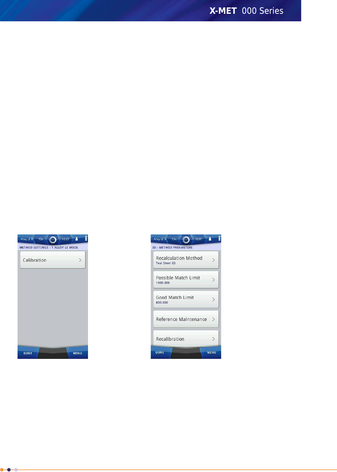
a recalculation method, and it can be undefined. A fundamental parameter method is often the best
choice for a recalculation method.
Auto-select modes use two adjustable limits to decide whether to use a particular reference sample
from an identification method. The two limits are for ‘Good Match’ and ‘Possible Match’. Reduce a
limit to make a match less likely, and increase it to make a match more likely. Make sure that the
‘Good Match’ value is less than the ‘Possible Match’ value.
Each auto-select mode and identification method has a list of the reference samples associated with
it. For modes, it is possible to associate a reference sample with another method. For example:
•Alloy LE Mode has SS304 as a reference sample that uses the Stainless LE method
•Stainless LE ID also has SS304 as a reference sample, but with no associated method.
There is a date for each reference when the measurement occurred. If there is no date, then there is
no measurement for that reference sample. If there is no date for a reference sample, then that mode
or identification method will have an incomplete calibration, and will not be available for measurements.
Do not add a reference sample without a measurement.
Choose A Recalculation Method
This procedure is applicable to modes and also to ‘ID’ methods. Follow these steps to add a recalculation
method.
1. Navigate: Menu >Method .
2. Tap Edit (pencil) next to the applicable method.
The Method Settings screen appears.
3. Tap Calibration.
The ID - Method Parameters screen appears.
187
X-MET8000 Series User Manual
8
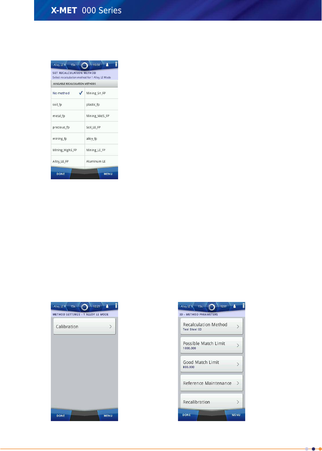
4. Tap Recalculation Method.
The Set Recalculation Method screen appears.
5. Tap an applicable method to select it.
Make sure that a tick appears in the box.
6. Tap Done to return to the ID - Method Parameters screen.
7. Tap Done three times again to return to the main screen.
Set Match Limits
This procedure is applicable to modes and also to ‘ID’ methods. Follow these steps to set the limits
for a Good Match and a Possible Match.
1. Navigate: Menu >Method .
2. Tap Edit (pencil) next to the applicable method.
The Method Settings screen appears.
188
X-MET8000 Series User Manual
8
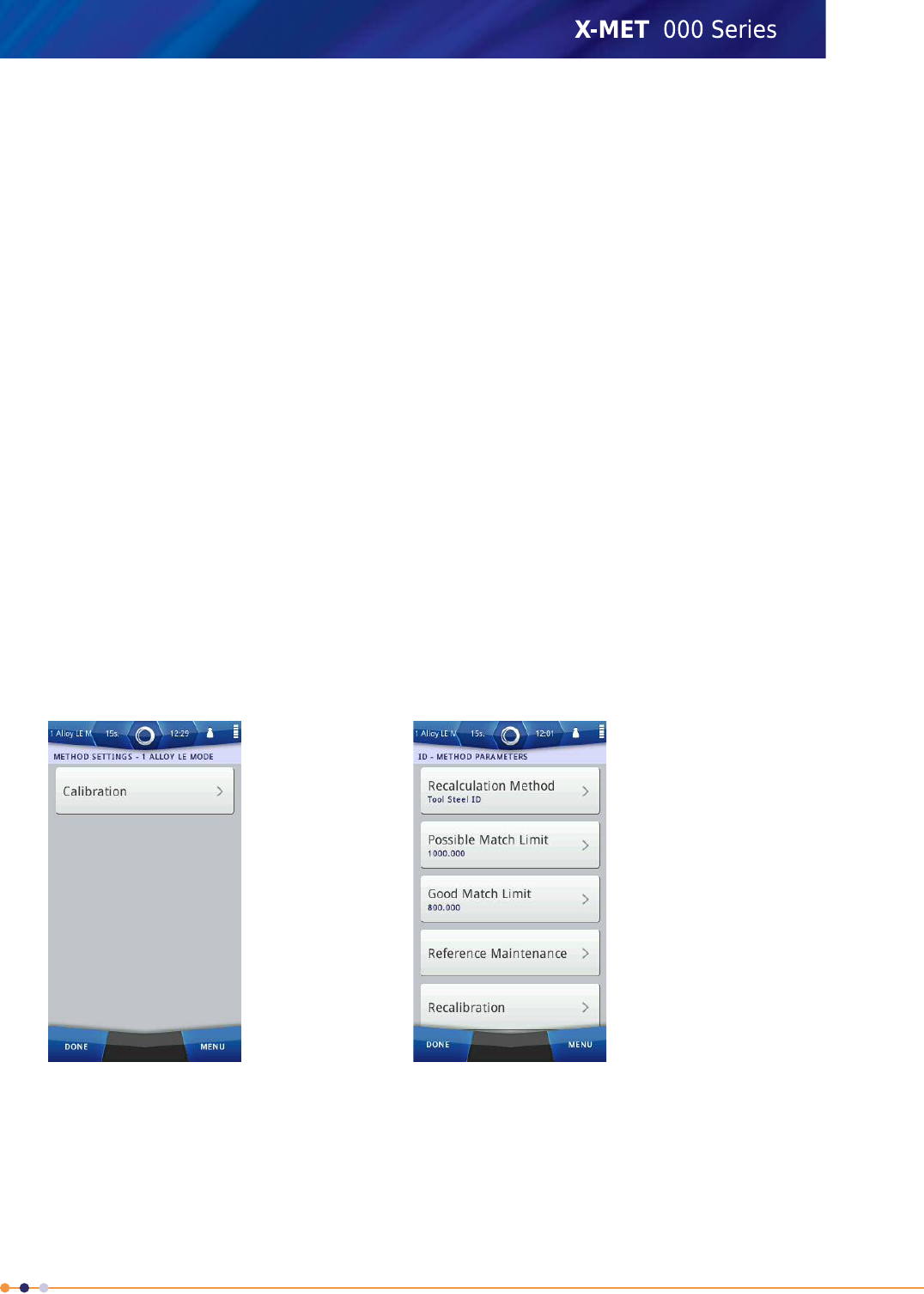
3. Tap Calibration.
The ID - Method Parameters screen appears.
4. Do one of the following:
•Tap Possible Match Limit
•Tap Good Match Limit
5. Use the numeric keypad to type the value, and then tap Done to return to the ID - Method
Parameters screen.
Repeat these steps for the other limit, if required.
6. Tap Done to return to the Method Settings screen.
7. Tap Done twice again to return to the main screen.
Add A Reference Sample
This procedure is applicable to modes and also to ‘ID’ methods. Follow these steps to add a reference
sample.
1. Do one of the following:
•Navigate: Menu >Time
•Navigate: Status Bar >Measurement Time
Make sure that the Measurement Time Settings are set correctly.
2. Navigate: Menu >Method .
3. Tap Edit (pencil) next to the applicable method.
The Method Settings screen appears.
4. Tap Calibration.
The ID - Method Parameters screen appears.
189
X-MET8000 Series User Manual
8
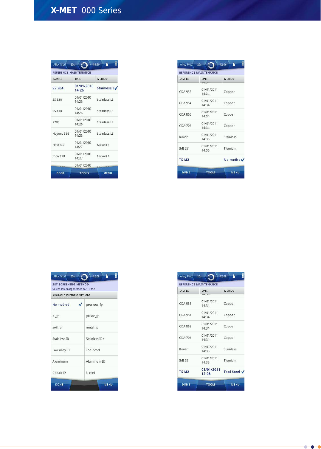
5. Tap Reference Maintenance.
The Reference Maintenance screen appears.
6. Tap: Tools >Add New .
7. Use the virtual keyboard to type a name for the new reference sample, and then tap Done to
return to the Reference Maintenance screen.
The new reference sample will be at the end of the list, and will be selected.
8. Take a measurement of the new reference sample.
The Reference Maintenance screen shows the date for the reference sample measurement.
9. For a mode, tap: Tools >Set Screening Method .
The Set Screening Method screen appears.
10. Tap an applicable method to select it.
Make sure that a tick appears in the box.
190
X-MET8000 Series User Manual
8
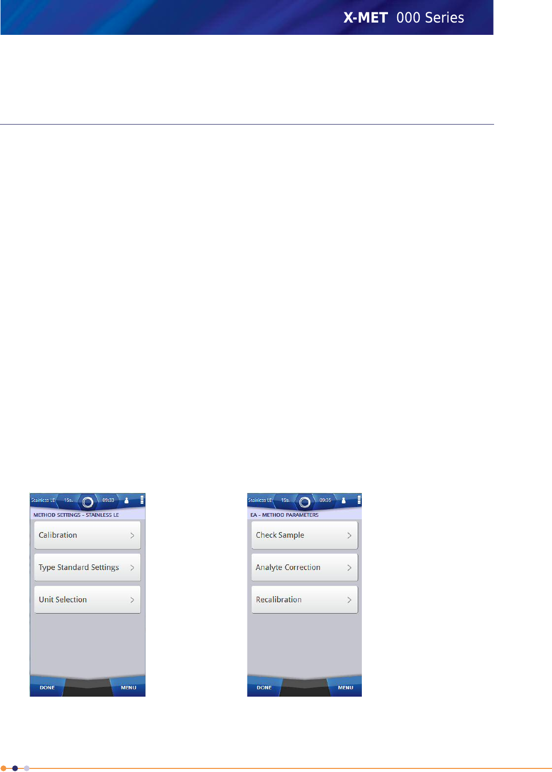
11. Tap Done to return to the Reference Maintenance screen.
12. Tap Done four times again to return to the main screen.
Empirical Calibration Adjustments
The supervisor can adjust the following:
•Measure a check sample
•Add an analyte correction
•Add a type standard setting
Check samples allow the adjustment of a calibration by the measurement of a specific sample. It is
necessary for a calibrator to include a check sample with the calibration, and typically it is only
applicable for specific applications.
Analyte correction applies an offset value to one or more specific elements within the matrix of a
calibration. It is necessary to take an accurate measurement of a sample. Analyte correction can
adjust the measurement results to be the same as the sample.
Refer to Fundamental Parameter Calibration Adjustments on page 194 for a description of type standard
settings.
Measure A Check Sample
This procedure is applicable to empirical methods. Follow these steps to measure a check sample.
1. Do one of the following:
•Navigate: Menu >Time
•Navigate: Status Bar >Measurement Time
Make sure that the Measurement Time Settings are set correctly.
2. Navigate: Menu >Method .
3. Tap Edit (pencil) next to the applicable method.
The Method Settings screen appears.
191
X-MET8000 Series User Manual
8
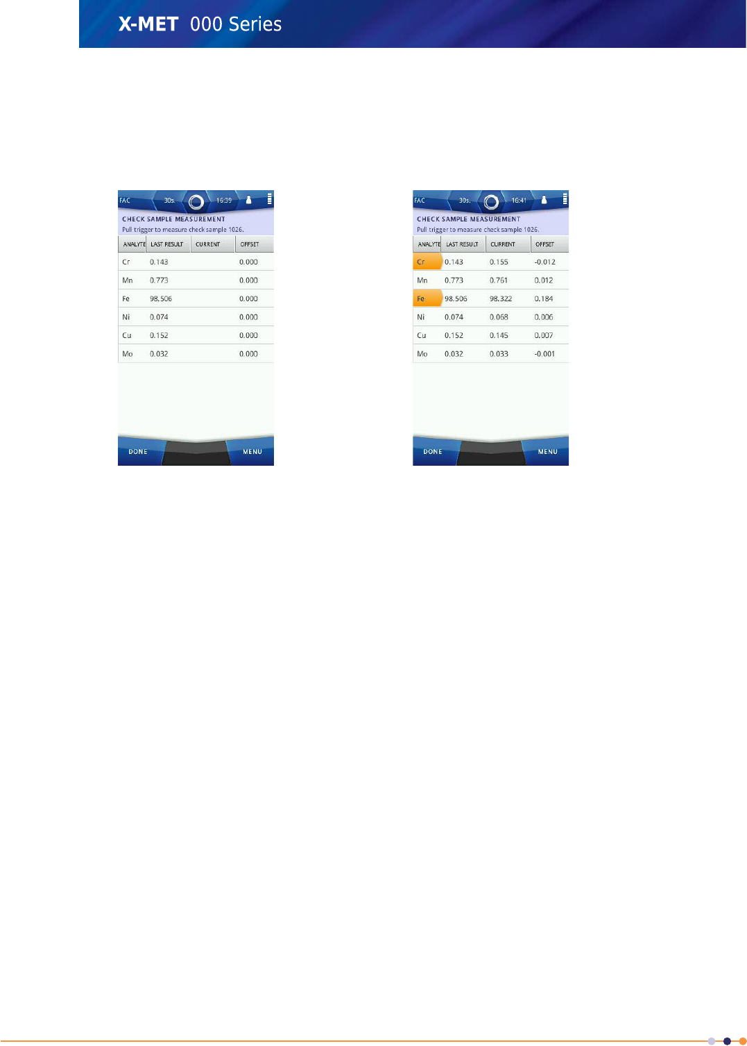
4. Tap Calibration.
The EA - Method Parameters screen appears.
5. Tap Check Sample.
The Check Sample Measurement screen appears.
6. Take a measurement of the check sample.
The Check Sample Measurement screen shows the new check sample measurement.
The Offset column shows the difference to the current check sample measurement.
7. Do one of the following:
•Tap Done to accept the new check sample measurement.
•Tap Menu >Home to reject the new check sample measurement.
8. If necessary, tap Done four times again to return to the main screen.
Add Analyte Correction
This procedure is applicable to empirical methods. Follow these steps to add analyte correction.
1. Navigate: Menu >Method .
192
X-MET8000 Series User Manual
8
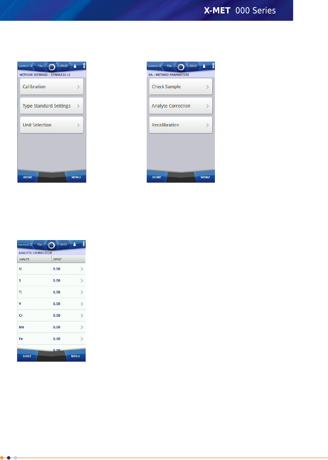
2. Tap Edit (pencil) next to the applicable method.
The Method Settings screen appears.
3. Tap Calibration.
The EA - Method Parameters screen appears.
4. Tap Analyte Correction.
The Analyte Correction screen appears.
5. Tap an applicable analyte.
6. Use the numeric keypad to type the analyte correction value, and then tap Done to return to the
Analyte Correction screen.
7. Tap Done to return to the EA - Method Parameters screen.
8. Tap Done three times again to return to the main screen.
193
X-MET8000 Series User Manual
8
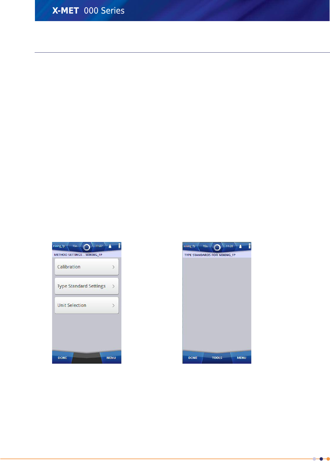
Fundamental Parameter Calibration Adjustments
The supervisor can adjust the following:
•Add a type standard setting
•Change the display units between a percentage and parts per million.
Type standards are useful for measurements within a tight matrix and narrow concentration range.
It is necessary to take an accurate measurement of a sample with known concentrations of elements.
After the measurement, it is possible to define the concentrations of each element, as applicable, to
make corrections for that type standard. Type standards are available for all empirical and fundamental
parameter calibrations.
Add A Type Standard
This procedure is applicable to empirical and fundamental parameter methods. Follow these steps to
add a type standard.
1. Do one of the following:
•Navigate: Menu >Time
•Navigate: Status Bar >Measurement Time
Make sure that the Measurement Time Settings are set correctly.
2. Navigate: Menu >Method .
3. Tap Edit (pencil) next to the applicable method.
The Method Settings screen appears.
4. Tap Type Standard Settings.
The Type Standards screen appears.
5. Tap: Tools >Add Type Standard .
194
X-MET8000 Series User Manual
8
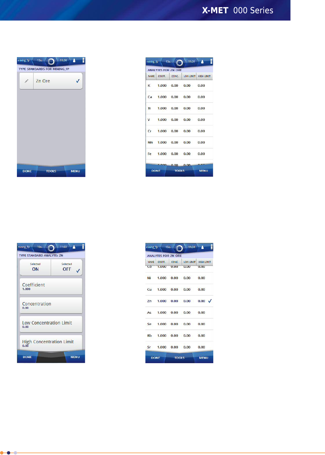
6. Use the virtual keyboard to type a name for the new type standard, and then tap Done to return
to the Type Standards screen.
7. Tap Edit (pencil) next to the new type standard.
The Analytes screen appears.
8. Take a measurement of the sample for the type standard.
9. To apply a correction, tap the applicable analyte.
The Type Standard Analytes screen appears.
10. Tap the ON tick box.
11. Do one of the following:
•Tap Coefficient
•Tap Concentration
•Tap Low Concentration Limit
•Tap High Concentration Limit
195
X-MET8000 Series User Manual
8
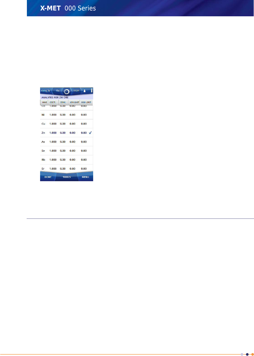
12. Use the numeric keypad to type the value, and then tap Done to return to the Type Standard
Analytes screen.
Repeat these steps for other analyte settings, if required.
13. Tap Done to return to the Analytes screen.
Repeat these steps for other analytes, if required.
14. Tap: Tools >Calculate .
The Analytes screen shows the calculated coefficients.
15. Tap Done to return to the Type Standards screen.
16. Tap Done three times again to return to the main screen.
About The Energy Calibration
Energy calibration is a service operation, and is not necessary if the X-MET8000 series operates
correctly. An energy calibration is applicable if successive measurements of the Alloy CRM sample
over a period of time show a degradation in results. It takes about 110 s, and it is possible to review
the new values after the measurement and accept them, or not.
Energy Calibration
Follow these steps to do an energy calibration. Use the Alloy CRM sample for the measurement. It is
not necessary to set a measurement time, or any other parameters. The measurement takes about
110 s.
1. Do several measurements with the X-MET8000 series to make sure that it is at operational
temperature.
196
X-MET8000 Series User Manual
8
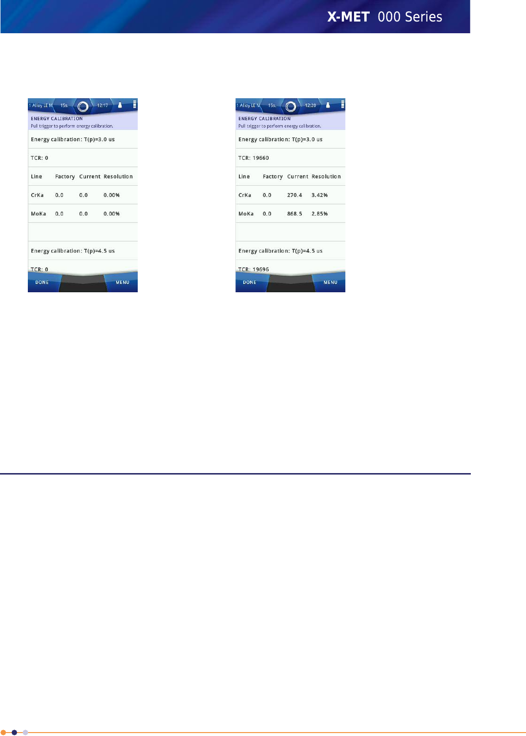
2. Navigate: Menu >Settings >Instrument Configuration >Energy Calibration .
The Energy Calibration screen appears.
3. Pull and hold the trigger firmly.
The Energy Calibration screen shows the new and old values.
A Measuring dialog box appears.
4. Do one of the following:
•Tap Done to accept the new energy calibration.
•Tap Menu >Home to reject the new energy calibration.
5. If necessary, tap Done three times again to return to the main screen.
Operation With A PC
It is possible to operate the X-MET8000 series with a PC to do the following:
•Create a report for a series of results.
•Do a test measurement.
•Access the X-MET8000 Series User Manual .
Both supervisors and operators can operate the X-MET8000 series with a PC. Each uses their own
login code. There is not a separate login code for PC operation.
Operations with the PC use an Internet browser. The standard URL to connect to the X-MET8000 series
is http://10.0.0.1/. Please contact the local Oxford Instruments representative if it is necessary to
change the URL.
197
X-MET8000 Series User Manual
8
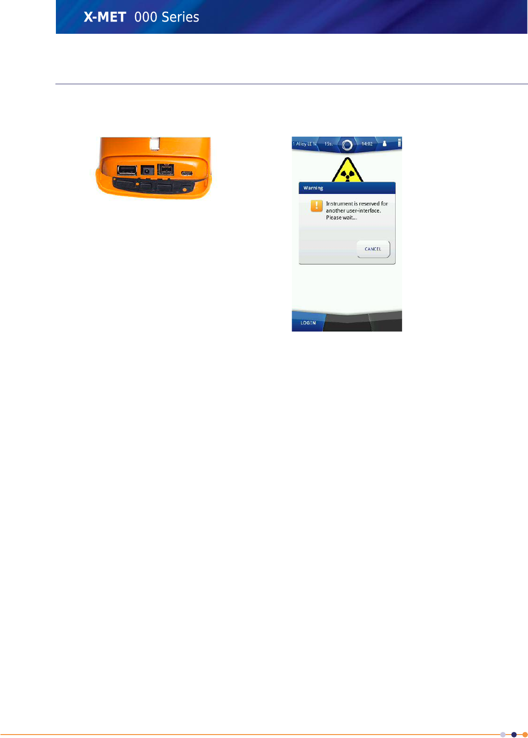
Connect To A PC And Login
Follow these steps to connect the X-MET8000 series to a PC and then login.
1. Open the connector cover underneath the display to access the external connections.
2. Use the USB cable to connect the X-MET8000 series to a PC.
•Connect the smaller USB Mini-AB connector to the X-MET8000 series.
•Connect the larger USB A connector to the PC.
Make sure that the connections are correct.
198
X-MET8000 Series User Manual
8
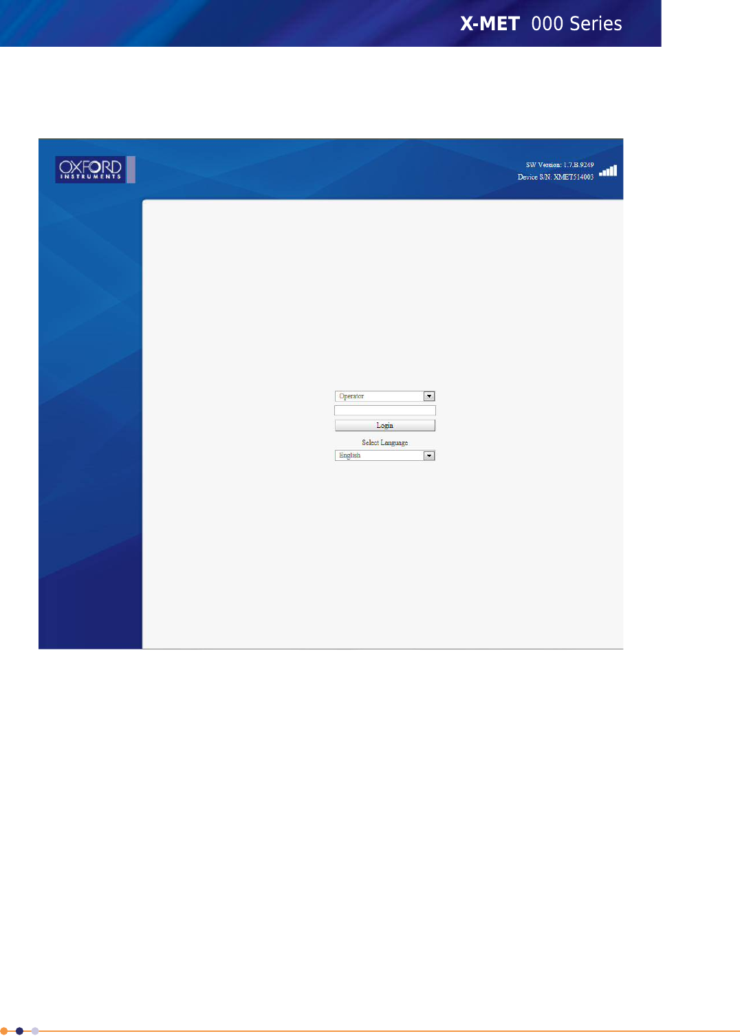
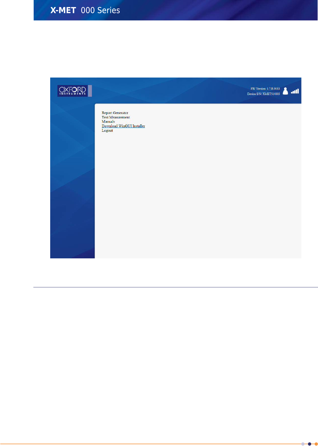
4. Select the language from drop down list and Choose the correct user from the User drop down
list, type the login code into the text box, and click Login.
The PC main screen appears.
The X-MET8000 series shows the Safety screen with a Warning dialog box.
About The Report Generator
The X-MET8000 series has a comprehensive report generator. It is possible to create templates to use
for different reports. The supervisor can create templates for an operator to use. The report generator
creates a PDF file or a CSV file. A CSV file is applicable for a spreadsheet and not available in operator
level.
The template can include company information with the logo, a report header, the date and page
number, and the X-MET8000 series serial number, as applicable. To create a report, it is necessary to
have a report template. The logo file must be less than 1024kB and one of the formats: .jpg, .png or
.bmp.
The report can include one or more results. Each result can include the operator's name, the grade
and element concentration and standard deviation. It is also possible to include the spectra for the
result, and it is possible to save the spectra with the report.
Once a supervisor creates a template, it is possible to download it to the PC, and then upload it to
other X-MET8000 series.
200
X-MET8000 Series User Manual
8