Oxford Instruments W2CBW003 802.11 b/g + Bluetooth Module User Manual part 2
Oxford Instruments 802.11 b/g + Bluetooth Module part 2
UserManual.wiki
>
Oxford Instruments
>
W2CBW003 User Manual
>
User manual part 2
Contents
1.
User manual part 1
2.
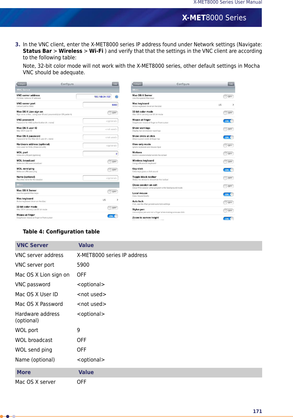
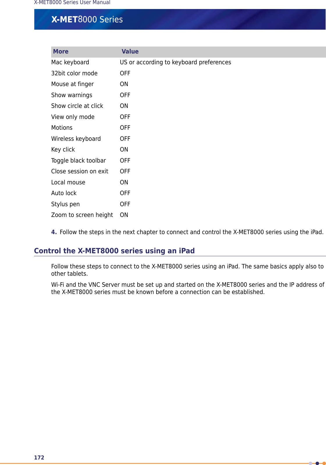
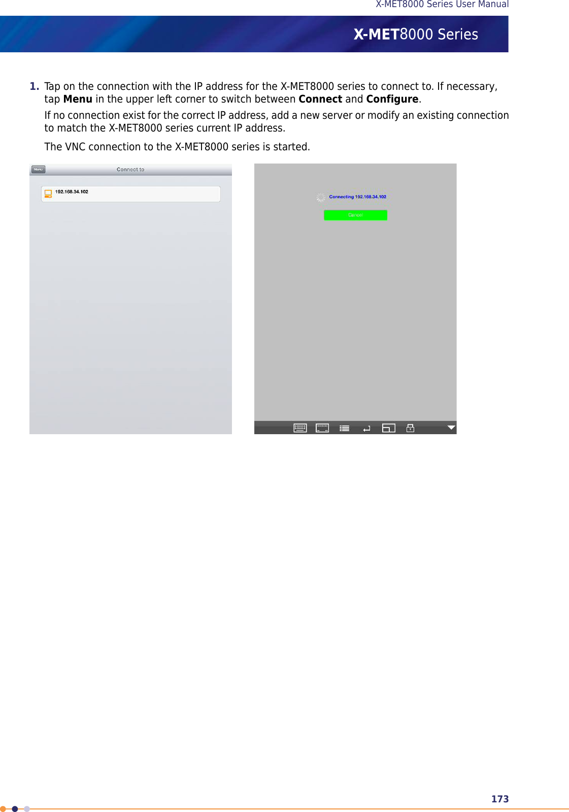
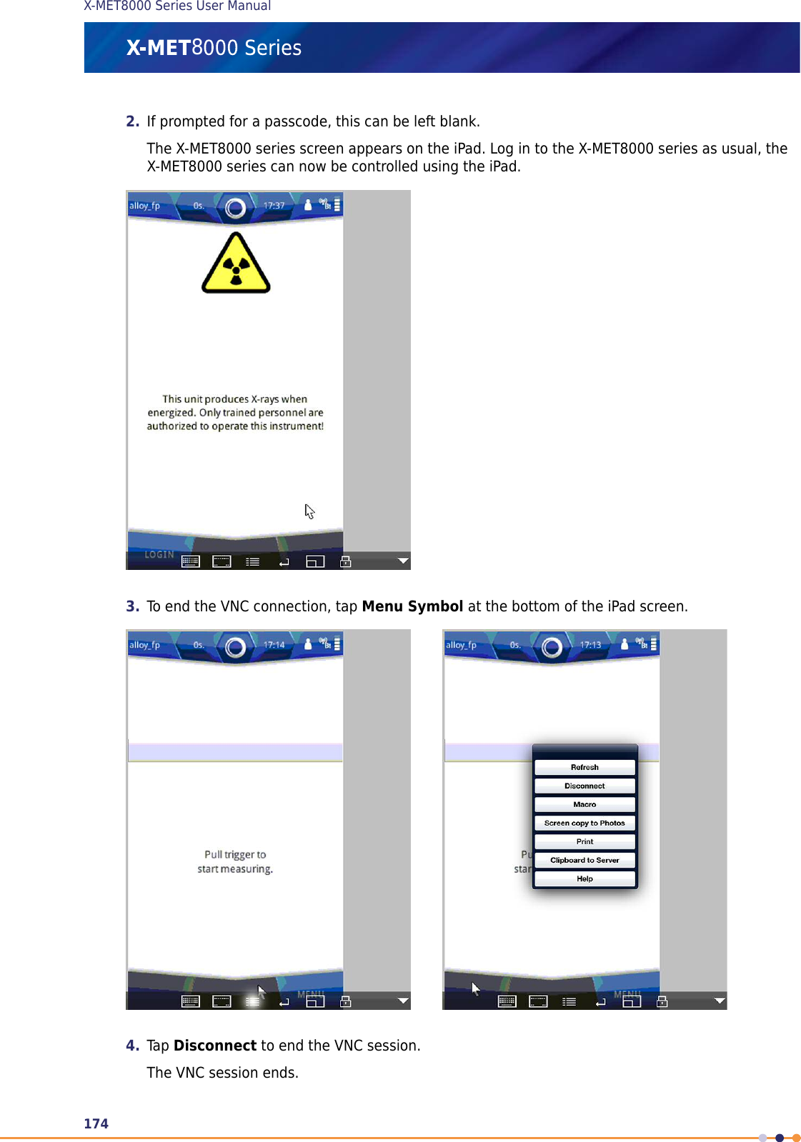
User manual part 2
3.
User manual part 3
4.
User Manual part 1
5.
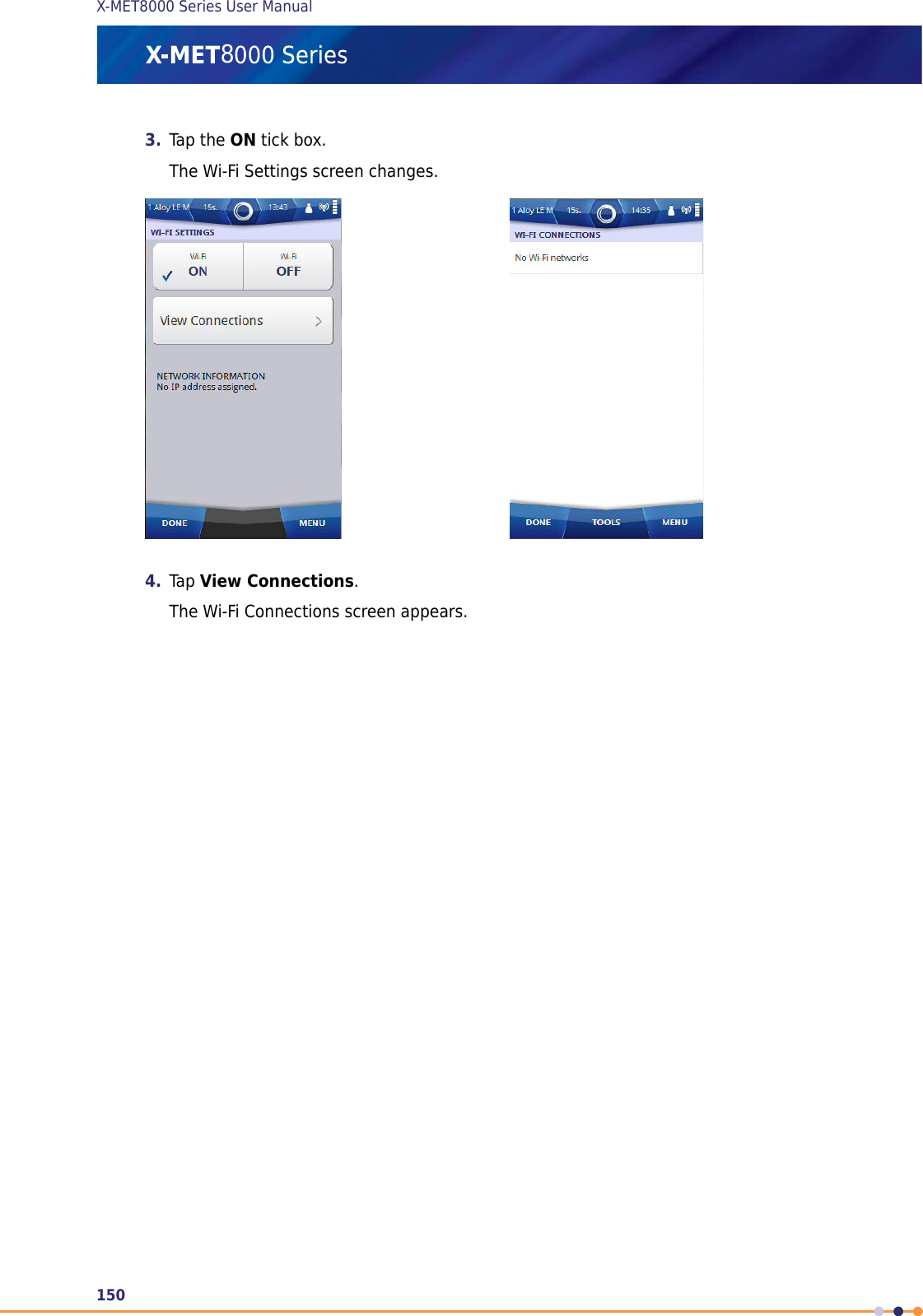
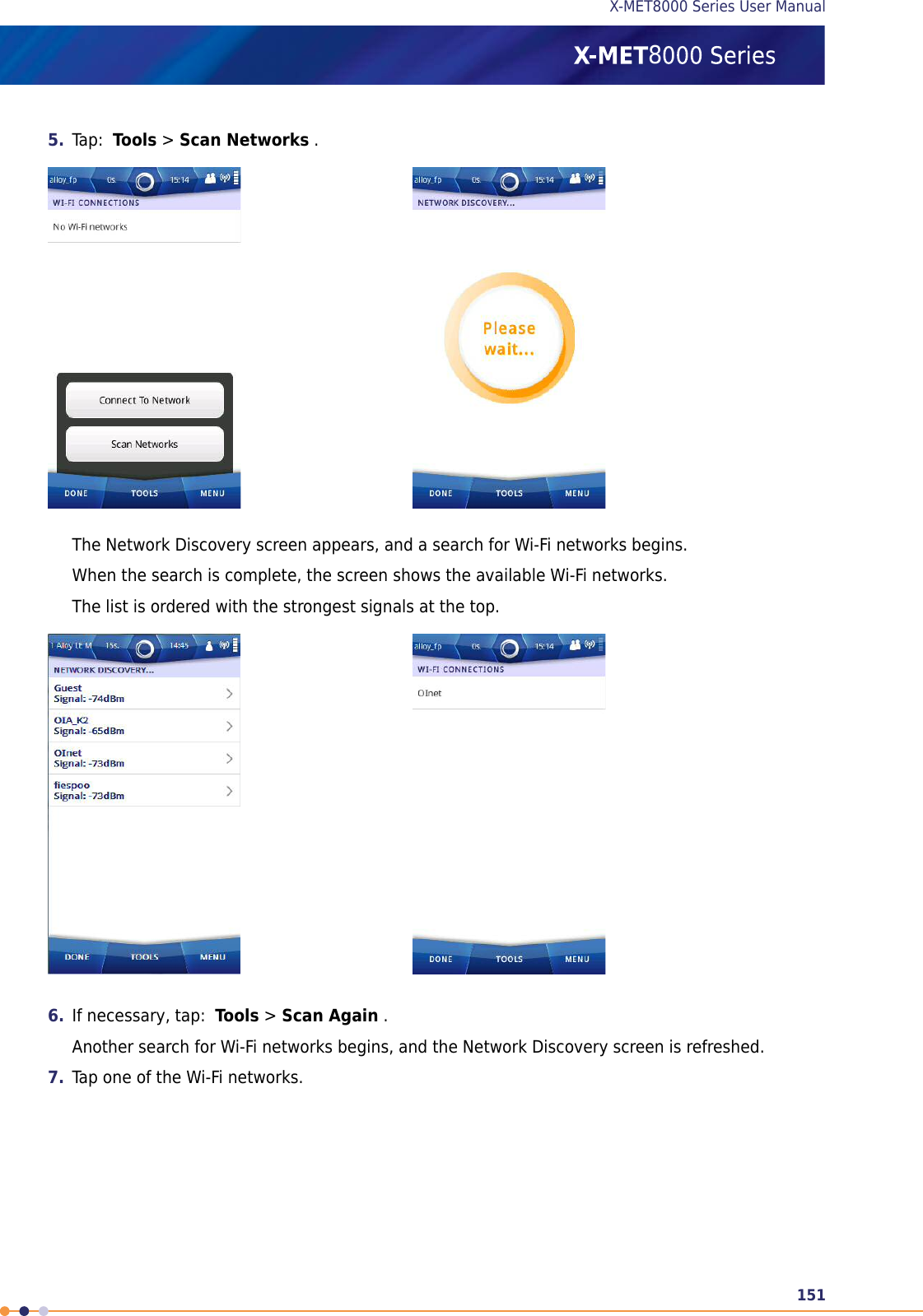
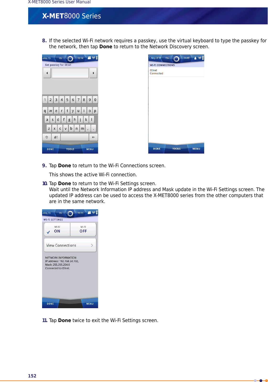
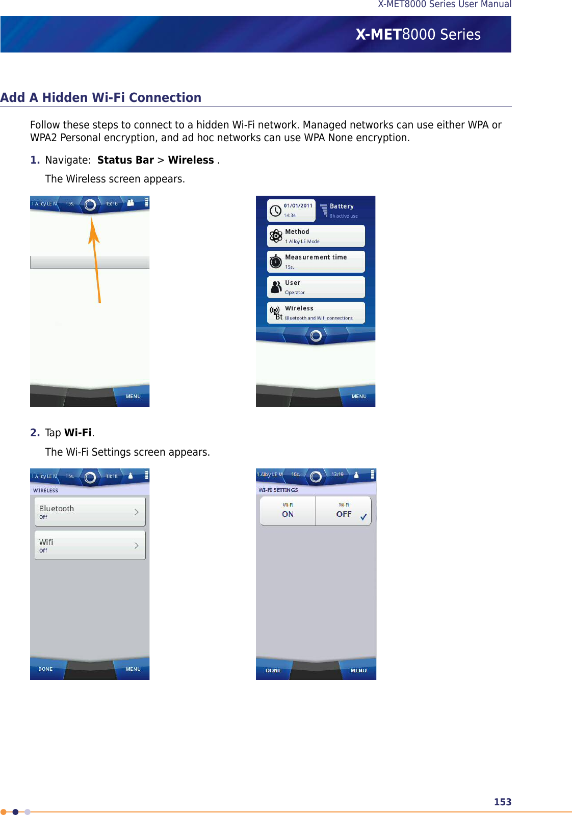
User Manual part 2
6.
User Manual part 3
User manual part 2
Navigation menu
Upload a User Manual
Namespaces
Wiki Guide
HTML
PDF
Info
Views
User Manual
Discussion / Help
Navigation