Oxford Instruments W2CBW003 802.11 b/g + Bluetooth Module User Manual part 3
Oxford Instruments 802.11 b/g + Bluetooth Module part 3
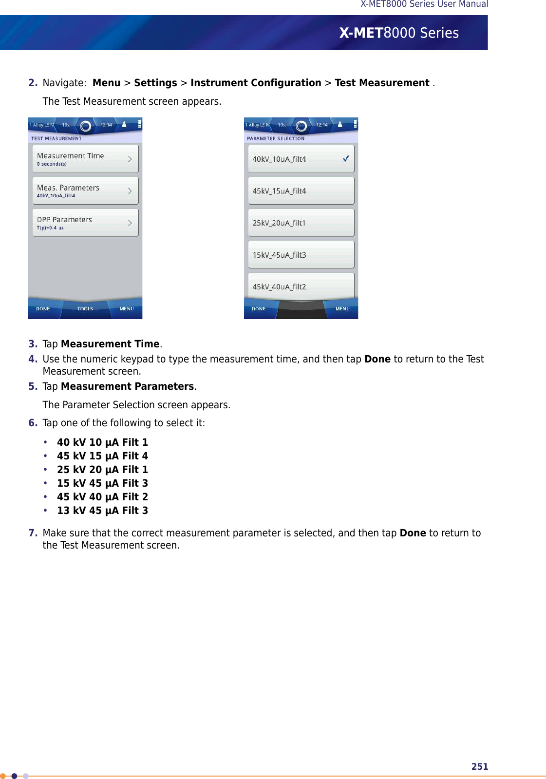
UserManual.wiki
>
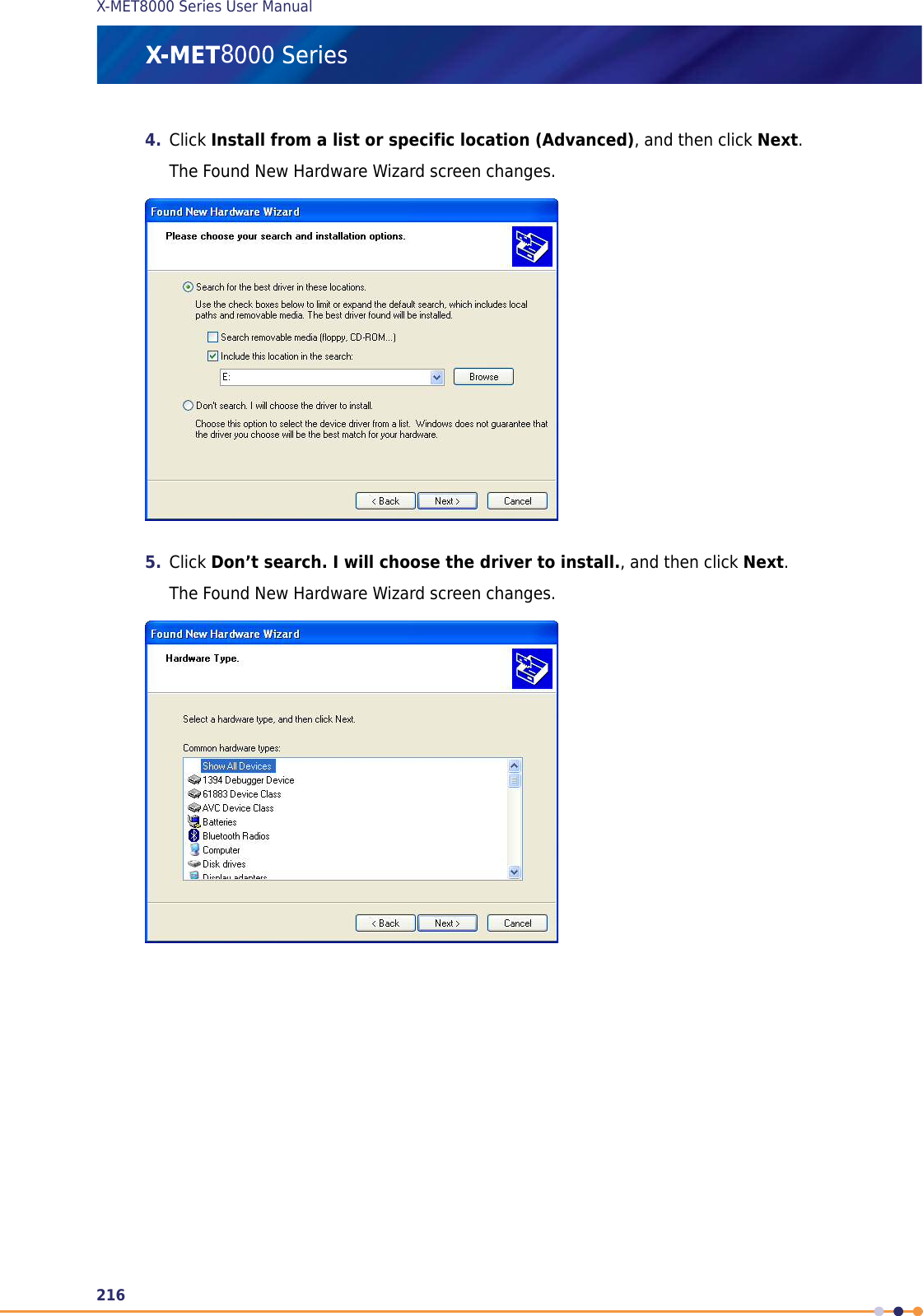
Oxford Instruments
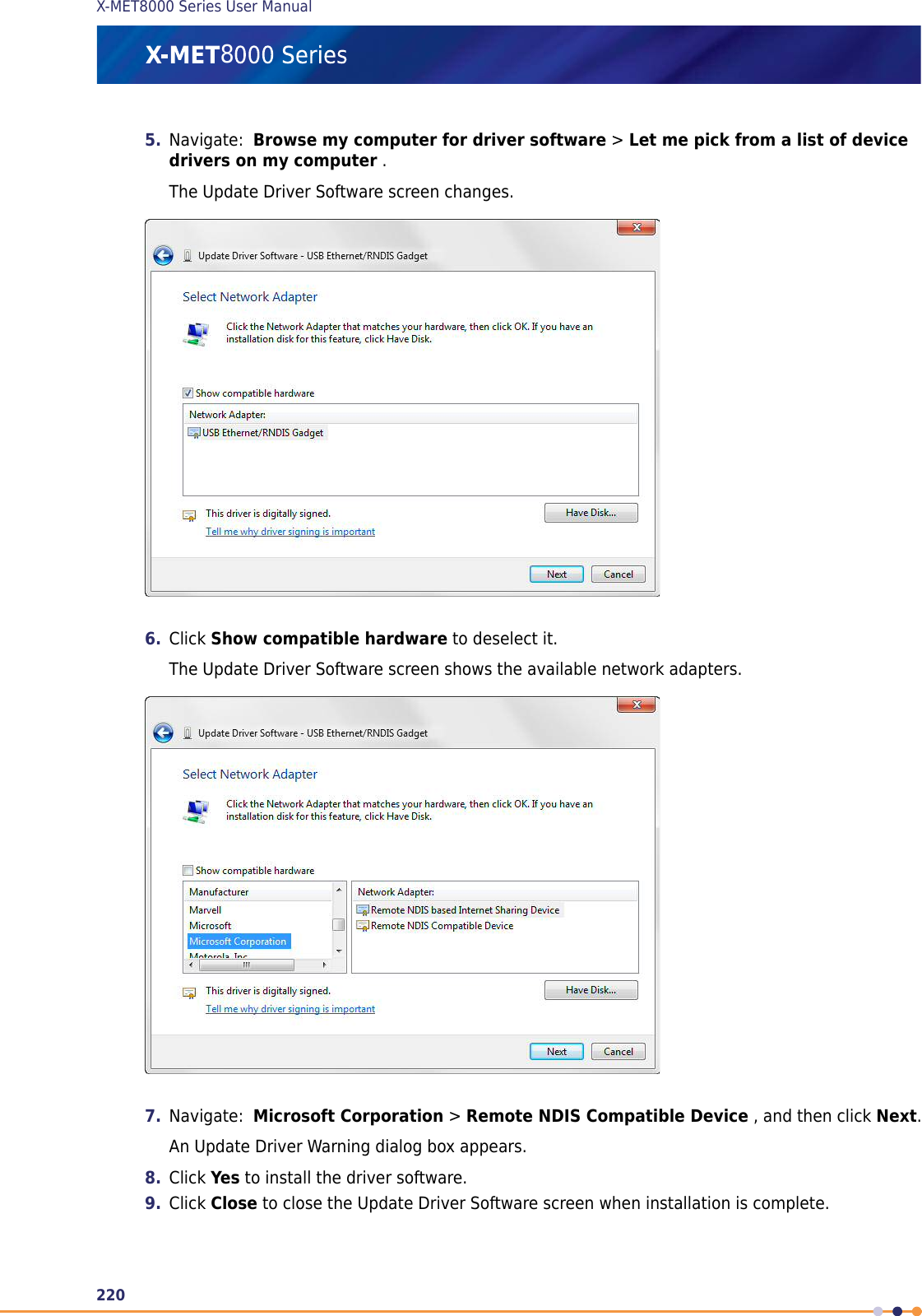
>
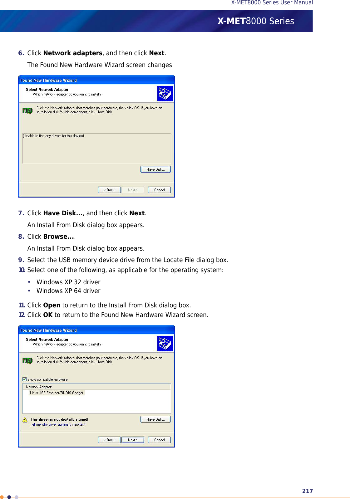
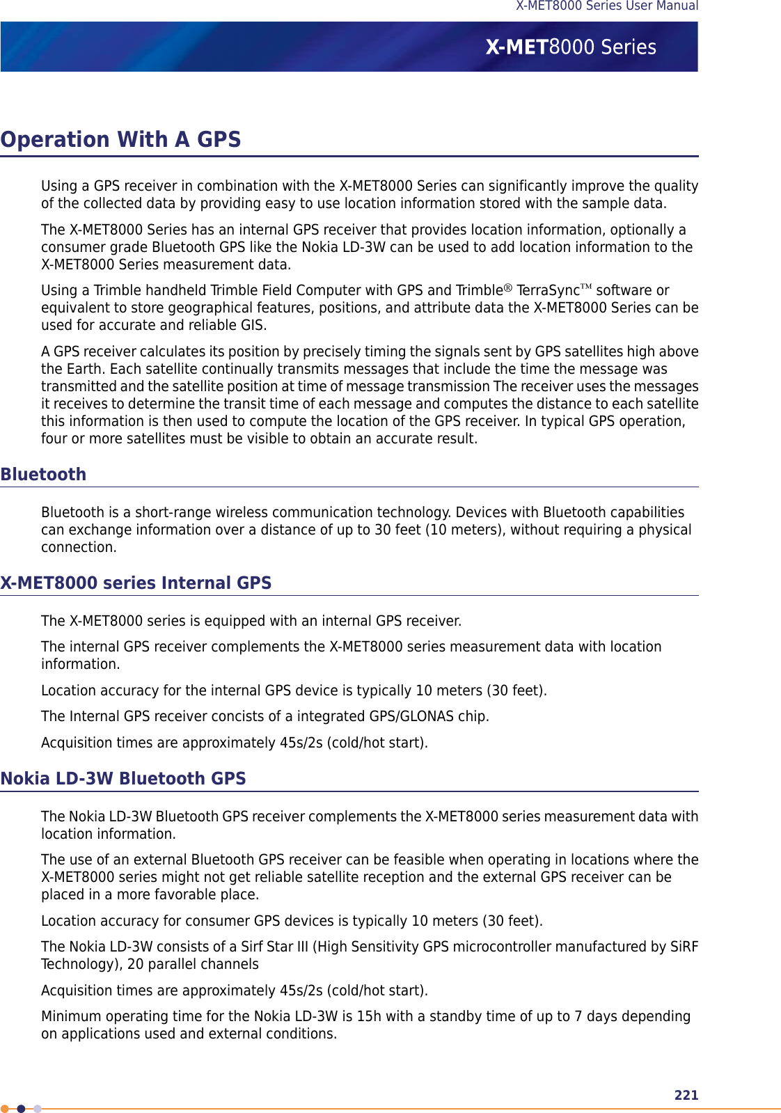
W2CBW003 User Manual
>
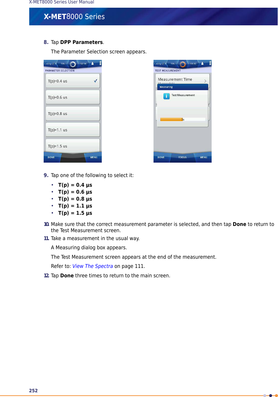
User manual part 3
Contents
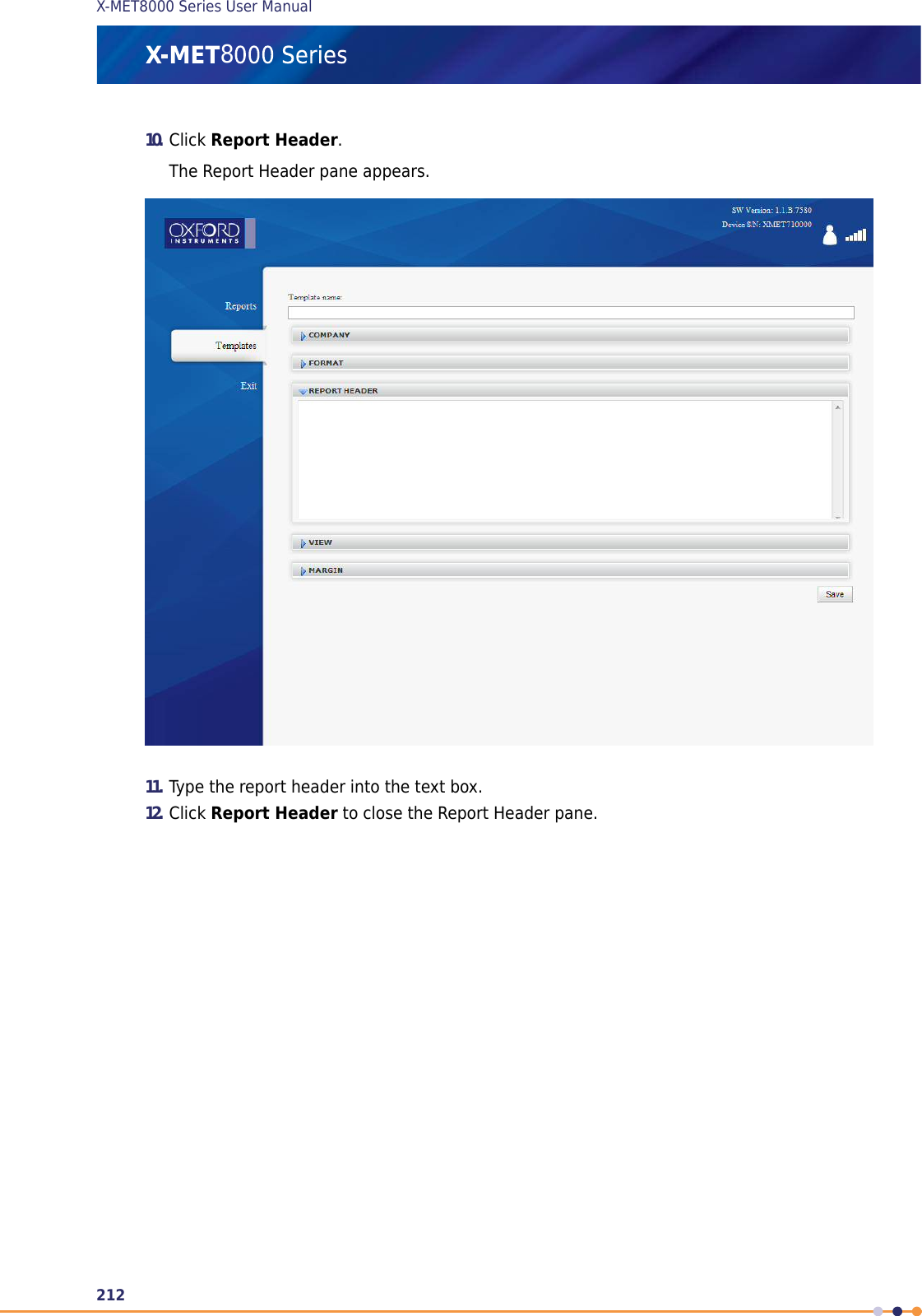
1.
User manual part 1
2.
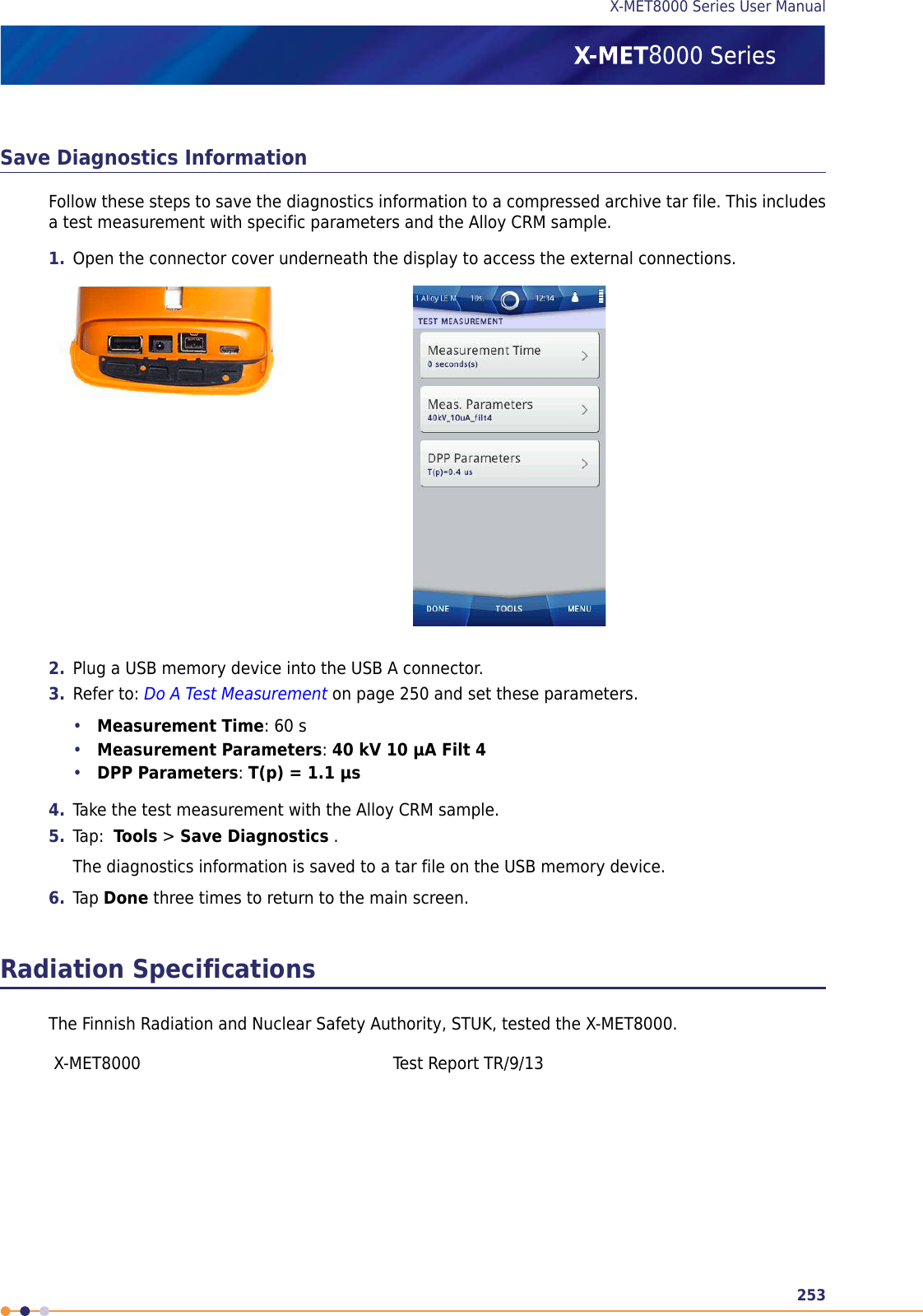
User manual part 2
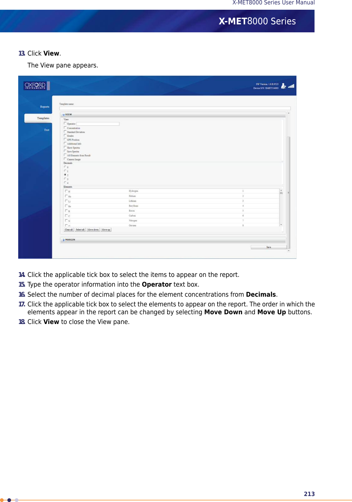
3.
User manual part 3
4.
User Manual part 1
5.
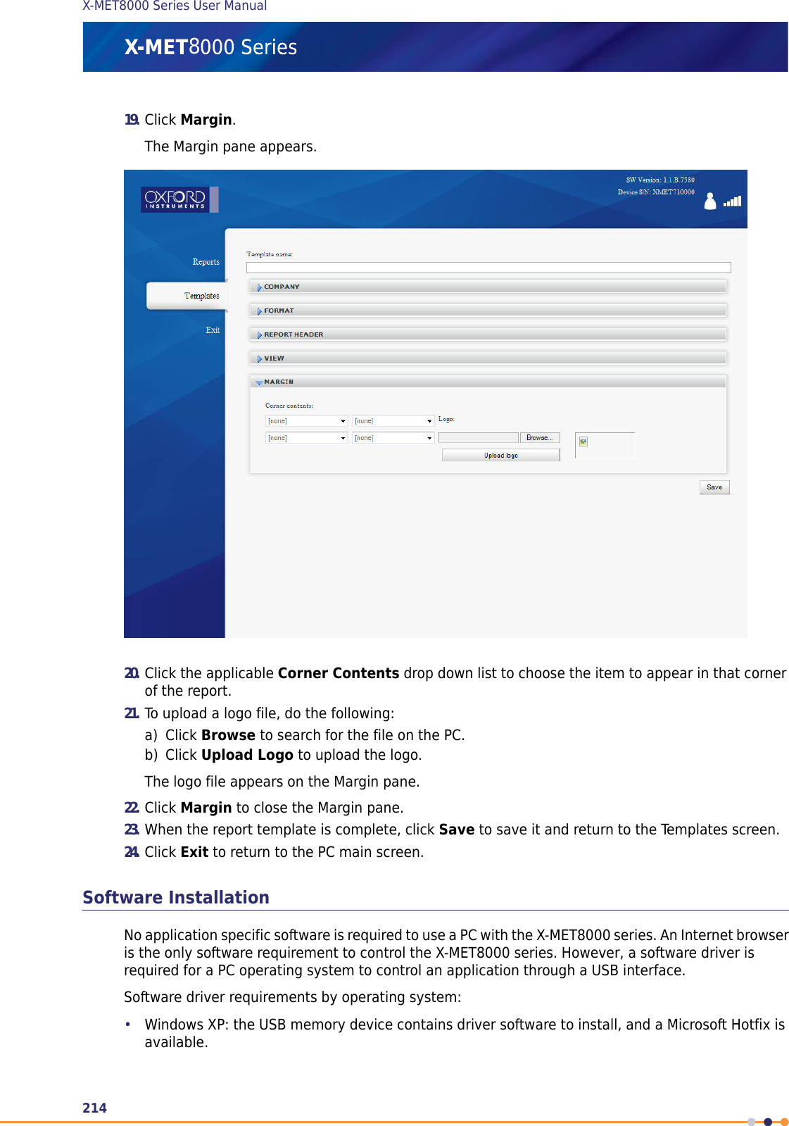
User Manual part 2
6.
User Manual part 3
User manual part 3
Navigation menu
Upload a User Manual
Namespaces
Wiki Guide
HTML
PDF
Info
Views
User Manual
Discussion / Help
Navigation

![<password>password</password> <buffersize>0</buffersize> <retryinterval>60</retryinterval> <send-measurements>false</send-measurements> <send-spectrums>false</send-spectrums></pushclientsettings>The parameters are explained below.Push APIThe X-MET8000 series can be configured to send new measurements and spectra to a specified URLin HTTP POST requests. The push client is enabled and configured by performing a HTTP PUT requestto the /pushclientsettings resource in the format defined above. If the PUT request was successful,HTTP Status code 200 OK is returned and the new settings come to effect immediately. In case of anerror, HTTP Status code 400 Bad Request is returned and settings are not modified. Settings are savedand restored when the X-MET8000 series device is restarted.The following parameters can be set:•server-url: Valid server URL to the root directory of the push-server.•user: Username used in HTTP Basic authentication.•password: Password used in HTTP basic authentication.•buffersize: The amount of extra spectra and measurement results that are stored in a queue incase of a connection error. Buffer size must be an integer in range [0, 100]. No data is sent ifbuffer size is set to 0.•retryinterval: Interval in second between retry attempts in case of a connection error. Value mustbe a positive integer.•send-measurements: Configures if measurements results are sent to the server. Valid valuesare "true" and "false".•send-spectrums: Configures if spectra are sent to the server. Valid values are "true" and "false".Push Client sends spectra and measurement results to the server whenever a new spectrum or resultis finished. Measurements are sent in a HTTP POST request to the URL<server-url>/[serial-number]/measurements where [serial-number] is the serial number of theX-MET7000 seriesMeasurement results are sent in the same XML format that is used for the /measurements resource,except that the Spectrums element containing links to spectra is replaced with a SpectrumDataelement containing the data directly.Spectra are sent to the URL <server-url>/[serial-number]/spectrums in the same XML formatused for the /spectrum resource.Push Client uses HTTP Basic authentication when communicating with the server. In case of an error,Push Client keeps spectra and measurements in the queue and tries sending again every<retryinterval> seconds.249X-MET8000 Series User Manual8](https://usermanual.wiki/Oxford-Instruments/W2CBW003.User-manual-part-3/User-Guide-2188387-Page-49.png)