PBE Europe as Axell Wireless 50-1465SERIES 50-146501 VHF Channelised Air Interface User Manual 50 146501 50 146601 50 146701HBKM
Axell Wireless 50-146501 VHF Channelised Air Interface 50 146501 50 146601 50 146701HBKM
Contents
- 1. User Manual 1 of 2
- 2. User Manual 2 of 2
User Manual 1 of 2

Aerial Facilities Limited
Technical Literature Bronx Justice Centre Radio Repeaters
Handbook Number: 80-283501HBKM Issue No. A Date:15/10/2006 Page 1 of 86
Aerial Facilities Limited
New York Justice Centre
Radio Repeater Equipment
For
GPD Telecom Inc.
AFL Works Order: Q114828
AFL product part Nǀs.: 50-146501 (VHF Repeater)
50-146601 (UHF Repeater)
50-146701 (800MHz Repeater)

Bronx Justice Centre Radio Repeaters
Handbook Number: 80-283501HBKM Page: 2 of 86
Table of Contents
1. INTRODUCTION ............................................................................................................5
Scope and Purpose of Document.................................................................................................... 5
Limitation of Liability Notice ............................................................................................................ 5
2. SAFETY CONSIDERATIONS ........................................................................................6
2.1 Earthing of Equipment......................................................................................................... 6
2.2 Electric Shock Hazard.......................................................................................................... 6
2.3 RF Radiation Hazard ............................................................................................................ 6
2.4 Chemical Hazard .................................................................................................................. 7
2.5 Laser Safety.......................................................................................................................... 7
2.6 Emergency Contact Numbers ............................................................................................. 7
3. EQUIPMENT OVERVIEW ..............................................................................................8
3.1 System Description.............................................................................................................. 8
3.2 Whole System Diagram, Drg. # 50-146581 ......................................................................... 9
4. SYSTEM DETAILS.......................................................................................................10
4.1 VHF Channel Selective Cell Enhancer Rack (50-146501) ............................................... 10
4.1.1 VHF Cell Enhancer Rack Description .............................................................................. 10
4.1.2 VHF Cell Enhancer Rack Electrical Specification ............................................................ 10
4.1.3 VHF Cell Enhancer Rack Mechanical Specification......................................................... 11
4.1.4 VHF Cell Enhancer Rack Parts List ................................................................................. 11
4.1.5 VHF Downlink O/P Combiner Shelf (50-146502) ............................................................. 12
4.1.5.P VHF Downlink O/P Combiner Shelf Photographs...................................................................12
4.1.5.1 Description ..............................................................................................................................13
4.1.5.2 Technical Specification ...........................................................................................................13
4.1.6.3 Parts List .................................................................................................................................13
4.1.5.4 System Diagram, Drg. # 50-146582 .......................................................................................14
4.1.6 VHF Uplink I/P Splitter Shelf (50-146503)........................................................................ 15
4.1.6.P VHF Uplink I/P Splitter Shelf Photographs..............................................................................15
4.1.6.1 Description ..............................................................................................................................16
4.1.6.2 Technical Specification ...........................................................................................................16
4.1.6.3 Parts List .................................................................................................................................16
4.1.6.4 System Diagram, Drg. # 50-146583 .......................................................................................17
4.1.7 VHF Duplex BDA Channel 1 Shelf (50-146504) .............................................................. 18
4.1.7.P VHF Duplex BDA Channel 1 Shelf Photographs ....................................................................18
4.1.7.1 Description ..............................................................................................................................19
4.1.7.2 Technical Specification ...........................................................................................................19
4.1.7.3 Parts List .................................................................................................................................20
4.1.7.4 System Diagram, Drg. # 50-146584 .......................................................................................21
4.1.8 VHF Duplex BDA Channel 2 Shelf (50-146505) .............................................................. 22
4.1.8.P VHF Duplex BDA Channel 2 Shelf Photographs ....................................................................22
4.1.8.1 Description ..............................................................................................................................22
4.1.8.2 Technical Specification ...........................................................................................................22
4.1.8.3 Parts List .................................................................................................................................22
4.1.8.4 System Diagram......................................................................................................................23
4.1.9 VHF Simplex BDA Channel 3A Shelf (50-146506) .......................................................... 24
4.1.9.P VHF Simplex BDA Photographs .............................................................................................24
4.1.9.1 Description ..............................................................................................................................25
4.1.9.2 Technical Specification ...........................................................................................................25
4.1.9.3 System Diagram, Drg. # 50-146586 .......................................................................................26
4.1.9.4 Parts List .................................................................................................................................27
4.1.10 VHF Simplex BDA Channel 3B Shelf (50-146507) .......................................................... 28
4.1.10.P VHF Simplex BDA Channel 3B Photographs .........................................................................28
4.1.10.1 Description ..............................................................................................................................28
4.1.10.2 Technical Specification ...........................................................................................................28
4.1.10.3 System Diagram, Drg. # 50-146587 .......................................................................................29
4.1.10.4 Parts List .................................................................................................................................30
4.1.11 VHF Simplex BDA Channel 4 Shelf (50-146508)............................................................. 31
4.1.11.P VHF Simplex BDA Channel 4 Shelf Photographs ..................................................................31
4.1.11.1 Description ..............................................................................................................................31

Bronx Justice Centre Radio Repeaters
Handbook Number: 80-283501HBKM Page: 3 of 86
4.1.11.2 Technical Specification ...........................................................................................................31
4.1.11.3 System Diagram, Drg. # 50-146588 .......................................................................................32
4.1.11.4 Parts List .................................................................................................................................33
4.1.12 Downlink I/P Splitter (50-146509).....................................................................................34
4.1.12.P Downlink Input Splitter Photographs.......................................................................................34
4.1.12.1 Description ..............................................................................................................................35
4.1.12.2 Technical Specification ...........................................................................................................35
4.1.12.3 Parts List .................................................................................................................................35
4.1.12.4 System Diagram, Drg. # 50-146589 .......................................................................................36
4.1.13 Downlink O/P Combiner (50-146510) ..............................................................................37
4.1.13.P Downlink O/P Combiner Photographs ....................................................................................37
4.1.13.1 Description ..............................................................................................................................38
4.1.13.2 Technical Specification ...........................................................................................................38
4.1.13.3 Parts List .................................................................................................................................38
4.1.13.4 System Diagram......................................................................................................................39
4.1.14 VHF/UHF 24V Power Supply Shelf (50-146512) ............................................................. 40
4.1.14.P VHF/UHF Power supply Shelf Photographs ...........................................................................40
4.1.14.1 VHF/UHF PSU Shelf Description............................................................................................41
4.1.14.2 VHF/UHF PSU Shelf Technical Specification .........................................................................41
4.1.14.3 VHF/UHF PSU Shelf Parts List ...............................................................................................42
4.1.14.4 VHF/UHF PSU Shelf System Diagram, (needs new drawing) ...............................................43
4.2 UHF Channel Selective Cell Enhancer Rack (50-146601) ............................................... 44
4.2.1 Description ....................................................................................................................... 44
4.2.2 Electrical Specification ..................................................................................................... 44
4.2.3 Mechanical Specification.................................................................................................. 44
4.2.4 Parts List .......................................................................................................................... 45
4.2.5 Downlink Combiner Shelf (50-146602) ............................................................................ 46
4.2.5.P Downlink Combiner Photographs ...........................................................................................46
4.2.5.1 Description ..............................................................................................................................47
4.2.5.2 Technical Specification ...........................................................................................................47
4.2.5.3 Parts List .................................................................................................................................47
4.2.5.4 System Diagram, Drg. # 50-146682 .......................................................................................48
4.2.6 Uplink Splitter Shelf (60-146603) ..................................................................................... 49
4.2.6.P Uplink Splitter Shelf Photographs ...........................................................................................49
4.2.6.1 Description ..............................................................................................................................50
4.2.6.2 Technical Specification ...........................................................................................................50
4.6.2.3 Parts List .................................................................................................................................50
4.2.6.4 System Diagram, Drg. # 50-146683 .......................................................................................51
4.2.7 UHF Duplex Channel 1 BDA (50-146604) ....................................................................... 52
4.2.7.P Duplex Shelf Photographs (hardware identical, only 1 shelf shown)......................................52
4.2.7.1 Description ..............................................................................................................................53
4.2.7.2 Technical Specification ...........................................................................................................53
4.2.7.3 Parts List .................................................................................................................................54
4.2.7.4 UHF Duplex Channel 1 BDA System Diagram Drg. # 60-146684..........................................55
4.2.8 UHF Duplex Channel 2 BDA (50-146605) ....................................................................... 56
4.2.8.1 UHF Duplex Channel 2 BDA System Diagram, Drg. # 50-146685.........................................56
4.2.9 UHF Duplex Channel 3 BDA (50-146606) ....................................................................... 57
4.2.9.1 UHF Duplex Channel 3 BDA System Diagram, Drg. # 50-146686.........................................57
4.2.10 UHF Duplex Channel 4 BDA (50-146607) ....................................................................... 58
4.2.10.1 UHF Duplex BDA Channel 4 System Diagram, Drg. # 50-146687.........................................58
4.2.11 UHF Duplex Channel 5 BDA (50-146608) ....................................................................... 59
4.2.11.1 UHF Duplex Channel 5 System Diagram, Drg. # 50-146688 .................................................59
4.2.12 UHF Duplex Channel 6 BDA (50-146612) ....................................................................... 60
4.2.12.1 UHF Duplex Channel 6 BDA System Diagram, Drg. # 50-146692.........................................60
4.2.13 UHF Uplink Combiner Shelf (50-146609)......................................................................... 61
4.2.13.P UHF Uplink Combiner Shelf Photographs ..............................................................................61
4.2.13.1 Description ..............................................................................................................................62
4.2.13.2 Technical Specification ...........................................................................................................62
4.2.13.3 Parts List .................................................................................................................................62
4.2.13.4 UHF Uplink Combiner Shelf System Diagram, Drg. # 50-146689..........................................63
4.2.14 UHF Downlink Splitter Shelf (50-146610) ........................................................................ 64
4.2.14.P UHF Downlink Splitter Shelf Photographs ..............................................................................64
4.2.14.1 Description ..............................................................................................................................65
4.2.14.2 Technical Specification ...........................................................................................................65

Bronx Justice Centre Radio Repeaters
Handbook Number: 80-283501HBKM Page: 4 of 86
4.2.14.3 Parts List .................................................................................................................................65
4.2.14.4 UHF Downlink Splitter Shelf System Diagram, Drg. # 50-146690..........................................66
4.3 800MHz Channel Selective Cell Enhancer Rack (50-146701) ......................................... 67
4.3.1 Description ....................................................................................................................... 67
4.3.2 Technical Specification..................................................................................................... 67
4.3.3 Parts List .......................................................................................................................... 67
4.3.4 800MHz Channel Selective C.E. System Diagram, Drg. # 50-146782............................. 68
4.4 Channel Selective Uplink & Downlink Shelf (50-146702)................................................ 69
4.4.P Uplink & Downlink Shelf Photographs.............................................................................. 69
4.4.1 Uplink & Downlink Shelf Description ................................................................................ 70
4.4.2 Uplink & Downlink Shelf Electrical Specifications ............................................................ 70
4.4.3 Uplink & Downlink Shelf Mechanical Specifications......................................................... 70
4.4.4 Uplink & Downlink Shelf System Diagram See section 4.3.4........................................... 70
4.4.5 Uplink & Downlink Shelf Parts List ................................................................................... 71
4.5 800MHz Downlink Power Amplifier Shelf (50-146703) .................................................... 72
4.5.P Downlink Power Amplifier Shelf Photographs .................................................................. 72
4.5.1 Downlink Power Amplifier Shelf Description ....................................................................73
4.5.2 Downlink Power Amplifier Shelf Electrical Specifications................................................. 73
4.5.3 Downlink Power Amplifier Shelf Mechanical Specification............................................... 73
4.5.4 Downlink Power Amplifier Shelf System Diagram............................................................ 73
4.5.5 Downlink Power Amplifier Shelf Parts List .......................................................................74
4.6 Multiband Combiner Shelf (50-146705) ............................................................................ 75
4.6.P Multiband Combiner Shelf Photographs........................................................................... 75
4.6.1 Multiband Combiner Shelf Description ............................................................................. 76
4.6.2 Multiband Combiner Shelf Technical Specification .......................................................... 76
4.6.3 Multiband Combiner Shelf Parts List ................................................................................ 76
4.6.4 Multiband Combiner Shelf System Diagram, Drg. # 50-146785....................................... 77
5. INSTALLATION............................................................................................................78
5.1 Initial Installation Record................................................................................................... 78
6. FAULT FINDING & MAINTENANCE ...........................................................................78
6.1 General Fault Finding Procedures.................................................................................... 78
5.2 Downlink ............................................................................................................................. 79
5.3 Uplink .................................................................................................................................. 79
5.4 Fault repair.......................................................................................................................... 79
5.5 Checking service................................................................................................................ 79
5.6 Service Support.................................................................................................................. 79
5.7 Tools & Test Equipment .................................................................................................... 79
5.8 General Maintenance Procedures .................................................................................... 80
5.9 Module Removal (LNAs, general procedure)................................................................... 80
5.10 Module Replacement (general) ......................................................................................... 80
5.11 Power Amplifiers ................................................................................................................ 80
5.12 Low Power Amplifier Replacement .................................................................................. 81
5.13 Module Transportation ...................................................................................................... 81
APPENDIX A......................................................................................................................... 82
Amendment List Record Sheet...................................................................................................... 82
Glossary of Terms........................................................................................................................... 83
Key to AFL Drawing Symbols ........................................................................................................ 84
EC Declaration of Conformity ........................................................................................................ 85
APPENDIX B......................................................................................................................... 86
Initial Equipment Set-Up Calculations ..........................................................................................86
General Information........................................................................................................................ 86
Antenna Systems ........................................................................................................................... 86
Initial Parameters ........................................................................................................................... 86
Downlink Calculations .................................................................................................................... 86
Uplink Calculations......................................................................................................................... 86

Bronx Justice Centre Radio Repeaters
Handbook Number: 80-283501HBKM Page: 5 of 86
1. INTRODUCTION
Scope and Purpose of Document
This handbook is for use solely with the equipment identified by the AFL Part Number shown on the
front cover. It is not to be used with any other equipment unless specifically authorised by Aerial
Facilities Limited. This is a controlled release document and, as such, becomes a part of Aerial
Facilities’ Total Quality Management System. Alterations and modification may therefore only be
performed by Aerial Facilities Ltd.
AFL recommends that the installer of this equipment familiarise themselves with the safety and
installation procedures contained within this document before installation commences.
The purpose of this handbook is to provide the user/maintainer with sufficient information to service
and repair the equipment to the level agreed. Maintenance and adjustments to any deeper level must
be performed by AFL, normally at the company’s repair facility in Chesham, England.
This handbook has been prepared in accordance with BS 4884, and AFL’s Quality procedures, which
maintain the company’s registration to BS EN ISO 9001:2000 and to the R&TTE Directive of the
European Parliament. Copies of the relevant certificates and the company Quality Manual can be
supplied on application to the Quality Manager.
This document fulfils the relevant requirements of Article 6 of the R&TTE Directive.
Limitation of Liability Notice
This manual is written for the use of technically competent operators/service persons. No liability is
accepted by AFL for use or misuse of this manual, the information contained therein, or the
consequences of any actions resulting from the use of the said information, including, but not limited
to, descriptive, procedural, typographical, arithmetical, or listing errors.
Furthermore, AFL does not warrant the absolute accuracy of the information contained within this
manual, or its completeness, fitness for purpose, or scope.
AFL has a policy of continuous product development and enhancement, and as such, reserves the
right to amend, alter, update and generally change the contents, appearance and pertinence of this
document without notice.
All AFL products carry a twelve month warranty from date of shipment. The warranty is expressly on a
return to base repair or exchange basis and the warranty cover does not extend to on-site repair or
complete unit exchange.
Bronx Justice Centre Radio Repeaters
Handbook Number: 80-283501HBKM Page: 6 of 86
2. SAFETY CONSIDERATIONS
2.1 Earthing of Equipment
Cell Enhancers supplied from the mains must be connected to grounded outlets and
earthed in conformity with appropriate local, national and international electricity supply
and safety regulations.
2.2 Electric Shock Hazard
Electrical shocks due to faulty mains driven power supplies.
Whilst ever potentially present in any electrical equipment, such a condition would be
minimised by quality installation practice and thorough testing at:
a) Original assembly
b) Commissioning
c) Regular intervals, thereafter.
All test equipment to be in good working order prior to its use. High current power supplies can be
dangerous because of the possibility of substantial arcing. Always switch off during disconnection and
reconnection.
2.3 RF Radiation Hazard
RF radiation, (especially at UHF frequencies) arising from transmitter outputs
connected to AFL’s equipment, must be considered a safety hazard.
This condition might only occur in the event of cable disconnection, or because a
‘spare’ output has been left un-terminated. Either of these conditions would impair the
system’s efficiency. No investigation should be carried out until all RF power sources have been
removed. This would always be a wise precaution, despite the severe mismatch between the
impedance of an N type connector at 50, and that of free space at 377, which would severely
mitigate against the efficient radiation of RF power. Radio frequency burns could also be a hazard, if
any RF power carrying components were to be carelessly touched!
Antenna positions should be chosen to comply with requirements (both local & statutory) regarding
exposure of personnel to RF radiation. When connected to an antenna, the unit is capable of
producing RF field strengths, which may exceed guideline safe values especially if used with
antennas having appreciable gain. In this regard the use of directional antennas with backscreens
and a strict site rule that personnel must remain behind the screen while the RF power is on, is
strongly recommended.
Where the equipment is used near power lines or in association with temporary masts not having
lightning protection, the use of a safety earth connected to the case-earthing bolt is strongly advised.
Bronx Justice Centre Radio Repeaters
Handbook Number: 80-283501HBKM Page: 7 of 86
2.4 Chemical Hazard
Beryllium Oxide, also known as Beryllium Monoxide, or Thermalox™, is sometimes
used in devices within equipment produced by Aerial Facilities Ltd. Beryllium oxide
dust can be toxic if inhaled, leading to chronic respiratory problems. It is harmless if
ingested or by contact.
Products that contain beryllium are load terminations (dummy loads) and some power amplifier
transistors. These products can be identified by a yellow and black “skull and crossbones” danger
symbol (shown above). They are marked as hazardous in line with international regulations, but pose
no threat under normal circumstances. Only if a component containing beryllium oxide has suffered
catastrophic failure, or exploded, will there be any danger of the formation of dust. Any dust that has
been created will be contained within the equipment module as long as the module remains sealed.
For this reason, any module carrying the yellow and black danger sign should not be opened. If the
equipment is suspected of failure, or is at the end of its life-cycle, it must be returned to Aerial
Facilities Ltd for disposal.
To return such equipment, please contact the Quality Department, who will give you a Returned
Materials Authorisation (RMA) number. Please quote this number on the packing documents, and on
all correspondence relating to the shipment.
PolyTetraFluoroEthylene, (P.T.F.E.) and P.T.F.E. Composite Materials
Many modules/components in AFL equipment contain P.T.F.E. as part of the RF insulation barrier.
This material should never be heated to the point where smoke or fumes are evolved. Any person
feeling drowsy after coming into contact with P.T.F.E. especially dust or fumes should seek medical
attention.
2.5 Laser Safety
General working practices adapted from EN60825-2: 2000
“Do not stare with unprotected eyes or with any unapproved optical device at the fibre
ends or connector faces or point them at other people.”
“Use only approved filtered or attenuating viewing aids.”
“Any single or multiple fibre end or ends found not to be terminated (for example,
matched, spliced) shall be individually or collectively covered when not being worked
on. They shall not be readily visible and sharp ends shall not be exposed.”
“When using test cords, the optical power source shall be the last connected and the first
disconnected.”
“Use only approved methods for cleaning and preparing optical fibres and optical connectors.”
Always keep optical connectors covered to avoid physical damage
Do not allow any dirt/foreign material ingress on the optical connector bulkheads.
The optical fibre jumper cable maximum bend radius is 3cm; any smaller radii may result in optical
cable breakage or excessive transmission losses.
Note: Not all AFL products use fibre optic units and they are NOT weather proof.
2.6 Emergency Contact Numbers
The AFL Quality Department can be contacted on:
Telephone +44 (0)1494 777000
Fax +44 (0)1494 777002
E-mail qa@aerialfacilities.com

Bronx Justice Centre Radio Repeaters
Handbook Number: 80-283501HBKM Page: 8 of 86
3. EQUIPMENT OVERVIEW
3.1 System Description
The New York Justice Centre needs three different frequency bands of radio coverage within its
designated areas, each having specific channel allocations, some of which are simplex type, i.e. Tx &
RX on a single frequency, and some duplex where the Tx & Rx are on two different frequencies so
that both parties may transmit (or receive) simultaneously.
The AFL equipment supplied for this task is in several different parts:
VHF Channel selective Cell Enhancer 150MHz band, 5 channels (50-146501)
UHF Channel Selective Cell Enhancer 400MHz band, 6 channels (50-146601)
800MHz Channel Selective Cell Enhancer 800MHz band, 2 channels (50-146701)
Multi-Band Combiner All three frequency bands (80-146705)
All the cell enhancers have two switched attenuators in each path, a 0-30dB device to adjust the
signal level entering the channel selective module, and a 0-15dB unit which varies the output power
(after the channel module) that drives the leaky feeder antennas. In this way the system may be finely
tuned to both receive and transmit at the correct levels.
Each cell enhancer will be described separately in this document but where enhancers have common
modules, these will be detailed only once.
An alarm system is fitted that monitors all active devices and is easily integrated into any series ‘loop’
type system (where any break will trigger an alarm and show a local fault LED in the area where the
fault originated).
Bronx Justice Centre Radio Repeaters
Handbook Number: 80-283501HBKM Page: 9 of 86
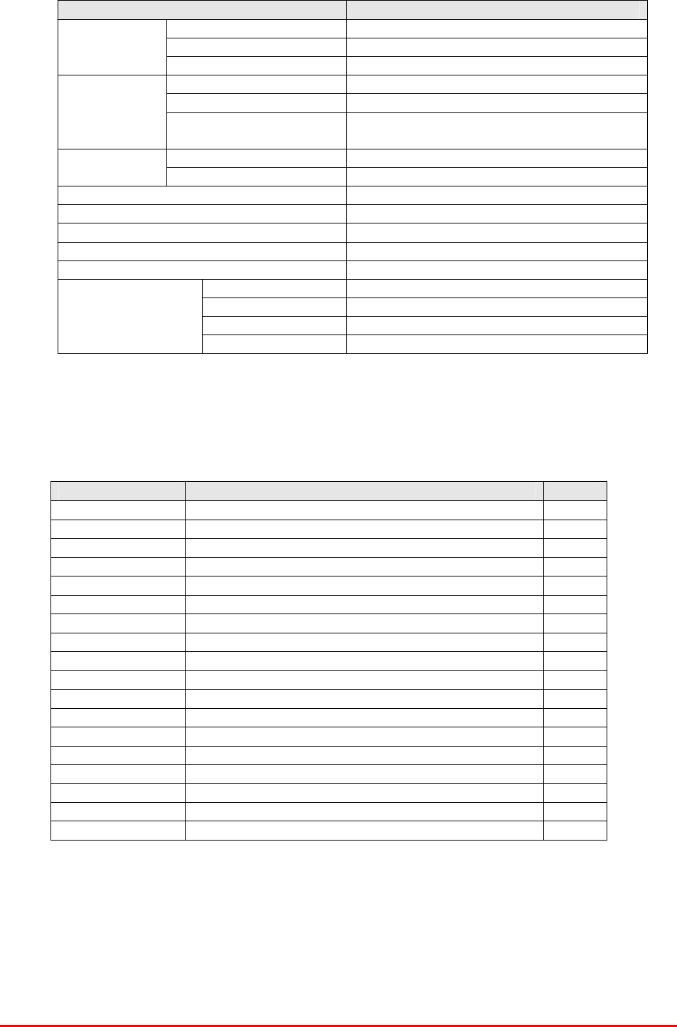
3.2 Whole System Diagram, Drg. # 50-146581

Bronx Justice Centre Radio Repeaters
Handbook Number: 80-283501HBKM Page: 10 of 86
4. SYSTEM DETAILS
4.1 VHF Channel Selective Cell Enhancer Rack (50-146501)
4.1.1 VHF Cell Enhancer Rack Description
The VHF cell enhancer, built into ten 19” wide shelves and housed in a 43U high equipment rack, is a
mixture of simplex (Tx & Rx on one frequency) and duplex (Tx & Rx on two separate frequencies)
systems, three simplex and two duplex. There are separate Rx and Tx antennæ for the VHF and UHF
bands and a composite antenna for the 800MHz bi-directional system. All VHF input channels, up and
downlink are selected by narrow band crystal filters, and all outputs have ferrite isolators fitted in
series to increase the isolation between adjacent channels and protect the transistors of the power
stages from possibly damaging reflections. Each active module has a volt-free relay contact pair
alarm which is looped to provide a normally-closed system. The inputs and outputs are handled by
combining and splitting shelves and the channel processing and amplification is all within the BDA
channel shelves.
The simplex Tx/Rx system relies upon noise-free paths to enable accurate detection and muting to
occur and for this reason it is not recommended to disturb these circuits as they are carefully set up
by AFL when system tested and should not be adjusted except by expert personnel.
A dedicated power supply shelf provides the DC needed by the VHF system, (a similar power supply
is used in the UHF system also), and all alarms are volt-free relay contact pairs, looped in each shelf
to provide a summary alarm with local failure indicator, suitable for integration into any such existing
system. No battery backup is provided for this system and so should the mains supply fail, this system
could not function.
4.1.2 VHF Cell Enhancer Rack Electrical Specification
PARAMETER SPECIFICATION
153.965MHz* (Ch. 1)
154.755MHz
154.785MHz
154.980MHz
158.925MHz* (Ch. 2)
VHF downlink
151.355MHz* (Ch. 1)
154.6575MHz* (Ch. 2)
154.755MHz
154.785MHz
VHF Frequencies:
154.980MHz
VHF uplink
Bandwidth: 15kHz (up & downlink)
Downlink Gain(Duplexed): 97 dB min
Downlink Gain(Simplex): 97 dB min
Uplink Gain (Duplex & Simplex): 100 dB min
Gain Adjustment: 0 – 15dB (in 1dB step)
Uplink Power: >2-5Watts
Downlink Power: >10Watts
AGC: Fitted in all channel selective modules
Noise Figure: <6dB (@ maximum gain)
VSWR: better than 1.5:1
Impedance: 50ȍ
RF Connectors: N type, female
Supply voltage: 110V AC (nominal) @ 43-63Hz
System power requirement: 24V DC @ <13A
1 Amplifiers Alarms Fitted:
(volt-free contacts/TTL) 2 PSU
* = duplex channel
Bronx Justice Centre Radio Repeaters
Handbook Number: 80-283501HBKM Page: 11 of 86
4.1.3 VHF Cell Enhancer Rack Mechanical Specification
PARAMETER SPECIFICATION
Height: 43U Standard Eldon Vented Rack
Width: 19" (482.6mm)
Rack
Depth: 600mm
Height: See parts lists
Width: 19" (482.6mm)
Shelves
Depth: <450mm(excluding heatsinks,
connectors, handles and feet)
operational: -20°C to +60°C Temperature
range storage: -40°C to +70°C
Weight: >100kg
Relative humidity: 5 – 95% non-condensing
RF Connectors: N type female
Environmental protection: IP44
Supply cable: Unit supplied from PSU shelf
Case: Iridite NCP coat
Heatsinks: None
Handles: Silver anodised aluminium alloy
Finish
Fascia: Painted to RAL7035
4.1.4 VHF Cell Enhancer Rack Parts List
AFL Part # Part Description Qty.
50-146502 VHF DOWNLINK O/P COMBINER 1
50-146503 VHF UPLINK I/P SPLITTER 1
50-146504 VHF DUPLEX BDA CHN 1 1
50-146505 VHF DUPLEX BDA CHN 2 1
50-146506 VHF SIMPLEX BDA CHN 3A 1
50-146507 VHF SIMPLEX BDA CHN 3B 1
50-146508 VHF SIMPLEX BDA CHN 4 1
50-146509 VHF DOWNLINK I/P SPLITTER 1
50-146510 VHF UPLINK O/P COMBINER 1
50-146512 VHF/UHF SYSTEM PSU 24V 1
80-054020 600mm DEEP SUPPORT BRACKET 20
80-063654 1U BLANKING PANEL (BS) RAL 7035 7
80-063655 2U BLANKING PANEL (BS) RAL 7035 2
90-100011 IEC MAINS LEAD '6 AMP' for USA 1
91-000002 N PLUG RG223:U 30
91-030002 N ADAPTOR PANEL FEMALE:FEMALE 4
97-500175 ELDON 43U 600 x 600 RACK (VENTED LID) 1
99-000082 PALLET 900 x 900 x 7ply FOR RACKS 1
Bronx Justice Centre Radio Repeaters
Handbook Number: 80-283501HBKM Page: 12 of 86
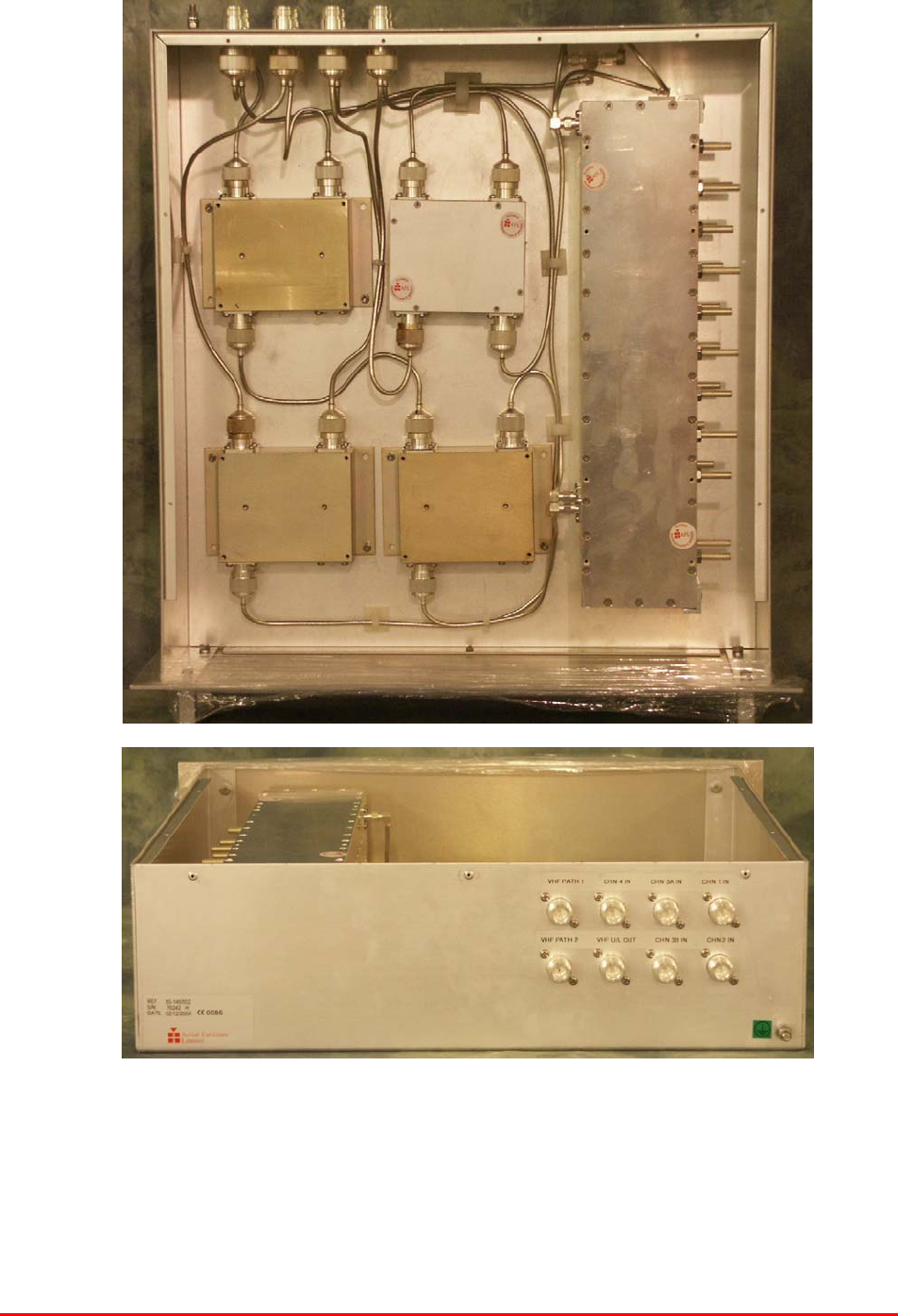
4.1.5 VHF Downlink O/P Combiner Shelf (50-146502)
4.1.5.P VHF Downlink O/P Combiner Shelf Photographs
Bronx Justice Centre Radio Repeaters
Handbook Number: 80-283501HBKM Page: 13 of 86
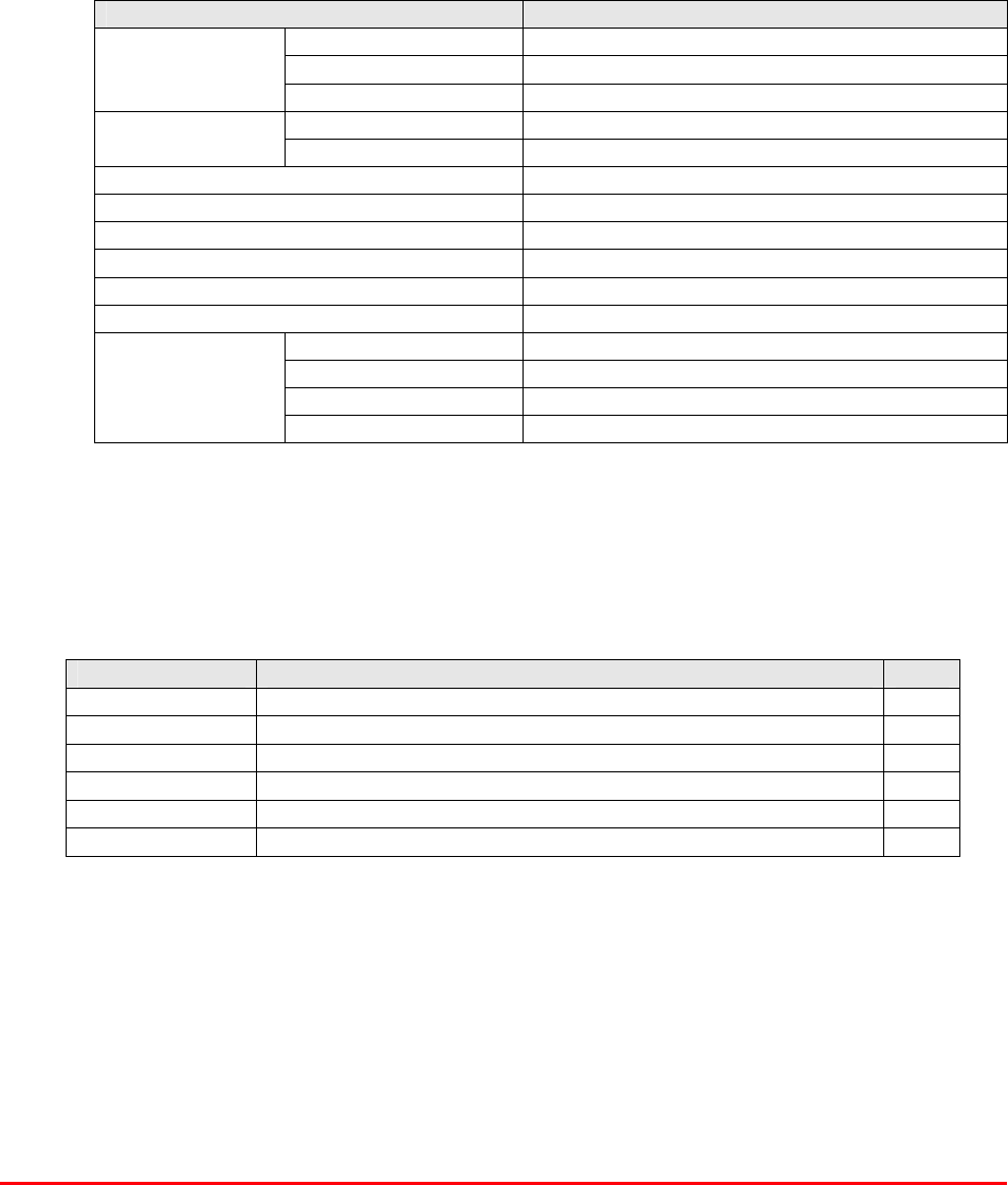
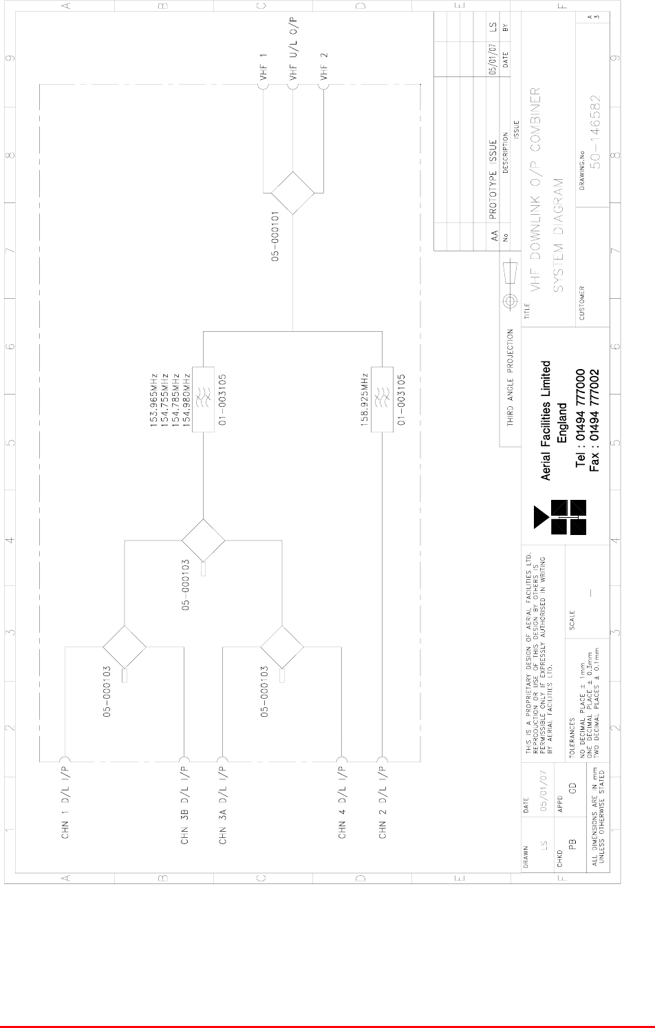
4.1.5.1Description
The five (downlink) channels are received from the output ports of the individual bi-directional
amplifier shelves and coupled together through hybrids, except for channel 2 which, being a
substantially higher frequency than the other four, has its own path through a dedicated bandpass
filter at the output of which the other four combined frequencies and channel 2 meet. The single
signal path is then passed through a divider to two equal level downlink output ports, VHF1 & VHF2.
This is a passive shelf and has no connection to the PSU and no alarms
4.1.5.2Technical Specification
PARAMETER SPECIFICATION
Height: 3U
Width: 19" (482.6mm)
Shelf
dimensions: Depth: <450mm (excluding connectors & handles)
operational: -20°C to +60°C Temperature
range: storage: -40°C to +70°C
Weight: <10kg
Frequency ranges passed: 153.965 to 154.980 & 158.925MHz
Impedance: 50ȍ
Humidity: 5 – 95% non-condensing
RF Connectors: N type female
Environmental protection: IP44
Case: Iridite NCP coat
Heatsinks: None
Handles: Silver anodised aluminium alloy
Finish
Fascia: Painted to RAL7035
4.1.6.3Parts List
AFL Part # Part Description Qty.
01-003105 SD NOTCH FILT.N 6 SECT.VHF H/B SMA 2
05-000101 TRANSMITTER HYBRID COUPLER (4 PORT) 1
05-000103 TX HYBRID COUPLER 3 PORT (NO HEATSINK) 3
19-000922K 3U CHASSIS KIT (450mm deep) 1
91-030002 N ADAPTOR PANEL FEMALE:FEMALE 8
91-130001 SMA ADAPT 'T' ALL FEMALE 3 GHz 1
Bronx Justice Centre Radio Repeaters
Handbook Number: 80-283501HBKM Page: 14 of 86
4.1.5.4System Diagram, Drg. # 50-146582
Bronx Justice Centre Radio Repeaters
Handbook Number: 80-283501HBKM Page: 15 of 86
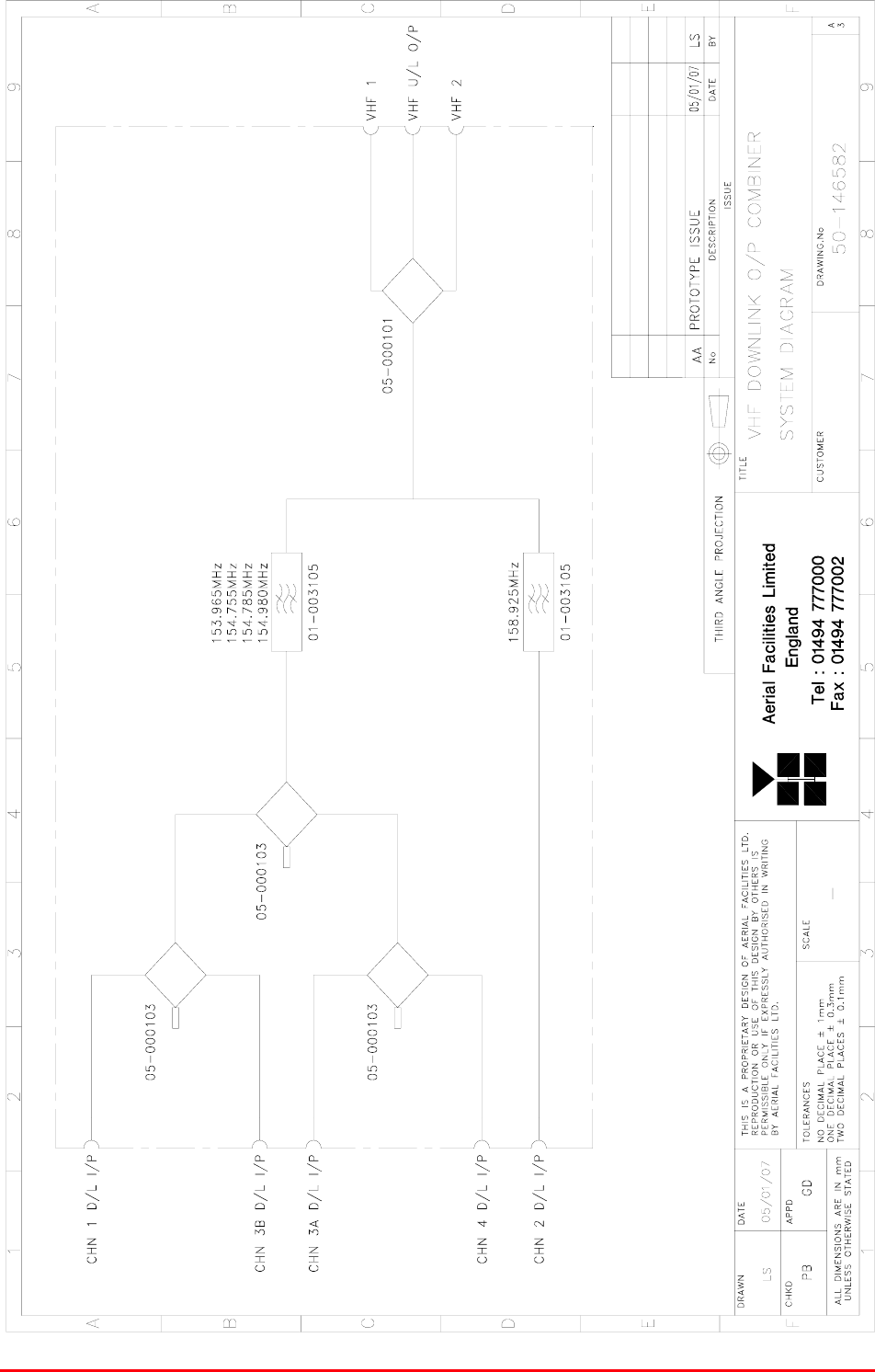
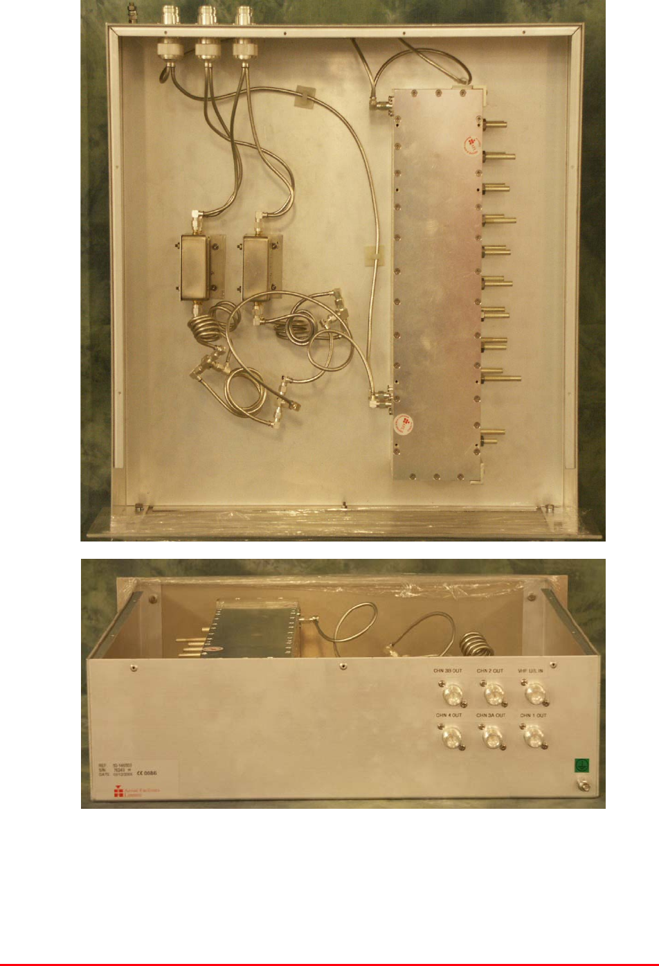
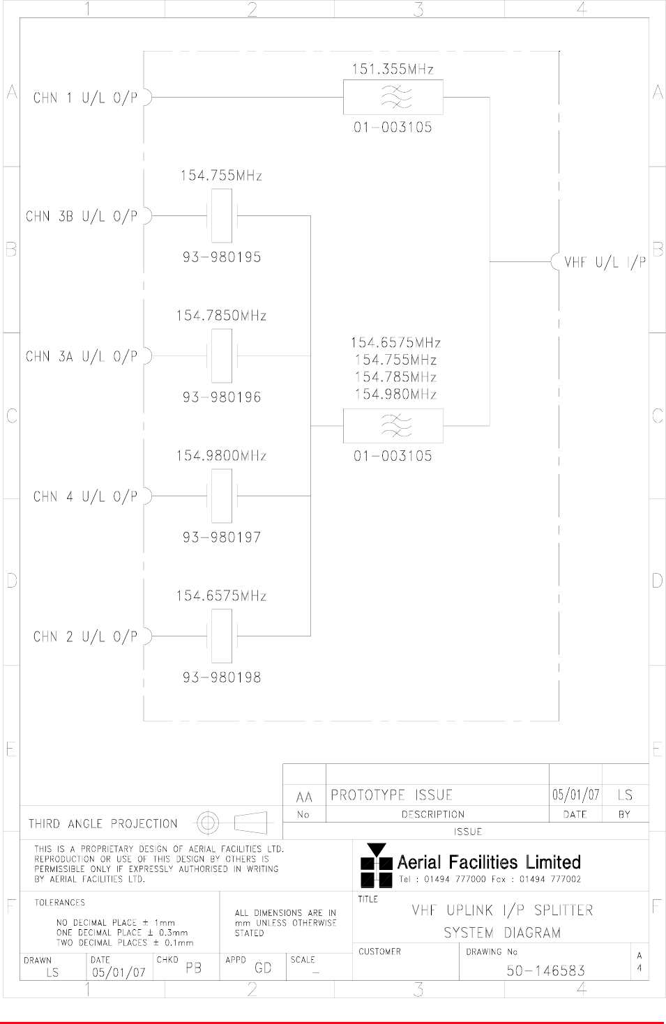
4.1.6 VHF Uplink I/P Splitter Shelf (50-146503)
4.1.6.P VHF Uplink I/P Splitter Shelf Photographs
Bronx Justice Centre Radio Repeaters
Handbook Number: 80-283501HBKM Page: 16 of 86
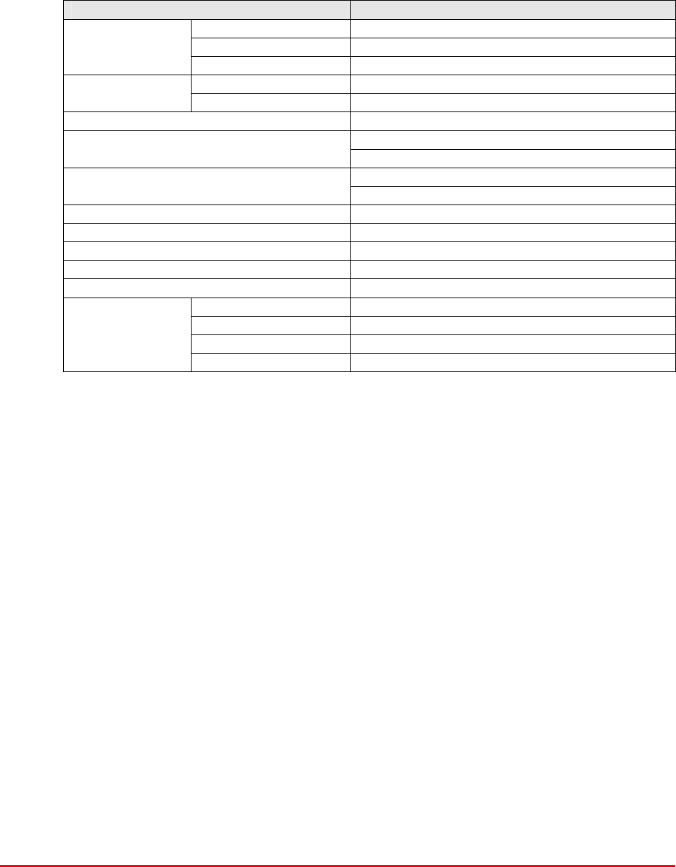
4.1.6.1Description
This shelf receives the single uplink RF from the antenna(s) and, similar to the downlink, one of the
five channels is substantially different in frequency to the other four. This means that channel 1 is
routed through a dedicated bandpass filter and the other four signals together also use a single filter.
The output of this ‘four-way’ signal path is then split to four individual crystal filters, which, together
with channel 1 path form the five uplink inputs to the five VHF amplifying shelves. Channel 1 signal
needs no crystal filter as its single bandpass filter is tuned to a much narrower bandwidth to the filter
in the other path containing the ‘four’ frequencies. This is a passive shelf and has no connection to
the PSU and no alarms
4.1.6.2Technical Specification
PARAMETER SPECIFICATION
Height: 3U
Width: 19" (482.6mm)
Shelf
dimensions: Depth: <450mm (excluding connectors & handles)
operational: -20°C to +60°C Temperature
range: storage: -40°C to +70°C
Weight: <10kg
Frequency ranges passed: 153.965 to 154.980 & 158.925MHz
Impedance: 50ȍ
Humidity: 5 – 95% non-condensing
RF Connectors: N type female
Environmental protection: IP44
Case: Iridite NCP coating
Heatsinks: None
Handles: Silver anodised aluminium alloy
Finish
Fascia: Painted to RAL7035
4.1.6.3Parts List
AFL Part # Part Description Qty.
01-003105 SD NOTCH FILT.N 6 SECT.VHF H/B SMA 2
19-000922K 3U CHASSIS KIT (450mm deep) 1
91-030002 N ADAPTOR PANEL FEMALE:FEMALE 6
91-130001 SMA ADAPT 'T' ALL FEMALE 3 GHz 4
93-980195 154.755MHz CRYSTAL FILT FAN4M52500 1
93-980196 154.785MHz CRYSTAL FILT FAN4M52500 1
93-980197 154.980MHz CRYSTAL FILT FAN4M52500 1
93-980198 154.6575MHz CRYSTAL FILT FAN4M52500 1
Bronx Justice Centre Radio Repeaters
Handbook Number: 80-283501HBKM Page: 17 of 86
4.1.6.4System Diagram, Drg. # 50-146583
Bronx Justice Centre Radio Repeaters
Handbook Number: 80-283501HBKM Page: 18 of 86
4.1.7 VHF Duplex BDA Channel 1 Shelf (50-146504)
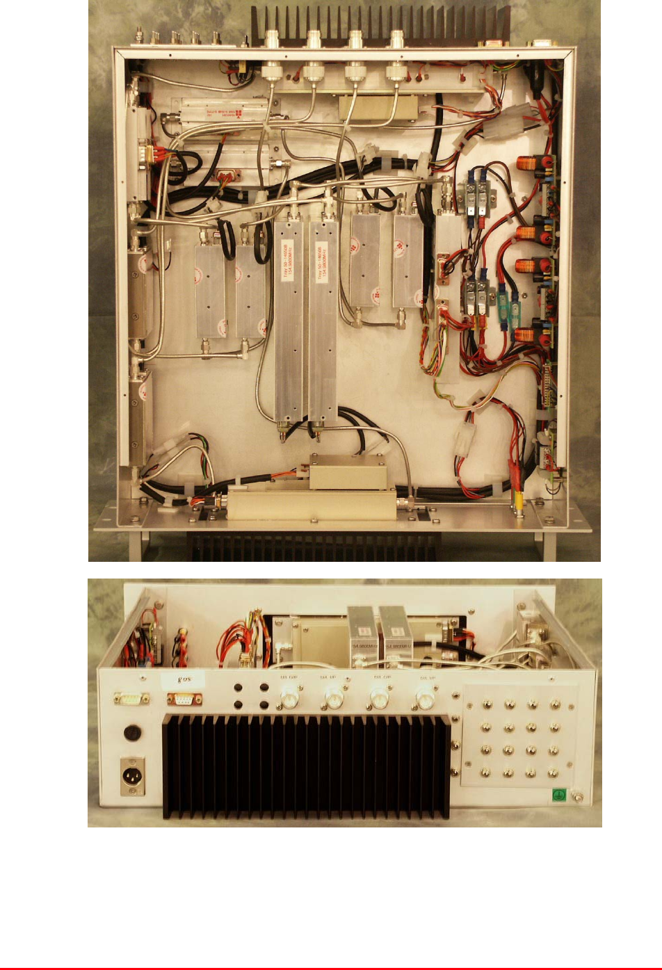
4.1.7.P VHF Duplex BDA Channel 1 Shelf Photographs
As all the duplex shelves are hardware similar, only this pair of duplex shelf photographs are shown.
Bronx Justice Centre Radio Repeaters
Handbook Number: 80-283501HBKM Page: 19 of 86
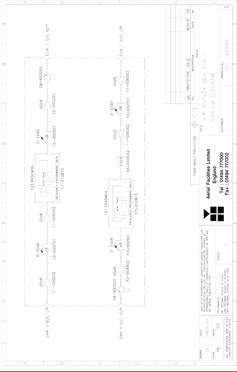
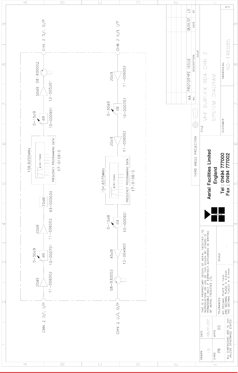
4.1.7.1Description
The two duplex bi-directional amplifier shelves receive a downlink signal from the input antenna,
amplify it to a level suitable for processing by a channel selective module and send the resultant 10W
power signal to its designated antenna.
The uplink path is very similar but in reverse with only a five Watt RF output power. Both paths
feature a ferrite isolator on the output to prevent damage to the power amplifier should any reflected
signals occur at their output antenna ports.
4.1.7.2Technical Specification
PARAMETER SPECIFICATION
Height: 3U
Width: 19" (482.6mm)
Shelf
dimensions: Depth: <450mm (excluding connectors & handles)
operational: -20°C to +60°C Temperature
range: storage: -40°C to +70°C
Weight: <10kg
153.956MHz (Ch. 1)
Downlink channel frequency: 158.925MHz (Ch. 2)
151.355MHz (Ch. 1)
Uplink channel frequency: 154.6575MHz (Ch. 2)
Shelf gain: 100dB (typical)
Impedance: 50ȍ
Humidity: 5 – 95% non-condensing
RF Connectors: N type female
Environmental protection: IP44
Case: Iridite NCP coating
Heatsinks: Black anodised
Handles: Silver anodised aluminium alloy
Finish
Fascia: Painted to RAL7035

Bronx Justice Centre Radio Repeaters
Handbook Number: 80-283501HBKM Page: 20 of 86
4.1.7.3Parts List
AFL Part # Part Description Qty.
08-930002 2 PORT ISOLATOR 150-300MHz SMA 2
10-000701 1/4W0-30dB SWITCHED ATTENUATOR 2
10-000901 SW. ATTENUATOR 0.25W 0-15dB 2
11-006002 LNA VHF 70-500MHz WITH RELAY 4
12-002201 3 STAGE AMPLIFIER ALARM BOARD 2
12-002220 3 STAGE ALARM PCB COVER 2
12-002826 ALARM BOARD ACRYLIC LENS 2
12-004902 POWER AMP VHF 5W CLASS AB 1
12-005201 P/A 10W VHF CLASS AB 1
13-001803 DUAL DC/DC CONVERTER 24V-12V 1A 2
13-001822 DC-DC CON 24V-5V/15V COVER 2
17-009725 EQUIP. MTG PLATE No.6 2
17-010810 VHF CH MOD 15kHz 8p +IFRX 10k Gated 2
19-000922KL 3U chassis kit 450 deep with led 1
20-001601 12V RELAY BOARD 1
80-008902 24V RELAY PCB ASSEMBLY **NO LED** 1
80-063920 HEATSINK 2U ASS140 (5W) 2
91-030002 N ADAPTOR PANEL FEMALE:FEMALE 4
91-500001 POWER PLG 3 PIN PNL.MOUNT NC-X 1
91-510003 3 PIN R.ANGLE FREE SOC.NC-X. 1
91-600001 'D'TYPE 9 WAY PLUG S/B TERM 1
91-600007 'D' 9 WAY BLACK SHELL 1
91-600014 'D' 9 WAY SOCKET S/B (NON FILTERED) 5
91-620001 'D' 25 WAY SOCKET S/B TERM 2
91-700017 ICD 15 WAY 0.1' CONNECTOR 3
93-000034 10dB IN LINE ATTENUATOR 1W SMA 1
96-110001 FUSE HOLDER 20 x 5mm6.3A 1
96-600002 INSULATING BOOT SMALL 1
96-600003 INSULATING BOOT D.C. 1
Bronx Justice Centre Radio Repeaters
Handbook Number: 80-283501HBKM Page: 21 of 86
4.1.7.4System Diagram, Drg. # 50-146584

Bronx Justice Centre Radio Repeaters
Handbook Number: 80-283501HBKM Page: 22 of 86
4.1.8 VHF Duplex BDA Channel 2 Shelf (50-146505)
4.1.8.P VHF Duplex BDA Channel 2 Shelf Photographs
The duplex shelves are all hardware similar – so only the channel 1 shelf photographs are shown
(see section 4.1.7.P)
4.1.8.1Description
See section 4.1.7.1
4.1.8.2Technical Specification
See section 4.1.7.2
4.1.8.3Parts List
AFL Part # Part Description Qty.
08-930002 2 PORT ISOLATOR 150-300MHz SMA 2
10-000701 1/4W0-30dB SWITCHED ATTENUATOR 2
10-000901 SW. ATTENUATOR 0.25W 0-15dB 4
11-006002 LNA VHF 70-500MHz WITH RELAY 4
12-002201 3 STAGE AMPLIFIER ALARM BOARD 2
12-002220 3 STAGE ALARM PCB COVER 2
12-002826 ALARM BOARD ACRYLIC LENS 2
12-004902 POWER AMP VHF 5W CLASS AB 1
12-005201 P/A 10W VHF CLASS AB 1
13-001803 DUAL DC/DC CONVERTER 24V-12V 1A 2
13-001822 DC-DC CON 24V-5V/15V COVER 2
17-009725 EQUIP. MTG PLATE No.6 2
17-010810 VHF CH MOD 15kHz 8p +IFRX 10k Gated 2
19-000922KL 3U chassis kit 450 deep with led 1
20-001601 12V RELAY BOARD 1
80-008902 24V RELAY PCB ASSEMBLY **NO LED** 1
80-063920 HEATSINK 2U ASS140 (5W) 2
91-030002 N ADAPTOR PANEL FEMALE:FEMALE 4
91-500001 POWER PLG 3 PIN PNL.MOUNT NC-X 1
91-510003 3 PIN R.ANGLE FREE SOC.NC-X. 1
91-600001 'D'TYPE 9 WAY PLUG S/B TERM 1
91-600007 'D' 9 WAY BLACK SHELL 1
91-600014 'D' 9 WAY SOCKET S/B (NON FILTERED) 4
91-620001 'D' 25 WAY SOCKET S/B TERM 2
91-700017 ICD 15 WAY 0.1' CONNECTOR 3
93-000034 10dB IN LINE ATTENUATOR 1W SMA 1
96-110001 FUSE HOLDER 20 x 5mm6.3A 1
96-600002 INSULATING BOOT SMALL 1
96-600003 INSULATING BOOT D.C. 1
Bronx Justice Centre Radio Repeaters
Handbook Number: 80-283501HBKM Page: 23 of 86
4.1.8.4System Diagram
Bronx Justice Centre Radio Repeaters
Handbook Number: 80-283501HBKM Page: 24 of 86
4.1.9 VHF Simplex BDA Channel 3A Shelf (50-146506)
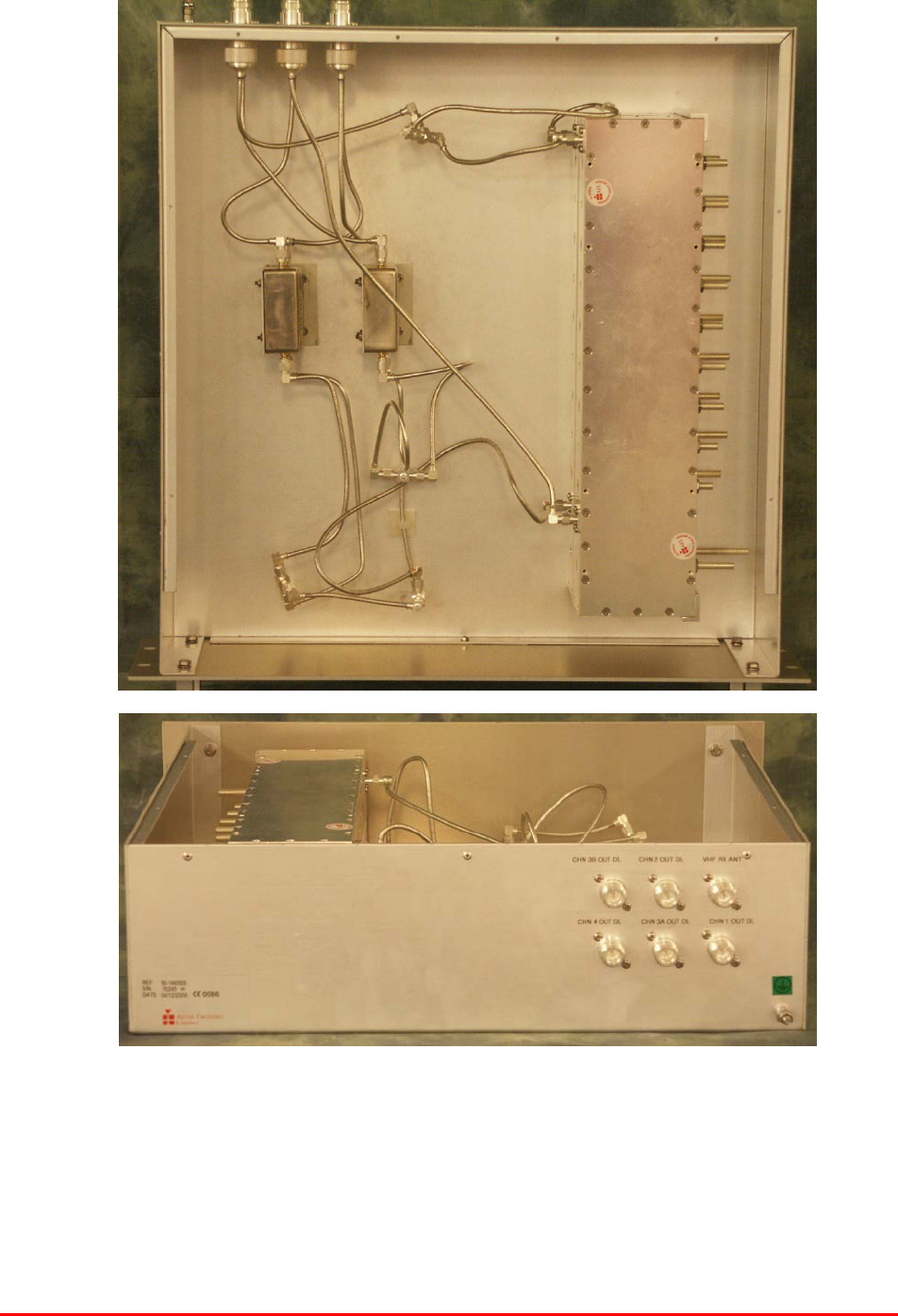
4.1.9.P VHF Simplex BDA Photographs
Bronx Justice Centre Radio Repeaters
Handbook Number: 80-283501HBKM Page: 25 of 86
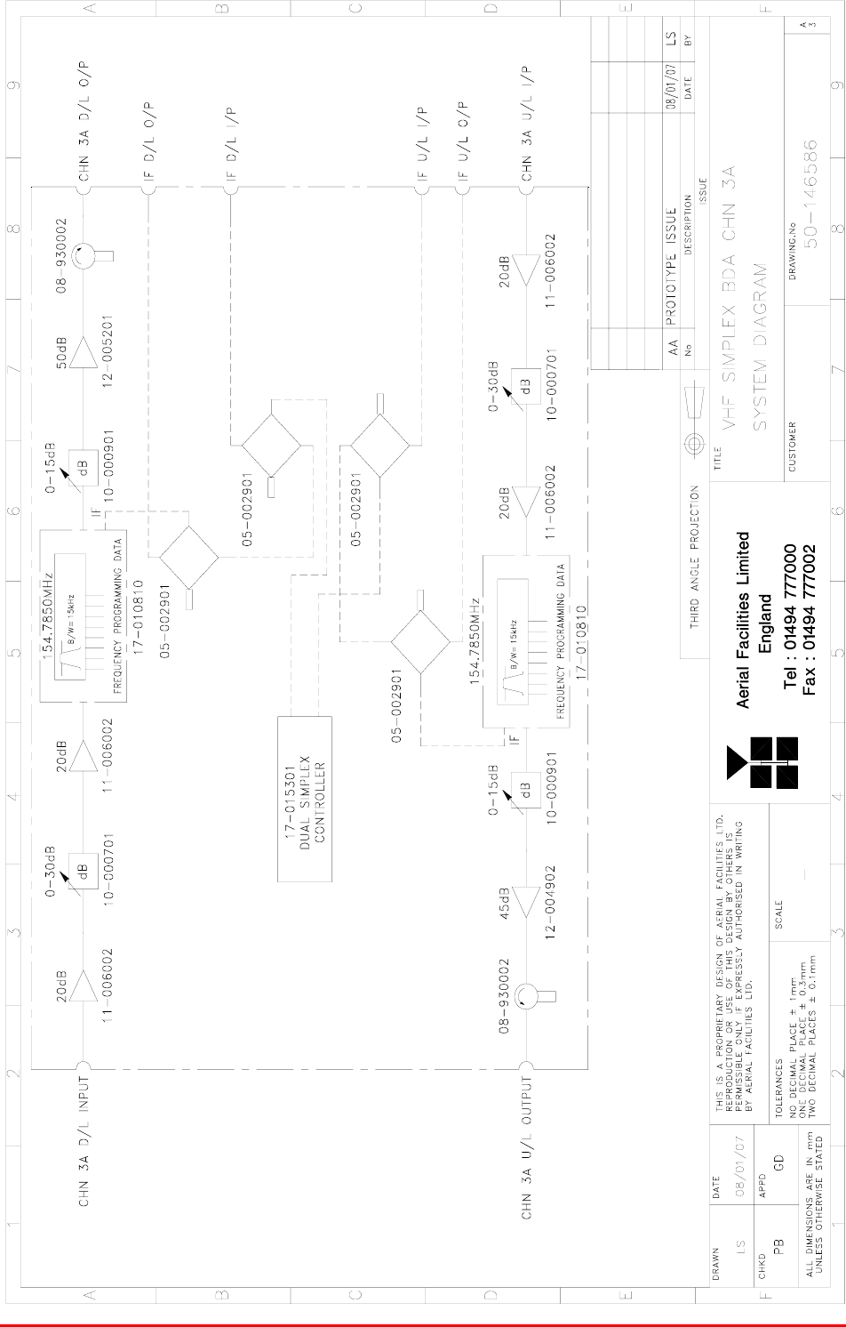
4.1.9.1Description
The simplex channel amplifier shelves (x3) receive their input signals from antennas and are
processed as follows:-
The Simplex controller module (17-015301) monitors the receiver output for a signal change and
activates the supply switching for either the uplink or down link path accordingly. In normal operation,
the low level Rx path is activated and the associated Tx path is switched off. When a signal is
detected by the downlink channel selective module, the Rx output goes low, which triggers the
controller logic PCB. The PCB mutes the power supply to the opposite path Rx LNA’s and switches
on the power to the output power stage. In order to prevent the power stage noise blocking the
opposite path’s low level receiver, the power amplifier is normally muted.
Both outputs are protected by ferrite isolators in a similar way to the duplex shelves.
All three simplex shelves are hardware similar so only channel 3A shelf is described.
4.1.9.2Technical Specification
PARAMETER SPECIFICATION
Height: 3U
Width: 19" (482.6mm)
Shelf
dimensions: Depth: <450mm (excluding connectors & handles)
operational: -20°C to +60°C Temperature
range: storage: -40°C to +70°C
Weight: <10kg
154.785MHz (Ch. 3A)
154.755MHz (Ch. 3B)
Channel frequencies:
154.980MHz (Ch. 4)
Shelf gain: 100dB (typical)
Impedance: 50ȍ
Humidity: 5 – 95% non-condensing
RF Connectors: N type female
Environmental protection: IP44
Case: Iridite NCP coating
Heatsinks: Black anodised
Handles: Silver anodised aluminium alloy
Finish
Fascia: Painted to RAL7035
Bronx Justice Centre Radio Repeaters
Handbook Number: 80-283501HBKM Page: 26 of 86
4.1.9.3System Diagram, Drg. # 50-146586

Bronx Justice Centre Radio Repeaters
Handbook Number: 80-283501HBKM Page: 27 of 86
4.1.9.4Parts List
AFL Part # Part Description Qty.
05-002901 3dB BROADBAND SPLITTER SMA 1WATT 4
08-930002 2 PORT ISOLATOR 150-300MHz SMA 2
10-000701 1/4W0-30dB SWITCHED ATTENUATOR 2
10-000723 2xSWITCHED ATTENUATOR FIXING PLATE 2
10-000901 SW. ATTENUATOR 0.25W 0-15dB 2
11-006002 LNA VHF 70-500MHz WITH RELAY 4
12-002201 3 STAGE AMPLIFIER ALARM BOARD 2
12-002220 3 STAGE ALARM PCB COVER 2
12-002826 ALARM BOARD ACRYLIC LENS 2
12-004902 POWER AMP VHF 5W CLASS AB 1
12-005201 P/A 10W VHF CLASS AB 1
13-001803 DUAL DC/DC CONVERTER 24V-12V 1A 2
13-001822 DC-DC CON 24V-5V/15V COVER 2
17-010810 VHF CH MOD 15kHz 8p +IFRX 10k Gated 2
17-015301 DUAL SIMPLEX CONTROLLER 1
19-000922KL 3U chassis kit 450 deep with led 1
20-001602 24V RELAY BOARD 2
80-008902 24V RELAY PCB ASSEMBLY **NO LED** 1
80-063920 HEATSINK 2U ASS140 (5W) 2
91-030002 N ADAPTOR PANEL FEMALE:FEMALE 4
91-130005 SMA BULKHEAD ADAPTOR F/F 4
91-500001 POWER PLG 3 PIN PNL.MOUNT NC-X 1
91-510003 3 PIN R.ANGLE FREE SOC.NC-X. 1
91-600001 'D'TYPE 9 WAY PLUG S/B TERM 1
91-600014 'D' 9 WAY SOCKET S/B (NON FILTERED) 5
91-620001 'D' 25 WAY SOCKET S/B TERM 2
91-620005 'D' 25 WAY PLUG S/B TERM 1
91-700017 ICD 15 WAY 0.1' CONNECTOR 2
93-520015 10K PANEL/PCB MTG POT 2
93-540035 1K3 0.25W 1% RES MRS25 M:F 2
96-110001 FUSE HOLDER 20 x 5mm 6.3A 1
96-600002 INSULATING BOOT SMALL 1
96-600003 INSULATING BOOT D.C. 1
96-700017 LED AMBER 5mm SEALED IP66 2

Bronx Justice Centre Radio Repeaters
Handbook Number: 80-283501HBKM Page: 28 of 86
4.1.10 VHF Simplex BDA Channel 3B Shelf (50-146507)
4.1.10.P VHF Simplex BDA Channel 3B Photographs
See section 4.1.9.P
4.1.10.1 Description
See section 4.1.9.1
4.1.10.2 Technical Specification
See section 4.1.9.2

Bronx Justice Centre Radio Repeaters
Handbook Number: 80-283501HBKM Page: 29 of 86
4.1.10.3 System Diagram, Drg. # 50-146587

Bronx Justice Centre Radio Repeaters
Handbook Number: 80-283501HBKM Page: 30 of 86
4.1.10.4 Parts List
AFL Part # Part Description Qty.
05-002901 3dB BROADBAND SPLITTER SMA 1WATT 4
08-930002 2 PORT ISOLATOR 150-300MHz SMA 2
10-000701 1/4W0-30dB SWITCHED ATTENUATOR 2
10-000723 2 x SWITCHED ATTENUATOR FIXING PLATE 2
10-000901 SW. ATTENUATOR 0.25W 0-15dB 2
11-006002 LNA VHF 70-500MHz WITH RELAY 4
12-002201 3 STAGE AMPLIFIER ALARM BOARD 2
12-002220 3 STAGE ALARM PCB COVER 2
12-002826 ALARM BOARD ACRYLIC LENS 2
12-004902 POWER AMP VHF 5W CLASS AB 1
12-005201 P/A 10W VHF CLASS AB 1
13-001803 DUAL DC/DC CONVERTER 24V-12V 1A 2
17-010810 VHF CH MOD 15kHz 8p +IFRX 10k Gated 2
17-015301 DUAL SIMPLEX CONTROLLER 1
19-000922KL 3U chassis kit 450 deep with led 1
20-001602 24V RELAY BOARD 2
80-008902 24V RELAY PCB ASSEMBLY **NO LED** 1
80-063920 HEATSINK 2U ASS140 (5W) 2
91-030002 N ADAPTOR PANEL FEMALE:FEMALE 4
91-130005 SMA BULKHEAD ADAPTOR F/F 4
91-500001 POWER PLG 3 PIN PNL.MOUNT NC-X 1
91-510003 3 PIN R.ANGLE FREE SOC.NC-X. 1
91-600001 'D'TYPE 9 WAY PLUG S/B TERM 1
91-600014 'D' 9 WAY SOCKET S/B (NON FILTERED) 5
91-620001 'D' 25 WAY SOCKET S/B TERM 2
91-620005 'D' 25 WAY PLUG S/B TERM 1
91-700017 ICD 15 WAY 0.1' CONNECTOR 2
93-520015 10K PANEL/PCB MTG POT 2
93-540035 1K3 0.25W 1% RES MRS25 M:F 2
96-110001 FUSE HOLDER 20 x 5mm6.3A 1
96-600002 INSULATING BOOT SMALL 1
96-600003 INSULATING BOOT D.C. 1
96-700017 LED AMBER 5mm SEALED IP66 2

Bronx Justice Centre Radio Repeaters
Handbook Number: 80-283501HBKM Page: 31 of 86
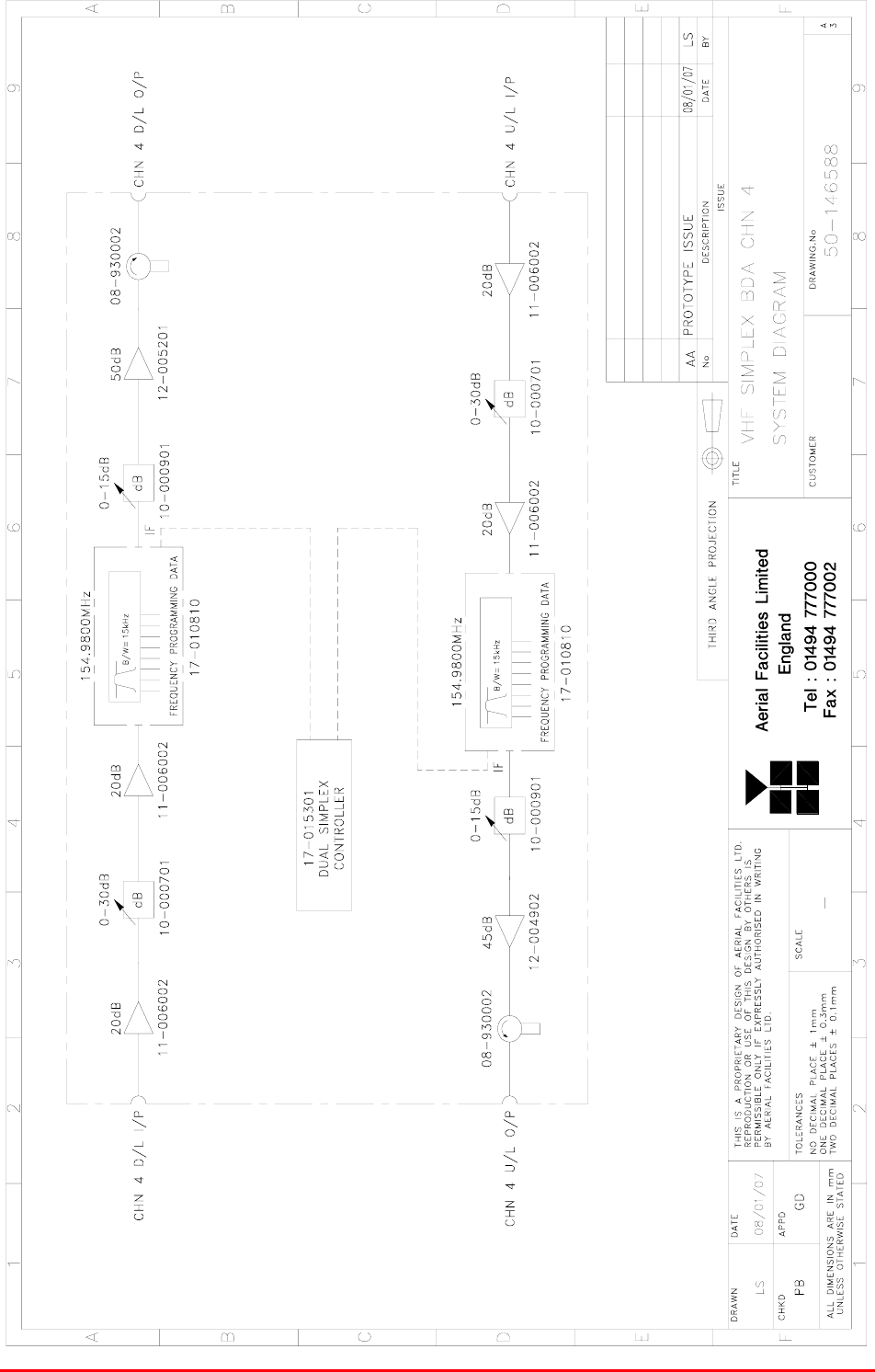
4.1.11 VHF Simplex BDA Channel 4 Shelf (50-146508)
4.1.11.P VHF Simplex BDA Channel 4 Shelf Photographs
See section 4.1.9.P
4.1.11.1 Description
See section 4.1.9.1
4.1.11.2 Technical Specification
See section 4.1.9.2
Bronx Justice Centre Radio Repeaters
Handbook Number: 80-283501HBKM Page: 32 of 86
4.1.11.3 System Diagram, Drg. # 50-146588

Bronx Justice Centre Radio Repeaters
Handbook Number: 80-283501HBKM Page: 33 of 86
4.1.11.4 Parts List
AFL Part # Part Description Qty.
08-930002 2 PORT ISOLATOR 150-300MHz SMA 2
10-000701 1/4W0-30dB SWITCHED ATTENUATOR 2
10-000723 2xSWITCHED ATTENUATOR FIXING PLATE 2
10-000901 SW. ATTENUATOR 0.25W 0-15DB 2
11-006002 LNA VHF 70-500MHz WITH RELAY 4
12-002201 3 STAGE AMPLIFIER ALARM BOARD 2
12-002220 3 STAGE ALARM PCB COVER 2
12-002826 ALARM BOARD ACRYLIC LENS 2
12-004902 POWER AMP VHF 5W CLASS AB 1
12-005201 P/A 10W VHF CLASS AB 1
13-001803 DUAL DC/DC CONVERTER 24V-12V 1A 2
13-001822 DC-DC CON 24V-5V/15V COVER 2
17-010810 VHF CH MOD 15kHz 8p +IFRX 10k Gated 2
17-015301 DUAL SIMPLEX CONTROLLER 1
19-000922KL 3U chassis kit 450 deep with led 1
20-001602 24V RELAY BOARD 2
80-008902 24V RELAY PCB ASSEMBLY **NO LED** 1
80-063920 HEATSINK 2U ASS140 (5W) 2
91-030002 N ADAPTOR PANEL FEMALE:FEMALE 4
91-500001 POWER PLG 3 PIN PNL.MOUNT NC-X 1
91-510003 3 PIN R.ANGLE FREE SOC.NC-X. 1
91-600001 'D'TYPE 9 WAY PLUG S/B TERM 1
91-600014 'D' 9 WAY SOCKET S/B (NON FILTERED) 5
91-620001 'D' 25 WAY SOCKET S/B TERM 2
91-620005 'D' 25 WAY PLUG S/B TERM 1
91-700017 ICD 15 WAY 0.1' CONNECTOR 2
93-520015 10K PANEL/PCB MTG POT 2
93-540035 1K3 0.25W 1% RES MRS25 M:F 2
96-110001 FUSE HOLDER 20 x 5mm6.3A 1
96-600002 INSULATING BOOT SMALL 1
96-600003 INSULATING BOOT D.C. 1
96-700017 LED AMBER 5mm SEALED IP66 2
Bronx Justice Centre Radio Repeaters
Handbook Number: 80-283501HBKM Page: 34 of 86
4.1.12 Downlink I/P Splitter (50-146509)
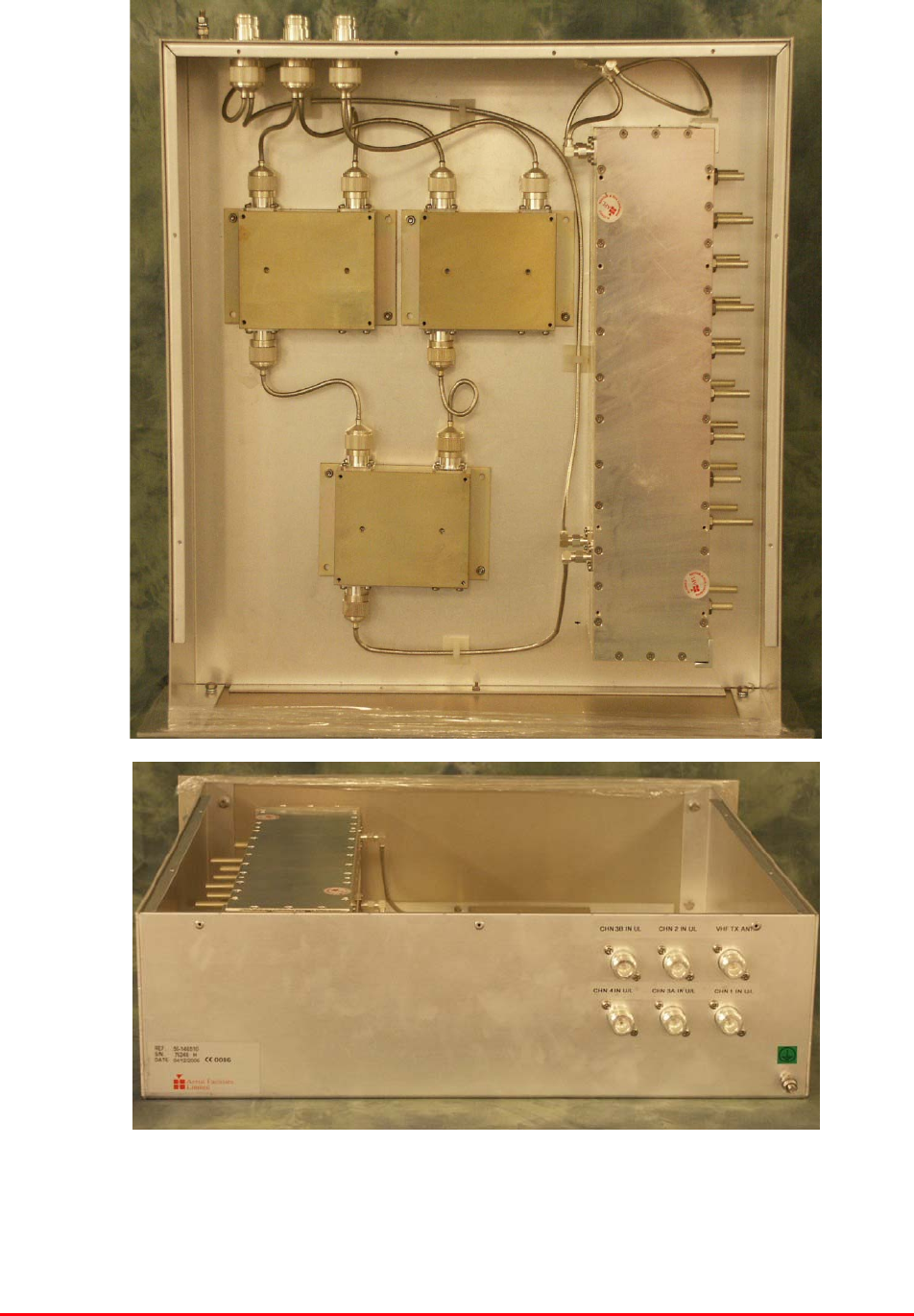
4.1.12.P Downlink Input Splitter Photographs
Bronx Justice Centre Radio Repeaters
Handbook Number: 80-283501HBKM Page: 35 of 86
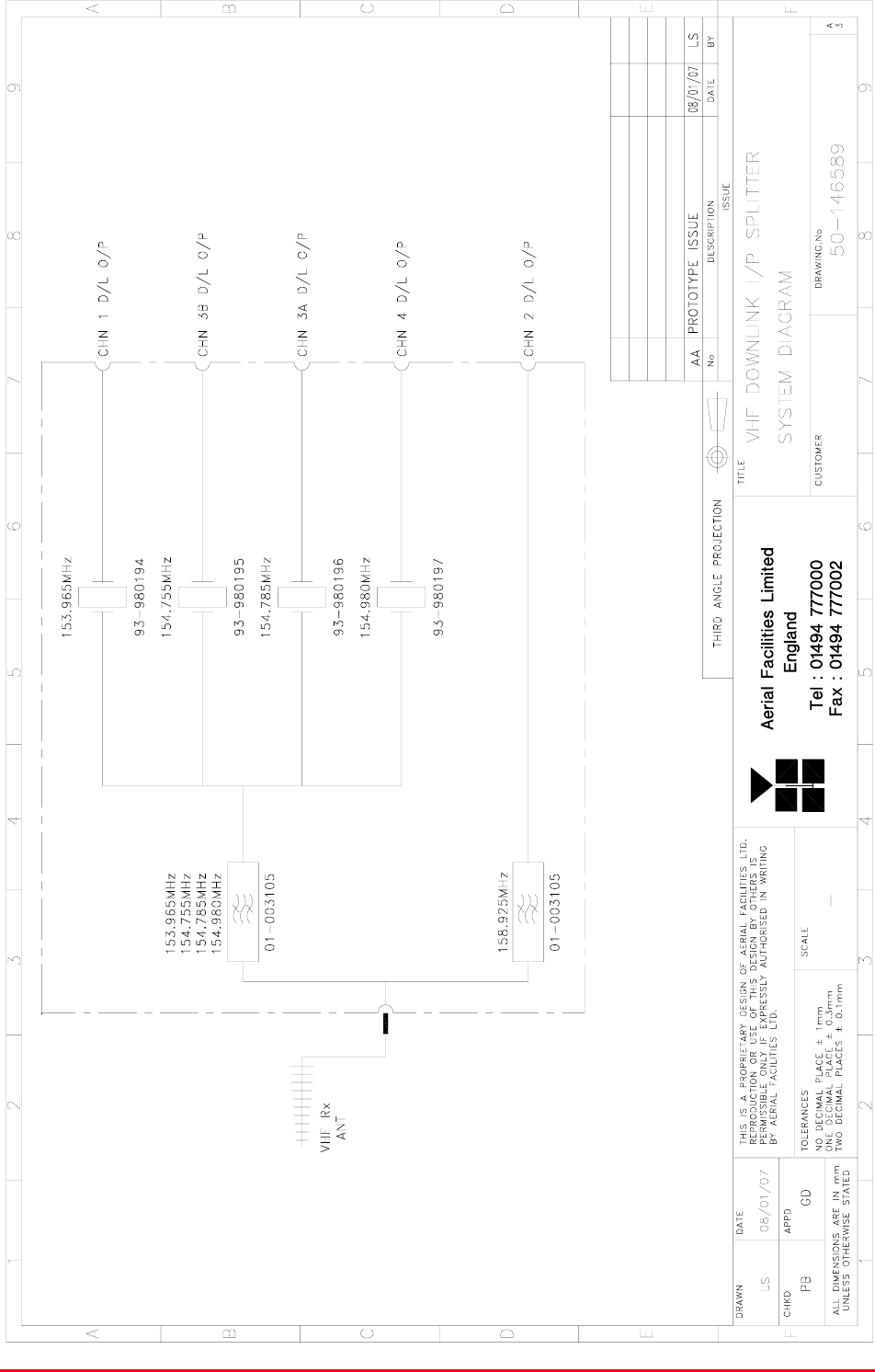
4.1.12.1 Description
The input splitter shelf receives VHF signals from the off-air antenna and passes them through two
bandpass filters one of which is tuned to channel 2 and the other tuned to include channels 1, 3A, 3B
&4. The output of the filter tuned for channel 2 goes directly to the channel 2 cell enhancer input but
the other path is split by four crystal filters, the outputs of which go separately to the inputs of the
respective cell enhancer inputs. This is a passive shelf with no connection to any DC source and no
alarms.
4.1.12.2 Technical Specification
PARAMETER SPECIFICATION
Height: 3U
Width: 19" (482.6mm)
Shelf
dimensions: Depth: <450mm (excluding connectors & handles)
operational: -20°C to +60°C Temperature
range: storage: -40°C to +70°C
Weight: <10kg
Frequency ranges passed: 153.965 to 154.980 & 158.925MHz
Impedance: 50ȍ
Humidity: 5 – 95% non-condensing
RF Connectors: N type female
Environmental protection: IP44
Case: Iridite NCP coat
Heatsinks: None
Handles: Silver anodised aluminium alloy
Finish
Fascia Painted to RAL7035
4.1.12.3 Parts List
AFL Part # Part Description Qty.
01-003105 SD NOTCH FILT.N 6 SECT.VHF H/B SMA 2
19-000922K 3U CHASSIS KIT (450mm deep) 1
91-030002 N ADAPTOR PANEL FEMALE:FEMALE 6
91-130001 SMA ADAPT 'T' ALL FEMALE 3 GHz 4
93-980194 153.965MHz CRYSTAL FILT FAN4M52500 1
93-980195 154.755MHz CRYSTAL FILT FAN4M52500 1
93-980196 154.785MHz CRYSTAL FILT FAN4M52500 1
93-980197 154.980MHz CRYSTAL FILT FAN4M52500 1
Bronx Justice Centre Radio Repeaters
Handbook Number: 80-283501HBKM Page: 36 of 86
4.1.12.4 System Diagram, Drg. # 50-146589
Bronx Justice Centre Radio Repeaters
Handbook Number: 80-283501HBKM Page: 37 of 86
4.1.13 Downlink O/P Combiner (50-146510)
4.1.13.P Downlink O/P Combiner Photographs
Bronx Justice Centre Radio Repeaters
Handbook Number: 80-283501HBKM Page: 38 of 86
4.1.13.1 Description
The passive downlink output combiner shelf receives the five separate VHF cell enhancer output
signals and couples them together through hybrid and bandpass filters into three identical paths.
This shelf has no power source and no alarms.
4.1.13.2 Technical Specification
PARAMETER SPECIFICATION
Height: 3U
Width: 19" (482.6mm)
Shelf
dimensions: Depth: <450mm (excluding connectors & handles)
operational: -20°C to +60°C Temperature
range: storage: -40°C to +70°C
Weight: <10kg
Frequency ranges passed: 153.965 to 154.980 & 158.925MHz
Impedance: 50ȍ
Humidity: 5 – 95% non-condensing
RF Connectors: N type female
Environmental protection: IP44
Case: Iridite NCP coat
Heatsinks: None
Handles: Silver anodised aluminium alloy
Finish
Fascia Painted to RAL7035
4.1.13.3 Parts List
AFL Part # Part Description Qty.
01-003105 SD NOTCH FILT.N 6 SECT.VHF H/B SMA 2
05-000103 TX HYBRID COUPLER 3 PORT NO HTSINK 3
19-000922K 3U CHASSIS KIT (450mm deep) 1
91-030002 N ADAPTOR PANEL FEMALE:FEMALE 6
91-130001 SMA ADAPT 'T' ALL FEMALE 3 GHz 1
Bronx Justice Centre Radio Repeaters
Handbook Number: 80-283501HBKM Page: 39 of 86
4.1.13.4 System Diagram
Bronx Justice Centre Radio Repeaters
Handbook Number: 80-283501HBKM Page: 40 of 86
4.1.14 VHF/UHF 24V Power Supply Shelf (50-146512)
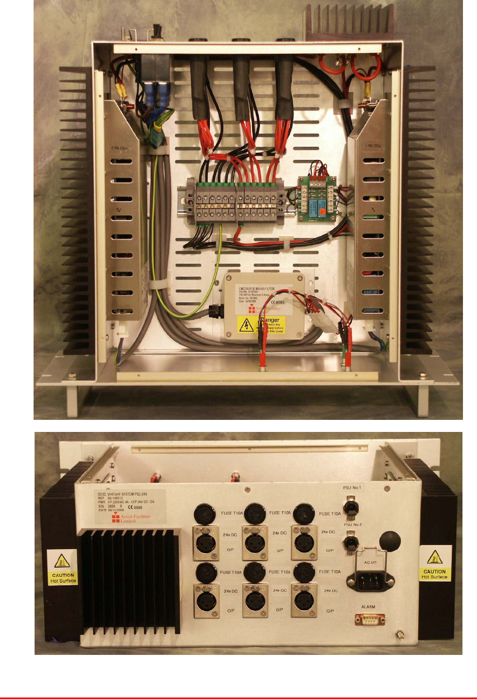
4.1.14.P VHF/UHF Power supply Shelf Photographs
Bronx Justice Centre Radio Repeaters
Handbook Number: 80-283501HBKM Page: 41 of 86
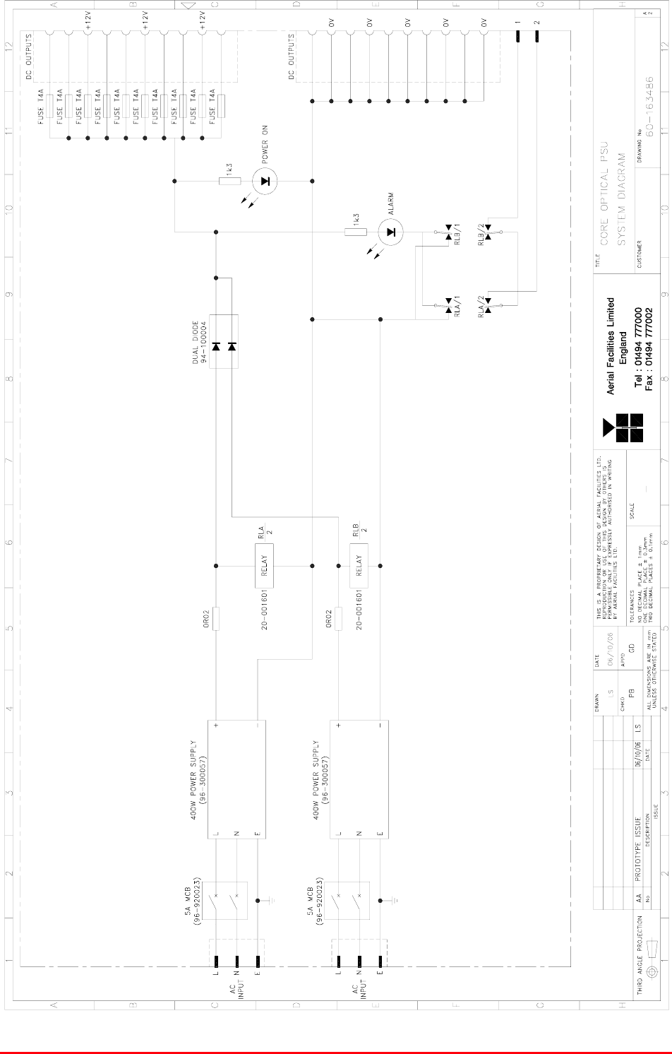
4.1.14.1 VHF/UHF PSU Shelf Description
The power supply shelf consists of two, 400Watt 24V DC O.E.M modules which are commonly
supplied from the mains but separately switched. The DC outputs are separately monitored and this
data becomes half of the alarm data for the shelf (the two monitor loops are summed to form a single
alarm relay contact pair). A pair of low-loss power diodes combine the outputs from the PSU modules
in a redundant configuration such that if either module fails, the other supply would still be active but
the faulty supply’s DC LED on the front panel would be extinguished and the alarm loop would be
broken.
4.1.14.2 VHF/UHF PSU Shelf Technical Specification
PARAMETER SPECIFICATION
Height: 5U
Width: 19" (482.6mm)
Shelf
dimensions: Depth: <450mm (excluding connectors & handles)
operational: -20°C to +60°C Temperature
range: storage: -40°C to +70°C
Weight: <10kg
Humidity: 5 – 95% non-condensing
DC Output connectors: 6 x XLR female
DC Output Voltage: 24V DC (x 6)
24V DC O/P fuse rating: 10A (x 6)
Environmental protection: IP44
Alarms: PSU1 & 2 (‘D’ connector pins 1 & 2)
Case: Iridite NCP coat
Heatsinks: Black anodised aluminium
Handles: Silver anodised aluminium alloy
Finish
Fascia Painted to RAL7035

Bronx Justice Centre Radio Repeaters
Handbook Number: 80-283501HBKM Page: 42 of 86
4.1.14.3 VHF/UHF PSU Shelf Parts List
AFL Part # Part Description Qty.
13-003301 MAINS FILTER 8AMP ASSEMBLY 1
16-000222 DUPLEXER/CELL ENHANCER CASE RAIL 4
20-001601 12V RELAY BOARD 1
80-008920 DUAL PSU HEATSINK 2
80-008921 DUAL PSU CASE 1
80-008922 DUAL PSU LID 1
80-008925 DUAL PSU FRONT PANEL 1
91-500025 3 PIN RIGHT ANGLE FREE PLUG NC-X 6
91-510004 3 PIN PNL.MOUNT SOCKET NC-X 6
91-510035 3 WAY MATE N LOK PLUG HOUSING 2
91-520001 PWR MAINS INL FIXED/SOLD.TERMS 1
91-520005 MAINS LEAD 1
91-520010 MAINS RETAINING CLIP 1
91-520032 MATE N LOK SOCKET CONTACT 20/14 AWG 6
91-600015 'D' 9 WAY PLUG S/B (NON FILTERED) 1
91-800014 3 WAY TERMINAL BLOCK 1
91-800015 TRIPLE DECK TERMINAL BLOCK 8
91-800016 TRIPLE DECK TERMINAL JUMPER 6
91-800017 TRIPLE DECK TERMINAL END 1
91-800028 DIN RAIL END-STOP 2
91-800031 SYMETRIC 35 x 7.5mm DIN RAIL 0
92-900014 DIN RAIL (TOP HAT) EARTH CLAMP M5 1
93-510077 0R02 50W RESISTOR ALUMINIUM CLAD 2
94-100004 STPS12045TV 60A DUAL DIODE 1
95-100007 TX.FERRITE ISOL.HT.SINK B/ANOD 3
96-110034 FUSE HOLDER 16-30A, 32mm BODY ONLY 6
96-110064 FUSE HOLDER 16-30A, 32mm INSERT 6
96-300054 24V 17A PSU 400W (XP BCC) 2
96-600001 INSULATING BOOT LARGE 1
96-700034 LED RED 5mm IP67 INTEGRAL RES. 24V 1
96-700035 LED GREEN 5mm IP67 INTEGRAL RES 24V 2
96-920023 5A CIRCUIT BREAKER (ETA) 2
97-400002 HANDLE TYPE H6803 4U.[ALLOY] 2
Bronx Justice Centre Radio Repeaters
Handbook Number: 80-283501HBKM Page: 43 of 86
4.1.14.4 VHF/UHF PSU Shelf System Diagram, (needs new drawing)