PBE Europe as Axell Wireless 50-1465SERIES 50-146501 VHF Channelised Air Interface User Manual 50 146501 50 146601 50 146701HBKM
Axell Wireless 50-146501 VHF Channelised Air Interface 50 146501 50 146601 50 146701HBKM
Contents
- 1. User Manual 1 of 2
- 2. User Manual 2 of 2
User Manual 2 of 2
Bronx Justice Centre Radio Repeaters
Handbook Number: 80-283501HBKM Page: 44 of 86
4.2 UHF Channel Selective Cell Enhancer Rack (50-146601)
4.2.1 Description
The UHF cell enhancer in this system is a six channel, duplex only, two-way radio repeater rack with
automatic gain control of both up and downlink paths. A dedicated power supply provides all the DC
needed by the whole rack, driven from the local mains supplies (identical with PSU in VHF cell
enhancer rack). Alarms are provided from each active device and all are ‘looped’ to form a normally
closed fail-safe alarm (locally for each shelf and globally for the whole enhancer). This loop alarm is
easily configured to join any other similarly wired system.
4.2.2 Electrical Specification
PARAMETER SPECIFICATION
453.7500MHz
465.0375MHz
471.2625MHz
479.8375MHz
481.0375MHz
485.6375MHz
UHF downlink
458.7500MHz
460.0375MHz
470.7125MHz
474.2625MHz
476.8375MHz
UHF frequencies:
484.0375MHz
UHF uplink
Gain Adjustment: 0 - 30dB (in 2dB steps)
Gain Adjustment: 0 – 15dB (in 1dB step)
Uplink Power: 5 Carriers @ +24dBm
Downlink Power: 5 Carriers @ +27dBm
AGC: Fitted in all channel selective modules
In-Band Spurious: Better than –13dBm (measured with
30KHz BW with max gain setting)
Noise Figure: <6dB (@ maximum gain)
VSWR: better than 1.5:1
Impedance: 50ȍ
1 Amplifiers Alarms Fitted:
(volt-free contacts/TTL) 2 PSU
4.2.3 Mechanical Specification
PARAMETER SPECIFICATION
Height: 43U Standard Eldon Vented Rack
Width: 19" (482.6mm)
Rack
Depth: 600mm
Height: See shelves parts lists
Width: 19" (482.6mm)
Shelves:
Depth: <450mm(excluding heatsinks, connectors,
handles and feet)
operational: -20°C to +60°C Temperature
range: storage: -40°C to +70°C
Weight: >100kg
Humidity: 5 – 95% non-condensing
RF Connectors: N type female
Environmental protection: IP44
Supply cable: Dedicated PSU shelf supply cable

Bronx Justice Centre Radio Repeaters
Handbook Number: 80-283501HBKM Page: 45 of 86
4.2.4 Parts List
AFL Part Nǀ.Part Description Qty.
50-146512 VHF/UHF SYSTEM PSU 24v 1
50-146602 UHF DOWNLINK COMBINER 1
50-146603 UHF UPLINK SPLITTER 1
50-146604 UHF DUPLEX BDA CHN1 1
50-146605 UHF DUPLEX BDA CHN2 1
50-146606 UHF DUPLEX BDA CHN3 1
50-146607 UHF DUPLEX BDA CHN4 1
50-146608 UHF DUPLEX BDA CHN5 1
50-146609 UHF UPLINK COMBINER 1
50-146610 UHF DOWNLINK SPLITTER 1
50-146612 UHF DUPLEX BDA CHN6 1
80-054020 600mm DEEP SUPPORT BRACKET 22
80-063654 1U BLANKING PANEL (BS) RAL 7035 4
90-100011 IEC MAINS LEAD '6 AMP' for USA 1
91-000002 N PLUG RG223:U 58
91-030002 N ADAPTOR PANEL FEMALE:FEMALE 4
97-500175 ELDON 43U 600 x 600 RACK (VENTED LID) 1
99-000082 PALLET 900 x 900 x 7ply FOR RACKS 1
Bronx Justice Centre Radio Repeaters
Handbook Number: 80-283501HBKM Page: 46 of 86
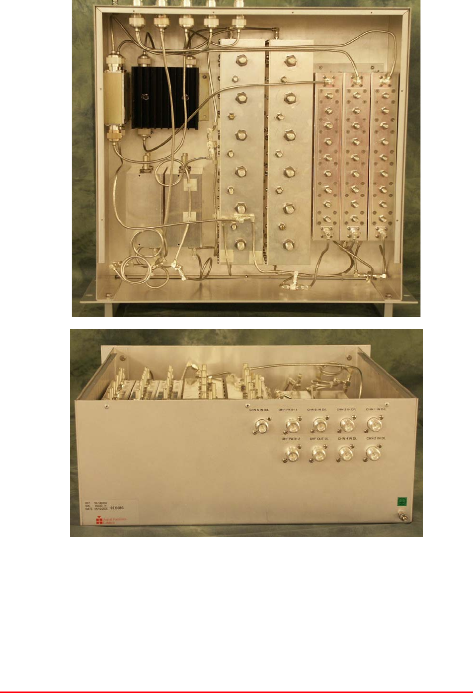
4.2.5 Downlink Combiner Shelf (50-146602)
4.2.5.P Downlink Combiner Photographs
Bronx Justice Centre Radio Repeaters
Handbook Number: 80-283501HBKM Page: 47 of 86
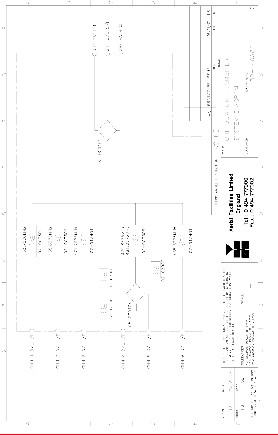
4.2.5.1Description
The UHF downlink combiner shelf receives signals from the outputs of the six BDA shelves and
combines them using a series of bandpass, notch filters and hybrid couplers. The two UHF outputs
then directly drive the leaky feeder antennas. This is a passive only shelf and has no need of a power
source or alarms.
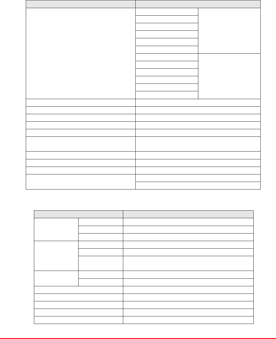
4.2.5.2Technical Specification
PARAMETER SPECIFICATION
DC power consumption: None
Chassis height: 4U
IP protection: IP44
Relative humidity range: 5-95%
Impedance: 50ȍ
Alarms: None
operation: -10C to +60C
Temperature Range: storage: -30C to +70C
Case: Alocrom 1200/Iridite NCP
Heatsinks: None
Fascia: Painted to RAL7035
Finish:
Handles: Silver anodise
4.2.5.3Parts List
AFL Part Nǀ.Part Description Qty.
02-007309 SDF C/L5P VAR.BW TOP SMA 50mm POST 3
02-013401 6P CL FLTR(0.5 min BW) LARGE SMA ASSY 2
02-020001 UHF 2 LN NOTCH FILTER SMA 3
05-000101 TRANSMITTER HYBD COUPL.4 PORT 1
05-000104 TRANS.HYBRD.COUPL.3 PORT 50W INT.L 1
19-001022K 4U CHASSIS KIT (450mm deep) 1
91-030002 N ADAPTOR PANEL FEMALE:FEMALE 9
91-130001 SMA ADAPT 'T' ALL FEMALE 3 GHz 5
Bronx Justice Centre Radio Repeaters
Handbook Number: 80-283501HBKM Page: 48 of 86
4.2.5.4System Diagram, Drg. # 50-146682
Bronx Justice Centre Radio Repeaters
Handbook Number: 80-283501HBKM Page: 49 of 86
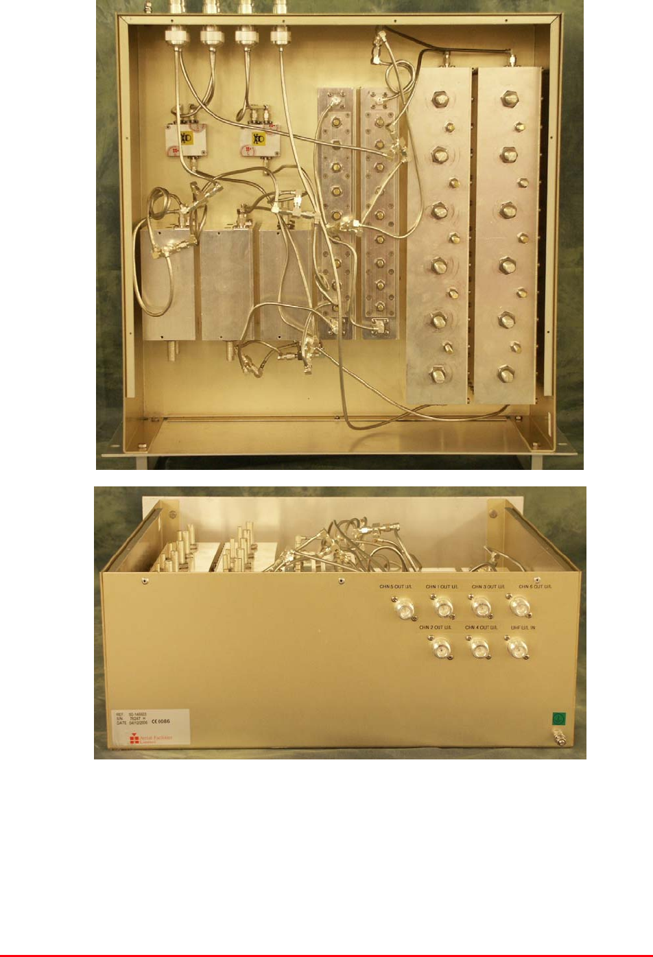
4.2.6 Uplink Splitter Shelf (60-146603)
4.2.6.P Uplink Splitter Shelf Photographs
Bronx Justice Centre Radio Repeaters
Handbook Number: 80-283501HBKM Page: 50 of 86
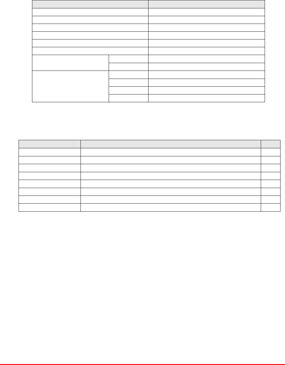
4.2.6.1Description
The UHF uplink splitter receives a single RF source (from the leaky feeder antenna(s) and directs it
through hybrid couplers, bandpass and notch filters to the inputs of the UHF uplink BDA shelves. This
is a passive only shelf and has no need of a power source or alarms.
4.2.6.2Technical Specification
PARAMETER SPECIFICATION
DC power consumption: None
Chassis height: 4U
IP protection: IP44
Relative humidity range: 5-95%
Impedance: 50ȍ
Alarms: None
operation: -10C to +60C
Temperature Range: storage: -30C to +70C
Case: Alocrom 1200/Iridite NCP
Heatsinks: None
Fascia: Painted to RAL7035
Finish:
Handles: Silver anodise
4.6.2.3Parts List
AFL Part Nǀ.Part Description Qty.
02-007302 SDF C/L5P VAR.BW TOP SMA 40 mm POST 1
02-007309 SDF C/L5P VAR.BW TOP SMA 50mm POST 1
02-013401 6P CL FLTR (0.5 min BW) LARGE SMA ASSY 2
02-020001 UHF 2 LN NOTCH FILTER SMA 3
05-002603 UHF 3DB SPLITTER SMA 2
19-001022K 4U CHASSIS KIT (450mm deep) 1
91-030002 N ADAPTOR PANEL FEMALE:FEMALE 7
91-130001 SMA ADAPT 'T' ALL FEMALE 3 GHz 3
Bronx Justice Centre Radio Repeaters
Handbook Number: 80-283501HBKM Page: 51 of 86
4.2.6.4System Diagram, Drg. # 50-146683
Bronx Justice Centre Radio Repeaters
Handbook Number: 80-283501HBKM Page: 52 of 86
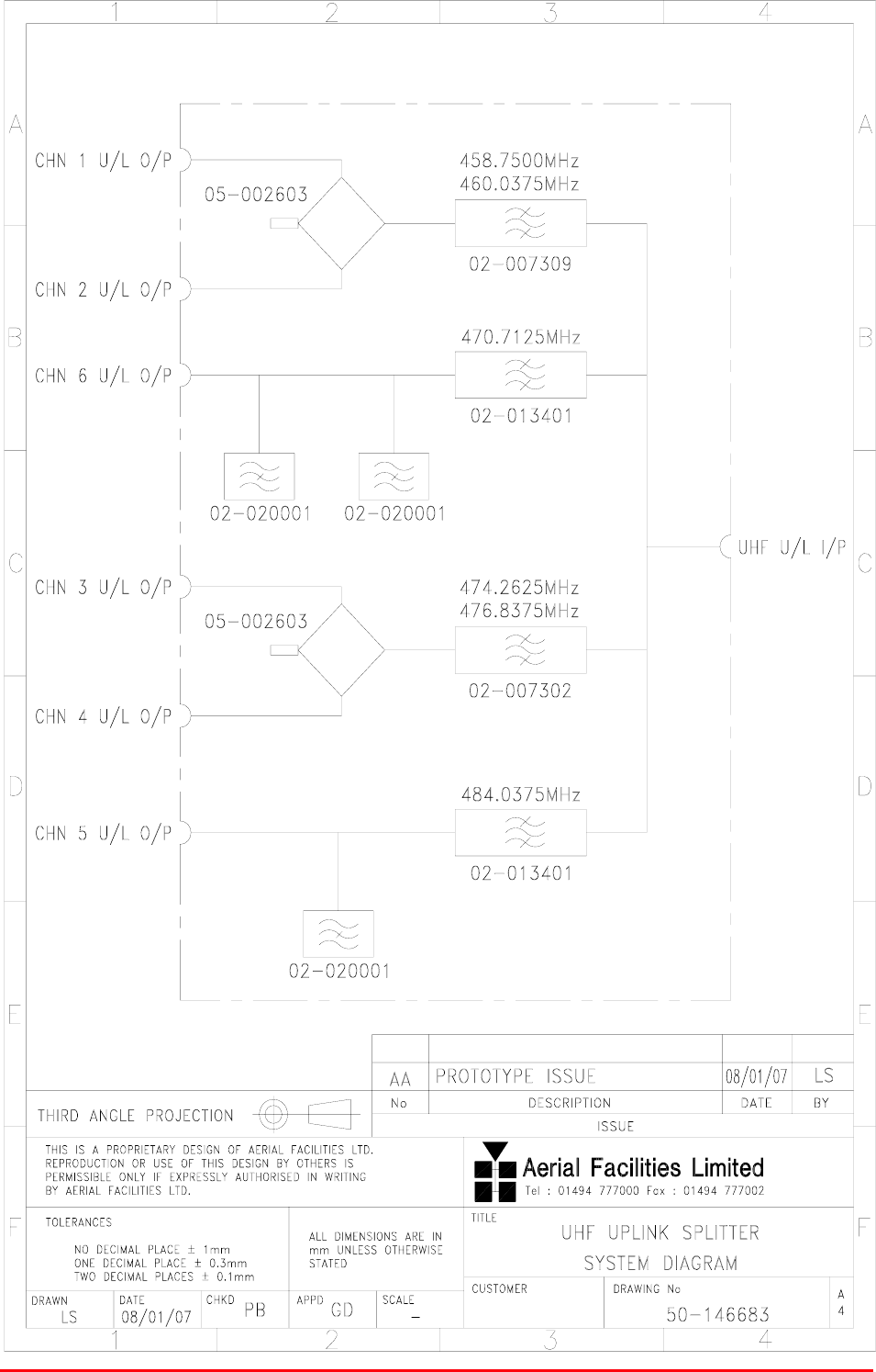
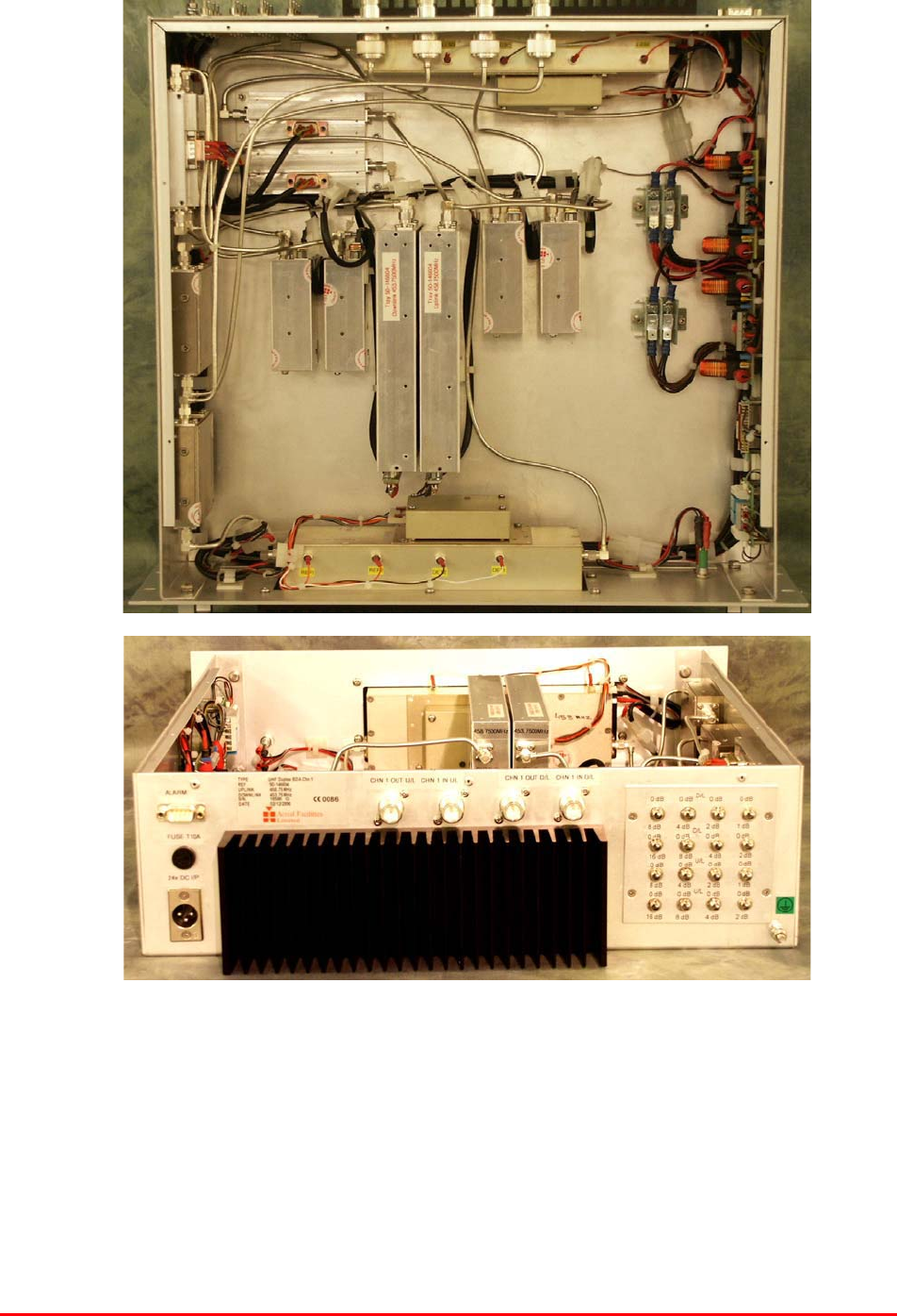
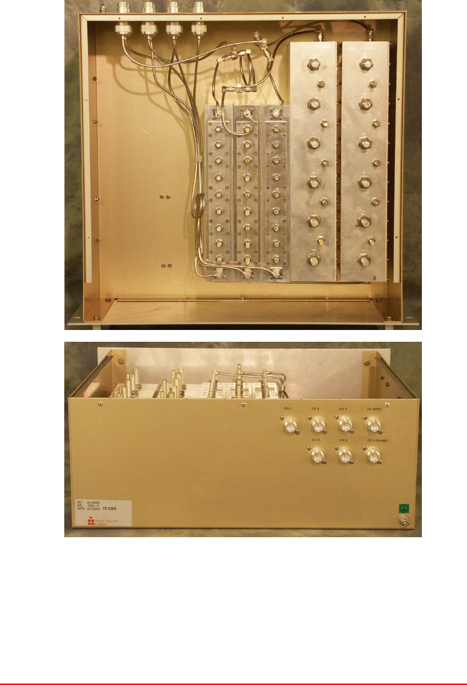
4.2.7 UHF Duplex Channel 1 BDA (50-146604)
4.2.7.P Duplex Shelf Photographs (hardware identical, only 1 shelf shown)
Bronx Justice Centre Radio Repeaters
Handbook Number: 80-283501HBKM Page: 53 of 86
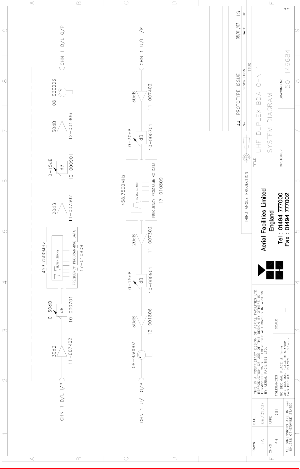
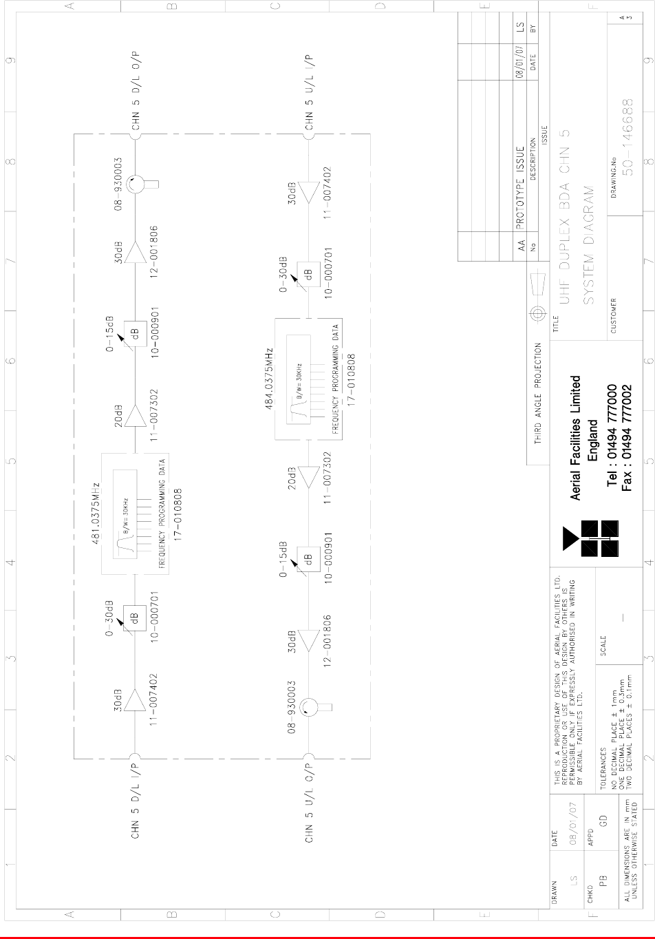
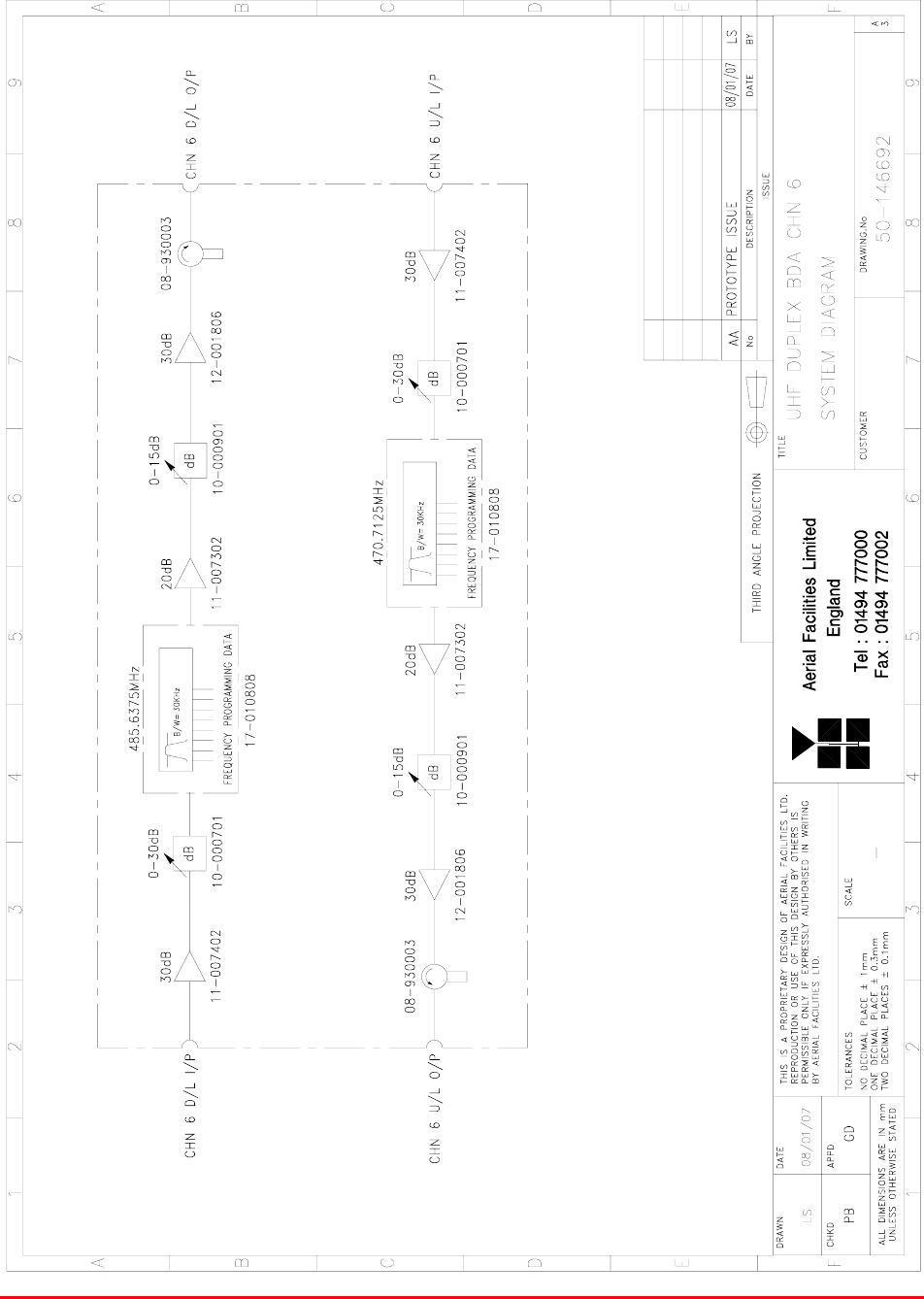
4.2.7.1Description
The BDA shelves amplify the UHF digital signals at specific frequencies, selected by the channel
control modules. They each have a gain of approximately 95dB and switched attenuators after the
input amplifier and at the output so that channels may be individually set up for the best signal levels
at the time of installation.
4.2.7.2Technical Specification
PARAMETER SPECIFICATION
453.750MHz (Ch. 1)
465.0375MHz (Ch. 2)
472.2675MHz (Ch. 3)
479.8375MHz (Ch. 4)
484.0375MHz (Ch. 5)
470.7125
UHF downlink
458.750MHz (Ch. 1)
460.0375MHz (Ch. 2)
471.2625MHz (Ch. 3)
476.8375MHz (Ch. 4)
481.0375MHz (Ch. 5)
UHF Frequencies:
485.6375MHz (Ch. 6)
UHF uplink
Bandwidth: 15kHz (up & downlink)
Height: 3U
Width: 19" (482.6mm)
Shelves
Depth: <450mm (excluding heatsinks, connectors,
handles and feet)
Downlink Gain(Duplexed): 95dB min
Gain Adjustment: 0 – 15dB (in 1dB step)
Uplink Power: >10Watts
Downlink Power: >10Watts
AGC: Fitted in all channel selective modules
Noise Figure: <6dB (@ maximum gain)
VSWR: better than 1.5:1
Impedance: 50ȍ
RF Connectors: N type, female
Supply voltage: 24V DC (nominal from PSU shelf)
System power requirement: 24V DC @ <10A (fuse rating)
1 Amplifiers Alarms Fitted:
(volt-free contacts/TTL) 2 Channel modules

Bronx Justice Centre Radio Repeaters
Handbook Number: 80-283501HBKM Page: 54 of 86
4.2.7.3Parts List
AFL Part Nǀ.Part Description Qty.
08-930003 2 PORT ISOLATOR 360-470MHz SMA 2
10-000701 1/4W0-30dB SWITCHED ATTENUATOR 2
10-000901 SW. ATTENUATOR 0.25W 0-15dB 2
11-007302K LNA. 380-500MHz 20dB (relay) KIT 2
11-007402K LNA. 380-500MHz 30dB (relay) KIT 2
12-001806 400MHz 10W CLASS AB POWER AMPLIFIER 2
12-002201 3 STAGE AMPLIFIER ALARM BOARD 2
12-002220 3 STAGE ALARM PCB COVER 2
12-002826 ALARM BOARD ACRYLIC LENS 2
13-001803 DUAL DC/DC CONVERTER 24V-12V 1A 2
13-001822 DC-DC CON 24V-5V/15V COVER 2
17-004730 ATTENUATOR MOUNTING 4
17-010809 CHAN MOD 450MHz 30kHz 8p GATED O/P 2
19-000922KL 3U chassis kit 450 deep with led 1
20-001601 12V RELAY BOARD 1
80-008901 12V RELAY PCB ASSEMBLY **NO LED** 1
80-063920 HEATSINK 2U ASS140 (5W) 2
91-030002 N ADAPTOR PANEL FEMALE:FEMALE 4
91-500001 POWER PLG 3 PIN PNL.MOUNT NC-X 1
91-510003 3 PIN R.ANGLE FREE SOC.NC-X. 1
91-600001 'D'TYPE 9 WAY PLUG S/B TERM 1
91-620001 'D' 25 WAY SOCKET S/B TERM 2
91-700017 ICD 15 WAY 0.1' CONNECTOR 3
96-100001 20 x 5mm,10A FUSE HOLDER/CARRIER 1
96-110012 T 10A A.SURGE FUSE 20mm 1
96-600002 INSULATING BOOT SMALL 1
96-600003 INSULATING BOOT D.C. 1
Bronx Justice Centre Radio Repeaters
Handbook Number: 80-283501HBKM Page: 55 of 86
4.2.7.4UHF Duplex Channel 1 BDA System Diagram Drg. # 60-146684
Bronx Justice Centre Radio Repeaters
Handbook Number: 80-283501HBKM Page: 56 of 86
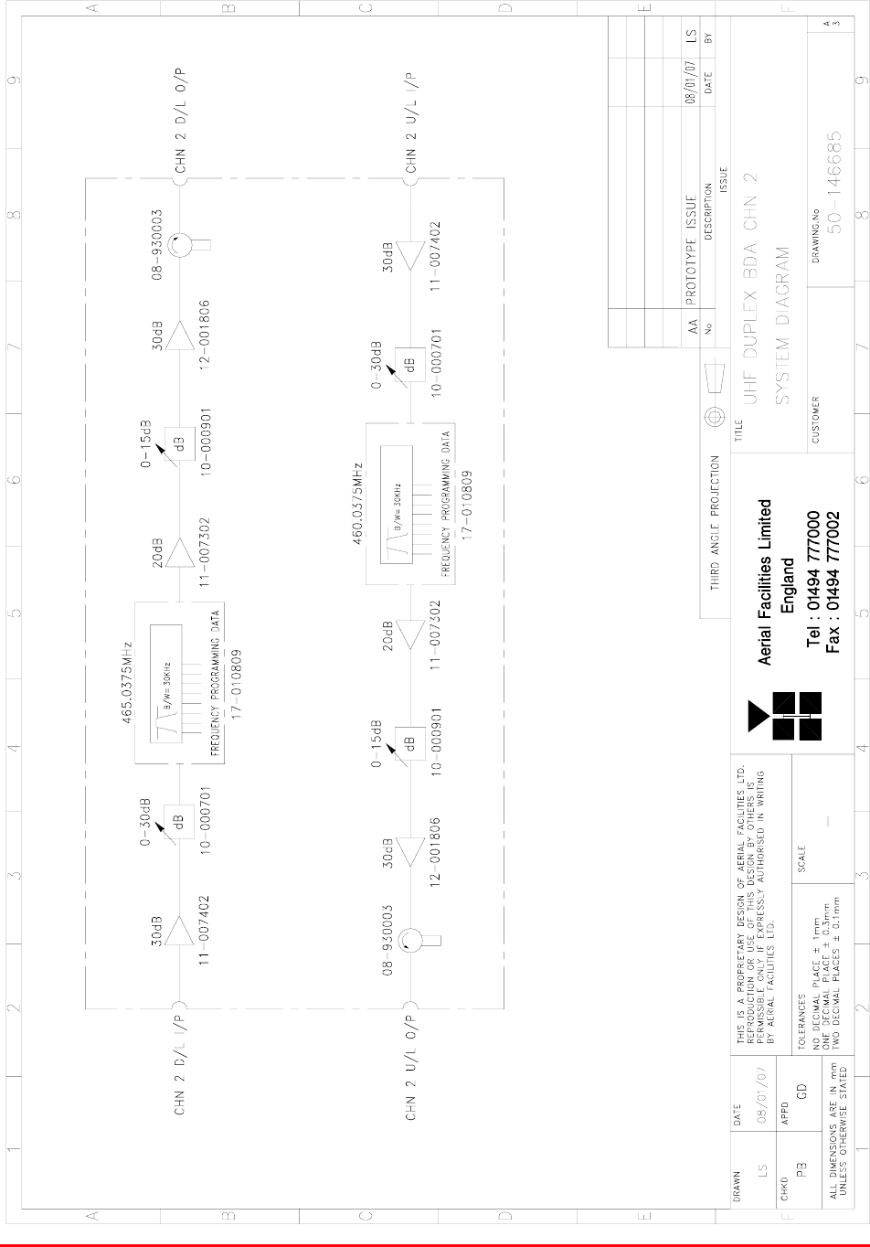
4.2.8 UHF Duplex Channel 2 BDA (50-146605)
See section 4.2.7
4.2.8.1UHF Duplex Channel 2 BDA System Diagram, Drg. # 50-146685

Bronx Justice Centre Radio Repeaters
Handbook Number: 80-283501HBKM Page: 57 of 86
4.2.9 UHF Duplex Channel 3 BDA (50-146606)
See section 4.2.7
4.2.9.1UHF Duplex Channel 3 BDA System Diagram, Drg. # 50-146686
Bronx Justice Centre Radio Repeaters
Handbook Number: 80-283501HBKM Page: 58 of 86
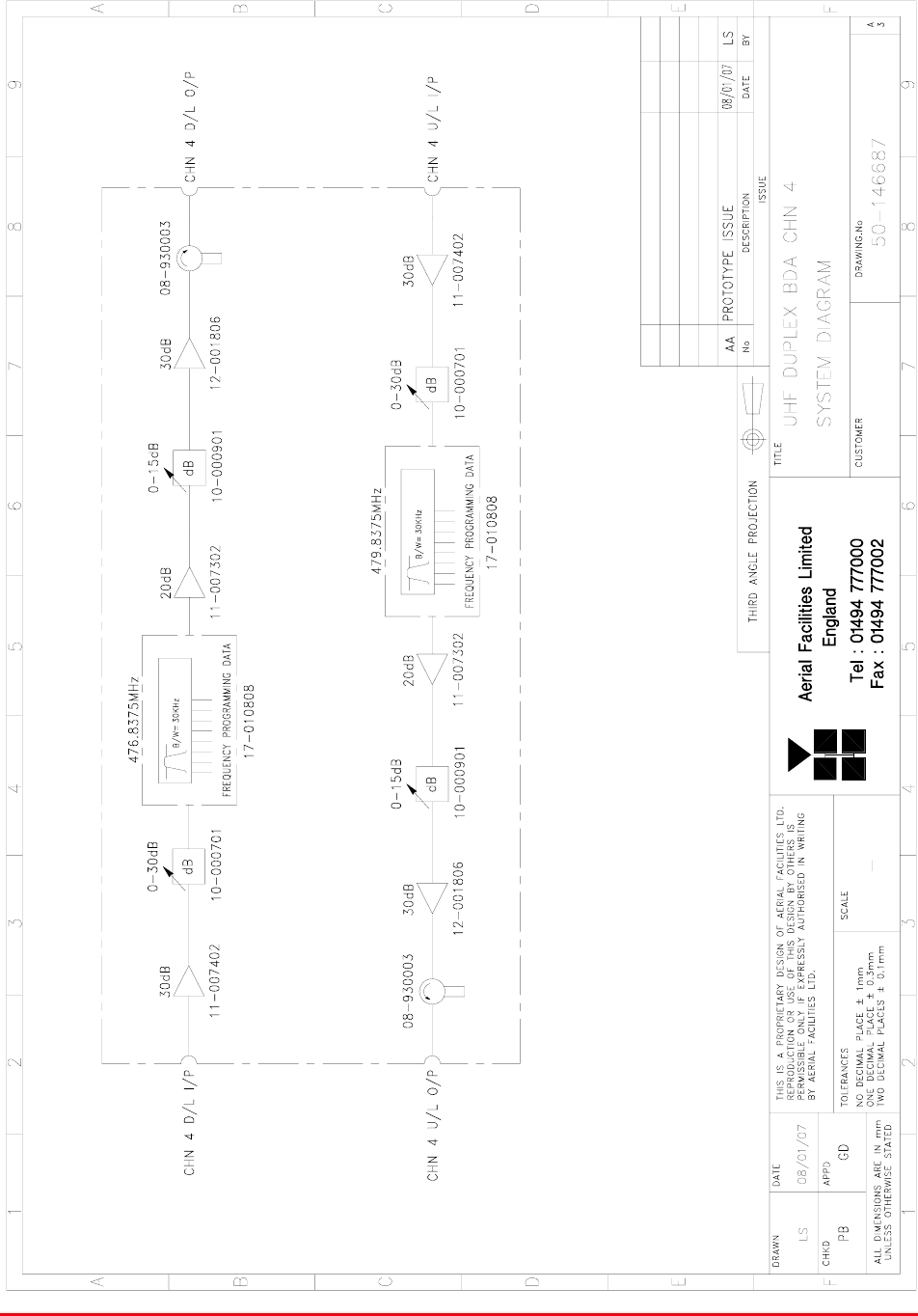
4.2.10 UHF Duplex Channel 4 BDA (50-146607)
See section 4.2.7
4.2.10.1 UHF Duplex BDA Channel 4 System Diagram, Drg. # 50-146687
Bronx Justice Centre Radio Repeaters
Handbook Number: 80-283501HBKM Page: 59 of 86
4.2.11 UHF Duplex Channel 5 BDA (50-146608)
See section 4.2.7
4.2.11.1 UHF Duplex Channel 5 System Diagram, Drg. # 50-146688
Bronx Justice Centre Radio Repeaters
Handbook Number: 80-283501HBKM Page: 60 of 86
4.2.12 UHF Duplex Channel 6 BDA (50-146612)
See section 4.2.7
4.2.12.1 UHF Duplex Channel 6 BDA System Diagram, Drg. # 50-146692
Bronx Justice Centre Radio Repeaters
Handbook Number: 80-283501HBKM Page: 61 of 86
4.2.13 UHF Uplink Combiner Shelf (50-146609)
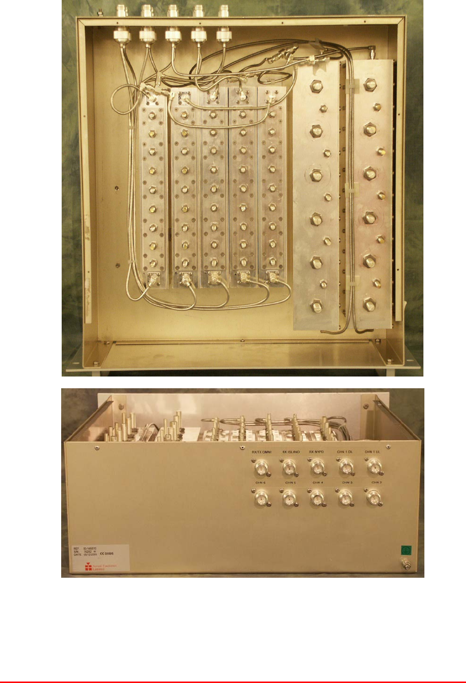
4.2.13.P UHF Uplink Combiner Shelf Photographs
Bronx Justice Centre Radio Repeaters
Handbook Number: 80-283501HBKM Page: 62 of 86
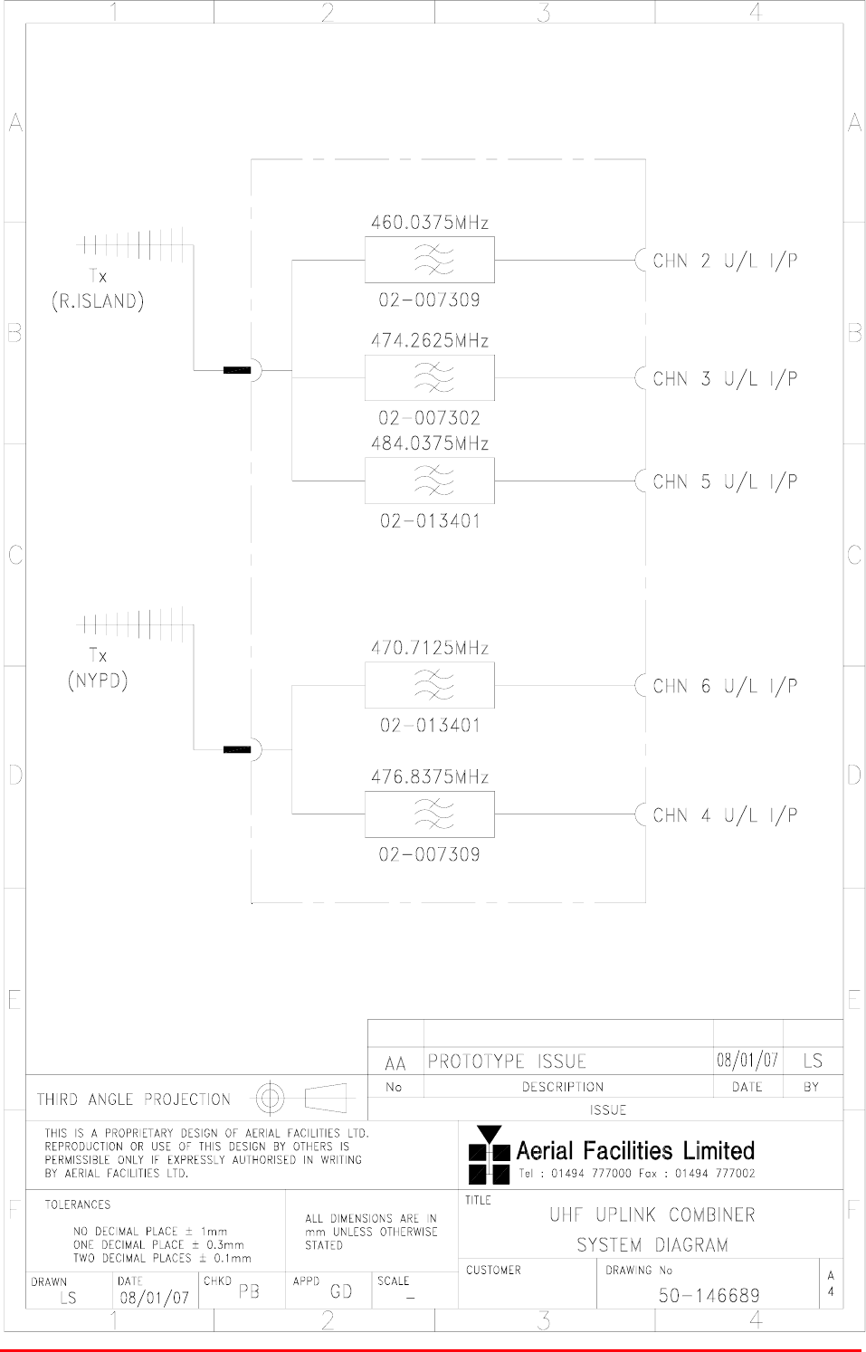
4.2.13.1 Description
This uplink combiner receives all the UHF signals from the different duplex cell enhancer shelves and
couples them together using a combination of bandpass filters and hybrids to the single Tx antenna.
This is a passive only shelf and has no need of a power supply or alarms.
4.2.13.2 Technical Specification
PARAMETER SPECIFICATION
Height: 4U
Width: 19" (482.6mm)
Shelf
dimensions: Depth: <450mm (excluding connectors & handles)
operational: -20°C to +60°C Temperature
range: storage: -40°C to +70°C
Weight: <10kg
Impedance: 50ȍ
Humidity: 5 – 95% non-condensing
RF Connectors: N type female
Environmental protection: IP44
Case: Iridite NCP coating
Heatsinks: None
Handles: Silver anodised aluminium alloy
Finish:
Fascia Painted to RAL7035
4.2.13.3 Parts List
AFL Part Nǀ.Part Description Qty.
02-007302 SDF C/L5P VAR.BW TOP SMA 40 mm POST 1
02-007309 SDF C/L5P VAR.BW TOP SMA 50mm POST 1
02-013401 6P CL FLTR(0.5 min BW) LARGE SMA ASSY 2
02-020001 UHF 2 LN NOTCH FILTER SMA 1
05-000104 TRANS.HYBRD.COUPL.3 PORT 50W INT.L 2
19-001022K 4U CHASSIS KIT (450mm deep) 1
91-030002 N ADAPTOR PANEL FEMALE:FEMALE 7
91-130001 SMA ADAPT 'T' ALL FEMALE 3 GHz 3
Bronx Justice Centre Radio Repeaters
Handbook Number: 80-283501HBKM Page: 63 of 86
4.2.13.4 UHF Uplink Combiner Shelf System Diagram, Drg. # 50-146689
Bronx Justice Centre Radio Repeaters
Handbook Number: 80-283501HBKM Page: 64 of 86
4.2.14 UHF Downlink Splitter Shelf (50-146610)
4.2.14.P UHF Downlink Splitter Shelf Photographs
Bronx Justice Centre Radio Repeaters
Handbook Number: 80-283501HBKM Page: 65 of 86
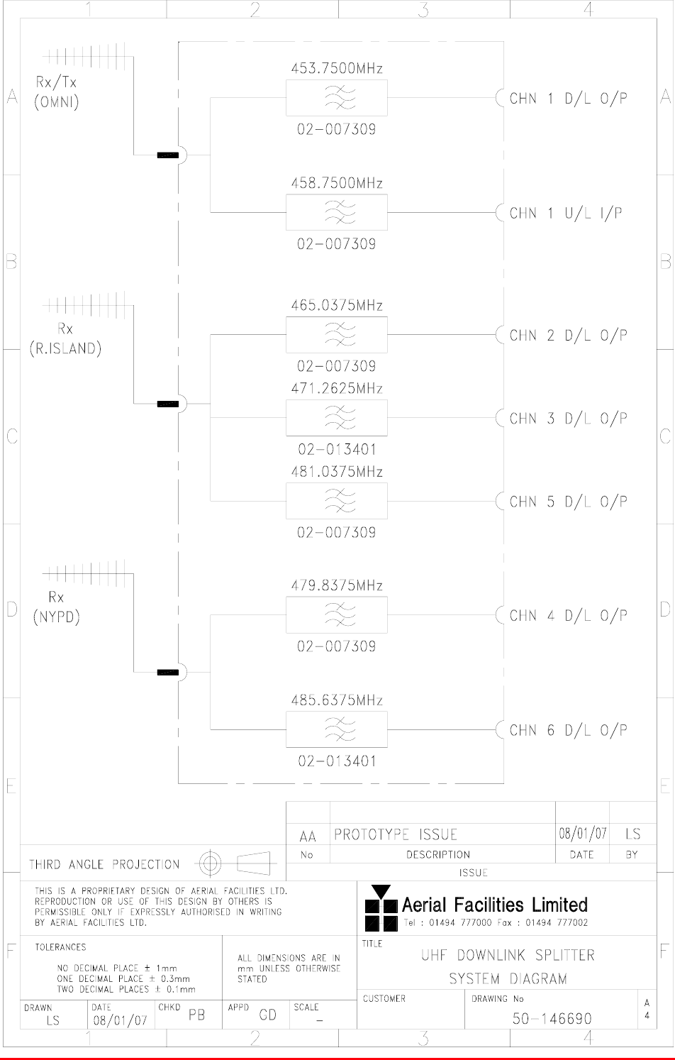
4.2.14.1 Description
This UHF downlink splitter shelf couples the received UHF signals to the cell enhancers via bandpass
filters and hybrids. This passive shelf has no connection to any power supply and no alarms.
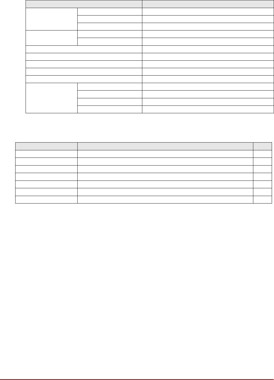
4.2.14.2 Technical Specification
PARAMETER SPECIFICATION
Height: 4U
Width: 19" (482.6mm)
Shelf
dimensions: Depth: <450mm (excluding connectors & handles)
operational: -20°C to +60°C Temperature
range: storage: -40°C to +70°C
Weight: <10kg
Impedance: 50ȍ
Humidity: 5 – 95% non-condensing
RF Connectors: N type female
Environmental protection: IP44
Case: Alocrom 1200/Iridite NCP coating
Heatsinks: None
Handles: Anodised aluminium alloy
Finish:
Fascia Painted to RAL7035
4.2.14.3 Parts List
AFL Part Nǀ.Part Description Qty.
02-007309 SDF C/L5P VAR.BW TOP SMA 50mm POST 3
02-013401 6P CL FLTR (0.5 min BW)LARGE SMA ASSY 2
02-020001 UHF 2 LN NOTCH FILTER SMA 2
05-002603 UHF 3dB SPLITTER SMA 1
19-001022K 4U CHASSIS KIT (450mm deep) 1
91-030002 N ADAPTOR PANEL FEMALE:FEMALE 7
91-130001 SMA ADAPT 'T' ALL FEMALE 3 GHz 4
Bronx Justice Centre Radio Repeaters
Handbook Number: 80-283501HBKM Page: 66 of 86
4.2.14.4 UHF Downlink Splitter Shelf System Diagram, Drg. # 50-146690
Bronx Justice Centre Radio Repeaters
Handbook Number: 80-283501HBKM Page: 67 of 86
4.3 800MHz Channel Selective Cell Enhancer Rack (50-146701)
4.3.1 Description
The 800MHz cell enhancer consists of four dedicated shelves and features two, separate, IF
channels tuned by independent channel selective modules (one 5.0MHz B/W, one 3.0MHz). The
power supply shelf provides all the DC needed by the whole 800MHz system, driven from the local
mains supplies. Alarms are provided from each active device and all are ‘looped’ to form a normally
closed fail-safe alarm (locally for each shelf and globally for the whole enhancer/rack). This loop
alarm is easily configured to join any other similarly wired system. Operators should be aware that the
8U BDA shelf and the 100W amplifier shelf are at the weight limit for a one-person lift. If in doubt do
not attempt to lift these shelves alone!
No battery backup is provided for this system, should the mains supply fail, the 800MHz system will
not function.
4.3.2 Technical Specification
PARAMETER SPECIFICATION
Height: 43U Standard Eldon Vented Rack
Width: 19" (482.6mm)
Rack
Depth: 600mm
Height: See parts lists
Width: 19" (482.6mm)
Shelves:
Depth: <450mm (excluding heatsinks, connectors,
handles and feet)
operational: -20°C to +60°C Temperature
range: storage: -40°C to +70°C
Weight: >100kg
Humidity: 5 – 95% non-condensing
RF Connectors: N type female
Environmental protection: IP44
Supply cable: All shelves supplied from dedicated PSU shelf
* Note: Individual shelf weights not specified.
4.3.3 Parts List
AFL Part Nǀ.Part Description Qty.
50-146702 800MHz CHN SELECT UL AND DL TRAY 1
50-146703 800MHz CHN SELECT POWER AMPLIFIER 1
50-146704 800MHz CHANNEL SELECTIVE PSU 1
80-054020 600mm DEEP SUPPORT BRACKET 8
80-063654 1U BLANKING PANEL (BS) RAL 7035 1
80-063655 2U BLANKING PANEL (BS) RAL 7035 3
90-100011 IEC MAINS LEAD '6 AMP' for USA 1
91-000002 N PLUG RG223:U 14
91-030002 N ADAPTOR PANEL FEMALE:FEMALE 7
97-500175 ELDON 43U 600 x 600 RACK (VENTED LID) 1
99-000082 PALLET 900 x 900 x 7ply FOR RACKS 1
Bronx Justice Centre Radio Repeaters
Handbook Number: 80-283501HBKM Page: 68 of 86
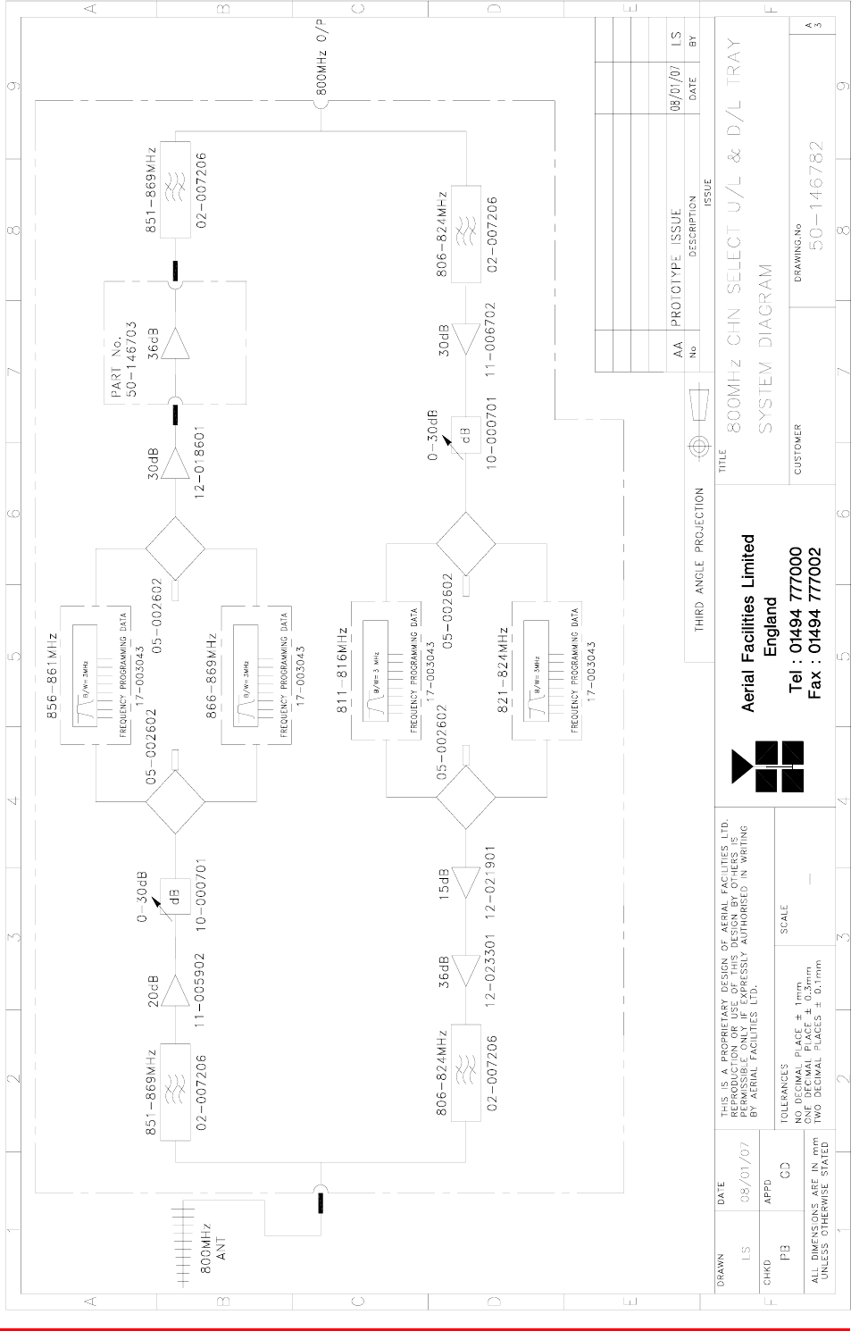
4.3.4 800MHz Channel Selective C.E. System Diagram, Drg. # 50-146782
Bronx Justice Centre Radio Repeaters
Handbook Number: 80-283501HBKM Page: 69 of 86
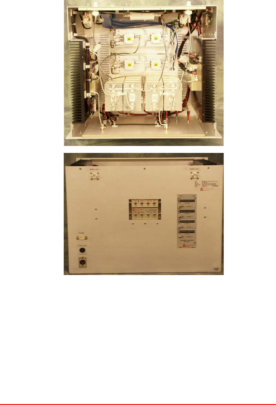
4.4 Channel Selective Uplink & Downlink Shelf (50-146702)
4.4.P Uplink & Downlink Shelf Photographs
Bronx Justice Centre Radio Repeaters
Handbook Number: 80-283501HBKM Page: 70 of 86
4.4.1 Uplink & Downlink Shelf Description
This 8U shelf holds all the electronics modules for the 800MHz BDA except for the downlink power
amplifier shelf and the PSU shelf. The alarms are a volt-free, relay contact pair, ‘D’ connector pins 1 &
2.
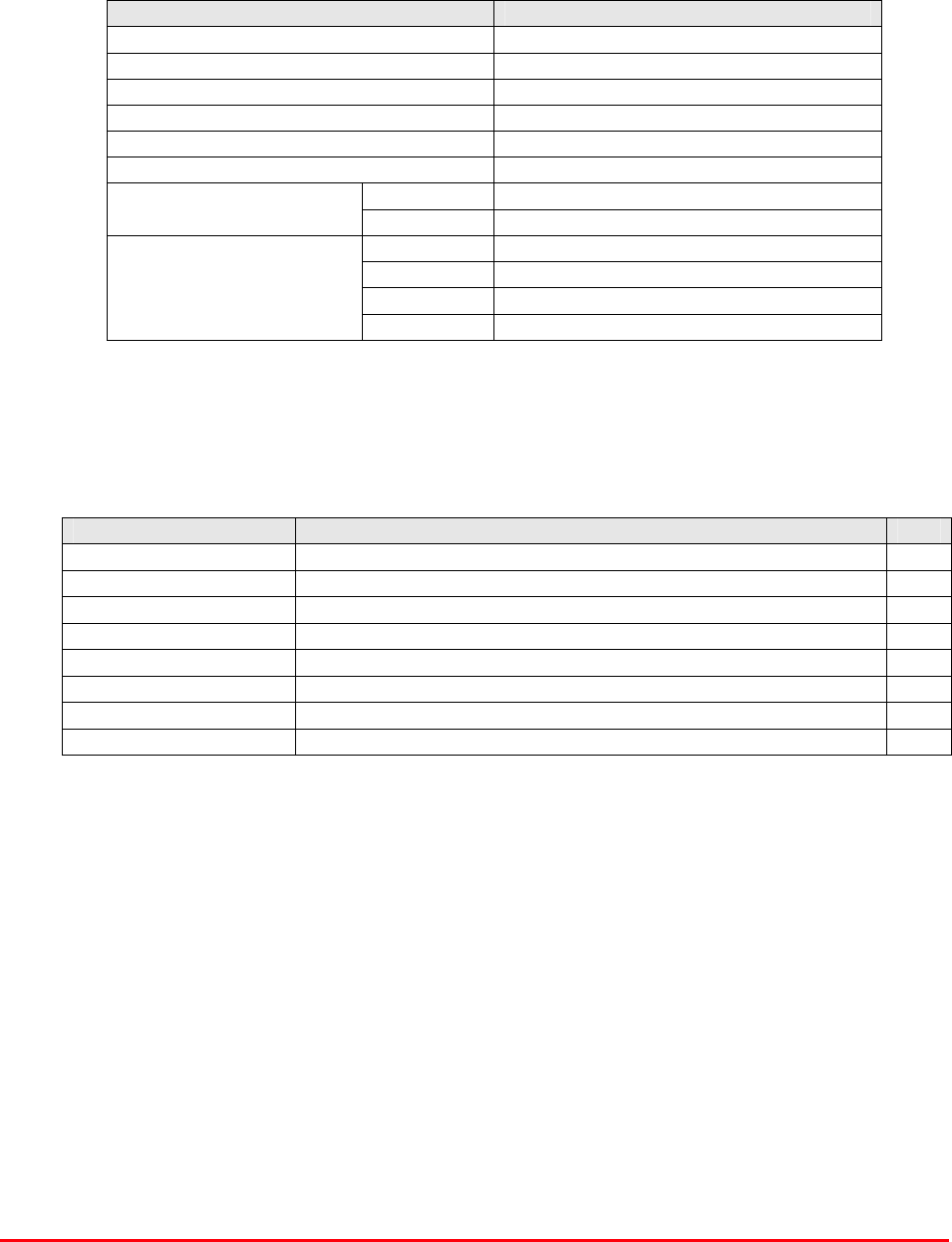
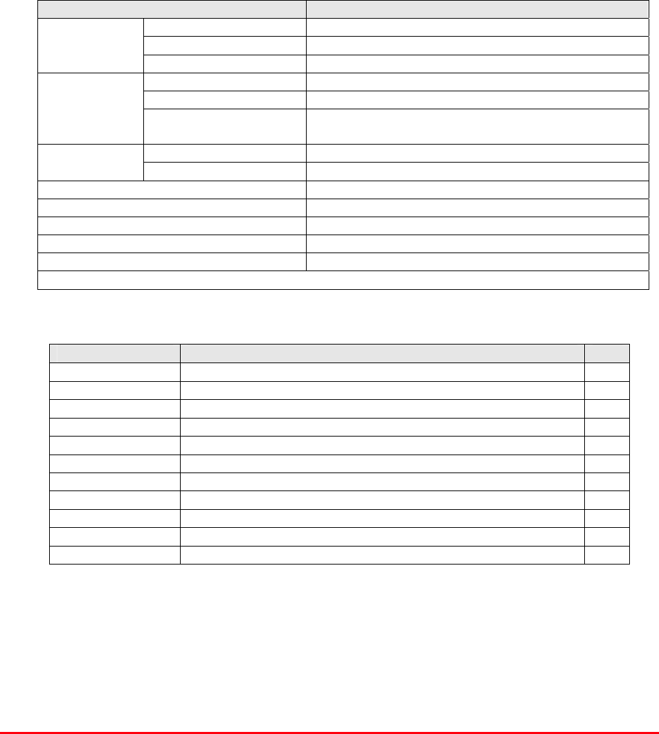
4.4.2 Uplink & Downlink Shelf Electrical Specifications
PARAMETER SPECIFICATION
851-869 MHz (downlink)
800MHz tuned frequency ranges: 806-824 MHz (uplink)
856-861MHz
IF Band select downlink channels: 866-869MHz
811-816MHz
IF Band select uplink channels: 821-824MHz
IF Bandwidths: 3MHz or 5MHz
Gain Adjustment: 0 - 30dB (in 2dB steps)
Uplink Power: >10Watts
Downlink Power: >80-100Watts
AGC: Fitted in all channel selective modules
Noise Figure: <6dB (@ maximum gain)
VSWR: better than 1.5:1
Impedance: 50ȍ
RF Connectors: N type, female
Alarms Fitted:
(‘D’ connector, pins 1 & 2) 1 Amplifiers
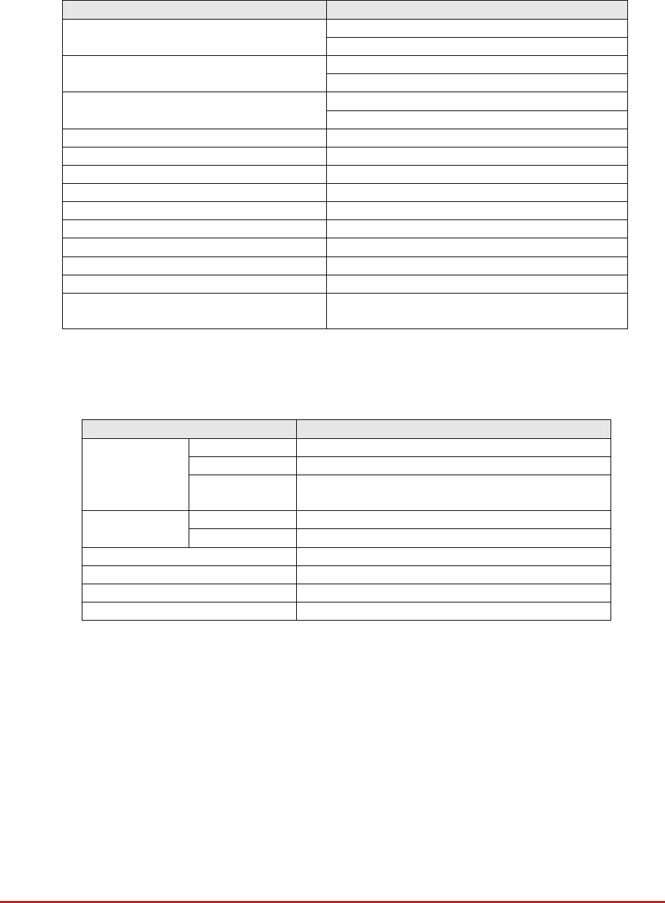
4.4.3 Uplink & Downlink Shelf Mechanical Specifications
PARAMETER SPECIFICATION
Height: 8U
Width: 19" (482.6mm)
Shelf:
Depth: <450mm(excluding heatsinks, connectors,
handles and feet)
operational: -20°C to +60°C Temperature
range: storage: -40°C to +70°C
Weight: <20kg
Humidity: 5 – 95% non-condensing
RF Connectors: N type female
Environmental protection: IP44
4.4.4 Uplink & Downlink Shelf System Diagram See section 4.3.4

Bronx Justice Centre Radio Repeaters
Handbook Number: 80-283501HBKM Page: 71 of 86
4.4.5 Uplink & Downlink Shelf Parts List
AFL Part Nǀ.Part Description Qty.
02-007206 900MHz 8POLE 15-25MHz B/W "SMA" 4
05-002603 UHF 3dB SPLITTER SMA 4
10-000701 1/4W0-30dB SWITCHED ATTENUATOR 2
11-005902 900MHz LOW NOISE AMP WITH RELAY ASS 1
11-006702 GA 800-1000MHz LNA 29dB (WITH RELAY) 1
12-018601 POWER AMPLIFIER 900MHz 5W 1
12-021901 POWER AMPLIFIER 900MHz 1W +12V 1
12-023301 PA 851-866MHz 20W LINEARIZED +24V 1
13-003011 DC/DC CONVERTER 24-12V 8A PCB SUB-ASS 1
14-000225 CASE RAIL LONG R.S.A./R.F.A. 2
17-002101 CHANNEL CONTROL MODULE 1
17-002103 26WAY RIBBON CABLE LEAD 4
17-003043 CHAN MOD 820-870MHz 3.0MHz B/W 4
17-004730 ATTENUATOR MOUNTING 2
17-004733 SIMP.C.E ATTENUATOR COVER(RAL7032) 2
50-012820 CCE RACK MOUNTED 8U CHASSIS 1
50-012822 CCE RACK MOUNTED LID 1
50-012825 CCE RACK MOUNTED HEATSINK BRACKET 4
50-027720 RACK MTD CHAN C.E. MODIFIED HEATSIN 2
80-008901 12V RELAY PCB ASSEMBLY **NO LED** 1
80-090822 C/E 8U FRONT PANEL, AFL (RAL7035) 1
91-030002 N ADAPTOR PANEL FEMALE:FEMALE 2
91-130001 SMA ADAPT 'T' ALL FEMALE 3 GHz 2
91-130005 SMA BULKHEAD ADAPTOR F/F 2
91-500001 POWER PLG 3 PIN PNL.MOUNT NC-X 1
91-510002 3 PIN STRAIGHT FREE SOC.NC-X. 1
91-510032 20A SOCKET CONTACT PIN 2
91-600005 'D' 9 WAY SOCKET S/B TERM 2
91-600014 'D' 9 WAY SOCKET S/B (NON FILTERED) 6
91-600015 'D' 9 WAY PLUG S/B (NON FILTERED) 3
91-660001 2W5 MIXED D TYPE SOCKET (7 WAY) 1
91-700017 ICD 15 WAY 0.1' CONNECTOR 1
96-600003 INSULATING BOOT D.C. 1
96-700034 LED RED 5mm IP67 INTEGRAL RES. 24V 1
96-700035 LED GREEN 5mm IP67 INTEGRAL RES 24V 1
97-400005 HANDLE TYPE H6802 3U [ALLOY] 2
Bronx Justice Centre Radio Repeaters
Handbook Number: 80-283501HBKM Page: 72 of 86
4.5 800MHz Downlink Power Amplifier Shelf (50-146703)
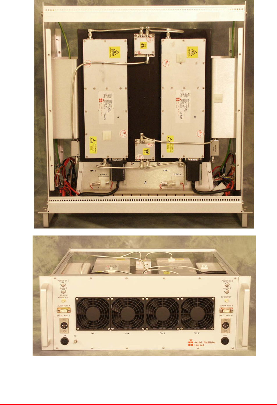
4.5.P Downlink Power Amplifier Shelf Photographs
Bronx Justice Centre Radio Repeaters
Handbook Number: 80-283501HBKM Page: 73 of 86
4.5.1 Downlink Power Amplifier Shelf Description
The 100W amplifier shelf is a linearised Class A amplifier where 4 linearised power amplifiers are
combined together in a series/parallel configuration which yields approximately double the output
power per path. Its housing is a 4U 19” Rack with SMA connectors for the RF input/output, 2 D-
Type connectors for the alarm function and 2 DC connectors with fuse for the 24 DC supply. Its
cooling is realized by fans mounted on the front panel.
It has a built in Current Fault Alarm Function with the four amplifiers in two summary alarm paths.
The summary alarm on D connector ‘A’ will show an alarm for the two amplifiers mounted on the
top of the shelf. The summary alarm on D connector ‘B’ will show an alarm for the two amplifiers
mounted at the bottom of the shelf.
4.5.2 Downlink Power Amplifier Shelf Electrical Specifications
PARAMETER SPECIFICATION
Frequency range: 851-866MHz
Bandwidth: <30MHz
Gain: 36dB (typical)
Gain Flatness: <0.5dB
1dB Compression Point: +43.5dBm (typical)
3rd order intercept: +61.5dBm (typical)
Input/Output return loss: >15dB
Connectors: SMA female
Supply: 24V DC @ 16-18Amps
Alarms: ‘D’ conn. Pins 1 & 2 (x2)
4.5.3 Downlink Power Amplifier Shelf Mechanical Specification
PARAMETER SPECIFICATION
Height: 4U
Width: 19" (482.6mm)
Shelf:
Depth: <450mm(excluding heatsinks,
connectors, handles and feet)
operational: -20°C to +60°C Temperature
range: storage: -40°C to +70°C
Weight: <25kg
Humidity: 5 – 95% non-condensing
RF Connectors: N type female
Environmental protection: IP44
4.5.4 Downlink Power Amplifier Shelf System Diagram
See section 4.3.4

Bronx Justice Centre Radio Repeaters
Handbook Number: 80-283501HBKM Page: 74 of 86
4.5.5 Downlink Power Amplifier Shelf Parts List
AFL Part Nǀ.Part Description Qty.
05-002602 900MHz SPLITTER/COMBINER, 20W 6
05-002622 SPLITTER/COMBINER AUX. MTG PLATE 6
12-023301 PA 851-866MHz 20W LINEARIZED +24V 4
80-008902 24V RELAY PCB ASSEMBLY **NO LED** 2
80-245121 CLASS A LINEARIZED HEATSINK 2
80-245122 100WTETRA LINEARIZED H'SINK MTG BKT 2
80-245123 100WTETRA LINEARIZED SIDE PANEL 2
80-245124 100WTETRA LINEARIZED RACK LID 2
80-245125 100WTETRA LINEARIZED FRONT PANEL 1
80-245126 100WTETRA LINEARIZED DUCT END PLATE 2
80-245128 100WTETRA LINEARIZED DUCT MTG BLOCK 4
80-245129 100WTETRA LINEARIZED LID MTG BKT 4
80-245130 100WTETRA LINEARIZED DUCT TOP COVER 1
80-245131 100WTETRA LINEARIZED DUCT BOT COVER 1
80-245132 CLASS A LINEARIZED AMP CABLE TIDY 2
90-010021 RF CABLE SUPFLEX SMA R/A MALE 100mm 4
90-010024 RF CABLE SUPFLEX SMA R/A MALE 400mm 2
90-010026 RF CABLE SUPFLEX SMA R/A MALE 150mm 6
90-010027 RF CABLE SUPFLEX SMA R/A MALE 250mm 2
91-130005 SMA BULKHEAD ADAPTOR F/F 2
91-500001 POWER PLG 3 PIN PNL.MOUNT NC-X 2
91-600015 'D' 9 WAY PLUG S/B (NON FILTERED) 2
91-600019 'D'15 WAY SHELL (2W7) 4
91-640004 LARGE PIN FOR 91-660001 D SOCKET 8
91-660001 2W5 MIXED D TYPE SOCKET (7 WAY) 4
91-700017 ICD 15 WAY 0.1' CONNECTOR 2
91-700036 MISC 3 WAY PLUG HOUSING 4
91-700037 MISC 4 WAY PLUG HOUSING 2
91-700038 MISC PLG PIN FOR 3WAY HOUSING 14AWG 32
91-700039 MISC 3 WAY SOCKET HOUSING 6
91-700040 MISC 4 WAY SOCKET HOUSING 2
91-700042 MISC SOC.PIN FOR 3WAY HOUSING 14AWG 12
92-110003 CABLE CLIPS LARGE 13mm (WHITE) 0
92-300010 M3 x 12 HEX SPACER BRASS N:P 4
92-340001 M3 x 8mm 'D'CONNECTOR SCREW LOCK 12
92-700008 M3 BLUE RING TERMINAL % 4
92-700010 M5 BLUE RING TERMINAL 2
92-700057 FEM 2.8 x 0.8 PUSH ON BARE TERM RED 8
96-100004 32mm 20A (16A max load) FUSE HOLDER 2
96-110005 315mA FUSE GLASS A/SURGE 20 x 5mm 4
96-110015 T 15A A/SURGE FUSE 1.25' 2
96-110040 BULGIN IN-LINE FUSEHOLDER 20mm 4
96-400002 80 x 80mm 24V DC FAN SUNON 4
96-400003 PLASTIC FINGER GUARD 80 x 80mm 4
96-600003 INSULATING BOOT D.C. 2
96-700034 LED RED 5mm IP67 INTEGRAL RES. 24V 2
96-700035 LED GREEN 5mm IP67 INTEGRAL RES 24V 2
97-400002 HANDLE TYPE H6803 4U.[ALLOY] 2
97-600004 19" SUBRACK REAR RAIL 2
97-600005 19" SUBRACK FRONT RAIL 2
97-600008 19" SUBRACK TAPPED STRIP 2
97-600016 19" 4U SUBRACK MOUNTING FLANGE 2
Bronx Justice Centre Radio Repeaters
Handbook Number: 80-283501HBKM Page: 75 of 86
4.6 Multiband Combiner Shelf (50-146705)
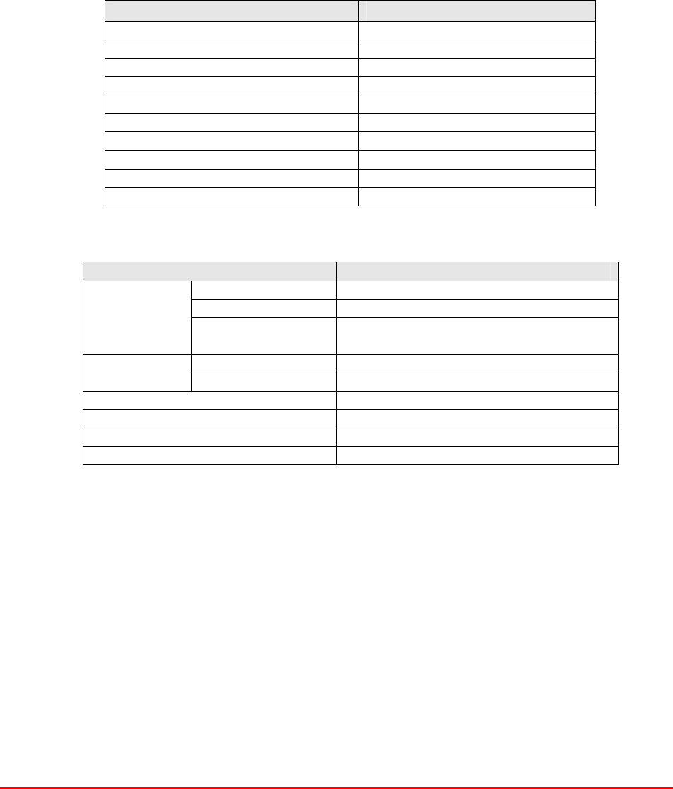
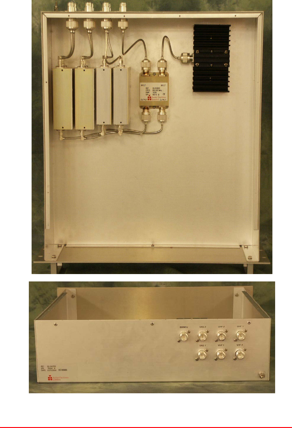
4.6.P Multiband Combiner Shelf Photographs
Bronx Justice Centre Radio Repeaters
Handbook Number: 80-283501HBKM Page: 76 of 86
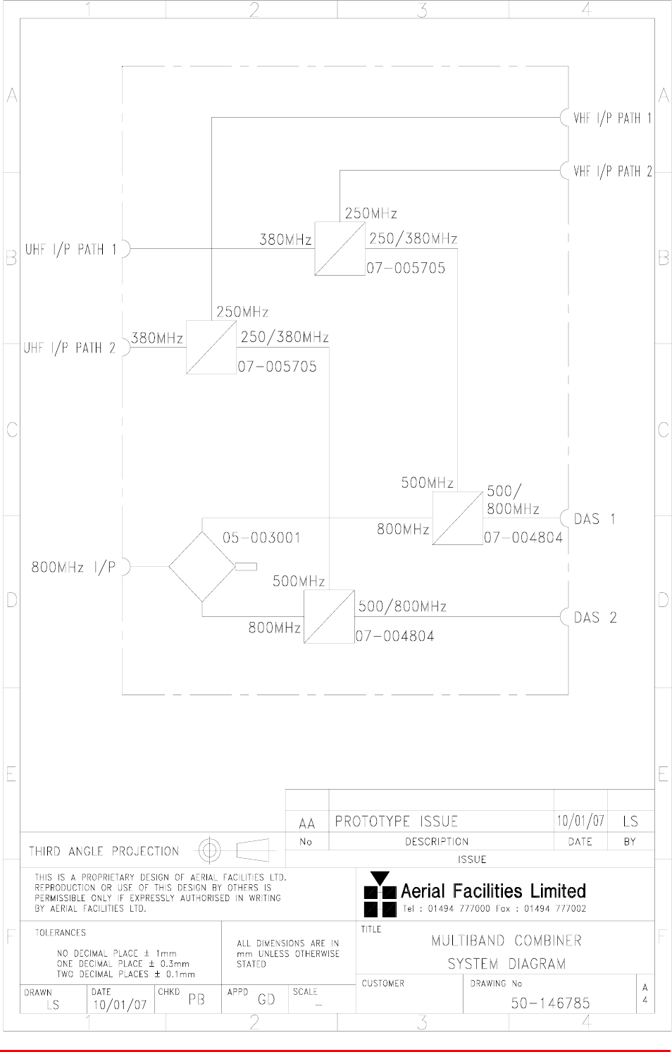
4.6.1 Multiband Combiner Shelf Description
The multiband combiner performs the task of receiving all three frequency bands (VHF, UHF &
800MHz), passing them through a series of crossband couplers and a hybrid combiner to the two exit
ports, DAS1 & DAS2. This is an entirely passive unit using no active devices, no power supply and
therefore no alarm interface.
4.6.2 Multiband Combiner Shelf Technical Specification
PARAMETER SPECIFICATION
153.965MHz* (Ch 1)
154.755MHz
154.785MHz
154.980MHz
158.925MHz* (Ch 2)
VHF downlink
151.355MHz* (Ch 1)
154.6575MHz* (Ch 2)
154.755MHz
154.785MHz
VHF Frequencies:
154.980MHz
VHF uplink
453.7500MHz
465.0375 MHz
471.2625 MHz
479.8375 MHz
481.0375 MHz
485.6375 MHz
UHF downlink
458.7500 MHz
460.0375 MHz
470.7125 MHz
474.2625 MHz
476.8375 MHz
UHF Frequencies:
484.0375 MHz
UHF uplink
851-869 MHz (downlink)
800MHz tuned frequency ranges: 806-824 MHz (uplink)
VSWR: better than 1.5:1
Impedance: 50ȍ
RF Connectors: N type, female
Alarms Fitted: None
Environmental protection: IP44
Weight: <10kg
Height: 3U
Width: 19" (482.6mm)
Shelf:
Depth: <450mm(excluding heatsinks, connectors,
handles and feet)
operational: -20°C to +60°C Temperature
range: storage: -40°C to +70°C
* = Duplex channel
4.6.3 Multiband Combiner Shelf Parts List
AFL Part Nǀ.Part Description Qty.
05-003001 COUPLER 900MHz 4 PORT(THC-900) 1
07-004804 500/800MHz CROSS BAND COUPLER SMA 2
07-005705 CROSSBAND CPLR XC 250/380 SMA 2
09-002101 50W DUMMY LOAD DC-2.5GHz N FEMALE 1
19-000922K 3U CHASSIS KIT (450mm deep) 1
91-030002 N ADAPTOR PANEL FEMALE:FEMALE 7
Bronx Justice Centre Radio Repeaters
Handbook Number: 80-283501HBKM Page: 77 of 86
4.6.4 Multiband Combiner Shelf System Diagram, Drg. # 50-146785

Bronx Justice Centre Radio Repeaters
Handbook Number: 80-283501HBKM Page: 78 of 86
5. INSTALLATION
5.1 Initial Installation Record
When this equipment is initially commissioned, please use the equipment set-up record sheet in
Appendix B. This will help both the installation personnel and AFL should these figures be needed for
future reference or diagnosis.
6. FAULT FINDING & MAINTENANCE
6.1 General Fault Finding Procedures
In the event that the performance of the system is suspect, a methodical and logical approach to the
problem will reveal the cause of the difficulty.
Transmissions from the main base stations are passed though the system to the mobile radio
equipment; this could be a handheld radio or a transceiver in a vehicle. This path is referred to as the
downlink. The return signal path from the mobile radio equipment to the base station is referred to as
the uplink.
The first operation is to check the alarms of each of the active units and determine that the power
supplies to the equipment are connected and active.
This can be achieved remotely (via CEMS, the RS232 Coverage Enhancement Management System,
if fitted), or locally with the front panel LEDs. The green LED on the front panel should be illuminated,
while the red alarm indicator should be off.
If an alarm is on, then that individual shelf/module must be isolated and individually tested against the
original test specification.
The individual amplifier units have a green LED showing through a hole in their case, which is
illuminated if the unit is working correctly.
If an amplifier is suspect, check the DC power supply to the unit. If no other fault is apparent use a
spectrum analyser to measure the incoming signal level at the input and then after reconnecting the
amplifier input, measure the output level. Consult with the system diagram to determine the expected
gain and compare result.
In the event that there are no alarms on and all units appear to be functioning it will be necessary to
test the system in a systematic manner to confirm correct operation.

Bronx Justice Centre Radio Repeaters
Handbook Number: 80-283501HBKM Page: 79 of 86
5.2 Downlink
Confirm that there is a signal at the expected frequency and strength from the base station. If this is
not present then the fault may lay outside the system. To confirm this, inject a downlink frequency
signal from a known source at the master site BTS input and check for output at the remote site
feeder output.
If a signal is not received at the output it will be necessary to follow the downlink path through the
system to find a point at which the signal is lost. The expected downlink output for the given input can
be found in the end-to-end test specification.
5.3 Uplink
Testing the uplink involves a similar procedure to the downlink except that the frequencies used are
those transmitted by the mobile equipment.
5.4 Fault repair
Once a faulty component has been identified, a decision must be made on the appropriate course to
carry out a repair. A competent engineer can quickly remedy typical faults such as faulty connections
or cables. The exceptions to this are cable assemblies connecting bandpass filter assemblies that are
manufactured to critical lengths to maintain a 50-ohm system. Care should be taken when replacing
cables or connectors to ensure that items are of the correct specification. The repair of component
modules such as amplifiers and bandpass filters will not usually be possible in the field, as they
frequently require specialist knowledge and test equipment to ensure correct operation. It is
recommended that items of this type are replaced with a spare unit and the faulty unit returned to AFL
for repair.
5.5 Checking service
Following the repair of any part of the system it is recommended that a full end-to-end test is carried
out in accordance with the test specification and that the coverage is checked by survey.
It is important to bear in mind that the system includes a radiating cable network and base stations
that may be faulty or may have been damaged.
5.6 Service Support
Advice and assistance with maintaining and servicing this system are available by contacting Aerial
Facilities Ltd.
5.7 Tools & Test Equipment
The minimum tools and test equipment needed to successfully service this AFL product are as
follows:-
Spectrum analyser: 100kHz to 2GHz (Dynamic range = 90dB).
Signal Generator: 30MHz to 2GHz (-120dBm to 0dBm o/p level).
Attenuator: 20dB, 10W, DC-2GHz, (N male – N female).
Test Antenna: Yagi or dipole for operating frequency.
Digital multi-meter: Universal Volt-Ohm-Amp meter.
Test cable x 2: N male – N male, 2M long RG214.
Test cable x 2: SMA male – N male, 1m long RG223.
Hand tools: Philips #1&2 tip screwdriver.
3mm flat bladed screwdriver.
SMA spanner and torque setter.

Bronx Justice Centre Radio Repeaters
Handbook Number: 80-283501HBKM Page: 80 of 86
5.8 General Maintenance Procedures
Many of the active modules contain semiconductor devices utilising MOS technology, which can be
damaged by electrostatic discharge. Correct handling of such modules is mandatory to ensure their
long-term reliability.
To prevent damage to a module, it must be withdrawn/inserted with care. The module may have
connectors on its underside, which might not be visible to the service operative.
5.9 Module Removal (LNAs, general procedure)
The following general rules should be followed to remove a module:
1 Remove power to the unit
2 Remove all visible connectors (RF, DC & alarm)
3 Release module retaining screws.
4 Slowly but firmly, pull the module straight out of its position. Take care not to twist/turn the
module during withdrawal. (When the module is loose, care may be needed, as there may be
concealed connections underneath).
5.10 Module Replacement (general)
1 Carefully align the module into its location then slowly push the module directly straight into its
position, taking care not to twist/turn it during insertion.
2 Reconnect all connectors, RF, alarm, power etc., (concealed connectors may have to be
connected first).
3 Replace retaining screws (if any).
4 Double-check all connections before applying power.
5.11 Power Amplifiers
1) Remove power to the unit. (Switch off at the mains/battery, or remove DC in connector)
2) Remove alarm wires from alarm screw terminal block or disconnect multi-way alarm
connector.
3) Carefully disconnect the RF input and output coaxial connectors (usually SMA)
If alarm board removal is not required, go to step 5.
4) There is (usually) a plate attached to the alarm board which fixes it to the amplifier, remove its
retaining screws and the alarm board can be withdrawn from the amplifier in its entirety. On
certain types of amplifier the alarm board is not mounted on a dedicated mounting plate; in this
case it will have to firstly be removed by unscrewing it from the mounting pillars, in most
cases, the pillars will not have not have to be removed before lifting the amplifier.
5) If the amplifier to be removed has a heatsink attached, there may be several different ways it
can have been assembled. The most commonly used method, is screws through the front of
the heatsink to threaded screw holes (or nuts and bolts), into the amplifier within the main
case. If the heatsink is mounted on the rear of the main case (e.g., against a wall in the case
of wall mounted enclosures), then the fixing method for the heatsink will be from within the
case, (otherwise the enclosure would have to be removed from the wall in order to remove the
heatsink).
When the heatsink has been removed, the amplifier may be unscrewed from the main casing by its
four corner fixings and gently withdrawn.

Bronx Justice Centre Radio Repeaters
Handbook Number: 80-283501HBKM Page: 81 of 86
Fitting a new power amplifier module will be the exact reverse of the above.
Note: Do not forget to apply fresh heatsink compound to the heatsink/main case joint and also
between the amplifier and the main case.
5.12 Low Power Amplifier Replacement
Disconnect the mains power supply and disconnect the 24V dc supply connector for the LPA.
Disconnect the RF input and output cables from the LPA.
Disconnect the alarm connector.
Remove the alarm monitoring wires from (D type connector) pins 9 and 10.
Remove the LPA module by removing the four retaining screws, replace with a new LPA module and
secure it with the screws.
Connect the RF cables to the LPA input and output connectors. Reconnect the wires to the alarm
board connector pins 9 and 10.
Reconnect the DC supply connector and turn the mains switch on.
Note: Tighten SMA connectors using only a dedicated SMA torque spanner. If SMA connectors are
over-tightened, irreparable damage will occur. . Do not use adjustable pliers to loosen/tighten SMA
connectors.
Also take care not to drop or knock the module as this can damage (or misalign in the case of tuned
passive modules) sensitive internal components. Always store the modules in an environmentally
friendly location
5.13 Module Transportation
To maintain the operation, performance and reliability of any module it must be stored and
transported correctly. Any module not installed in a whole system must be kept in an anti-static bag or
container. These bags or containers are normally identified by being pink or black, and are often
marked with an ESD label. Any module sent back to AFL for investigation/repair must be so
protected. Please contact AFL’s quality department before returning a module.

Bronx Justice Centre Radio Repeaters
Handbook Number: 80-283501HBKM Page: 82 of 86
APPENDIX A
Amendment List Record Sheet
Issue No. Date Incorporated by Page Nos.
Amended Reason for new issue
A 18/10/2006 CMH 1st Draft
1 CMH 1st Issue
Document Ref.: 80-283501HBKM

Bronx Justice Centre Radio Repeaters
Handbook Number: 80-283501HBKM Page: 83 of 86
Glossary of Terms
Repeater or
Cell Enhancer
A Radio Frequency (RF) amplifier which can simultaneously
amplify and re-broadcast Mobile Station (MS) and Base
Transceiver Station (BTS) signals.
Band Selective
Repeater
A Cell Enhancer designed for operation on a range of channels
within a specified frequency band.
Channel Selective
Repeater
A Cell Enhancer, designed for operation on specified channel(s)
within a specified frequency band. Channel frequencies may be
factory set or on-site programmable.
AC Alternating Current
AGC Automatic Gain Control
BBU Battery Backup Unit
BTS Base Transceiver Station
CEMS Coverage Enhanced Management System
C/NR Carrier-to-Noise Ratio
DC Direct Current
Downlink (D/L) RF signals TX from the BTS to the Master Site
FO Fibre Optic
GND Ground
ID Identification Number
LED Light Emitting Diode
LNA Low Noise Amplifier
LPA Low Power Amplifier
MOU Master Optical Unit
M.S. Mobile Station
MTBF Mean Time Between Failures
N/A Not Applicable
N/C No Connection
OFR On Frequency Repeater
OIP3 Output Third Order Intercept Point = RFout +(C/I)/2
PA Power Amplifier
RF Radio Frequency
RSA Receiver/Splitter Amplifier
RX Receiver
S/N Serial Number
TX Transmitter
Uplink (U/L) RF signals transmitted from the MS to the BTS
VSWR Voltage Standing Wave Ratio
WDM Wave division multiplex
Bronx Justice Centre Radio Repeaters
Handbook Number: 80-283501HBKM Page: 84 of 86
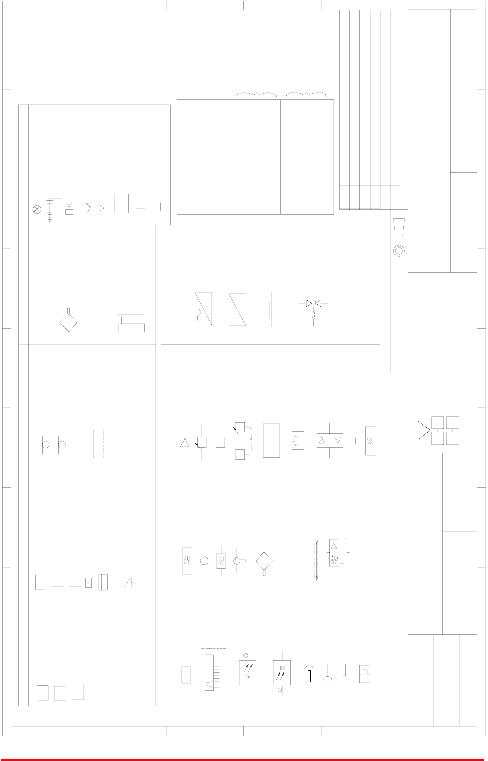
Key to AFL Drawing Symbols
AFL - STANDARD SYMBOLS
90-000001
AA
NTS
PL 10/05/00
C0-AX CABLE
C0-AX CABLE
CAT 5 CABLE
CABLES
24/FIBRE OPTIC CABLE/LINK
CABLE 1/2"
RADIATING CABLE
TAPPER/COUPLER
STATION
BASE TRANSCEIVER
MISC
HUBS
FIBRE MAIN HUB
EXPANSION HUB
BI-DIRECTIONAL AMPLIFIER
E
BTS
FMH
EH
7/8" DIA
1/2" DIA
6dB DIRECTIONAL COUPLER
10dB COUPLER
C1 0
CROSS BAND COUPLER
COUPLERS
J
JUM P E R
C6
C1 0
10dB DIRECTIONAL COUPLER
6 dB DIRECTIONAL COUPLER
DIRECTIONAL COUPLER
PANEL ANTENNA
(MOUNTED AT HIGH LEVEL)
DIRECTIONAL ANTENNA
FLAT PLATE ANTENNA
YAGI ANTENNA
ANTENNAS
REMOTE ANTENNA UNIT
OMNI ANTENNA
SP LITTERS
ANTENNA
RAU
BAND PASS FILTER
CAVITY RESONATOR
NOTCH FILTER
IS OLA TOR
HYBRID COMBINER
EARTH STUD
LEEKY FEEDER
Outputs to receivers
R.S.A
AMPLIFIER
MISC
dB
ATTENUATOR (VARIABLE)
A.G.C
AG C dB
CO NT RO L L ER
M O NITO RING
MODEM
MONITORING CONTROLLER
MODEM
(CELL ENHANCER)
FREQUENCY PROGRAMMING DATA
B / W=30 t o 200kH z
CHANNEL MODULE
FIBRE-OPTIC
MODULATOR
FIBRE-OPTIC
DEMODULATOR
LO C A L O S C I LLA TO R
(up to
16 way)
Outputs
DUMMY LOAD
LOCAL OSCILLATOR
SPLITTER
MISC
8/FIBRE OPTIC CABLE/LINK
STANDARD FOR
LEVEL (dBm)
-73 = BELOW ACCEPTABLE
SIGNAL LEVEL(dBm)
ALL AIRPORTS
BCCH (BROADCAST
IDENTITY CODE)
BSIC (BASIC SITE
LEVEL (dBm)
-83 = BELOW ACCEPTABLE
SIGNAL LEVEL(dBm)
-82 = ACCEPTABLE SIGNAL
-72 = ACCEPTABLE SIGNAL
CONTROL CHANNEL)
= READING POSITION
22 =
602 =
SIGNAL KEY
STANDARD EXCEPT
FOR AIRPORTS
(SEE BELOW)
BLADE ANTENNA
ATTE NUATOR (FIX ED)
dB
OUTIN
COUPLED
HI COM
LOW
HYBRID SPLITTER
IN
IN
OUT
OUT
IN
OUT
BYDATEDESCRIPTIONNo
ISSUE
THIRD ANGLE PROJECTION
12
3456789
A
B
C
D
E
F
123456789
A
B
C
D
E
F
Fax : 01494 777002
Tel : 01494 777000
Aerial Facilities Limited
THIS IS A PROPRIETARY DESIGN OF AERIAL FACILITIES LTD.
REPRODUCTION OR USE OF THIS DESIGN BY OTHERS IS
PERMISSIBLE ONLY IF EXPRESSLY AUTHORISED IN WRITING
BY AERIAL FACILITIES LTD.
NO DECIMAL PLACE ± 1mm
ONE DECIMAL PLACE ± 0.3mm
TWO DECIMAL PLACES ± 0.1mm
ALL DIMENSIONS ARE IN mm
UNLESS OTHERWISE STATED
CHKD
DRAWN
APPD
DATE
TOLERANCES SCALE
England
CUSTOMER DRAWING.No
TITLE
3
A
ORIGINAL ISSUE PL
23/05/00
21/06/00
PLBLADE ANTENNA ADDED1A
2A ECN3165
RF
RF
PLUG & SOCKET
FIBRE OPTIC
CONNECTOR
FC/APC
SOCKET
PLUG
MISC
DC
DC
AC TO DC PSU
DC TO DC CONVERTER
FUS E
RELAY
N.O. (CLEAR CONTACT)
N.C. (FILLED CONTACT)
COM
MB GD
26/01/04
PL
2B TEXT CORRECTION
28/07/04
PL

Bronx Justice Centre Radio Repeaters
Handbook Number: 80-283501HBKM Page: 85 of 86
EC Declaration of Conformity
In accordance with BS EN ISO/IEC 17050-1&-2:2004
Aerial Facilities Limited
Aerial House
Asheridge Road
Chesham
Buckinghamshire HP5 2QD
United Kingdom
DECLARES, UNDER OUR SOLE RESPONSIBILITY THAT THE FOLLOWING PRODUCT:
PRODUCT PART NO[S]: 50-146501, 50-146601, 50-146701
PRODUCT DESCRIPTION: Radio Repeater Equipment
IN ACCORDANCE WITH THE FOLLOWING DIRECTIVES:
1999/5/EC The Radio & Telecommunications Terminal Equipment Directive Annex V
and its amending directives
HAS BEEN DESIGNED AND MANUFACTURED TO THE FOLLOWING STANDARD[S] OR
OTHER NORMATIVE DOCUMENT[S]:
BS EN 60950 Information technology equipment.
Safety. General requirements
ETS EN 301 489-1 EMC standard for radio equipment and services.
Part 1. Common technical requirements
I hereby declare that the equipment named above has been designed to comply with the relevant
sections of the above referenced specifications. The unit complies with all essential requirements
of the Directives.
SIGNED
B S BARTON
TECHNICAL DIRECTOR DATE: 12/01/2007
Registered Office: Aerial House, Asheridge Road, Chesham, Buckinghamshire, HP5 2QD England Registered No. 4042808 (England)
www.aerialfacilities.com

Bronx Justice Centre Radio Repeaters
Handbook Number: 80-283501HBKM Page: 86 of 86
APPENDIX B
Initial Equipment Set-Up Calculations
General Information
Site Name: Client Name:
Date: AFL Equip. Model No.
Antenna Systems
Model Gain Azimuth Comments
A - Service Antenna
B – Donor Antenna
Type Loss Length Comments
C – Service Feeder
D – Donor Feeder
Initial Parameters
E – CE Output Power dBm
F – Antenna Isolation dB
G – Input signal level from donor BTS dBm
Operating Voltage V
Downlink Calculations
Parameter Comments Value
Input signal level (G) dBm
CE max. o/p power (E) dBm
Gain setting E - G dB
Isolation required (Gain + 10dB) dB
Service antenna gain (A) dB
Service antenna feeder loss (C) dB
Effective radiated power (ERP) E+A-C dBm
Attenuator setting CE gain-gain setting dB
If the input signal level in the uplink path is known and steady, use the following calculation table to
determine the gain setting. If the CE features Automatic Gain Control the attenuator should be set to
zero and if not, then the attenuation setting for both uplink and downlink should be similar.
Uplink Calculations
Parameter Comments Value
Input signal level dBm
CE max. o/p power (E) dBm
Gain setting dB
Required isolation dB
Donor antenna gain (B) dB
Donor antenna feeder loss (D) dB
Effective radiated power (ERP) E+B-D dBm
Attenuator setting (CE gain-gain setting) dB