PBE Europe as Axell Wireless 50-1465SERIES 50-146501 VHF Channelised Air Interface User Manual 50 146501 50 146601 50 146701HBKM
Axell Wireless 50-146501 VHF Channelised Air Interface 50 146501 50 146601 50 146701HBKM
Contents
- 1. User Manual 1 of 2
- 2. User Manual 2 of 2
User Manual 2 of 2


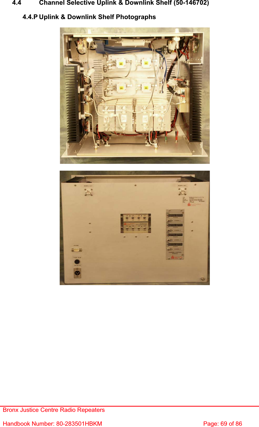
![Bronx Justice Centre Radio Repeaters Handbook Number: 80-283501HBKM Page: 71 of 86 4.4.5 Uplink & Downlink Shelf Parts List AFL Part Nǀ.Part Description Qty.02-007206 900MHz 8POLE 15-25MHz B/W "SMA" 4 05-002603 UHF 3dB SPLITTER SMA 4 10-000701 1/4W0-30dB SWITCHED ATTENUATOR 2 11-005902 900MHz LOW NOISE AMP WITH RELAY ASS 1 11-006702 GA 800-1000MHz LNA 29dB (WITH RELAY) 1 12-018601 POWER AMPLIFIER 900MHz 5W 1 12-021901 POWER AMPLIFIER 900MHz 1W +12V 1 12-023301 PA 851-866MHz 20W LINEARIZED +24V 1 13-003011 DC/DC CONVERTER 24-12V 8A PCB SUB-ASS 1 14-000225 CASE RAIL LONG R.S.A./R.F.A. 2 17-002101 CHANNEL CONTROL MODULE 1 17-002103 26WAY RIBBON CABLE LEAD 4 17-003043 CHAN MOD 820-870MHz 3.0MHz B/W 4 17-004730 ATTENUATOR MOUNTING 2 17-004733 SIMP.C.E ATTENUATOR COVER(RAL7032) 2 50-012820 CCE RACK MOUNTED 8U CHASSIS 1 50-012822 CCE RACK MOUNTED LID 1 50-012825 CCE RACK MOUNTED HEATSINK BRACKET 4 50-027720 RACK MTD CHAN C.E. MODIFIED HEATSIN 2 80-008901 12V RELAY PCB ASSEMBLY **NO LED** 1 80-090822 C/E 8U FRONT PANEL, AFL (RAL7035) 1 91-030002 N ADAPTOR PANEL FEMALE:FEMALE 2 91-130001 SMA ADAPT 'T' ALL FEMALE 3 GHz 2 91-130005 SMA BULKHEAD ADAPTOR F/F 2 91-500001 POWER PLG 3 PIN PNL.MOUNT NC-X 1 91-510002 3 PIN STRAIGHT FREE SOC.NC-X. 1 91-510032 20A SOCKET CONTACT PIN 2 91-600005 'D' 9 WAY SOCKET S/B TERM 2 91-600014 'D' 9 WAY SOCKET S/B (NON FILTERED) 6 91-600015 'D' 9 WAY PLUG S/B (NON FILTERED) 3 91-660001 2W5 MIXED D TYPE SOCKET (7 WAY) 1 91-700017 ICD 15 WAY 0.1' CONNECTOR 1 96-600003 INSULATING BOOT D.C. 1 96-700034 LED RED 5mm IP67 INTEGRAL RES. 24V 1 96-700035 LED GREEN 5mm IP67 INTEGRAL RES 24V 1 97-400005 HANDLE TYPE H6802 3U [ALLOY] 2](https://usermanual.wiki/PBE-Europe-as-Axell-Wireless/50-1465SERIES.User-Manual-2-of-2/User-Guide-754700-Page-28.png)
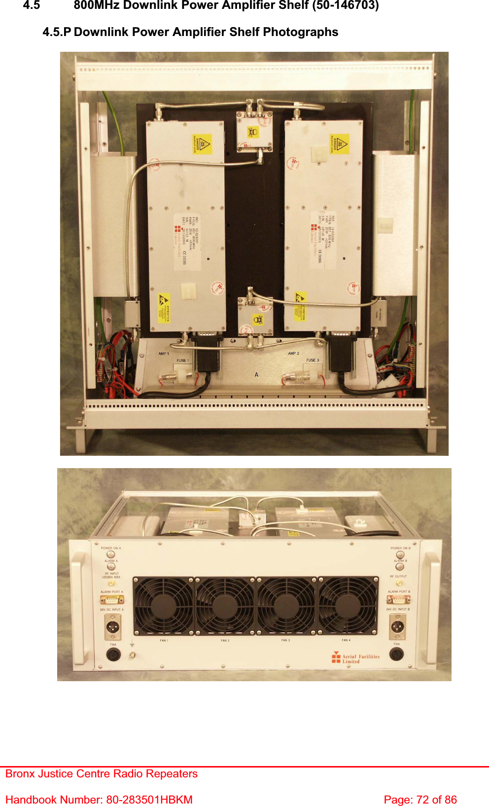
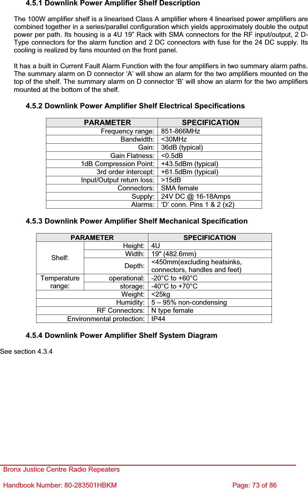
![Bronx Justice Centre Radio Repeaters Handbook Number: 80-283501HBKM Page: 74 of 86 4.5.5 Downlink Power Amplifier Shelf Parts List AFL Part Nǀ.Part Description Qty.05-002602 900MHz SPLITTER/COMBINER, 20W 6 05-002622 SPLITTER/COMBINER AUX. MTG PLATE 6 12-023301 PA 851-866MHz 20W LINEARIZED +24V 4 80-008902 24V RELAY PCB ASSEMBLY **NO LED** 2 80-245121 CLASS A LINEARIZED HEATSINK 2 80-245122 100WTETRA LINEARIZED H'SINK MTG BKT 2 80-245123 100WTETRA LINEARIZED SIDE PANEL 2 80-245124 100WTETRA LINEARIZED RACK LID 2 80-245125 100WTETRA LINEARIZED FRONT PANEL 1 80-245126 100WTETRA LINEARIZED DUCT END PLATE 2 80-245128 100WTETRA LINEARIZED DUCT MTG BLOCK 4 80-245129 100WTETRA LINEARIZED LID MTG BKT 4 80-245130 100WTETRA LINEARIZED DUCT TOP COVER 1 80-245131 100WTETRA LINEARIZED DUCT BOT COVER 1 80-245132 CLASS A LINEARIZED AMP CABLE TIDY 2 90-010021 RF CABLE SUPFLEX SMA R/A MALE 100mm 4 90-010024 RF CABLE SUPFLEX SMA R/A MALE 400mm 2 90-010026 RF CABLE SUPFLEX SMA R/A MALE 150mm 6 90-010027 RF CABLE SUPFLEX SMA R/A MALE 250mm 2 91-130005 SMA BULKHEAD ADAPTOR F/F 2 91-500001 POWER PLG 3 PIN PNL.MOUNT NC-X 2 91-600015 'D' 9 WAY PLUG S/B (NON FILTERED) 2 91-600019 'D'15 WAY SHELL (2W7) 4 91-640004 LARGE PIN FOR 91-660001 D SOCKET 8 91-660001 2W5 MIXED D TYPE SOCKET (7 WAY) 4 91-700017 ICD 15 WAY 0.1' CONNECTOR 2 91-700036 MISC 3 WAY PLUG HOUSING 4 91-700037 MISC 4 WAY PLUG HOUSING 2 91-700038 MISC PLG PIN FOR 3WAY HOUSING 14AWG 32 91-700039 MISC 3 WAY SOCKET HOUSING 6 91-700040 MISC 4 WAY SOCKET HOUSING 2 91-700042 MISC SOC.PIN FOR 3WAY HOUSING 14AWG 12 92-110003 CABLE CLIPS LARGE 13mm (WHITE) 0 92-300010 M3 x 12 HEX SPACER BRASS N:P 4 92-340001 M3 x 8mm 'D'CONNECTOR SCREW LOCK 12 92-700008 M3 BLUE RING TERMINAL % 4 92-700010 M5 BLUE RING TERMINAL 2 92-700057 FEM 2.8 x 0.8 PUSH ON BARE TERM RED 8 96-100004 32mm 20A (16A max load) FUSE HOLDER 2 96-110005 315mA FUSE GLASS A/SURGE 20 x 5mm 4 96-110015 T 15A A/SURGE FUSE 1.25' 2 96-110040 BULGIN IN-LINE FUSEHOLDER 20mm 4 96-400002 80 x 80mm 24V DC FAN SUNON 4 96-400003 PLASTIC FINGER GUARD 80 x 80mm 4 96-600003 INSULATING BOOT D.C. 2 96-700034 LED RED 5mm IP67 INTEGRAL RES. 24V 2 96-700035 LED GREEN 5mm IP67 INTEGRAL RES 24V 2 97-400002 HANDLE TYPE H6803 4U.[ALLOY] 2 97-600004 19" SUBRACK REAR RAIL 2 97-600005 19" SUBRACK FRONT RAIL 2 97-600008 19" SUBRACK TAPPED STRIP 2 97-600016 19" 4U SUBRACK MOUNTING FLANGE 2](https://usermanual.wiki/PBE-Europe-as-Axell-Wireless/50-1465SERIES.User-Manual-2-of-2/User-Guide-754700-Page-31.png)
![Bronx Justice Centre Radio Repeaters Handbook Number: 80-283501HBKM Page: 85 of 86 EC Declaration of Conformity In accordance with BS EN ISO/IEC 17050-1&-2:2004 Aerial Facilities Limited Aerial House Asheridge Road CheshamBuckinghamshire HP5 2QD United Kingdom DECLARES, UNDER OUR SOLE RESPONSIBILITY THAT THE FOLLOWING PRODUCT: PRODUCT PART NO[S]: 50-146501, 50-146601, 50-146701 PRODUCT DESCRIPTION: Radio Repeater Equipment IN ACCORDANCE WITH THE FOLLOWING DIRECTIVES: 1999/5/EC The Radio & Telecommunications Terminal Equipment Directive Annex V and its amending directives HAS BEEN DESIGNED AND MANUFACTURED TO THE FOLLOWING STANDARD[S] OR OTHER NORMATIVE DOCUMENT[S]: BS EN 60950 Information technology equipment. Safety. General requirements ETS EN 301 489-1 EMC standard for radio equipment and services. Part 1. Common technical requirements I hereby declare that the equipment named above has been designed to comply with the relevant sections of the above referenced specifications. The unit complies with all essential requirements of the Directives. SIGNEDB S BARTON TECHNICAL DIRECTOR DATE: 12/01/2007 Registered Office: Aerial House, Asheridge Road, Chesham, Buckinghamshire, HP5 2QD England Registered No. 4042808 (England) www.aerialfacilities.com](https://usermanual.wiki/PBE-Europe-as-Axell-Wireless/50-1465SERIES.User-Manual-2-of-2/User-Guide-754700-Page-42.png)