Packet Power EG4 Wireless Ethernet Gateway User Manual Eg4 Manual
Packet Power Wireless Ethernet Gateway Eg4 Manual
Manual
Wi
r
r
eless Pac
k
Ether
n
Use
V
Pac
k
271
6
Minne
1-
8
Email: in
f
www.
p
k
et Po
w
n
et Ga
t
r’s Ma
n
ersion 1
.
k
et Power,
6
Summer S
apolis, MN
5
8
77-560-8
7
f
o@packetp
o
p
acketpow
e
w
er™
t
eway
V
n
ual
.
1
,
LLC
S
t. NE
5
5413
7
70
o
wer.com
e
r.com
V
ersio
n
n
4

NOTES
Read all instructions carefully prior to installation.
No field-serviceable parts. Do not attempt to disassemble the
product as potentially severe electrical shock may result.
Installation and maintenance must be performed by qualified
personnel.
Follow basic safety precautions to reduce the risk of electrical
shock and damage to equipment.
Store in a clean, dry location. Clean with a dry cloth. Intended
for indoor use only, do not install in a wet location. Adhere to
all local electrical codes and guidelines.

P5C
PACKETPOWER. CO
M
SEE
MANUAL
FCC ID:
WCGP5C
I
MADE
INUSA
PACKETPOWER. CO
M
SEE
MANUAL
FCC ID:
WCGP5C
I
MADE
INUSA
RE
G
This
p
Clas
s
Secti
o
devi
c
interf
e
frequ
com
m
Secti
o
cond
i
interf
e
Purs
u
LLC
m
Purs
u
Indu
s
This
d
(1) T
h
unde
s
Und
e
gain
a
its g
a
com
m
Per
s
Indu
s
Le p
r
est a
u
acce
p
Conf
o
d'un
g
radio
é
ipoo
s
satis
f
P5C
M
C: 8751A
P5C
M
C: 8751A
P5C
G
ULATORY
I
p
roduct has been
s
B Device State
o
n 15.105(a) of t
h
c
e, pursuant to pa
e
rence when the
ency energy and,
m
unications.
o
n 15.19 of the F
C
i
tions: (1) This de
v
e
rence that may
c
u
ant to Part 15.21
m
ight cause har
m
u
ant to part 2.109
s
try Canada (IC)
d
evice complies
w
h
is device may n
o
s
ired operation o
f
e
r Industry Canad
a
a
pproved for the
t
a
in should be so c
m
unication.
s
ection RSS-102,
s
trie Canada (IC
)
r
ésent appareil es
u
torisée aux deu
x
p
ter tout brouillag
e
o
rmément à la ré
g
g
ain maximal (ou
é
lectrique à l'inte
n
s
otrope rayonnée
f
aisante.
I
NFORMATI
O
certified to meet
ment / FCC Reg
u
h
e FCC Rules: Th
r
t 15 of the FCC
R
equipment is ope
if not installed a
n
C
C Rules: This d
e
v
ice may not cau
s
c
ause undesired
o
of the FCC Rule
s
m
ful interference a
1c of the FCC rul
e
Compliance Sta
w
ith Industry Can
a
o
t cause interfere
n
f
the device.
a
regulations, thi
s
t
ransmitter by Ind
u
hosen that the e
q
2.5 of Industry C
a
)
Déclaration de
c
t
conforme aux C
x
conditions suiva
n
e
radioélectrique
s
g
lementation d'In
d
inférieur) approu
v
n
tion des autres
u
équivalente (p.i.r.
O
N
the following req
u
u
lations:
is equipment has
R
ules. These limi
rated in a comm
e
n
d used in accord
a
e
vice complies wi
t
s
e harmful interfe
r
o
peration.
s
, any changes o
r
nd void the FCC
a
e
s device is cate
g
tement
a
da license-exem
n
ce, and (2) this
d
s
radio transmitter
u
stry Canada. To
q
uivalent isotropic
a
a
nada regulations
c
onformité
NR d'Industrie C
a
n
tes : (1) l'appare
s
ubi, même si le
b
d
ustrie Canada, l
e
v
é pour l'émetteu
r
u
tilisateurs, il faut
c
e.) ne dépasse p
a
u
irements:
been tested and
ts are designed t
o
e
rcial environmen
t
a
nce with the inst
t
h part 15 of the
F
r
ence, and (2) thi
s
r
modifications to
a
uthorization to o
p
g
orically excluded
p
t RSS standard(
d
evice must acce
p
may only operat
e
reduce potential
a
lly radiated pow
e
, this device is ca
a
nada applicable
s
il ne doit pas pro
d
b
rouillage est sus
e
présent émetteu
r
par Industrie Ca
n
c
hoisir le type d'a
a
s l'intensité néc
e
found to comply
w
o
provide reason
a
t
. This equipmen
t
t
ruction manual,
m
F
CC Rules. Oper
a
s
device must ac
c
this product not
e
p
erate this produ
c
from routine RF
E
s). Operation is s
p
t any interferenc
e
e
using an antenn
radio interfe
r
enc
e
e
r (e.i.r.p.) is not
m
tegorically exclu
d
s
aux appareils ra
d
d
uire de brouillag
e
ceptible d'en co
m
u
r radio peut fonct
nada. Dans le bu
t
ntenne et son ga
i
e
ssaire à l'établis
s
w
ith the limits for
a
a
ble protection ag
t
generates, uses
m
ay cause harmf
u
a
tion is subject to
c
ept any interfere
n
e
xpressly approv
e
c
t.
Exposure regulat
i
ubject to the follo
w
e
, including interf
e
n
a of a type and
m
e
to other users, t
h
m
ore than that ne
d
ed from Routine
E
d
io exempts de li
c
e
, et (2) l'utilisate
u
m
promettre le fon
c
t
ionner avec une
a
t
de réduire les ri
s
i
n de sorte que la
s
ement d'une co
m
a
Class B digital
ainst harmful
, and can radiate
u
l interference to
r
the following two
n
ce received, incl
u
e
d by Packet Pow
e
i
ons.
w
ing two conditio
n
e
rence that ma
y
c
m
aximum (or less
e
h
e antenna type
a
cessary for succ
e
E
valuation Limits
.
c
ence. L'exploitat
i
u
r de l'appareil d
o
c
tionnement.
a
ntenne d'un typ
e
s
ques de brouilla
g
puissance
m
munication
radio
r
adio
u
ding
e
r
n
s:
c
ause
e
r)
a
nd
e
ssful
.
i
on
o
it
e
et
g
e

Packet Power™ Wireless DC Monitoring System Manual
Copyright 2016 © Packet Power, LLC. 2
Contents
Contents ................................................................................................................................... 2
System Overview ...................................................................................................................... 3
Device Setup ........................................................................................................................ 4
System Components ............................................................ Error! Bookmark not defined.
Wireless Current Monitors ................................................ Error! Bookmark not defined.
Menu and Navigation ............................................................................................................ 5
Setting and IP Address ......................................................................................................... 5
Gateway Placement and Mounting Bracket ................................................................. 6
Device Placement ............................................................................................................. 6
Gateway Placement .......................................................................................................... 6
Communications ................................................................................................................... 7
MODULE IDENTIFICATION ............................................................................................. 8
Technical Specifications ........................................................................................................... 9

Packet Power™ Wireless DC Monitoring System Manual
Copyright 2016 © Packet Power, LLC. 3
System Overview
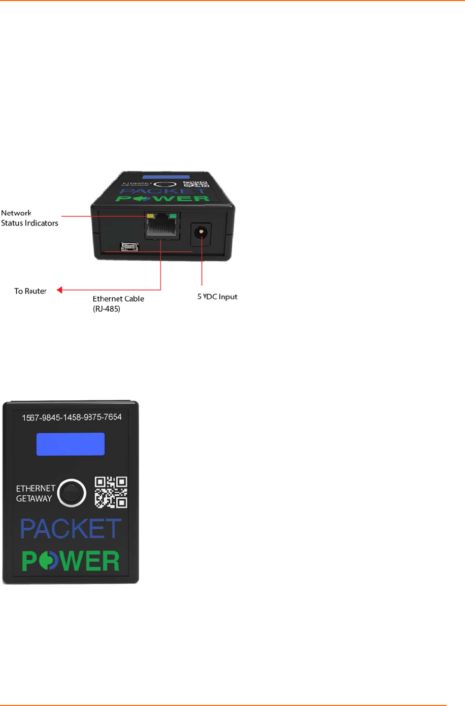
The Ethernet Gateway version 4 is the central Gateway by which all Packet Power
monitoring nodes (environmental and power) communicate. This guide is intended to provide
a high level overview of how to commission a Gateway module. Refer to the support section
of www.packetpower.com for additional support.
Gateway Types: There are various Gateway models. These include the standard Gateway
designed to communicate exclusively with the Packet Power EMX portal, Modbus TCP/IP
output versions (enterprise and solo), and SMNP output versions (solo and enterprise). All
Gateway versions can communicate with the EMX portal simultaneously (i.e. a Modbus
version can provide ModBus TCP/IP output as well as communicate with the EMX portal
simultaneously).
Gateway Models
Part Number SNMP Modbus
TCP/IP Usage
GW03-0000 No No
Use with Packet Power EMX software (local
or cloud)
GW03-00SS Yes No
SNMP Solo: single-gateway deployments of
300 monitoring units or less
GW03-00SE Yes No SNMP Enterprise: multi-gateway sites.
GW03-00MS No Yes
Modbus Solo: single-gateway deployments of
300 monitoring units or less
GW03-00ME No Yes
All models can concurrently send data to EMX
(local or cloud) if desired.
AllmodelssupportVirtualIPaddressesandcan concurrentlysenddatatoEMX(localorcloud)if
desired.
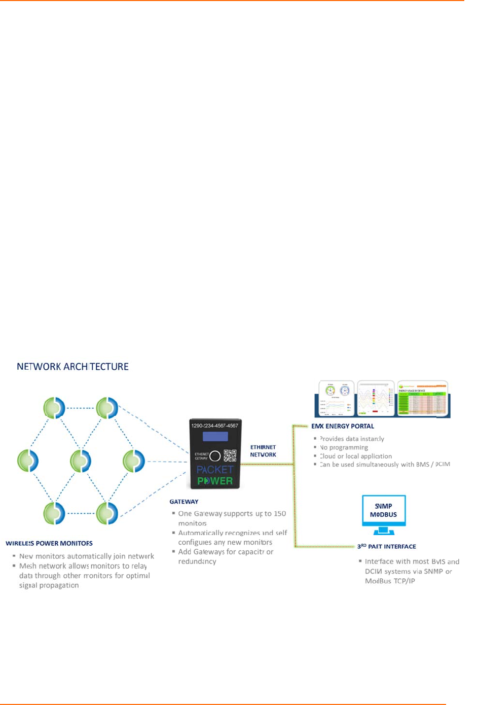
Gateway Facts: One Gateway can support up to 150 nodes (node count will affect polling
time). The network is self-configuring and will auto recognize new nodes added. Multiple
Gateways can be used within a network for capacity or redundancy and will automatically
load balance the nodes.
Updates: The Gateway firmware is capable of being remotely updated over the network.
Consult the support section of the website for additional details.
Security: The Packet Power network is designed to be the most secure monitoring system
available with many inherent security features exclusive to the architecture that limit any
possibility of penetration through the wireless nodes onto the host network. Additionally the
Gateway can be equipped with 128 bit encryption. Contact Packet Power for additional
details.
Copyri
De
v
Conn
e
the Et
Conn
e
The
G
PoE
s
Once
found
DHC
P
ght 2016 ©
P
v
ice Set
u
e
ct the Gate
hernet port
o
e
ct the pow
e
G
ateway can
s
ource.
energized t
h
on the top l
a
P
mode); no
t
192.168.
1
P
acket Power
,
u
p
way to a ro
u
o
n the back
e
r supply pr
o
be powere
d
h
e Gateway
a
bel of the
G
t
e that the I
P
1
2
Pack
e
,
LLC.
u
ter (using
a
of the Gate
w
o
vided or an
d
using PoE
will indicat
e
G
ateway) fol
P
address m
e
t Power™
W
a
standard n
e
w
ay.
y 5 VDC so
u
(Power ov
e
e
it’s firmwar
e
lowed the I
P
ay take up t
o
W
ireless DC
M
e
twork cabl
e
u
rce to the
D
e
r Ethernet)
u
r
e version, t
h
P
address (
m
o two minut
e
M
onitoring Sy
s
e
) with netw
o
D
C input of
t
using a spli
t
h
en device I
D
m
ay be blan
k
e
s to displa
y
s
tem Manua
l
o
rk access
u
t
he Gatewa
y
t
ter and 5V
D
D
number (
a
k
if operatin
g
y
.
4
u
sing
y
.
D
C
a
lso
g

Copyri
Gat
e
Me
n
To ac
c
hold t
h
devic
e
move
push
t
Set
t
To co
n
“selec
t
the [->
DHCP
click a
n
addre
s
the bu
t
you c
a
button
See
M
To pr
o
also
b
descri
imple
m
will s
h
To le
a
“Exit”.
You c
a
map,
a
ght 2016 ©
P
e
way In
t
n
u and
N
c
ess the m
e
h
e selector
b
e
for three s
e
the joystick
t
o enter a s
e
t
ing an
d
n
figure the IP
t
ion button” f
o
Set IP] optio
:Off. Click a
n
n
d hold DHC
P
s
s will appea
r
t
ton to chang
a
n exit the IP
a
when the ba
c
M
enu Map fi
o
perly confi
g
b
e entered.
T
bed above.
m
ent your c
h
h
ow on the d
a
ve the conf
i
a
n find addi
t
a
t www.pac
k
P
acket Power
,
t
erface
N
avigati
o
e
nu for the
G
b
utton / joys
t
e
conds. To
in a corres
p
e
lection.
IP Add
r
address of t
h
o
r three seco
n
n appears. C
n
d hold the b
u
P
:Off. The di
s
r
. Use short c
l
e
the underli
n
a
ddress con
s
c
k arrow cha
r
le for detai
l
g
ure the IP
a
T
o change t
h
After the
D
h
anges. Do
t
isplay while
guration m
e
t
ional infor
m
k
etpower.co
Pack
e
,
LLC.
o
n
G
ateway, pr
e
t
ick on the f
r
navigate th
e
p
onding dire
c
r
ess
h
e Gateway,
e
n
ds. Use sh
o
lick and hold
u
tton to toggl
e
s
play will the
n
l
icks to scroll
n
ed number
o
s
ole by adva
n
r
acter <- is hi
g
l
s.
a
ddress, the
h
ese param
e
D
NS Server
a
t
his by pres
s
the unit re
b
e
nu without
h
m
ation, inclu
d
m/support.
e
t Power™
W
e
ss and
r
ont of the
e
menu,
c
tion and
e
nter the set
u
o
rt clicks of th
e
[-> Set IP].
T
e
between D
H
n
show CP:
O
through spe
c
o
f the IP addr
e
cing to the e
n
g
hlighted.
Gateway,
N
e
ters use th
e
a
ddress is s
s
ing HOLD
w
b
oots and im
h
aving chan
g
d
ing details
o
W
ireless DC
M
u
p menu by p
e button to a
d
The LCD will
H
CP on and
o
O
ff <- . Click
a
c
ific digits of t
e
ss. Once th
e
n
d of the scr
e
N
etmask an
d
e
same me
n
s
et you will
n
w
hen “Reb
o
plements y
o
ges take ef
f
o
n the SNM
M
onitoring Sy
s
ressing and
h
d
vance throu
g
show DHCP
o
ff. To set a
s
a
nd hold the
b
t
he IP addres
e
correct IP
a
e
en and holdi
n
d
DNS serv
e
n
u navigatio
n
n
eed to rebo
o
o
ot” is displa
y
o
ur changes
f
ect, click an
P MIB and
M
s
tem Manua
l
h
olding the
g
h the menu
:On -or-
s
tatic IP addr
b
utton and th
s. Click and
a
ddress is en
t
n
g the select
o
e
r address
m
n
style as
ot to have
y
ed. “Booti
n
.
d HOLD th
e
M
odbus regi
5
until
r
ess
e IP
hold
t
ered
o
r
m
ust
n
g”
e
ster

Copyri
Gat
e
The
G
place
m
away
be se
c
adhe
s
Devi
c
Gate
w
ght 2016 ©
P
e
way Pl
a
G
ateway mo
u
m
ent of Gat
e
f
rom metalli
c
c
ured to mo
u
s
ive tabs pr
o
c
e Placeme
n
Never insi
d
Ideally wit
h
module)
2-4” (5-10
platform (
u
Higher is
b
allows an
u
w
ay Place
m
Gateway
m
nodes (id
e
Locate th
e
Use the s
a
cabinets o
Use the G
a
Redundan
One Gate
w
Gateways
P
acket Power
,
a
ceme
n
u
nting brac
k
e
way and E
n
c
surfaces
a
u
nting struc
t
o
vided.
n
t
d
e of a met
a
h
-in 30-100
f
cm) away f
r
u
se the mou
b
etter; alwa
y
u
nobstructe
d
ent
m
odule(s) s
h
e
ally line of
s
e
gateway a
t
a
me guideli
n
r directly on
a
teway mo
u
t Gateways
w
ay can su
p
will improv
e
Pack
e
,
LLC.
n
t and M
k
et is design
e
n
vironment
a
a
nd optimiz
e
t
ures using
b
a
l structure
(
f
eet of anot
h
r
om a large
m
nting brack
e
y
s try and lo
c
d
path to an
h
ould be loc
a
s
ite).
t
a height a
b
n
es noted in
metal surfa
u
nting brack
e
are advise
d
p
port up to 3
e
polling sp
e
e
t Power™
W
ountin
g
e
d to allow
o
a
l Monitor m
o
e
signal stre
n
b
olts, screw
s
(
exterior of t
h
h
er Packet
P
m
etallic sur
f
e
t for optima
c
ate the mo
n
other monit
o
a
ted 10-30
m
b
ove monito
r
device plac
e
ces)
e
t for optim
a
d
for any crit
i
00 Packet
P
e
eds
W
ireless DC
M
g
Brack
e
o
ptimal
o
dules
n
gth. It can
s
or
h
e rack)
P
ower devic
e
f
ace or mou
n
l placement
n
itoring nod
e
o
ring node
o
m
eters from
r
ing nodes
w
e
ment (do
n
a
l placemen
t
i
cal environ
m
P
ower monit
o
M
onitoring Sy
s
e
t
e
(gateway
o
n
ted on a n
o
e
at the hig
h
o
r gateway
one or mor
e
w
hen possib
l
n
ot locate in
s
t
and signal
m
ent
o
ring devic
e
s
tem Manua
l
o
r monitorin
o
n-metallic
h
est point th
a
e
monitorin
g
l
e
s
ide metalli
c
strength
e
s; additiona
6
g
a
t
g
c
a
l
Copyri
Figu
re
Co
m
Infor
m
netw
o
netw
o
the G
a
varie
s
Typic
a
will n
o
such
a
Every
comp
a
trans
m
Wirel
e
can c
o
in the
reach
The r
a
on th
e
of 10
0
secon
new
G
every
ght 2016 ©
P
re
21: Packet
P
m
munic
a
m
ation gathe
o
rk operatin
g
o
rk must be
w
a
teway) in t
h
s
depending
a
lly, each d
e
o
t transmit e
f
a
s fully encl
o
site where
a
a
tible Pack
e
m
ission to a
p
e
ss DC Mon
o
mmunicate
network ca
n
the Gatew
a
a
te at which
e
ratio of the
0
monitors p
e
ds. The sy
s
G
ateways or
150 Wirele
s
P
acket Power
,
P
ower Commu
n
a
tions
red by the
W
g
at 2.4 GHz
w
ithin range
h
e network.
on several
f
e
vice has an
f
fectively if i
t
o
sed metalli
c
a
Wireless
D
e
t Power Ga
t
p
proved mo
n
itors to com
m
with at lea
s
n
also com
m
a
y.
power mon
i
number of
m
e
r Gateway,
s
tem will au
t
devices ar
e
s
s DC Monit
o
Pack
e
,
LLC.
n
ications Archi
t
W
ireless DC
. The netwo
of at least
o
The effecti
v
f
actors, incl
u
effective ra
t
is installed
c
enclosure
s
D
C Monitor i
s
t
eway and
a
n
itoring and
m
unicate di
r
s
t one other
m
unicate wit
h
i
toring infor
m
m
onitors to
t
a Gateway
t
omatically r
e
e
added. Id
e
o
rs reportin
g
e
t Power™
W
t
ecture
Monitors is
rk operates
o
ne other d
e
v
e range of
t
u
ding the en
v
nge of 10 t
o
in an enclo
s
s
.
s
deployed
m
ssociated s
o
analysis ap
p
r
ectly with t
h
monitor in a
h
the Gatew
a
m
ation is ga
t
t
he number
o
should rea
d
e
allocate n
e
e
ally one Ga
g
to the Gat
e
W
ireless DC
M
transmitted
in a mesh t
o
e
vice (either
t
he radio in
t
v
ironment i
n
o
30 meters.
s
ure that en
t
m
ust have i
n
o
ftware to c
o
plications. I
h
e Gateway.
sequential
r
a
y, informat
t
hered from
of gateway
s
d
from each
e
twork traffi
c
a
teway shall
e
way.
M
onitoring Sy
s
via a Pack
e
o
pology. E
a
another mo
t
he Wireles
s
n
which the
p
The Wirel
e
t
irely blocks
n
stalled at l
e
o
llect data
a
t is not nec
e
.
As long a
s
relay mode,
ion from all
a cable dep
s
. As an ex
a
cable every
c
across Gat
e
be used for
s
tem Manua
l
e
t Power rad
a
ch device i
n
nitoring nod
s
DC Monito
p
roduct is u
s
e
ss DC Mo
n
radio signa
l
e
ast one
a
nd prepare
e
ssary for al
l
s
each moni
t
and one m
o
monitors wil
ends prima
r
a
mple, at a
y
5 to 15
e
ways whe
n
a maximu
m
7
io
n
the
e or
rs
s
ed.
n
itors
ls
it for
l
t
o
r
o
nito
r
l
r
ily
ratio
n
m
of
Copyri
MOD
U
Each
code
w
to sa
v
ght 2016 ©
P
U
LE IDENTI
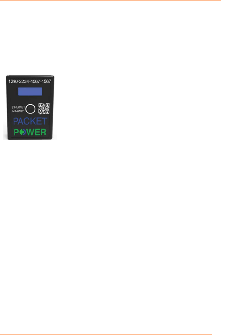
monitor is a
s
w
hich can b
e
v
e the modul
P
acket Power
,
FICATION
s
signed a s
p
e
seen on t
h
e identificat
i
Pack
e
,
LLC.
p
ecific identi
h
e front of th
i
on.
e
t Power™
W
fication cod
e
e module a
s
W
ireless DC
M
e
in the for
m
s
well as a
Q
M
onitoring Sy
s
m
of a 16 di
g
Q
R code wh
i
Figure 22: GUI
D
s
tem Manua
l
g
it alpha nu
m
i
ch can be r
e
D
Identification
o
8
m
eric
e
ad
o
n a module.

Packet Power™ Wireless DC Monitoring System Manual
Copyright 2016 © Packet Power, LLC. 9
Technical Specifications
COMMUNICATIONS
Operating frequency From 860, 930MHz and 2.4 GHz (specific frequency used varies by
region)
Wireless protocol Proprietary frequency hopping, self-configuring, load-balancing mesh
network
Wired network
protocol (Gateway)
TCP/IP (one IP address needed per Gateway) with SNMP and
Modbus TCP/IP options
Firmware updates Wireless
Typical transmission
range
10 to 50 meters indoors from any one device to any other
Antenna Fully enclosed, fixed configuration
Monitoring Unit to
Gateway Ratio
From 100 to 300 monitoring units per gateway depending on desired
data collection rate and Gateway model
Gateways per site Unlimited
Multi-site support Yes
Encryption Optional 128-bit
Compatible devices All Packet Power modules may be combined in the network
OPERATING ENVIRONMENT
Operating
temperature
0° to +40° C (+32° to +104°F)
Operating humidity 10% to 90% non-condensing
Environmental rating Indoor use / NEMA 1
Mounting Typical: on top of server cabinet, under a cable raceway, under a
raised floor
DISPLAY
LCD LCD display for status and configuration details
LED Indicates general device status
SIZE AND WEIGHT
Ethernet Gateway 76mm x 94mm x 31mm; Weight: 65g (3 oz)

Packet Power™ Wireless DC Monitoring System Manual
Copyright 2016 © Packet Power, LLC. 10
POWER SUPPLY
External Power
Supply
100- 240VA/C input voltage, 50-60Hz (5 VDC output) (72mm x
43mm x 29mm)
Safety Standards EN60950 UL60950 IEC60950
Plug Types NEMA 5-15, CEE-7 Schuko, AS/NZS 3112 2000, BS 1363A, C14,
BS 546A
Power Consumption 3W
Power Over Ethernet Available. Requires an external PoE splitter
CERTIFICATIONS
Certifications FCC, Industry Canada, CE; consult Packet Power for additional
certifications