Panasonic Devices Europe 1315 Bluetooth Module User Manual PAN1315ETU design guide

Panasonic Industrial Devices Europe GmbH Bluetooth Module PAN1315ETU design guide
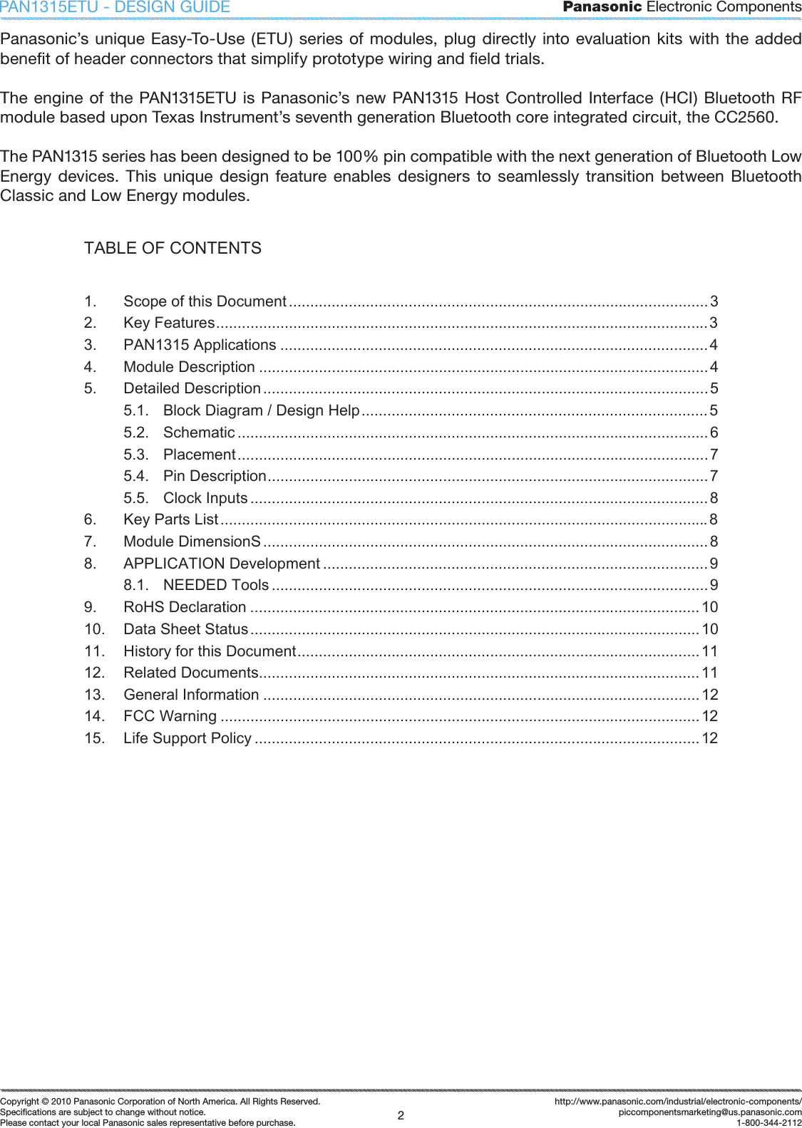
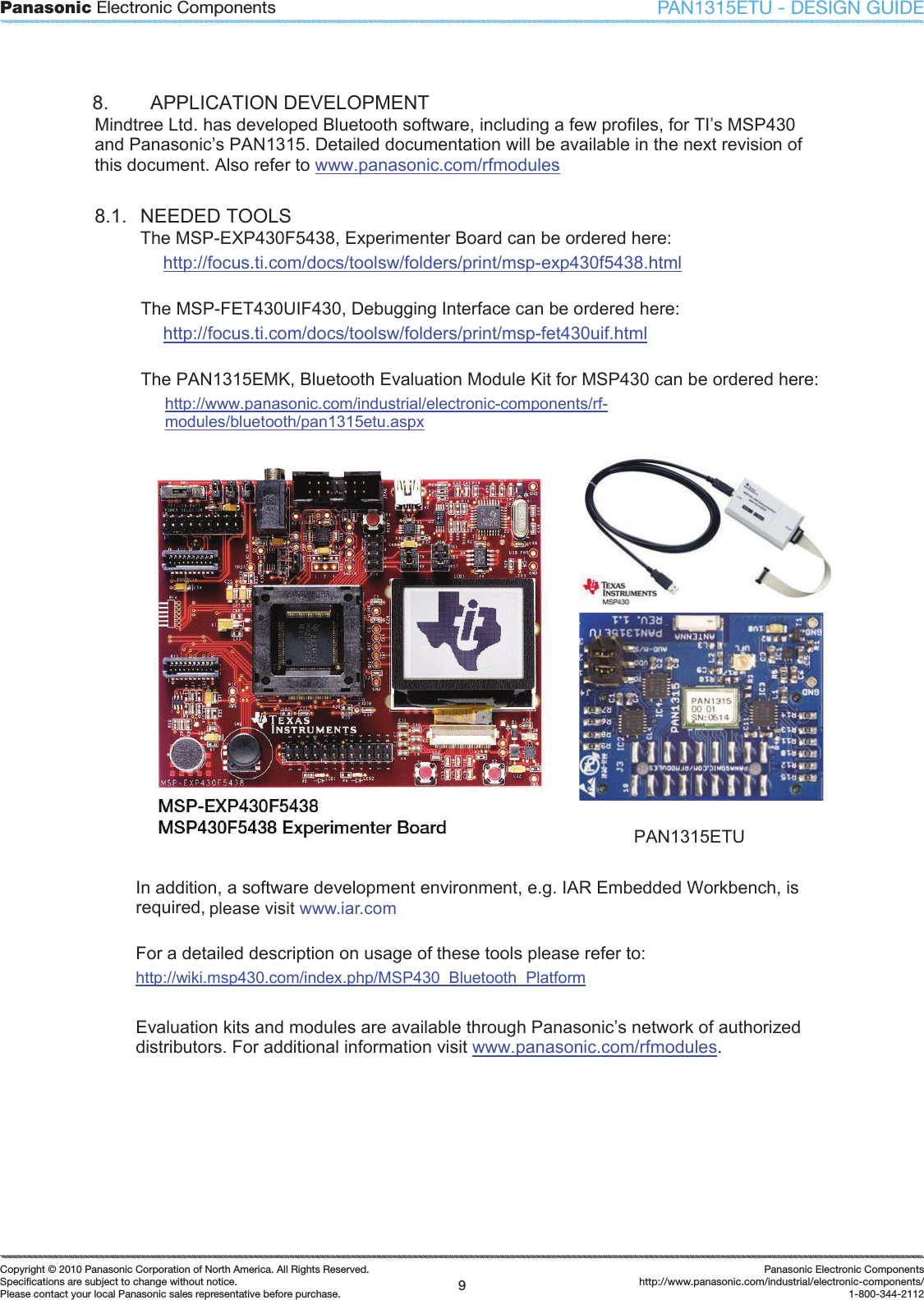
Updated OEM instruction for module integration
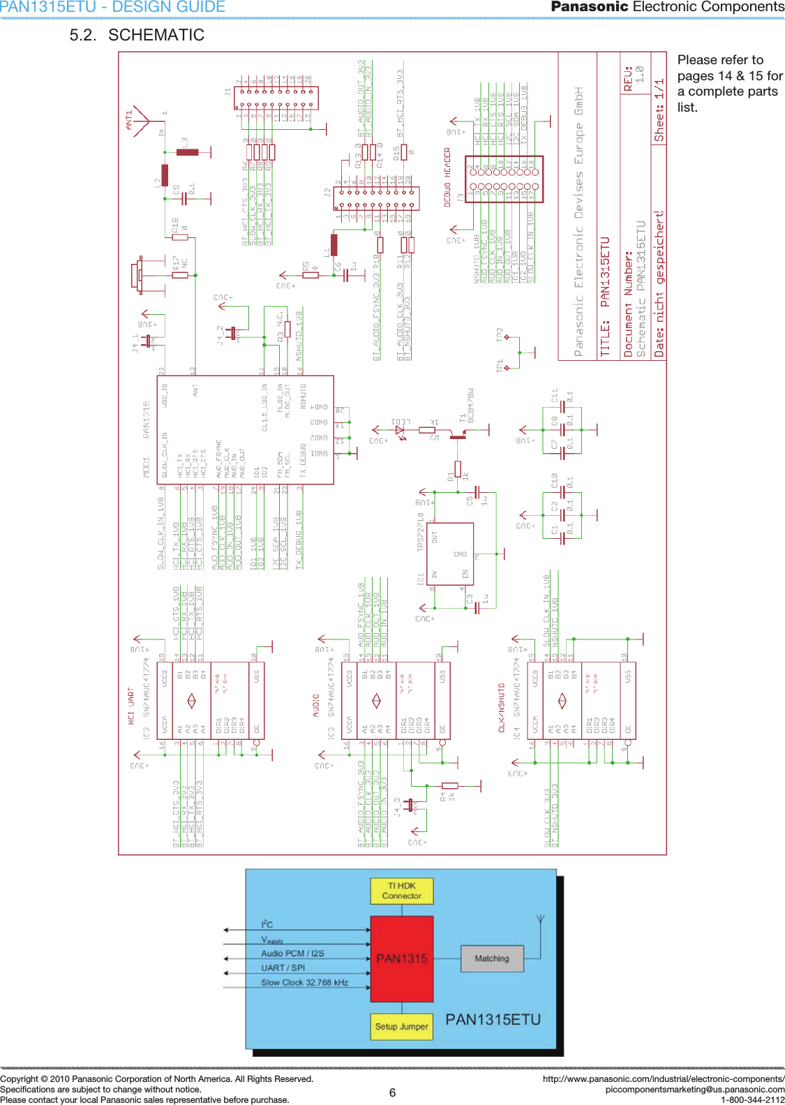
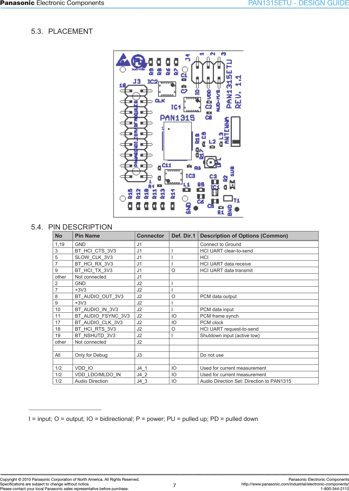
PAN1315ETU DESIGN GUIDEwww.panasonic.com/rfmodulesPOWERED BYPanasonicElectronic Components
Panasonic Electronic Components2Copyright © 2010 Panasonic Corporation of North America. All Rights Reserved.Specifi cations are subject to change without notice.Please contact your local Panasonic sales representative before purchase.http://www.panasonic.com/industrial/electronic-components/piccomponentsmarketing@us.panasonic.com1-800-344-2112PAN1315ETU - DESIGN GUIDEPanasonic’s unique Easy-To-Use (ETU) series of modules, plug directly into evaluation  kits with the  added benefi t of header connectors that simplify prototype wiring and fi eld trials.The engine of the PAN1315ETU  is Panasonic’s new PAN1315 Host Controlled Interface (HCI) Bluetooth RF module based upon Texas Instrument’s seventh generation Bluetooth core integrated circuit, the CC2560.The PAN1315 series has been designed to be 100% pin compatible with the next generation of Bluetooth Low Energy  devices.  This  unique  design  feature enables designers  to  seamlessly  transition  between  Bluetooth Classic and Low Energy modules.TABLE OF CONTENTS 1. Scope of this Document..................................................................................................32. Key Features...................................................................................................................33. PAN1315 Applications ....................................................................................................44. Module Description ......................................................................................................... 45. Detailed Description........................................................................................................55.1. Block Diagram / Design Help.................................................................................55.2. Schematic .............................................................................................................. 65.3. Placement..............................................................................................................75.4. Pin Description.......................................................................................................75.5. Clock Inputs ...........................................................................................................86. Key Parts List..................................................................................................................87. Module DimensionS ........................................................................................................88. APPLICATION Development ..........................................................................................98.1. NEEDED Tools ......................................................................................................99. RoHS Declaration .........................................................................................................1010. Data Sheet Status.........................................................................................................1011. History for this Document..............................................................................................1112. Related Documents.......................................................................................................1113. General Information ......................................................................................................1214. FCC Warning ................................................................................................................1215. Life Support Policy ........................................................................................................12
Panasonic Electronic Components3Copyright © 2010 Panasonic Corporation of North America. All Rights Reserved.Specifi cations are subject to change without notice.Please contact your local Panasonic sales representative before purchase.Panasonic Electronic Componentshttp://www.panasonic.com/industrial/electronic-components/1-800-344-2112PAN1315ETU - DESIGN GUIDE1.  SCOPE OF THIS DOCUMENT This Design Guide is intended for use with the Bluetooth development platform PAN1315ETU. (Easy To Use). This guide will help you create a design that can be implemented quickly into your product.  This guide describes the hardware and gives usefull tips. In addition, the software description can be downloaded from TI’s website.  Please refer to chapter 8 “Application Development” for a quick overview. 2.  KEY FEATURES x  Fast Time to Market x  Easy PCB Layout Using Eagle CAD Files: x  Capable of 2 Layer PCB with 0.2mm Line Width  x  Optional EEPROM for Data Configuration x  Optional -40 to +85°C Operating Temperature Range x  MindTree Ethermind Bluetooth Stack with SPP for TI MSP430 Available From TI. x  Other Profiles Available on Request x  FCC, IC and ETSE Compliant x  100%  Compatible  with  Next  Generation  PAN1315  Bluetooth  Low  Energy/Classic Module Eagle CAD Files in use
Panasonic Electronic Components4Copyright © 2010 Panasonic Corporation of North America. All Rights Reserved.Specifi cations are subject to change without notice.Please contact your local Panasonic sales representative before purchase.http://www.panasonic.com/industrial/electronic-components/piccomponentsmarketing@us.panasonic.com1-800-344-2112PAN1315ETU - DESIGN GUIDE3.  PAN1315 APPLICATIONS All Embedded Wireless Applications x  Access Points  x  Cable Replacement x  Printer Adapters  x  Personal Digital Assistants (PDAs) x  Printers  x  Access Points x  Scanners  x  Computers and Peripherals x  Wireless Sensors x  Low Power x  Industrial Control Applications x  Medical 4.  MODULE DESCRIPTION The PAN1315ETU (EasyToUse) Module is a development platform for a class 2 HCI module to implement Bluetooth functionality into various electronic devices.  The PAN1315ETU  is  intended for evaluation purpose and works with Texas Instrument’s MSP430 Hardware Development Kit. Please refer to chapter 8, APPLICATION Development. Communication between the module and the host controller is typically carried out via UART, but can also be performed through SPI with this hardware. To aide in the implementation of this reference design, Eagle formatted application and layout files are available on the web at the address below. Please contact your local sales office for further details on additional options and services, by visiting www.panasonic.com/rfmodules.www.panasonic.com/industrial/includes/pdf/PAN1315ETU_Eagle_Ver1_1.zip
Panasonic Electronic Components5Copyright © 2010 Panasonic Corporation of North America. All Rights Reserved.Specifi cations are subject to change without notice.Please contact your local Panasonic sales representative before purchase.Panasonic Electronic Componentshttp://www.panasonic.com/industrial/electronic-components/1-800-344-2112PAN1315ETU - DESIGN GUIDE5.  DETAILED DESCRIPTION 5.1.  BLOCK DIAGRAM / DESIGN HELP
Panasonic Electronic Components6Copyright © 2010 Panasonic Corporation of North America. All Rights Reserved.Specifi cations are subject to change without notice.Please contact your local Panasonic sales representative before purchase.http://www.panasonic.com/industrial/electronic-components/piccomponentsmarketing@us.panasonic.com1-800-344-2112PAN1315ETU - DESIGN GUIDEPlease refer to pages 14 & 15 for a complete parts list.5.2.  SCHEMATIC
Panasonic Electronic Components7Copyright © 2010 Panasonic Corporation of North America. All Rights Reserved.Specifi cations are subject to change without notice.Please contact your local Panasonic sales representative before purchase.Panasonic Electronic Componentshttp://www.panasonic.com/industrial/electronic-components/1-800-344-2112PAN1315ETU - DESIGN GUIDE5.3.  PLACEMENT 5.4.  PIN DESCRIPTION No Pin Name  Connector  Def. Dir.1 Description of Options (Common) 1,19  GND  J1    Connect to Ground 3  BT_HCI_CTS_3V3  J1  I  HCI UART clear-to-send 5  SLOW_CLK_3V3  J1  I  HCI 7  BT_HCI_RX_3V3  J1  I  HCI UART data receive 9  BT_HCI_TX_3V3  J1  O  HCI UART data transmit other  Not connected  J1     2  GND  J2  I   7  +3V3  J2  I   8  BT_AUDIO_OUT_3V3  J2  O  PCM data output 9  +3V3  J2  I   10  BT_AUDIO_IN_3V3  J2  I  PCM data input 11  BT_AUDIO_FSYNC_3V3  J2  IO  PCM frame synch 17  BT_AUDIO_CLK_3V3  J2  IO  PCM clock 18  BT_HCI_RTS_3V3  J2  O  HCI UART request-to-send 19  BT_NSHUTD_3V3  J2  I  Shutdown input (active low) other  Not connected  J2              All  Only for Debug  J3    Do not use          1/2  VDD_IO  J4_1  IO  Used for current measurement 1/2  VDD_LDO/MLDO_IN  J4_2  IO  Used for current measurement 1/2  Audio Direction  J4_3  IO  Audio Direction Set: Direction to PAN1315 I = input; O = output; IO = bidirectional; P = power; PU = pulled up; PD = pulled down
Panasonic Electronic Components8Copyright © 2010 Panasonic Corporation of North America. All Rights Reserved.Specifi cations are subject to change without notice.Please contact your local Panasonic sales representative before purchase.http://www.panasonic.com/industrial/electronic-components/piccomponentsmarketing@us.panasonic.com1-800-344-2112PAN1315ETU - DESIGN GUIDE5.5.  CLOCK INPUTS The slow clock is always supplied from an external source. It is connected to the SLOW_CLK_IN and can be a digital signal in the range of 0-1.8 V. The slow clock's frequency accuracy must be 32.768 kHz r250 ppm for Bluetooth usage (according to the Bluetooth specification). When the MSP430 Experimenter board is connected the signal is exposed from the Controller. So within this application there is no additional clock needed. 6.  KEY PARTS LIST Reference Designator  Partnumber  Supplier PAN1315  ENW89818C2JF  Panasonic  J1,J2  SFM-110-02-S-D-K-A  Samtec, Farnell IC1  TPS72718DSET  TI IC2,3,4  SN74AVC4T774RGYR  TI J4  Pinheader 2.54mm 6pol  Generic T1  BC847   Generic LED1  SMD LED Rot  Generic ANT1  2450AT43B100  Johanson UFL2  U.FL  Hirose 7.   MODULE DIMENSIONS No.  Item  Dimension [mm]  Tolerance [mm]  Remark 1  Width  40  r 1 2  Lenght  30  r 1 3  Height  15  r 1  With connectors
Panasonic Electronic Components9Copyright © 2010 Panasonic Corporation of North America. All Rights Reserved.Specifi cations are subject to change without notice.Please contact your local Panasonic sales representative before purchase.Panasonic Electronic Componentshttp://www.panasonic.com/industrial/electronic-components/1-800-344-2112PAN1315ETU - DESIGN GUIDE8.  APPLICATION DEVELOPMENT Mindtree Ltd. has developed Bluetooth software, including a few profiles, for TI’s MSP430 and Panasonic’s PAN1315. Detailed documentation will be available in the next revision of this document. Also refer to www.panasonic.com/rfmodules8.1.  NEEDED TOOLS The MSP-EXP430F5438, Experimenter Board can be ordered here: http://focus.ti.com/docs/toolsw/folders/print/msp-exp430f5438.html The MSP-FET430UIF430, Debugging Interface can be ordered here: http://focus.ti.com/docs/toolsw/folders/print/msp-fet430uif.html The PAN1315EMK, Bluetooth Evaluation Module Kit for MSP430 can be ordered here: http://www.panasonic.com/industrial/electronic-components/rf-modules/bluetooth/pan1315etu.aspxPAN1315ETU In addition, a software development environment, e.g. IAR Embedded Workbench, is required, please refer to 0. For a detailed description on usage of these tools please refer to: http://wiki.msp430.com/index.php/MSP430_Bluetooth_PlatformEvaluation kits and modules are available through Panasonic’s network of authorized distributors. For additional information visit www.panasonic.com/rfmodules.please visit www.iar.com
Panasonic Electronic Components10Copyright © 2010 Panasonic Corporation of North America. All Rights Reserved.Specifi cations are subject to change without notice.Please contact your local Panasonic sales representative before purchase.http://www.panasonic.com/industrial/electronic-components/piccomponentsmarketing@us.panasonic.com1-800-344-2112PAN1315ETU - DESIGN GUIDE9.  ROHS DECLARATION Declaration of environmental compatibility for supplied products: Panasonic Electronic Devices Europe GMBH hereby declares, to the best of our current knowledge, based on the declaration of our suppliers that this product does not contain the following substances which are banned by Directive 2002/95/EC (RoHS) or if contain a maximum concentration of 0.1% by weight in homogeneous materials: x  Lead and lead compounds x  Mercury and mercury compounds x  Chromium (VI) x  PBB (polybrominated biphenyl) category x  PBDE (polybrominated biphenyl ether) category And a maximum concentration of 0.01% by weight in homogeneous materials for x  Cadmium and cadmium compounds 10.  DATA SHEET STATUS This data sheet contains preliminary product specification. Panasonic reserves the right to change the specification without notice, in order to improve the design and supply the best possible product. Preliminary product specification means also that the hardware has the engineering sample (ES) status. Please consult the most recently issued data sheet before initiating or completing a design.
Panasonic Electronic Components11Copyright © 2010 Panasonic Corporation of North America. All Rights Reserved.Specifi cations are subject to change without notice.Please contact your local Panasonic sales representative before purchase.Panasonic Electronic Componentshttp://www.panasonic.com/industrial/electronic-components/1-800-344-2112PAN1315ETU - DESIGN GUIDE11.  HISTORY FOR THIS DOCUMENT Revision Version Date Datum Modification / Remarks Änderungen / Bemerkungen 0.90  24.02.2010  1st preliminary version 0.95  13.03.2010  Accept all changes from RT and added the FCC warning. Correct some formats and create a new directory 0.96  09.06.2010  Included Design Guide, BOM 12.  RELATED DOCUMENTS For an update, please visit the following website: IAR Embedded Workbench Version 3+ for MSP430 User's Guide Rev. Q, 25 Nov 2009 http://www.ti.com/lit/pdf/slau138PAN1315 Datasheet: http://www.panasonic.com/industrial/electronic-components/rf-modules/bluetooth/pan1315.aspx
Panasonic Electronic Components12Copyright © 2010 Panasonic Corporation of North America. All Rights Reserved.Specifi cations are subject to change without notice.Please contact your local Panasonic sales representative before purchase.http://www.panasonic.com/industrial/electronic-components/piccomponentsmarketing@us.panasonic.com1-800-344-2112PAN1315ETU - DESIGN GUIDE13.  GENERAL INFORMATION © Panasonic Electronic Devices Europe GmbH 2010. All rights reserved. This product description does not lodge the claim to be complete and free of mistakes. Please contact the related product manager in every case. Any  ES  samples  delivered  to  the  customer  have  the  status  Engineering  Samples.  This means,  the  design  of  this  product  is  not  yet  concluded.  Engineering  Samples  may  be partially or fully functional, and there may be differences that will be published in the most recent Data Sheet. Engineering Samples are not qualified and are not to be used for reliability testing or series production. Disclaimer:Customer  acknowledges  that  samples  may  deviate  from  the  Data  Sheet  and  may  bear defects due to their status of development and the lack of qualification mentioned above. Panasonic rejects any liability or product warranty for Engineering Samples. In particular, Panasonic disclaims liability for damages caused by x  The use of the Engineering Sample other than for Evaluation Purposes, particularly the installation or integration in an other product to be sold by Customer, x  Deviation or lapse in function of Engineering Sample, x  Improper use of Engineering Samples. Panasonic disclaimes any liability for consequential and incidental damages. In  case  of  any  questions,  please  contact  your  local  sales  partner  or  the  related  product manager. 14.  FCC WARNING This equipment is intended for use in a laboratory test environment only. It generates, uses, and can radiate radio frequency energy and has not been tested for compliance with the limits of computing devices pursuant to subpart J of part 15 of FCC rules, which are designed to provide reasonable protection against radio frequency interference. Operation of this equipment in other environments may cause interference with radio communications, in which case the user at his own expense will be required to take whatever measures may be required to correct this interference. 15.  LIFE SUPPORT POLICY This  Panasonic  product  is  not  designed  for  use  in  life  support  appliances,  devices,  or systems where malfunction can reasonably be expected to result in a significant personal injury  to the user,  or as  a  critical component in  any life support device or system  whose failure to perform can be reasonably expected to cause the failure of the life support device or  system,  or  to  affect  its  safety  or  effectiveness.  Panasonic  customers  using  or  selling these  products  for  use  in  such  applications  do  so  at  their  own  risk  and  agree  to  fully indemnify Panasonic for any damages resulting.
Panasonic Electronic Components13Copyright © 2010 Panasonic Corporation of North America. All Rights Reserved.Specifi cations are subject to change without notice.Please contact your local Panasonic sales representative before purchase.Panasonic Electronic Componentshttp://www.panasonic.com/industrial/electronic-components/1-800-344-2112PAN1315ETU - DESIGN GUIDEAPPENDIX:Test Procedure:The  PAN1315ETU  is  connected  via  the  MSP430  Board,  HCI  UART  to  PC.  The connection  to  CBT  is  made  via  the  ETU’s  Antenna  to  the  CBT  reference  antenna. Output power and current consumption is then checked.
Panasonic Electronic Components14Copyright © 2010 Panasonic Corporation of North America. All Rights Reserved.Specifi cations are subject to change without notice.Please contact your local Panasonic sales representative before purchase.http://www.panasonic.com/industrial/electronic-components/piccomponentsmarketing@us.panasonic.com1-800-344-2112PAN1315ETU - DESIGN GUIDEPARTS LIST: (Please refer to the schematic on page 6)Part Value Device Package CommentsAntennaANT1 JOH_2450AT43B100 JOH_2450AT43B100 SMD_7X2X2 Antenna 1CapacitorsC1 0.1 C-EUC0402 C0402 rclC2 0.1 C-EUC0402 C0402 rclC3 1u C-EUC0603 C0603 rclC5 1u C-EUC0603 C0603 rclC6 1u C-EUC0603 C0603 rclC7 0.1 C-EUC0402 C0402 rclC8 0.1 C-EUC0402 C0402 rclC9 2.2 pF C-EUC0402 C0402 rclC10 0.1 C-EUC0402 C0402 rclC11 0.1 C-EUC0402 C0402 rclIntegrated CircuitsIC1 TPS72718 TPS72718 DSE_S-PDS0-N6 texas 1IC2 SN74AVC4T774 SN74AVC-4T774RGY RGY SN74AVC4T774 1IC3 SN74AVC4T774 SN74AVC-4T774RGY RGY SN74AVC4T774 1IC4 SN74AVC4T774 SN74AVC-4T774RGY RGY SN74AVC4T774 1ConnectorsJ1SFM-110-02-SM-D-A-K-TRSFM-110-02_2 SFM-110-02_2  Samtec1J2SFM-110-02-SM-D-A-K-TRSFM-110-02_2 SFM-110-02_2  Samtec1J3 NC _PINHD-2X9SMD _2X09SMD pinheadJ4_1 _PINHD-2X1SMD _2X1SMD pinhead 1J4_2 _PINHD-2X1SMD _2X1SMD pinhead 1J4_3 _PINHD-2X1SMD _2X1SMD pinhead 1UFL2 U.FL U.FL U.FL hirose
Panasonic Electronic Components15Copyright © 2010 Panasonic Corporation of North America. All Rights Reserved.Specifi cations are subject to change without notice.Please contact your local Panasonic sales representative before purchase.Panasonic Electronic Componentshttp://www.panasonic.com/industrial/electronic-components/1-800-344-2112PAN1315ETU - DESIGN GUIDEPart Value Device Package CommentsInductorsL1 1Kȍ, 100mA L0603 rcl 1L2 3.6 nH L0402 rcl 1L3 Not Mounted L0402 rcl 1LEDLED1 LEDCHIPLED_0805CHI-PLED_0805  led1RF ModuleMOD1 PAN1315P1315FP_! PAN1315P1315FP_! P1315FP_1 P1315_Eagle4 1ResistorsR1 1k R-EU_R0402 R0402 rclR2 1k R-EU_R0402 R0402 rclR3 N.C. R-EU_R0402 R0402 rclR4 1k R-EU_R0402 R0402 rclR5 0 R-EU_R0603 R0603 rclR6 0 R-EU_R0603 R0603 rclR7 0 R-EU_R0603 R0603 rclR8 0 R-EU_R0603 R0603 rclR9 0 R-EU_R0603 R0603 rclR10 0 R-EU_R0603 R0603 rclR11 0 R-EU_R0603 R0603 rclR12 0 R-EU_R0603 R0603 rclR13 0 R-EU_R0603 R0603 rclR14 0 R-EU_R0603 R0603 rclR15 0 R-EU_R0603 R0603 rclR17 NC R-EU_R0402 R0402 rclR18 0 R-EU_R0402 R0402 rclOtherT1 BC847BW BC847BW SOT323 nano_JHOTP1 TPP1-10 TPP1-10 _P1-10 testpadTP2 TPP1-10 TPP1-10 _P1-10 testpad

Navigation menu