Panasonic Devices Europe 9320 Wireless LAN Embedded Module User Manual TABLE OF CONTENTS
Panasonic Industrial Devices Europe GmbH Wireless LAN Embedded Module TABLE OF CONTENTS
UserManual.wiki
>
Panasonic Devices Europe
>
9320 User Manual
15_ENW49A013EF_(PAN9320+PAN9310)_UserMan
Navigation menu
Upload a User Manual
Namespaces
Wiki Guide
HTML
PDF
Info
Views
User Manual
Discussion / Help
Navigation
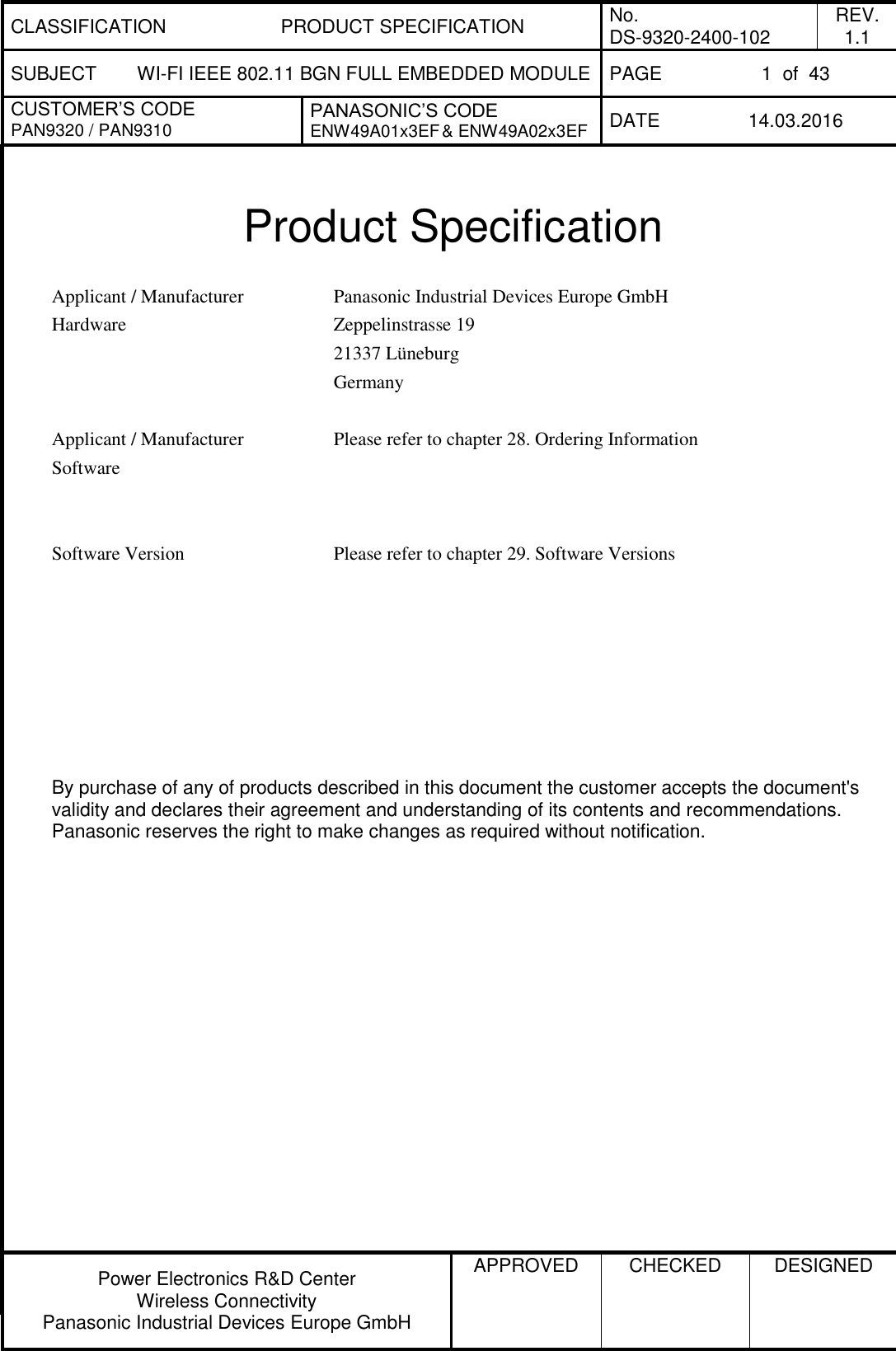
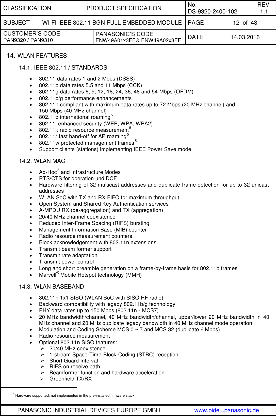
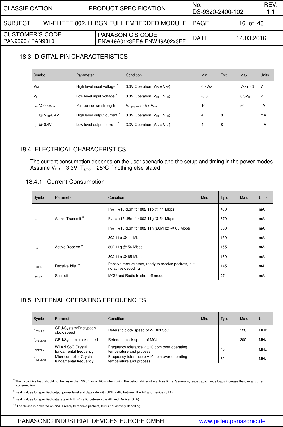
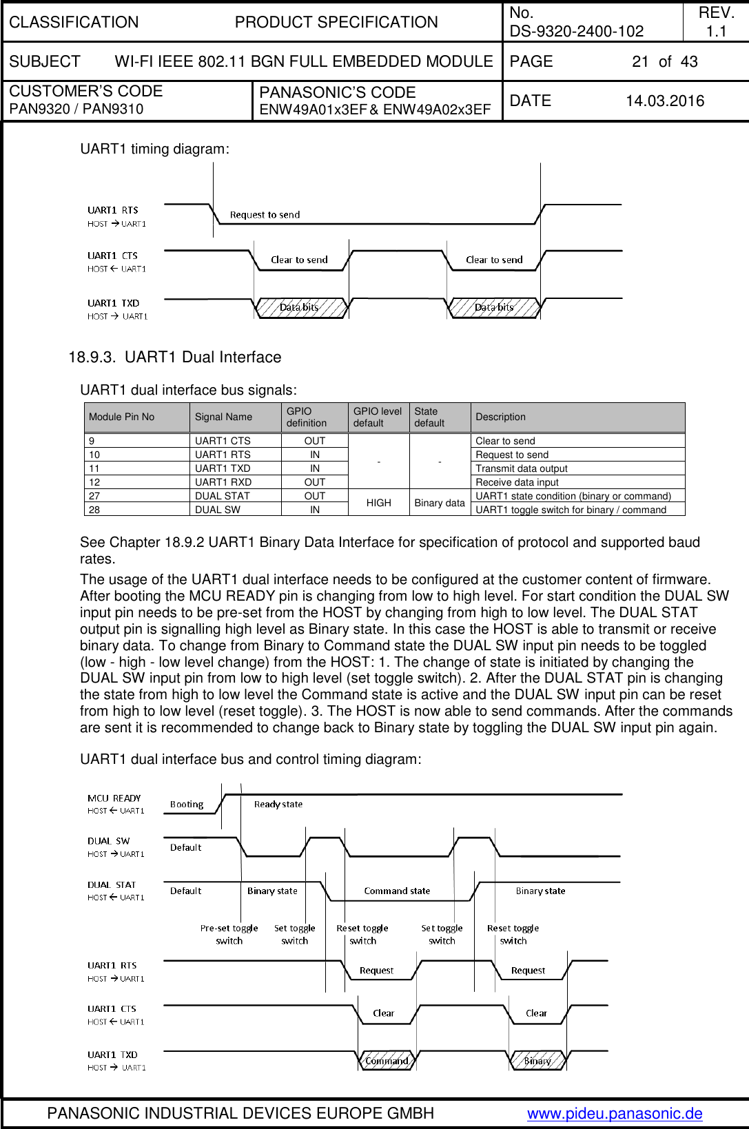
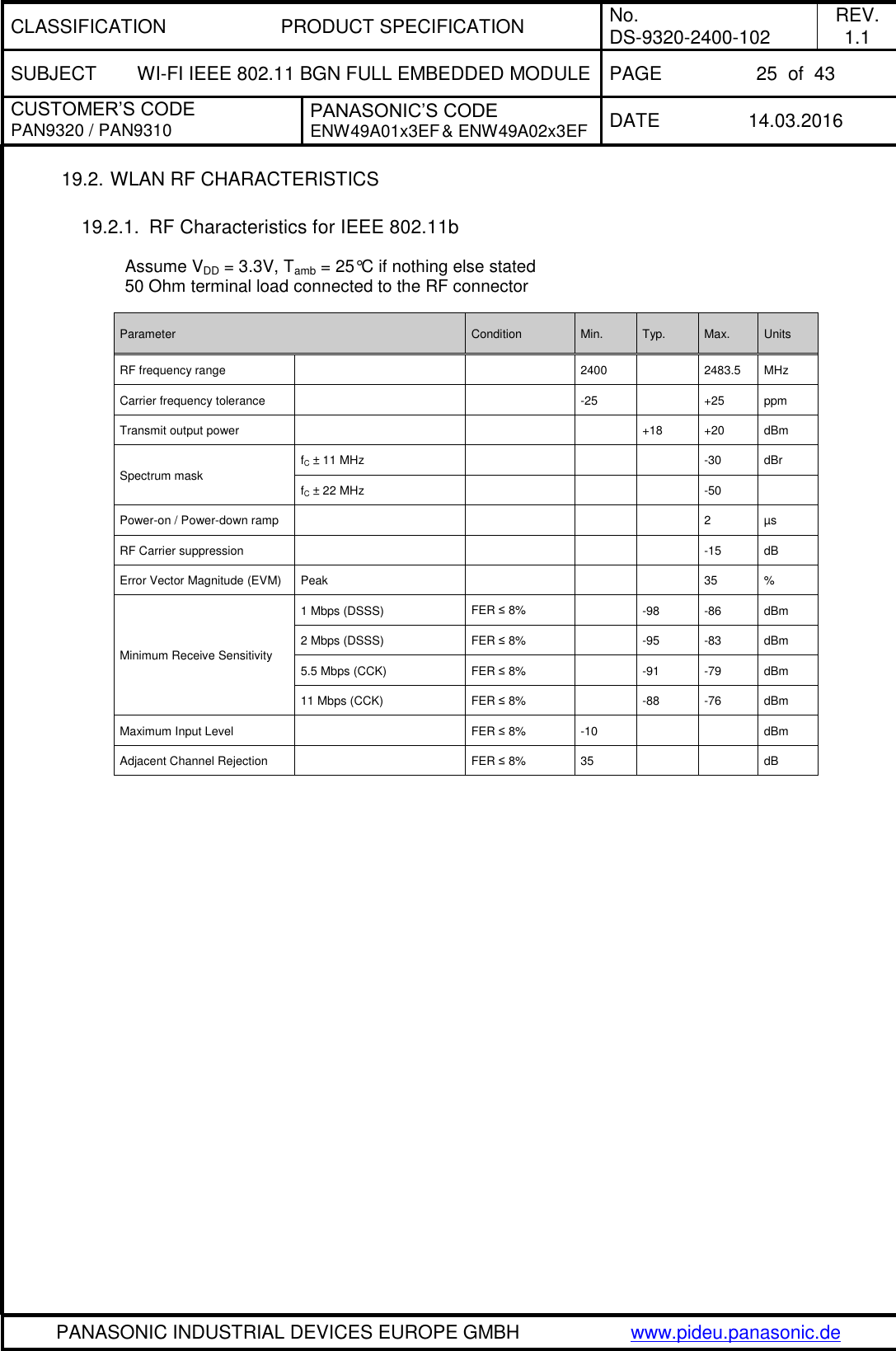
![CLASSIFICATION PRODUCT SPECIFICATION No. DS-9320-2400-102 REV. 1.1 SUBJECT WI-FI IEEE 802.11 BGN FULL EMBEDDED MODULE PAGE 5 of 43 CUSTOMER’S CODE PAN9320 / PAN9310 PANASONIC’S CODE ENW49A01x3EF & ENW49A02x3EF DATE 14.03.2016 PANASONIC INDUSTRIAL DEVICES EUROPE GMBH www.pideu.panasonic.de 1. SCOPE OF THIS DOCUMENT This product specification applies to Panasonic’s Wi-Fi IEEE 802.11 b/g/n full embedded module with brand names PAN9320 and PAN9310. 2. HISTORY FOR THIS DOCUMENT Revision Date Modification / Remarks 0.1 22.04.2015 1st preliminary version 1.0 26.11.2015 Adapt Panasonic’s Code by adding model ENW49A02x3EF Adapt information in chapter: 4 Related Documents, 5 Key Features, 7 WLAN Overview, 8 Description of the , 10 Detailed Description, 11 General Features, 15 Block Diagram, 18.9 Host Interface Specification, 19 RF Electrical Characteristics, 21 PAN9320 / PAN9310 Module Dimension, 22 PAN9320 / PAN9310 Footprint of the Module, 23 Case Marking (Example for PAN9320 – FCC Version) , and 28 Ordering Information Add chapter: 13 Peripheral Bus Interface, 18.6 Power Up Sequence, 18.7 Firmware related Timing, 29 Software Versions, and 31 Regulatory Information 1.1 14.03.2016 Adapt information in chapter 31.1.6 RF Exposure 3. DATA SHEET STATUS This data sheet contains the PRELIMINARY specification. Supplementary data will be published at a later date. Panasonic reserves the right to make changes at any time without notice. Consult the most recently issued data sheet before initiating or completing a design. 4. RELATED DOCUMENTS Search these homepages for documentation updates. [1] PAN9320 Flyer PAN9320 Download Page (Flyer) [2] PAN9320 Design Guide PAN9320 Download Page (Design Guide) [3] PAN9320 Quick Start Guide PAN9320 Download Page (Quick Start Guide) [4] PAN9320 Communication Specification PAN9320 Download Page (Communication Specification) [5] PAN9320 Application Note PAN9320 Download Page (Application Note) [6] Semiconductor Datasheet 88MC200 from Marvell® 88W8782 from Marvell® [7] Application Note Land Grid Array Land Grid Array [8] REACH and RoHS Certificate WM-REACH_and_RoHS_directive](https://usermanual.wiki/Panasonic-Devices-Europe/9320/User-Guide-2934779-Page-5.png)
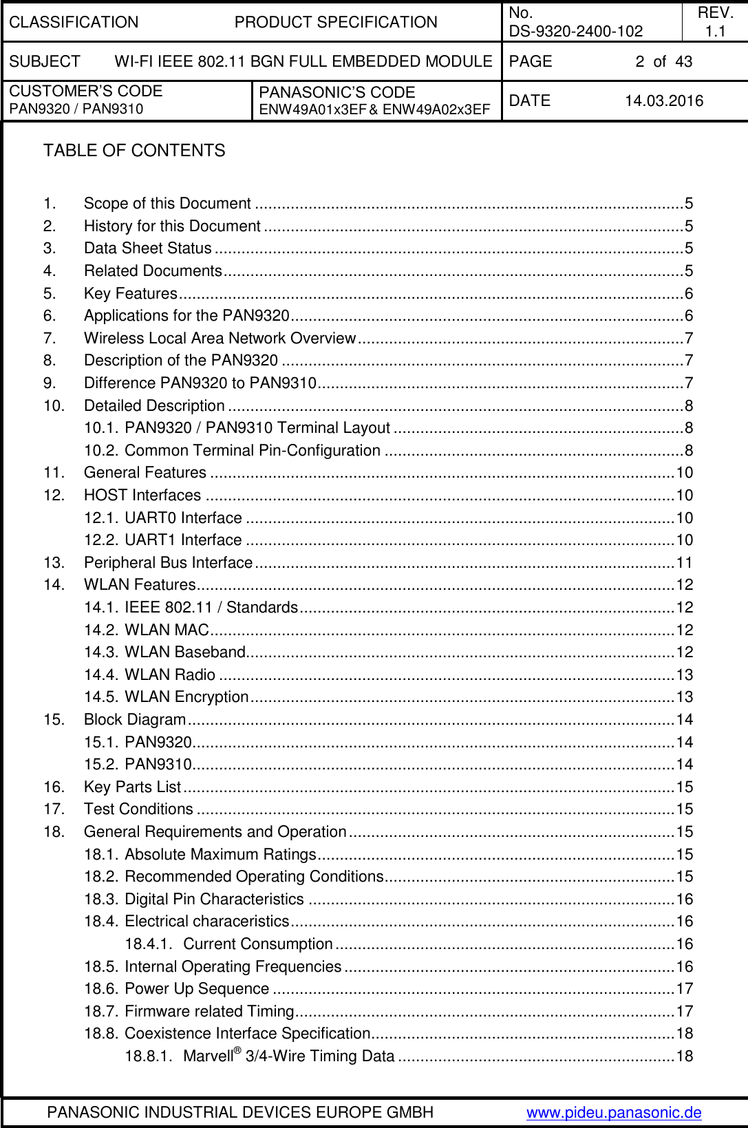
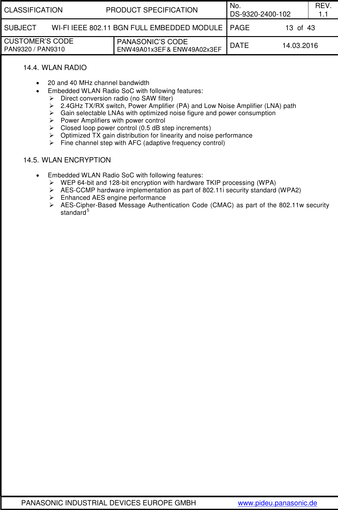
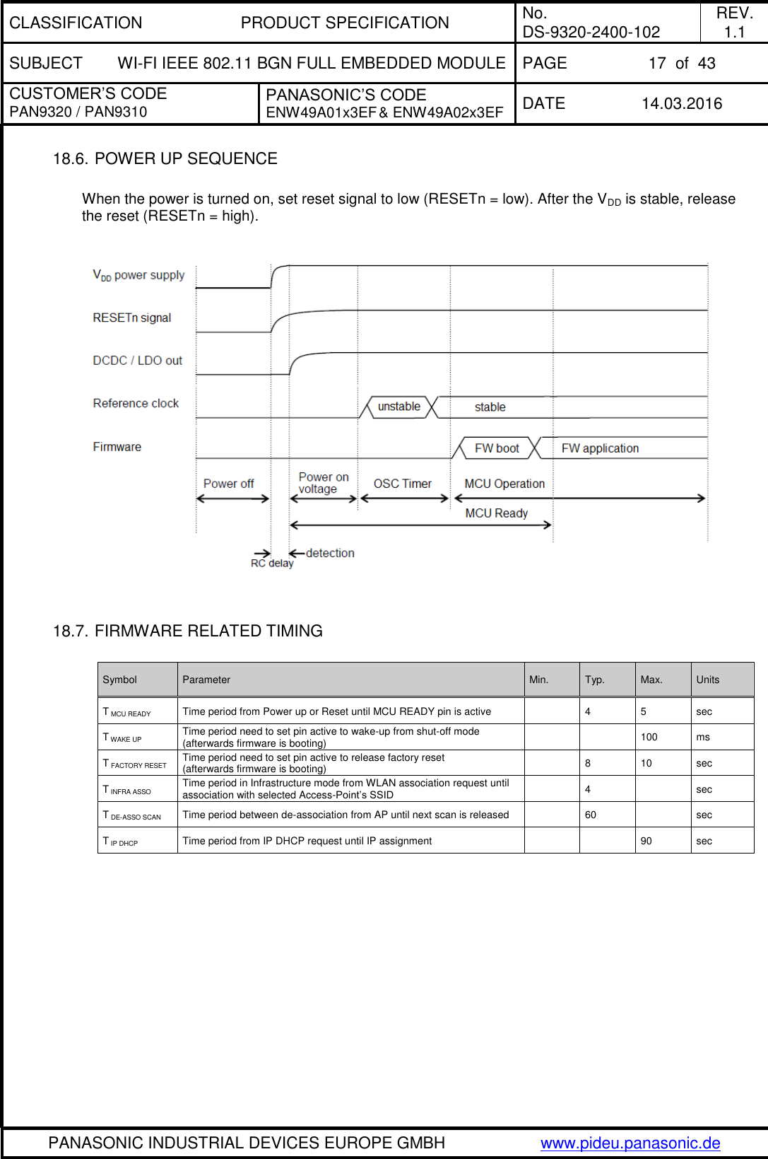
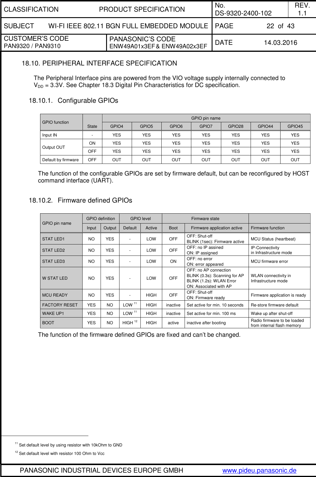
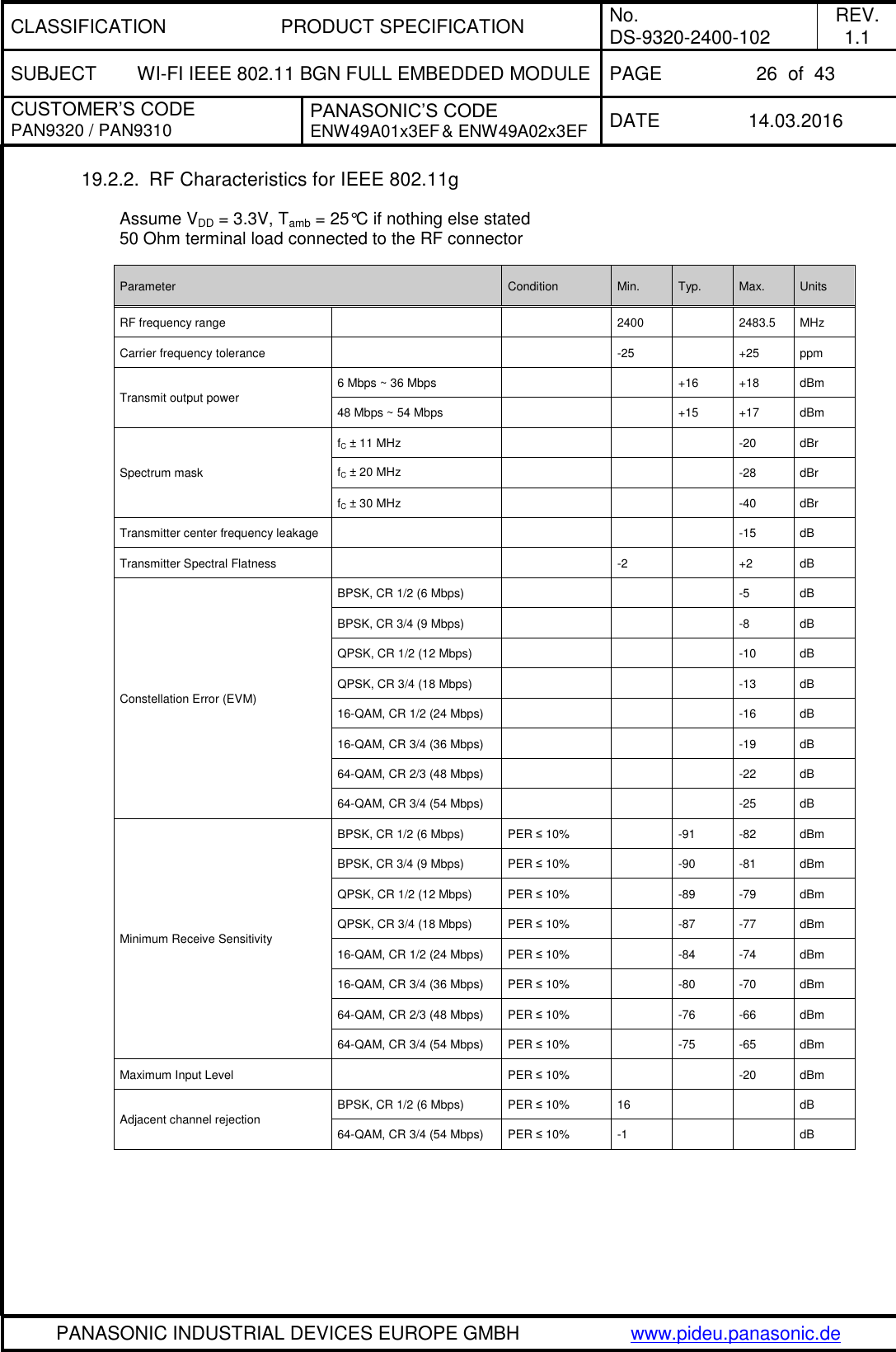
![CLASSIFICATION PRODUCT SPECIFICATION No. DS-9320-2400-102 REV. 1.1 SUBJECT WI-FI IEEE 802.11 BGN FULL EMBEDDED MODULE PAGE 6 of 43 CUSTOMER’S CODE PAN9320 / PAN9310 PANASONIC’S CODE ENW49A01x3EF & ENW49A02x3EF DATE 14.03.2016 PANASONIC INDUSTRIAL DEVICES EUROPE GMBH www.pideu.panasonic.de 5. KEY FEATURES Surface Mount Type (SMT) measured 29.0 x 13.5 x 2.66 [mm]³ Wireless Local Area Network (WLAN) module with integrated MCU and Radio Operating in the 2.4GHz ISM band Supports the following IEEE 802.11 standards: IEEE 802.11b/g payload data rates IEEE 802.11n high throughput data rates IEEE 802.11i security: WEP and WPA/WPA2 (TKIP, AES-CCMP) IEEE 802.11e Quality of Service (QoS) TX power up to +18dBm (for IEEE 802.11b) Outstanding RX sensitivity -98dBm (IEEE 802.11b DSSS 1Mbps) -75dBm (IEEE 802.11g OFDM 54Mbps) -73dBm (IEEE 802.11n MCS7 HT20 65Mbps) -70dBm (IEEE 802.11n MCS7 HT40 135Mbps) Marvell® 88W8782 WLAN System-on-Chip (SoC) and 88MC200 (MCU) inside High performance low power CPU core Coexistence interface for external co-located 2.4GHz radios (e.g. Bluetooth) Internal crystal oscillators for Radio (40MHz) and MCU (32MHz) Integrated memory flash for customer web contents and configuration file (1MByte) Memory extension with an external QSPI flash (2MByte) is optional Two UART interfaces (command and binary data) Integrated shielding to resist EMI Manufactured in conformance with RoHS Available with either integrated antenna (PAN9320) or dedicated RF pad for external antennas (PAN9310) 6. APPLICATIONS FOR THE PAN9320 All Embedded Wireless Applications White Good Printer Home Automation Smart Meters Internet of Things Media Player Fitness Equipment Sensors Lighting Control POS Terminal M2M Communication Patient Monitors](https://usermanual.wiki/Panasonic-Devices-Europe/9320/User-Guide-2934779-Page-6.png)
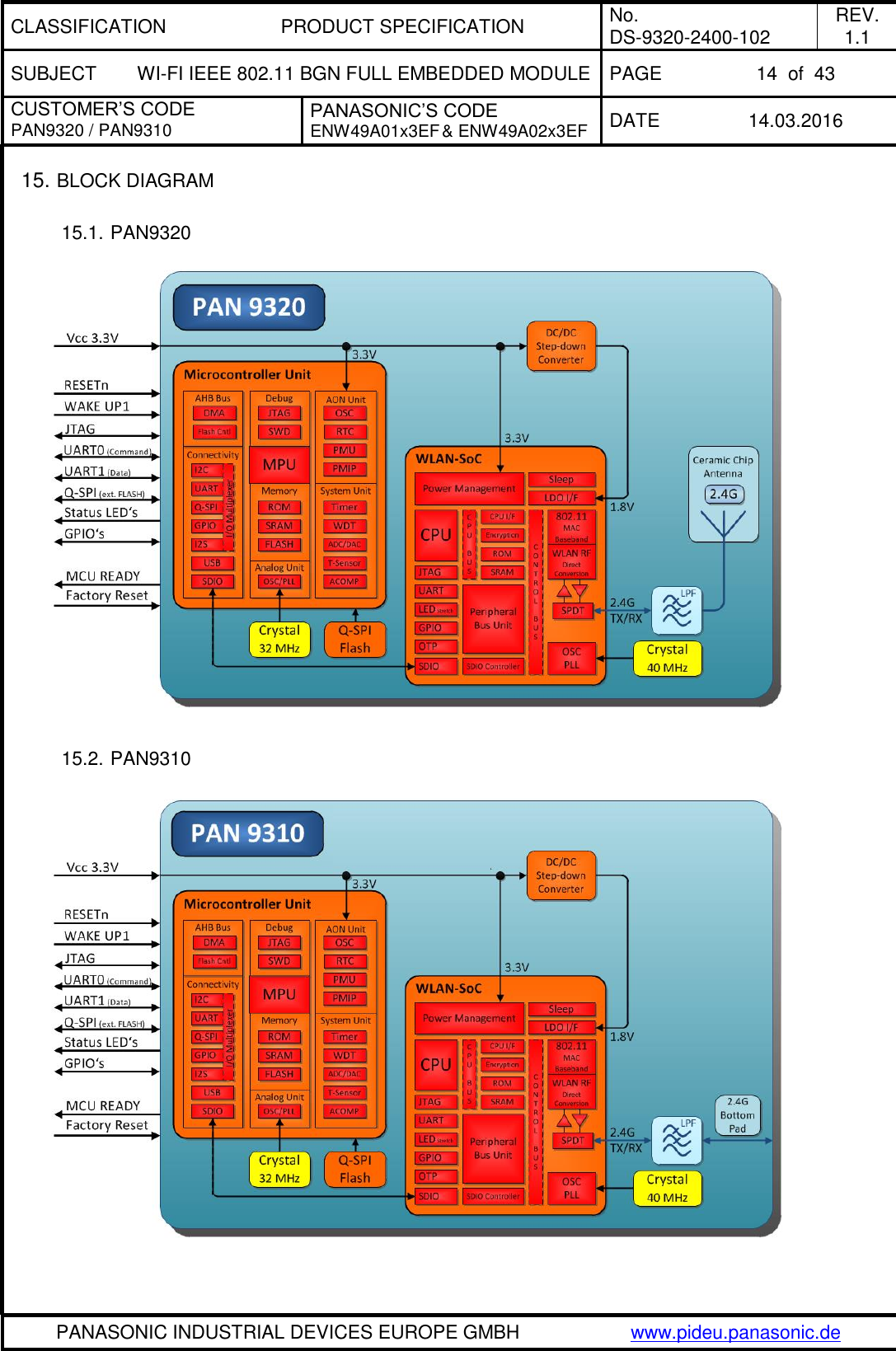
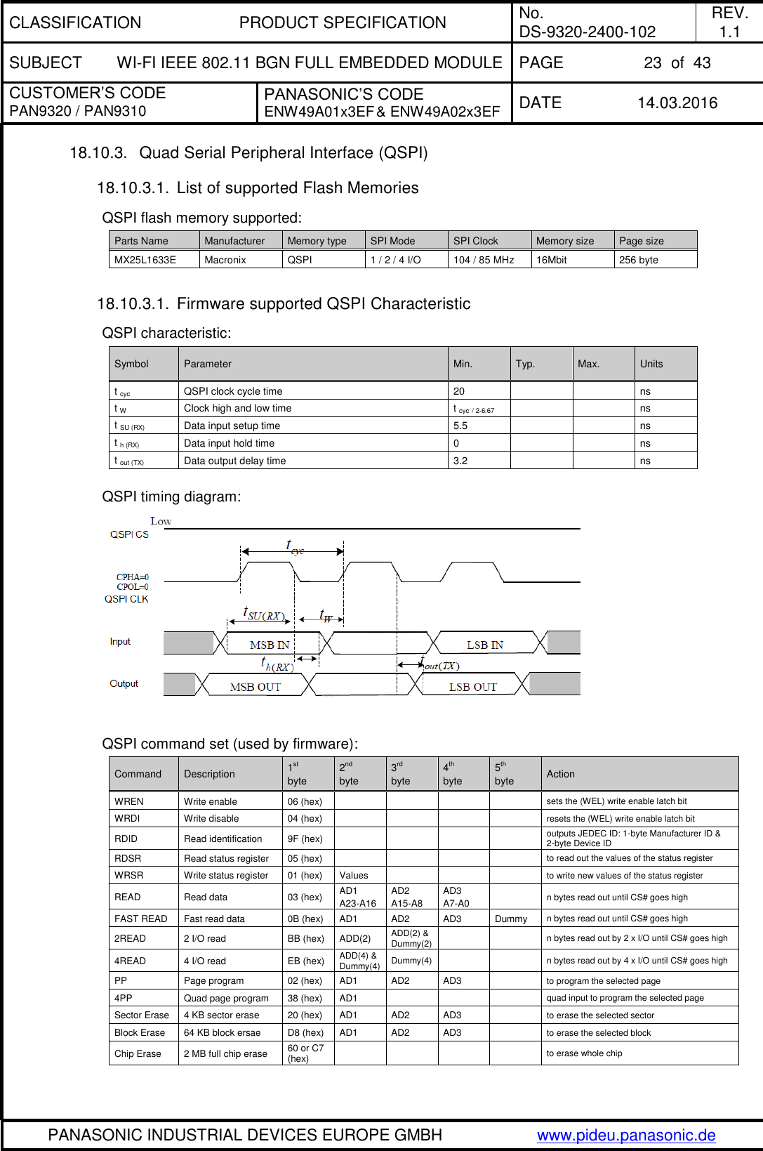
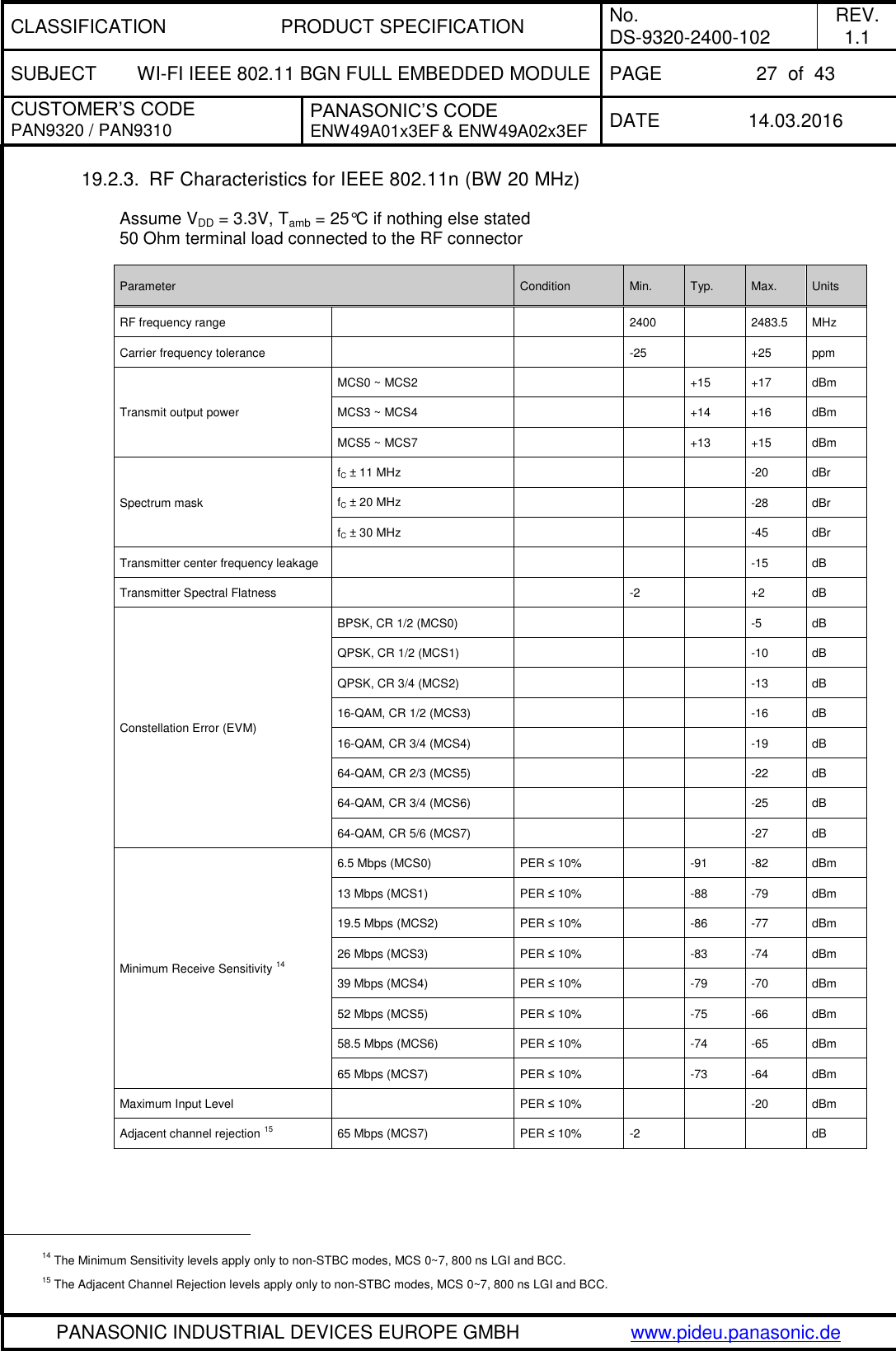
![CLASSIFICATION PRODUCT SPECIFICATION No. DS-9320-2400-102 REV. 1.1 SUBJECT WI-FI IEEE 802.11 BGN FULL EMBEDDED MODULE PAGE 7 of 43 CUSTOMER’S CODE PAN9320 / PAN9310 PANASONIC’S CODE ENW49A01x3EF & ENW49A02x3EF DATE 14.03.2016 PANASONIC INDUSTRIAL DEVICES EUROPE GMBH www.pideu.panasonic.de 7. WIRELESS LOCAL AREA NETWORK OVERVIEW A Wireless Local Area Network (WLAN) is a medium range, wireless network based on the IEEE 802.11 standard, and uses the ubiquities ISM (Industrial, Scientific and Medical) frequency range of 2,4GHz. The 802.11 standard pertains to the first two layers of the OSI model, and covers Physical Layer (PHY), the Data Link Layer (DLL) with its two sub-layers: Logical Link Control (LLC), and Media Access Control (MAC). WLAN networks utilize two operating modes to connect stations (STAs) equipped with a wireless network adapter. The first is known as the Infrastructure Mode where the wireless STAs are connected via one or more access points (APs). An AP is a device that allows STAs to connect with each other or to a wired network. The second is the Ad-hoc mode, where wireless STAs are connected without any access point. WLAN devices typically have a high transmit power, of 15 to 20 dBm, allowing them to reach a range of up to 100 meters. Furthermore, WLAN devices are commonly used to transmit high throughput data such as Audio or Video streaming using Orthogonal Frequency Division Multiplexing (OFDM) modulation. The Carrier Sense Multiple Access with Collosion Avoidance (CSMA/CA) mechanism enables the parallel access of more than one device to the wireless medium of a IEEE 802.11 network. The following security mechanisms are deployed: 1. Adavanced Encryption Standard (AES) with Counter Mode CBC-MAC Protocol (CCMP), 2. Cipher-Based Message Authentication Code (CMAC) and 3. Wired Equivalent Privacy (WEP) with Temporal Key Integrity Protocol (TKIP). Video, voice and multimedia applications are supported by the IEEE 802.11e Quality of Service amendment. 8. DESCRIPTION OF THE PAN9320 The PAN9320 module is a WLAN embedded module with a 2.4GHz ISM band wireless radio and an MCU for introduce WLAN connectivity into various electronic devices. A block diagram can be found in chapter 15. The module is a cost-effective, low-power, fully embedded WLAN solution for the Internet of Things (IoT). It offers the customer an easy integration with a low bill-of-material. The module offers Internet functionality through HTML and JavaScript Web technologies. The PAN9320 combines advanced 802.11 wireless radio, baseband processor, medium access controller (MAC), encryption units, controlled by a powerful CPU. Furthermore, MCU offers an in-system programmable flash memory as well as many other powerful supporting features and peripherals. The module is suitable for wireless network systems based on IEEE 802.11 b/g/n 2.4GHz where small form factor, highly integration, high throughput data rates and low RF expertise are required. It supports simultaneous Access-Point and Infrastructure Mode. The PAN9320 integrated MCU’s firmware consists of software modules with TCP/IP Network Stack, TLS1.2 Security Suite, UDP Name Services and various applications like Web Server, SMTP(s) Client, HTTP(s) Client and Cloud Communication Client on top of the 802.11 WLAN stack with WPA/WPA2 Supplicant. The integrated flash is used for customer web contents and configuration files with a usable memory size of 1 MByte. The memory size can be extended by using an external QSPI flash memory of 2 MByte. The radio driver, MCU firmware, configuration files and web content can be updated Over-The-Air (OTA). Refer to Quick Start Guide[1], Communication Specification[1], Design Guide[4] and chapter 28. Ordering Information. Please contact your local sales office for further details on additional options and services: www.panasonic.com/rfmodules for the US, http://industrial.panasonic.com/eu/i/29606/wireless_modules/wireless_modules.html for EU or write an e-mail to wireless@eu.panasonic.com. 9. DIFFERENCE PAN9320 TO PAN9310 The PAN9320 has an integrated antenna and the PAN9310 has a dedicated RF pad for external antenna connection.](https://usermanual.wiki/Panasonic-Devices-Europe/9320/User-Guide-2934779-Page-7.png)
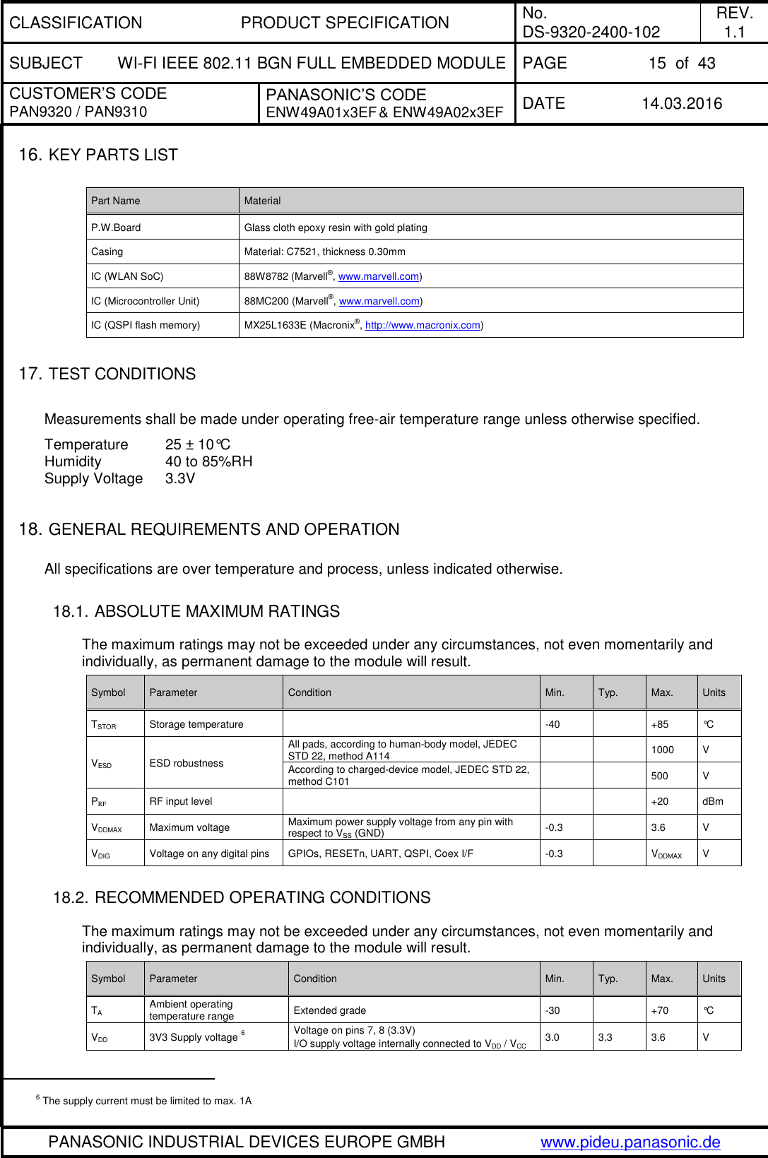
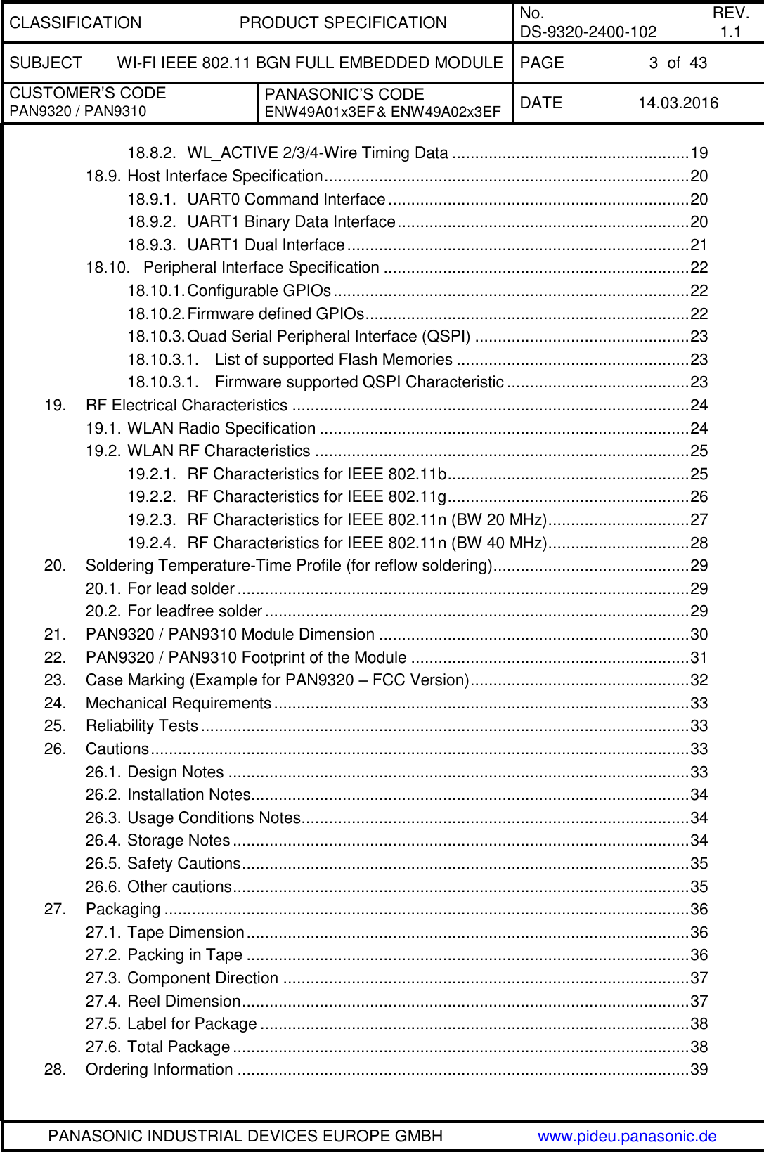
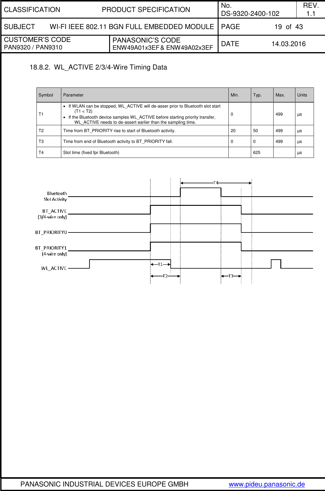
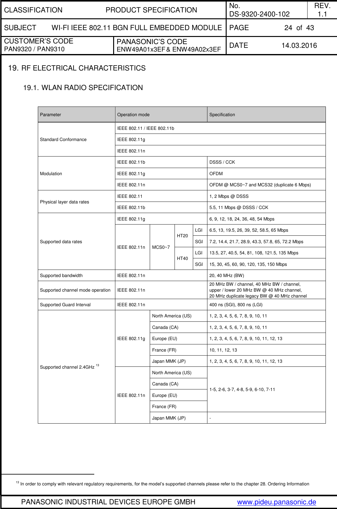
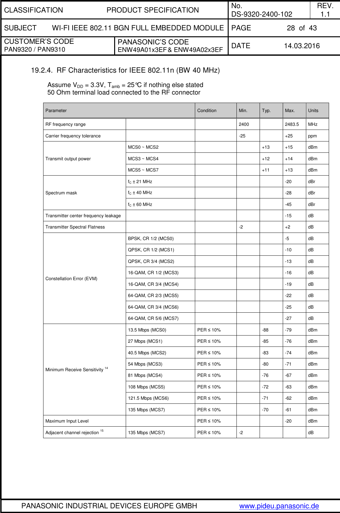
![CLASSIFICATION PRODUCT SPECIFICATION No. DS-9320-2400-102 REV. 1.1 SUBJECT WI-FI IEEE 802.11 BGN FULL EMBEDDED MODULE PAGE 18 of 43 CUSTOMER’S CODE PAN9320 / PAN9310 PANASONIC’S CODE ENW49A01x3EF & ENW49A02x3EF DATE 14.03.2016 PANASONIC INDUSTRIAL DEVICES EUROPE GMBH www.pideu.panasonic.de 18.8. COEXISTENCE INTERFACE SPECIFICATION The Coexistence Interface pins are powered from the VIO voltage supply internally connected to VDD = 3.3V. See Chapter 18.3 Digital Pin Characteristics for DC specification. 18.8.1. Marvell® 3/4-Wire Timing Data Symbol Parameter Min. Typ. Max. Units T1 Priority[0] info is valid in BT_STATE on and after T1 from BT_REQ rise. 0 1 100 µs T2 TxRx Info is valid in BT_STATE on and after T2. The BT_STATE must hold until there is any change of direction in the next slots. 2 19 100 µs T3 Time from TxRx Info valid to BCA grant decision (T3 = T7 – T4 – T2 – T8 – T1). 2 40 594 µs T4 BT_GRANTn needs to be valid T4 time before the upcoming slot. BT_GRANTn indicates Tx grant, and may also indicate Rx grant. Once a slot is granted, the subsequent slots are also granted unless there is a change in direction from Rx to Tx. Rx to Tx change always re-arbitrates. 2 80 594 µs T5 TxRx Info for the next slot is valid on and after T5 to the start of the next slot. If direction remains the same for the next slot, then BT_STATE must not change during the current slot. If the direction changes for the next slot, the BT_STATE must change only after the last bit of Bluetooth data is transferred; otherwise the transfer may be disrupted. 5 40 600 µs T6 The BT_REQ signal de-asserts T6 time after last bit of Bluetooth data is transferred. 0 15 25 µs T7 Time from BT_REQ rise to first Bluetooth slot boundary. Bluetooth slot boundary is marked by first bit of Bluetooth data. 8 150 600 µs T8 Optional Priority[1] information is valid in BT_STAT on and after T8. This time parameter only exists if BCA is configured for 2-bit priority on same BT_STATE pin. Otherwise, the start of T2 would come after T1. 2 10 100 µs Ttx Slot time (fixed fpr Bluetooth) 625 µs Trx Slot time (fixed fpr Bluetooth) 625 µs](https://usermanual.wiki/Panasonic-Devices-Europe/9320/User-Guide-2934779-Page-18.png)
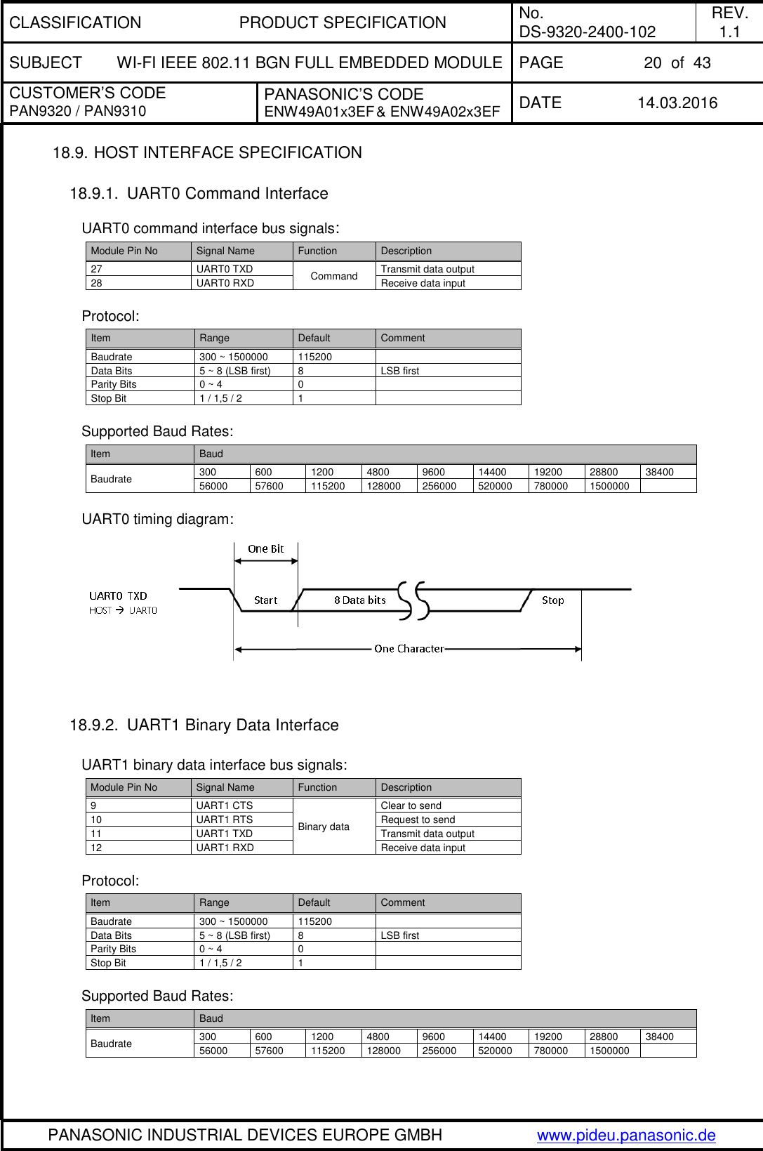
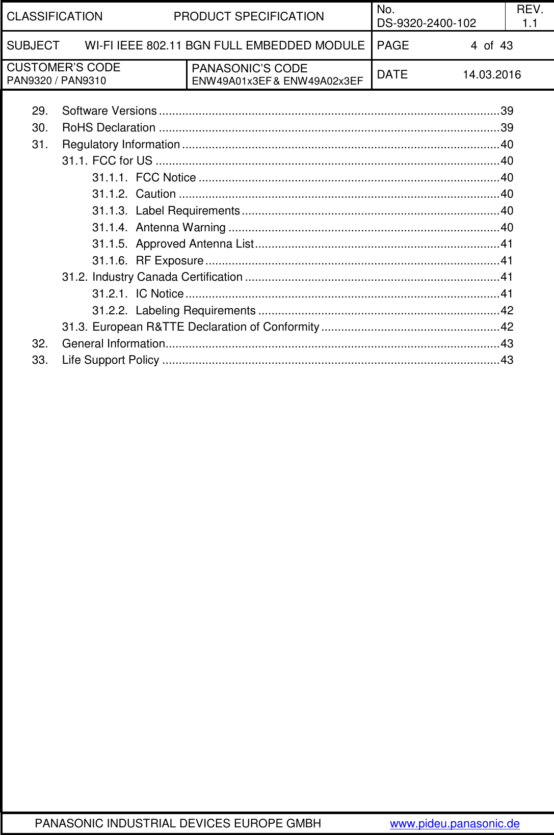
![CLASSIFICATION PRODUCT SPECIFICATION No. DS-9320-2400-102 REV. 1.1 SUBJECT WI-FI IEEE 802.11 BGN FULL EMBEDDED MODULE PAGE 29 of 43 CUSTOMER’S CODE PAN9320 / PAN9310 PANASONIC’S CODE ENW49A01x3EF & ENW49A02x3EF DATE 14.03.2016 PANASONIC INDUSTRIAL DEVICES EUROPE GMBH www.pideu.panasonic.de 20. SOLDERING TEMPERATURE-TIME PROFILE (FOR REFLOW SOLDERING) 20.1. FOR LEAD SOLDER Recommended temp. profile for reflow soldering Temp.[°C] Time [s] 235°C max. 220 5°C 200°C 150 10°C 90 30s 10 1s 30 +20/-10s 20.2. FOR LEADFREE SOLDER Our used temp. profile for reflow soldering Temp.[°C] Time [s] 230°C -250°C max. 220°C 150°C – 190°C 90 30s 30 +20/-10s Reflow permissible cycle: 2 Opposite side reflow is prohibited due to module weight.](https://usermanual.wiki/Panasonic-Devices-Europe/9320/User-Guide-2934779-Page-29.png)
![CLASSIFICATION PRODUCT SPECIFICATION No. DS-9320-2400-102 REV. 1.1 SUBJECT WI-FI IEEE 802.11 BGN FULL EMBEDDED MODULE PAGE 34 of 43 CUSTOMER’S CODE PAN9320 / PAN9310 PANASONIC’S CODE ENW49A01x3EF & ENW49A02x3EF DATE 14.03.2016 PANASONIC INDUSTRIAL DEVICES EUROPE GMBH www.pideu.panasonic.de 26.2. INSTALLATION NOTES (1) Reflow soldering is possible twice based on the conditions in chapter 15. Set up the temperature at the soldering portion of this product according to this reflow profile. (2) Carefully position the products so that their heat will not burn into printed circuit boards or affect the other components that are susceptible to heat. (3) Carefully locate these products so that their temperatures will not increase due to the effects of heat generated by neighboring components. (4) If a vinyl-covered wire comes into contact with the products, then the cover will melt and generate toxic gas, damaging the insulation. Never allow contact between the cover and these products to occur. (5) This product should not be mechanically stressed or vibrated when reflowed. (6) To repair the board by hand soldering, follow the conditions set forth in this chapter. (7) Do not wash this product. (8) Refer to the recommended pattern when designing a board. (9) Pressing on parts of the metal cover or fastening objects to the metal will cause damage to the unit. (10) For more details on LGA (Land Grid Array) soldering processes refer to the application note [7]. 26.3. USAGE CONDITIONS NOTES (1) Take measures to protect the unit against static electricity. If pulses or other transient loads (a large load applied in a short time) are applied to the products, check and evaluate their operation befor assembly on the final products. (2) Do not use dropped products. (3) Do not touch, damage or soil the pins. (4) Follow the recommended condition ratings about the power supply applied to this product. (5) Electrode peeling strength: Do not add pressure of more than 4.9N when soldered on PCB. (6) Pressing on parts of the metal cover or fastening objects to the metal cover will cause damage. (7) These products are intended for general purpose and standard use in general electronic equipment, such as home appliances, office equipment, information and communication equipment. 26.4. STORAGE NOTES (1) The module should not be stressed mechanically during storage. (2) Do not store these products in the following conditions or the performance characteristics of the product, such as RF performance will be adversely affected: Storage in salty air or in an environment with a high concentration of corrosive gas, such as Cl2, H2S, NH3, SO2, or NOX Storage in direct sunlight Storage in an environment where the temperature may be outside the range of 5°C to 35°C range, or where the humidity may be outside the 45 to 85% range. Storage of the products for more than one year after the date of delivery Storage period: Please check the adhesive strength of the embossed tape and soldering after 6 months of storage. (3) Keep this product away from water, poisonous gas and corrosive gas. (4) This product should not be stressed or shocked when transported. (5) Follow the specification when stacking packed crates (max. 10).](https://usermanual.wiki/Panasonic-Devices-Europe/9320/User-Guide-2934779-Page-34.png)
![CLASSIFICATION PRODUCT SPECIFICATION No. DS-9320-2400-102 REV. 1.1 SUBJECT WI-FI IEEE 802.11 BGN FULL EMBEDDED MODULE PAGE 38 of 43 CUSTOMER’S CODE PAN9320 / PAN9310 PANASONIC’S CODE ENW49A01x3EF & ENW49A02x3EF DATE 14.03.2016 PANASONIC INDUSTRIAL DEVICES EUROPE GMBH www.pideu.panasonic.de 27.5. LABEL FOR PACKAGE The picture shows an example from similar product. (1T) Lot code [YYWWDLL-AAA] Example from above: YY year printed 08 WW normal calendar week printed 01 D day printed 5 (Friday) L line identifier, if more as one printed 1 L lot identifier per day printed 1 AAA number of the reel (example 001, 002,…, 999) printed 001 (1P) Customer Order Code, if any, otherwise company name will be printed (2P) Panasonic Order Code: ENW49A01A3EF (see chapter 28 Ordering Information) (3P) Model type (see chapter 28. Ordering Information) (9D) Date code as [YYWW] (Q) Quantity [XXXX], variable max. 500 (HW/SW) Hardware/Software Release 27.6. TOTAL PACKAGE barcodelabelmoisture-sensitive print(already exist on barrier bag) barcodelabeldesiccant 1) 2)moisture indicatorbarrier bagsealedinner carton boxsize 340 x 340 x 41 mm³1) quantity of desiccant according to calculation2) optional: desiccant placed into the corner of the barrier bag (3P): PAN9320 RoHS -AAA ENW49A01A3EF Company 500 xy/ab Country of Origin: Slovakia](https://usermanual.wiki/Panasonic-Devices-Europe/9320/User-Guide-2934779-Page-38.png)
![CLASSIFICATION PRODUCT SPECIFICATION No. DS-9320-2400-102 REV. 1.1 SUBJECT WI-FI IEEE 802.11 BGN FULL EMBEDDED MODULE PAGE 39 of 43 CUSTOMER’S CODE PAN9320 / PAN9310 PANASONIC’S CODE ENW49A01x3EF & ENW49A02x3EF DATE 14.03.2016 PANASONIC INDUSTRIAL DEVICES EUROPE GMBH www.pideu.panasonic.de 28. ORDERING INFORMATION Model Name Brand Name Regulatory Supported Channel Description MOQ (4) ENW49A01A3EF PAN9320 FCC / IC (1) for US and for Canada Channel 1 ~ 11 2412 ~ 2462 MHz WLAN IEEE 802.11 b/g/n 2.4GHz Full Embedded Module with ceramic chip-antenna 500 ENW49A01C3EF PAN9310 (3) WLAN IEEE 802.11 b/g/n 2.4GHz Full Embedded Module with RF bottom pad 500 ENW49A02A3EF PAN9320 ETSI (2) for EU and other Channel 1 ~ 13 2412 ~ 2472 MHz WLAN IEEE 802.11 b/g/n 2.4GHz Full Embedded Module with ceramic chip-antenna 500 ENW49A02C3EF PAN9310 (3) WLAN IEEE 802.11 b/g/n 2.4GHz Full Embedded Module with RF bottom pad 500 The PAN9320 / PAN9310 will be delivered with a pre-installed firmware, see PAN9320 Communication Specification [3] and PAN9320 Design Guide [1]. Notes: (1) The model with Regulatory Domain FCC / IC (M/N: ENW49A01A3EF) are only intended to be used in the countries of US and Canada because only the channels 1 ~ 11 (2412 ~ 2462 MHz) are supported in the 2.4GHz ISM band. It is not possible to change the pre-stored Region Code in order to change the Regulatory Domain. Thus the module labeling contains the FCC Grant ID. (2) The model with Regulatory Domain ETSI (M/N: ENW49A02A3EF) are mainly intended to be used in European countries because the channels 1 ~ 13 (2412 ~ 2472 MHz) are supported. The Region Code is pre-configured (using Default Config Content in Flash memory) to Regulatory Domain ETSI and thus the module labeling doesn’t contain the FCC ID. At the end the customer is able to change applied Region Code by his own Customer Config Content to be stored during customer OEMs product production in the flash memory. It means the FCC Regulatory Domain can be configured as well, but the customer has to certify the end product by itself. (3) The models with brand name PAN9310 don’t have the Chip antenna on module. The Grant ID’s marked on module labelling are referenced and are only valid in case of customer is applying the same antenna (listed in 31.1.5) including the reference design described in the Design Guide [1]. In this case the customer can refer to the pre-qualified module’s modular approval which needs finally to be approved by the certification body of regulatory authority. (4) Abbreviation for Minimum Order Quantity (MOQ). The standard MOQ for mass production is 500 pieces, fewer only on customer demand. Samples for evaluation can be delivered at any quantity via the distribution channels. 29. SOFTWARE VERSIONS The version numbers of the embedded MCU firmware and WLAN SoC firmware can be read out by UART commands which are specified in the PAN9320 Communication Specification [3] and listed below: No. Item UART Command Response example 1 MCU firmware version get system firmware get system firmware 0 1.9.0.1 2 WLAN SoC firmware version get system wifi_ver get system wifi_ver 0 "w8782-B0, RF878X, FP69, 14.69.12.p40" 30. ROHS DECLARATION Declaration of environmental compatibility for supplied products: Hereby we declare to our best present knowledge based on declaration of our suppliers that this product does not contain the following substances which are banned by Directive 2002/95/EC (RoHS) or contains a maximum concentration of 0.1% by weight in homogeneous materials for Lead and lead compounds Mercury and mercury compounds Chromium (VI) PBB (polybrominated biphenyl) category PBDE (polybrominated biphenyl ether) category And a maximum concentration of 0.01% by weight in homogeneous materials for Cadmium and cadmium compounds](https://usermanual.wiki/Panasonic-Devices-Europe/9320/User-Guide-2934779-Page-39.png)