Panasonic Devices Europe 9320 Wireless LAN Embedded Module User Manual TABLE OF CONTENTS
Panasonic Industrial Devices Europe GmbH Wireless LAN Embedded Module TABLE OF CONTENTS
15_ENW49A013EF_(PAN9320+PAN9310)_UserMan

CLASSIFICATION
PRODUCT SPECIFICATION
No.
DS-9320-2400-102
REV.
1.1
SUBJECT
WI-FI IEEE 802.11 BGN FULL EMBEDDED MODULE
PAGE
1 of 43
CUSTOMER’S CODE
PAN9320 / PAN9310
PANASONIC’S CODE
ENW49A01x3EF & ENW49A02x3EF
DATE
14.03.2016
Power Electronics R&D Center
Wireless Connectivity
Panasonic Industrial Devices Europe GmbH
APPROVED
CHECKED
DESIGNED
Product Specification
Applicant / Manufacturer
Hardware
Panasonic Industrial Devices Europe GmbH
Zeppelinstrasse 19
21337 Lüneburg
Germany
Applicant / Manufacturer
Software
Please refer to chapter 28. Ordering Information
Software Version
Please refer to chapter 29. Software Versions
By purchase of any of products described in this document the customer accepts the document's
validity and declares their agreement and understanding of its contents and recommendations.
Panasonic reserves the right to make changes as required without notification.

CLASSIFICATION
PRODUCT SPECIFICATION
No.
DS-9320-2400-102
REV.
1.1
SUBJECT
WI-FI IEEE 802.11 BGN FULL EMBEDDED MODULE
PAGE
2 of 43
CUSTOMER’S CODE
PAN9320 / PAN9310
PANASONIC’S CODE
ENW49A01x3EF & ENW49A02x3EF
DATE
14.03.2016
PANASONIC INDUSTRIAL DEVICES EUROPE GMBH
www.pideu.panasonic.de
TABLE OF CONTENTS
1. Scope of this Document ................................................................................................ 5
2. History for this Document .............................................................................................. 5
3. Data Sheet Status ......................................................................................................... 5
4. Related Documents ....................................................................................................... 5
5. Key Features ................................................................................................................. 6
6. Applications for the PAN9320 ........................................................................................ 6
7. Wireless Local Area Network Overview ......................................................................... 7
8. Description of the PAN9320 .......................................................................................... 7
9. Difference PAN9320 to PAN9310 .................................................................................. 7
10. Detailed Description ...................................................................................................... 8
10.1. PAN9320 / PAN9310 Terminal Layout ................................................................. 8
10.2. Common Terminal Pin-Configuration ................................................................... 8
11. General Features ........................................................................................................ 10
12. HOST Interfaces ......................................................................................................... 10
12.1. UART0 Interface ................................................................................................ 10
12.2. UART1 Interface ................................................................................................ 10
13. Peripheral Bus Interface .............................................................................................. 11
14. WLAN Features ........................................................................................................... 12
14.1. IEEE 802.11 / Standards .................................................................................... 12
14.2. WLAN MAC ........................................................................................................ 12
14.3. WLAN Baseband ................................................................................................ 12
14.4. WLAN Radio ...................................................................................................... 13
14.5. WLAN Encryption ............................................................................................... 13
15. Block Diagram ............................................................................................................. 14
15.1. PAN9320............................................................................................................ 14
15.2. PAN9310............................................................................................................ 14
16. Key Parts List .............................................................................................................. 15
17. Test Conditions ........................................................................................................... 15
18. General Requirements and Operation ......................................................................... 15
18.1. Absolute Maximum Ratings ................................................................................ 15
18.2. Recommended Operating Conditions ................................................................. 15
18.3. Digital Pin Characteristics .................................................................................. 16
18.4. Electrical characeristics ...................................................................................... 16
18.4.1. Current Consumption ............................................................................ 16
18.5. Internal Operating Frequencies .......................................................................... 16
18.6. Power Up Sequence .......................................................................................... 17
18.7. Firmware related Timing ..................................................................................... 17
18.8. Coexistence Interface Specification.................................................................... 18
18.8.1. Marvell® 3/4-Wire Timing Data .............................................................. 18

CLASSIFICATION
PRODUCT SPECIFICATION
No.
DS-9320-2400-102
REV.
1.1
SUBJECT
WI-FI IEEE 802.11 BGN FULL EMBEDDED MODULE
PAGE
3 of 43
CUSTOMER’S CODE
PAN9320 / PAN9310
PANASONIC’S CODE
ENW49A01x3EF & ENW49A02x3EF
DATE
14.03.2016
PANASONIC INDUSTRIAL DEVICES EUROPE GMBH
www.pideu.panasonic.de
18.8.2. WL_ACTIVE 2/3/4-Wire Timing Data .................................................... 19
18.9. Host Interface Specification ................................................................................ 20
18.9.1. UART0 Command Interface .................................................................. 20
18.9.2. UART1 Binary Data Interface ................................................................ 20
18.9.3. UART1 Dual Interface ........................................................................... 21
18.10. Peripheral Interface Specification ................................................................... 22
18.10.1. Configurable GPIOs .............................................................................. 22
18.10.2. Firmware defined GPIOs ....................................................................... 22
18.10.3. Quad Serial Peripheral Interface (QSPI) ............................................... 23
18.10.3.1. List of supported Flash Memories ................................................... 23
18.10.3.1. Firmware supported QSPI Characteristic ........................................ 23
19. RF Electrical Characteristics ....................................................................................... 24
19.1. WLAN Radio Specification ................................................................................. 24
19.2. WLAN RF Characteristics .................................................................................. 25
19.2.1. RF Characteristics for IEEE 802.11b ..................................................... 25
19.2.2. RF Characteristics for IEEE 802.11g ..................................................... 26
19.2.3. RF Characteristics for IEEE 802.11n (BW 20 MHz) ............................... 27
19.2.4. RF Characteristics for IEEE 802.11n (BW 40 MHz) ............................... 28
20. Soldering Temperature-Time Profile (for reflow soldering) ........................................... 29
20.1. For lead solder ................................................................................................... 29
20.2. For leadfree solder ............................................................................................. 29
21. PAN9320 / PAN9310 Module Dimension .................................................................... 30
22. PAN9320 / PAN9310 Footprint of the Module ............................................................. 31
23. Case Marking (Example for PAN9320 – FCC Version) ................................................ 32
24. Mechanical Requirements ........................................................................................... 33
25. Reliability Tests ........................................................................................................... 33
26. Cautions ...................................................................................................................... 33
26.1. Design Notes ..................................................................................................... 33
26.2. Installation Notes ................................................................................................ 34
26.3. Usage Conditions Notes ..................................................................................... 34
26.4. Storage Notes .................................................................................................... 34
26.5. Safety Cautions .................................................................................................. 35
26.6. Other cautions .................................................................................................... 35
27. Packaging ................................................................................................................... 36
27.1. Tape Dimension ................................................................................................. 36
27.2. Packing in Tape ................................................................................................. 36
27.3. Component Direction ......................................................................................... 37
27.4. Reel Dimension .................................................................................................. 37
27.5. Label for Package .............................................................................................. 38
27.6. Total Package .................................................................................................... 38
28. Ordering Information ................................................................................................... 39

CLASSIFICATION
PRODUCT SPECIFICATION
No.
DS-9320-2400-102
REV.
1.1
SUBJECT
WI-FI IEEE 802.11 BGN FULL EMBEDDED MODULE
PAGE
4 of 43
CUSTOMER’S CODE
PAN9320 / PAN9310
PANASONIC’S CODE
ENW49A01x3EF & ENW49A02x3EF
DATE
14.03.2016
PANASONIC INDUSTRIAL DEVICES EUROPE GMBH
www.pideu.panasonic.de
29. Software Versions ....................................................................................................... 39
30. RoHS Declaration ....................................................................................................... 39
31. Regulatory Information ................................................................................................ 40
31.1. FCC for US ........................................................................................................ 40
31.1.1. FCC Notice ........................................................................................... 40
31.1.2. Caution ................................................................................................. 40
31.1.3. Label Requirements .............................................................................. 40
31.1.4. Antenna Warning .................................................................................. 40
31.1.5. Approved Antenna List .......................................................................... 41
31.1.6. RF Exposure ......................................................................................... 41
31.2. Industry Canada Certification ............................................................................. 41
31.2.1. IC Notice ............................................................................................... 41
31.2.2. Labeling Requirements ......................................................................... 42
31.3. European R&TTE Declaration of Conformity ...................................................... 42
32. General Information ..................................................................................................... 43
33. Life Support Policy ...................................................................................................... 43

CLASSIFICATION
PRODUCT SPECIFICATION
No.
DS-9320-2400-102
REV.
1.1
SUBJECT
WI-FI IEEE 802.11 BGN FULL EMBEDDED MODULE
PAGE
5 of 43
CUSTOMER’S CODE
PAN9320 / PAN9310
PANASONIC’S CODE
ENW49A01x3EF & ENW49A02x3EF
DATE
14.03.2016
PANASONIC INDUSTRIAL DEVICES EUROPE GMBH
www.pideu.panasonic.de
1. SCOPE OF THIS DOCUMENT
This product specification applies to Panasonic’s Wi-Fi IEEE 802.11 b/g/n full embedded module with brand
names PAN9320 and PAN9310.
2. HISTORY FOR THIS DOCUMENT
Revision
Date
Modification / Remarks
0.1
22.04.2015
1st preliminary version
1.0
26.11.2015
Adapt Panasonic’s Code by adding model ENW49A02x3EF
Adapt information in chapter:
4 Related Documents, 5 Key Features, 7 WLAN Overview, 8 Description of the , 10 Detailed Description,
11 General Features, 15 Block Diagram, 18.9 Host Interface Specification, 19 RF Electrical Characteristics,
21 PAN9320 / PAN9310 Module Dimension, 22 PAN9320 / PAN9310 Footprint of the Module,
23 Case Marking (Example for PAN9320 – FCC Version) , and 28 Ordering Information
Add chapter: 13 Peripheral Bus Interface, 18.6 Power Up Sequence, 18.7 Firmware related Timing,
29 Software Versions, and 31 Regulatory Information
1.1
14.03.2016
Adapt information in chapter 31.1.6 RF Exposure
3. DATA SHEET STATUS
This data sheet contains the PRELIMINARY specification. Supplementary data will be published at a later
date.
Panasonic reserves the right to make changes at any time without notice.
Consult the most recently issued data sheet before initiating or completing a design.
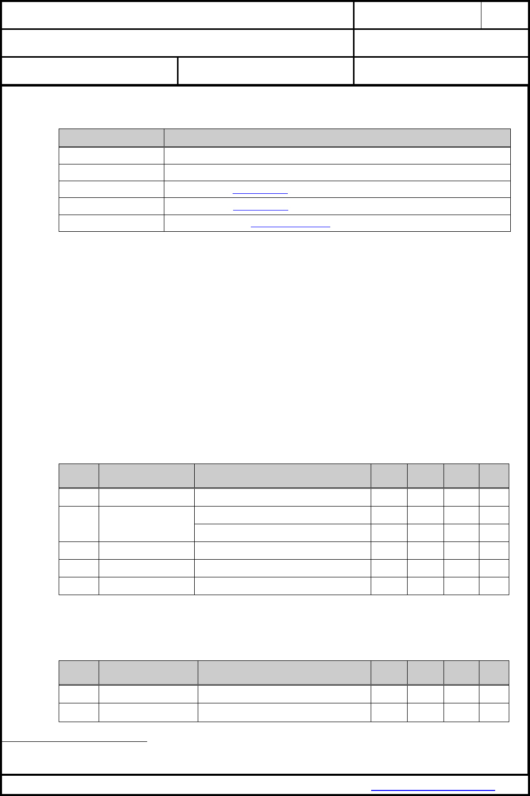
4. RELATED DOCUMENTS
Search these homepages for documentation updates.
[1] PAN9320 Flyer
PAN9320 Download Page (Flyer)
[2] PAN9320 Design Guide
PAN9320 Download Page (Design Guide)
[3] PAN9320 Quick Start Guide
PAN9320 Download Page (Quick Start Guide)
[4] PAN9320 Communication Specification
PAN9320 Download Page (Communication Specification)
[5] PAN9320 Application Note
PAN9320 Download Page (Application Note)
[6] Semiconductor Datasheet
88MC200 from Marvell®
88W8782 from Marvell®
[7] Application Note Land Grid Array
Land Grid Array
[8] REACH and RoHS Certificate
WM-REACH_and_RoHS_directive

CLASSIFICATION
PRODUCT SPECIFICATION
No.
DS-9320-2400-102
REV.
1.1
SUBJECT
WI-FI IEEE 802.11 BGN FULL EMBEDDED MODULE
PAGE
6 of 43
CUSTOMER’S CODE
PAN9320 / PAN9310
PANASONIC’S CODE
ENW49A01x3EF & ENW49A02x3EF
DATE
14.03.2016
PANASONIC INDUSTRIAL DEVICES EUROPE GMBH
www.pideu.panasonic.de
5. KEY FEATURES
Surface Mount Type (SMT) measured 29.0 x 13.5 x 2.66 [mm]³
Wireless Local Area Network (WLAN) module with integrated MCU and Radio
Operating in the 2.4GHz ISM band
Supports the following IEEE 802.11 standards:
IEEE 802.11b/g payload data rates
IEEE 802.11n high throughput data rates
IEEE 802.11i security: WEP and WPA/WPA2 (TKIP, AES-CCMP)
IEEE 802.11e Quality of Service (QoS)
TX power up to +18dBm (for IEEE 802.11b)
Outstanding RX sensitivity
-98dBm (IEEE 802.11b DSSS 1Mbps)
-75dBm (IEEE 802.11g OFDM 54Mbps)
-73dBm (IEEE 802.11n MCS7 HT20 65Mbps)
-70dBm (IEEE 802.11n MCS7 HT40 135Mbps)
Marvell® 88W8782 WLAN System-on-Chip (SoC) and 88MC200 (MCU) inside
High performance low power CPU core
Coexistence interface for external co-located 2.4GHz radios (e.g. Bluetooth)
Internal crystal oscillators for Radio (40MHz) and MCU (32MHz)
Integrated memory flash for customer web contents and configuration file (1MByte)
Memory extension with an external QSPI flash (2MByte) is optional
Two UART interfaces (command and binary data)
Integrated shielding to resist EMI
Manufactured in conformance with RoHS
Available with either integrated antenna (PAN9320) or dedicated RF pad for external antennas
(PAN9310)
6. APPLICATIONS FOR THE PAN9320
All Embedded Wireless Applications
White Good
Printer
Home Automation
Smart Meters
Internet of Things
Media Player
Fitness Equipment
Sensors
Lighting Control
POS Terminal
M2M Communication
Patient Monitors

CLASSIFICATION
PRODUCT SPECIFICATION
No.
DS-9320-2400-102
REV.
1.1
SUBJECT
WI-FI IEEE 802.11 BGN FULL EMBEDDED MODULE
PAGE
7 of 43
CUSTOMER’S CODE
PAN9320 / PAN9310
PANASONIC’S CODE
ENW49A01x3EF & ENW49A02x3EF
DATE
14.03.2016
PANASONIC INDUSTRIAL DEVICES EUROPE GMBH
www.pideu.panasonic.de
7. WIRELESS LOCAL AREA NETWORK OVERVIEW
A Wireless Local Area Network (WLAN) is a medium range, wireless network based on the IEEE 802.11
standard, and uses the ubiquities ISM (Industrial, Scientific and Medical) frequency range of 2,4GHz. The
802.11 standard pertains to the first two layers of the OSI model, and covers Physical Layer (PHY), the Data
Link Layer (DLL) with its two sub-layers: Logical Link Control (LLC), and Media Access Control (MAC).
WLAN networks utilize two operating modes to connect stations (STAs) equipped with a wireless network
adapter. The first is known as the Infrastructure Mode where the wireless STAs are connected via one or
more access points (APs). An AP is a device that allows STAs to connect with each other or to a wired
network. The second is the Ad-hoc mode, where wireless STAs are connected without any access point.
WLAN devices typically have a high transmit power, of 15 to 20 dBm, allowing them to reach a range of up to
100 meters. Furthermore, WLAN devices are commonly used to transmit high throughput data such as Audio
or Video streaming using Orthogonal Frequency Division Multiplexing (OFDM) modulation. The Carrier
Sense Multiple Access with Collosion Avoidance (CSMA/CA) mechanism enables the parallel access of
more than one device to the wireless medium of a IEEE 802.11 network. The following security mechanisms
are deployed: 1. Adavanced Encryption Standard (AES) with Counter Mode CBC-MAC Protocol (CCMP), 2.
Cipher-Based Message Authentication Code (CMAC) and 3. Wired Equivalent Privacy (WEP) with Temporal
Key Integrity Protocol (TKIP). Video, voice and multimedia applications are supported by the IEEE 802.11e
Quality of Service amendment.
8. DESCRIPTION OF THE PAN9320
The PAN9320 module is a WLAN embedded module with a 2.4GHz ISM band wireless radio and an MCU
for introduce WLAN connectivity into various electronic devices. A block diagram can be found in chapter 15.
The module is a cost-effective, low-power, fully embedded WLAN solution for the Internet of Things (IoT). It
offers the customer an easy integration with a low bill-of-material. The module offers Internet functionality
through HTML and JavaScript Web technologies. The PAN9320 combines advanced 802.11 wireless radio,
baseband processor, medium access controller (MAC), encryption units, controlled by a powerful CPU.
Furthermore, MCU offers an in-system programmable flash memory as well as many other powerful
supporting features and peripherals. The module is suitable for wireless network systems based on IEEE
802.11 b/g/n 2.4GHz where small form factor, highly integration, high throughput data rates and low RF
expertise are required. It supports simultaneous Access-Point and Infrastructure Mode.
The PAN9320 integrated MCU’s firmware consists of software modules with TCP/IP Network Stack, TLS1.2
Security Suite, UDP Name Services and various applications like Web Server, SMTP(s) Client, HTTP(s)
Client and Cloud Communication Client on top of the 802.11 WLAN stack with WPA/WPA2 Supplicant.
The integrated flash is used for customer web contents and configuration files with a usable memory size of
1 MByte. The memory size can be extended by using an external QSPI flash memory of 2 MByte. The radio
driver, MCU firmware, configuration files and web content can be updated Over-The-Air (OTA).
Refer to Quick Start Guide[1], Communication Specification[1], Design Guide[4] and chapter 28. Ordering
Information.
Please contact your local sales office for further details on additional options and services:
www.panasonic.com/rfmodules for the US,
http://industrial.panasonic.com/eu/i/29606/wireless_modules/wireless_modules.html for EU
or write an e-mail to wireless@eu.panasonic.com.
9. DIFFERENCE PAN9320 TO PAN9310
The PAN9320 has an integrated antenna and the PAN9310 has a dedicated RF pad for external antenna
connection.
CLASSIFICATION
PRODUCT SPECIFICATION
No.
DS-9320-2400-102
REV.
1.1
SUBJECT
WI-FI IEEE 802.11 BGN FULL EMBEDDED MODULE
PAGE
8 of 43
CUSTOMER’S CODE
PAN9320 / PAN9310
PANASONIC’S CODE
ENW49A01x3EF & ENW49A02x3EF
DATE
14.03.2016
PANASONIC INDUSTRIAL DEVICES EUROPE GMBH
www.pideu.panasonic.de
10. DETAILED DESCRIPTION
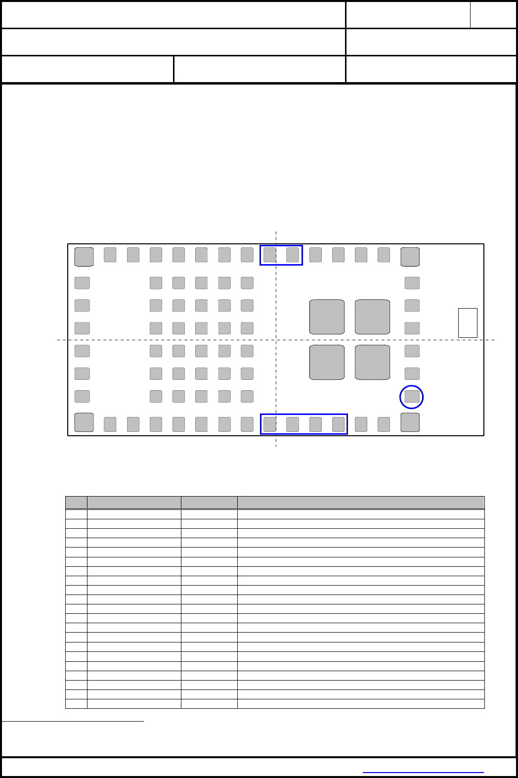
10.1. PAN9320 / PAN9310 TERMINAL LAYOUT
Top View, Application PCB
PAN9310 RF bottom pad is marked with a blue circle
Command UART0 (2 pads) and binary data UART1 (4 pads) are marked with a blue rectangular box
36 22
Top View
151
16
17
18
19
20
21
42
41
40
39
38
37
Chip
Antenna
F1 F2 F3 F4 F5
E1 E2 E3 E4 E5
D1 D2 D3 D4 D5
C1 C2 C3 C4 C5
B1 B2 B3 B4 B5
A1 A2 A3 A4 A5
2 3 4 5 6 7 8 9 10 11 12 13 14
35 34 33 32 31 30 29 28 27 26 25 24 23
GND
THERMO GND
THERMO
GND
THERMO GND
THERMO
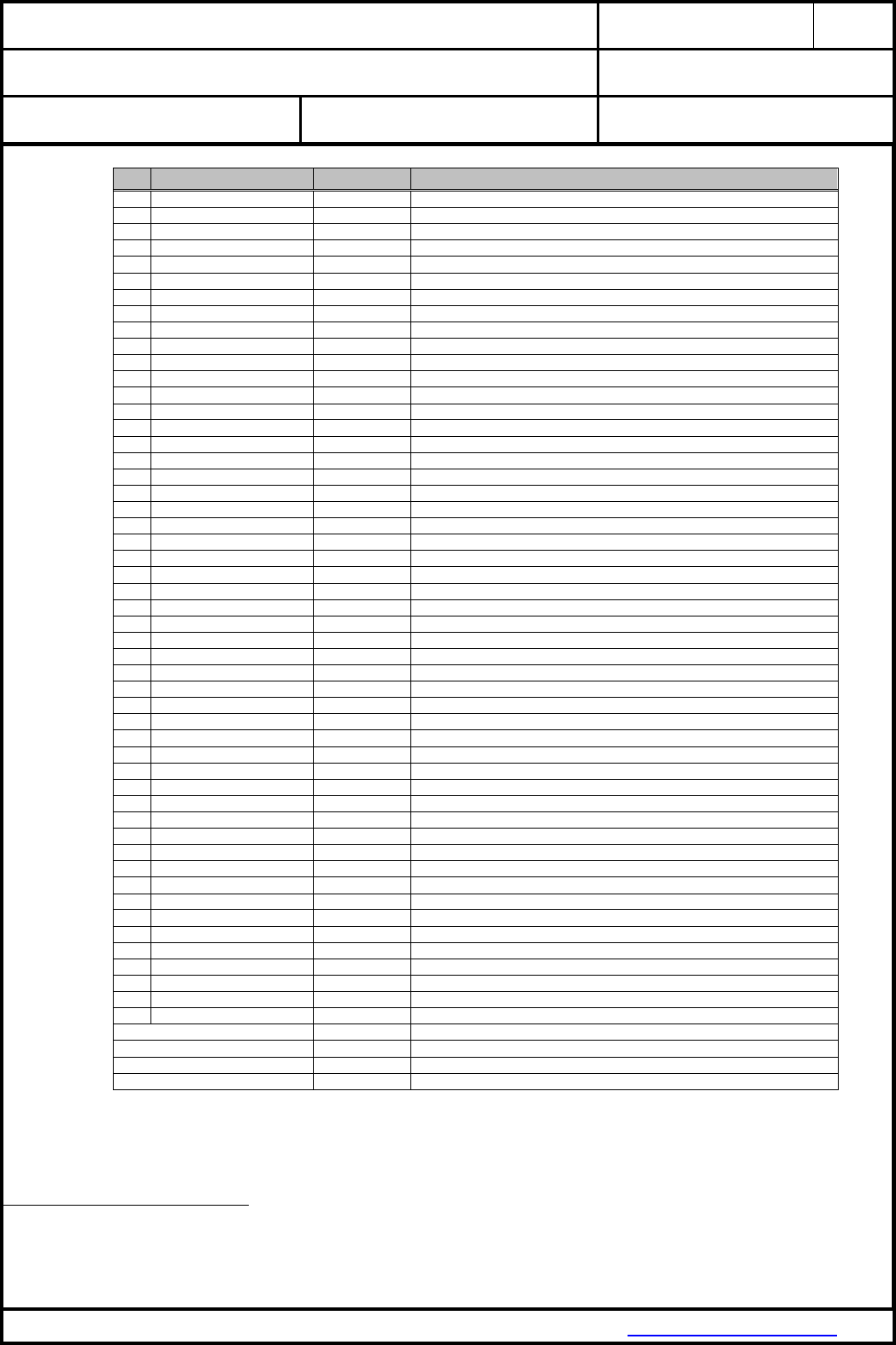
10.2. COMMON TERMINAL PIN-CONFIGURATION
No
Pin Name
Pin Type
Description
1
GND
Ground Pin
Connect to Ground
2
GPIO44 1
Digital I/O
Digital I/O #44
3
GPIO45 1
Digital I/O
Digital I/O #45
4
USB AVDD 33
Power
Don’t connect, only for internal purpose
5
NC
NC
Don’t connect
6
NC
NC
Don’t connect
7
3.3V
Power
3.0V – 3.6V power supply connection (typical 3.3V)
8
3.3V
Power
3.0V – 3.6V power supply connection (typical 3.3V)
9
UART1 CTS
Digital In
CTSn for UART1 (using hardware flow control)
10
UART1 RTS
Digital Out
RTSn for UART1 (using hardware flow control)
11
UART1 TXD
Digital Out
TXD for UART1
12
UART1 RXD
Digital In
RXD for UART1
13
QSPI CS2 4
Digital Out
Chip select external flash (connect for usage of external QSPI flash memory)
14
GND
Ground Pin
Connect to Ground
15
GND
Ground Pin
Connect to Ground
16
NC / RF
NC / Analog IO
PAN9320: NC / PAN9310: RF in/out over 50 bottom pad
17
GND
Ground Pin
Connect to Ground
18
GND
Ground Pin
Connect to Ground
19
GND
Ground Pin
Connect to Ground
20
GND
Ground Pin
Connect to Ground
21
GND
Ground Pin
Connect to Ground
1
All GPIO’s are initially set to output with low level
CLASSIFICATION
PRODUCT SPECIFICATION
No.
DS-9320-2400-102
REV.
1.1
SUBJECT
WI-FI IEEE 802.11 BGN FULL EMBEDDED MODULE
PAGE
9 of 43
CUSTOMER’S CODE
PAN9320 / PAN9310
PANASONIC’S CODE
ENW49A01x3EF & ENW49A02x3EF
DATE
14.03.2016
PANASONIC INDUSTRIAL DEVICES EUROPE GMBH
www.pideu.panasonic.de
No
Pin Name
Pin Type
Description
22
GND
Ground Pin
Connect to Ground
23
GND
Ground Pin
Connect to Ground
24
GND
Ground Pin
Connect to Ground
25
GND
Ground Pin
Connect to Ground
26
W STAT LED
Digital Out
Connect to LED wireless (WLAN) status, active low
27
UART0 TXD / DUAL STAT
Digital Out
TXD for UART0 / UART1 state (binary data or command)
28
UART0 RXD / DUAL SW
Digital In
RXD for UART0 / UART1 toggle switch for controlling the state
29
GPIO4 1
Digital I/O
Digital I/O #4
30
GPIO5 1
Digital I/O
Digital I/O #5
31
GPIO6 1
Digital I/O
Digital I/O #6
32
GPIO7 1
Digital I/O
Digital I/O #7
33
STAT LED1
Digital Out
Connect to LED MCU status (heartbeat), active low
34
STAT LED2
Digital Out
Connect to LED IP-Connectivity (allocated IP), active low
35
STAT LED3
Digital Out
Connect to LED Error (active during booting), active low
36
GND
Ground Pin
Connect to Ground
37
RESETn
Digital In
Reset MCU, active low (also option for flashing in production process)
38
WAKE UP0
Digital In
Don’t connect, only for internal purpose
39
BOOT
Digital In
Boot option, high level boot from internal flash memory 2
40
GPIO28 1
Digital I/O
Digital I/O #28
41
MCU READY
Digital Out
Connect to LED MCU ready (booting ready), active high
42
FACTORY RESET
Digital In
Factory reset (valid after 10 seconds), active high
A1
NC
NC
Don’t connect
A2
NC
NC
Don’t connect
A3
NC
NC
Don’t connect
A4
NC
NC
Don’t connect
A5
NC
NC
Don’t connect
B1
NC
NC
Don’t connect
B2
BT FREQ
Input Signal
Information BT using channel which overlaps WLAN channel or not
B3
BT GRANTN
Output Signal
Indicate permission to transmit, low BT can transmit
B4
BT REQ
Input Signal
BT device request access to medium
B5
BT STATE
Input Signal
Information BT_REQ priority (1- or 2-bit) and direction BT RX/TX
C1
NC
NC
Don’t connect
C2
NC
NC
Don’t connect
C3
WAKE UP1 3
Digital In
Wake up signal for WLAN SoC (Host-to-SoC), active high 3
C4
QSPI CLK 4
Digital Out
Clock for QSPI (connect for usage of external QSPI flash memory)
C5
QSPI D3 4
Digital I/O
Data3 for QSPI (connect for usage of external QSPI flash memory)
D1
TDI
Digital In
TDI for JTAG (option for flashing in production process)
D2
TRSTn
Digital In
TRSTn for JTAG (option for flashing in production process)
D3
NC
NC
Don’t connect
D4
QSPI D0 4
Digital I/O
Data0 for QSPI (connect for usage of external QSPI flash memory)
D5
QSPI D1 4
Digital I/O
Data1 for QSPI (connect for usage of external QSPI flash memory)
E1
TDO
Digital Out
TDO for JTAG (option for flashing in production process)
E2
TCK
Digital Out
TCK for JTAG (option for flashing in production process)
E3
TMS
Digital I/O
TMS for JTAG (option for flashing in production process)
E4
QSPI D2 4
Digital I/O
Data2 for QSPI (connect for usage of external QSPI flash memory)
E5
QSPI CS 4
Digital Out
Don’t connect, only for internal purpose
F1
W PDn
Digital In
Don’t connect, only for internal purpose (pull-up resistor internally)
F2
W RESETn
Input Signal
Don’t connect, only for internal purpose (pull-up resistor internally)
F3
GND
Ground Pin
Connect to Ground
F4
GND
Ground Pin
Connect to Ground
F5
GND
Ground Pin
Connect to Ground
GND THERMO
Thermal Pin
Connect to Ground
GND THERMO
Thermal Pin
Connect to Ground
GND THERMO
Thermal Pin
Connect to Ground
GND THERMO
Thermal Pin
Connect to Ground
2
Connect the BOOT pin over a 100 Ohm resistor to VCC
3
Connect to HOST MCU (wake up after shut-off mode, active high), use 10 kOhm resistor to GND at pin
4
Connect only in case of using external QSPI flash memory, otherwise do not connect

CLASSIFICATION
PRODUCT SPECIFICATION
No.
DS-9320-2400-102
REV.
1.1
SUBJECT
WI-FI IEEE 802.11 BGN FULL EMBEDDED MODULE
PAGE
10 of 43
CUSTOMER’S CODE
PAN9320 / PAN9310
PANASONIC’S CODE
ENW49A01x3EF & ENW49A02x3EF
DATE
14.03.2016
PANASONIC INDUSTRIAL DEVICES EUROPE GMBH
www.pideu.panasonic.de
11. GENERAL FEATURES
Surface Mount Type (SMT) measured 29.0 x 13.5 x 2.66 mm³
Wireless Local Area Network (WLAN) module with integrated MCU and Radio
Supports IEEE 802.11 b/g/n in the 2.4 GHz ISM band
TX power up to +18dBm (for IEEE 802.11b)
Outstanding RX sensitivity -98dBm (for IEEE 802.11b DSSS 1Mbps)
Marvell® 88W8782 WLAN System-on-Chip (SoC) and 88MC200 (MCU) inside
Two internal crystal oscillators with 32MHz and 40MHz
HOST communication interfaces UART0 (command) and UART1 (binary data)
Integrated TCP/IP network stack: IPv4, ARP, and AutoIP
UDP Name Services: DHCP, DNS, mDNS, and DNS-SD
HTTP(s) server with AJAX technology using JavaScript (JSON)
HTTP(s) client for integrated cloud communication
SMTP(s) client for E-Mail notifications
TLS1.2 security with user / group authentication including X.509 Certificate
802.11 supplicant: WEP, WPA, WPA2, and WPA2 mixed mode
Wireless update of radio driver and MCU firmware with integrated boot loader
Integrated QSPI flash memory for customer web contents up to 1 Mbyte (externally extendable)
Evaluation and development software available for Windows
Getting started tutorials, libraries, and APIs
Easy-To-Use (ETU) evaluation board for quick development and reduced time to market
Programming over standard JTAG
Shielding to resist EMI
12. HOST INTERFACES
12.1. UART0 INTERFACE
2-wire data transfer (RX, TX)
Programmable baud rate (300 bps to 1.5 Mbps)
Data format (LSB first)
Data bit: (5-8 bit)
Parity bit: (0-4 bit)
Stop bit: (1-2 bit)
12.2. UART1 INTERFACE
4-wire data transfer (RX, TX, RTS, CTS)
Programmable baud rate (300 bps to 1.5 Mbps)
Data format (LSB first)
Data bit: (5-8 bit)
Parity bit: (0-4 bit)
Stop bit: (1-2 bit)

CLASSIFICATION
PRODUCT SPECIFICATION
No.
DS-9320-2400-102
REV.
1.1
SUBJECT
WI-FI IEEE 802.11 BGN FULL EMBEDDED MODULE
PAGE
11 of 43
CUSTOMER’S CODE
PAN9320 / PAN9310
PANASONIC’S CODE
ENW49A01x3EF & ENW49A02x3EF
DATE
14.03.2016
PANASONIC INDUSTRIAL DEVICES EUROPE GMBH
www.pideu.panasonic.de
13. PERIPHERAL BUS INTERFACE
Embedded WLAN Radio (SoC) with following features:
Clocked Serial Unit (CSU)
3-Wire, 4-Wire (3W4W) Interface
2-Wire Serial Interface (TWSI)
1-Wire Serial Interface
General-Purpose I/O (GPIO) Interface
Defined GPIOs, I/O configured to either input or output
GPIO “W STAT LED” with LED output functionality
LED pulse stretching to observe short duration of status events
Two software controlled blink rates to indicate events
Embedded MCU with following features:
JTAG
Standard JTAG interface
Quad Serial Peripheral Interface
Integrated QSPI controller (master) with synchronous serial peripheral for slave
device connection
Integrated QSPI slave device with allocated Firmware range and web content
16 Mbit / 2 Mbyte (1 Mbyte is reserved for customer web content)
256 byte per programmable page with configurable length 1 to 256
Uniform sector erase (4 Kbytes)
Uniform block erase (64 Kbytes)
Erase/Program suspend and resume
Standard / Dual / Quad SPI Support
Flash controller for fetching code or read-only data
200 Mbps max. serial data rate in quad mode with 50 MHz functional clock
Chip Select (CS2) for parallel operation of module internal and external QSPI flash
External QSPI slave device can be connected for customer web content memory
extension
Macronix QSPI flash MX25L1633E is supported
Maximum 16Mbit / 2MByte is supported by firmware
Wake Up
External signal for HOST-to-SoC wake-up after shut-off mode
General-Purpose I/O (GPIO) interface
Defined GPIOs, I/O configured to either input or output (on/off)
GPIOs with LED status functionality (Ready, Heartbeat, IP-Connectivity and Error)

CLASSIFICATION
PRODUCT SPECIFICATION
No.
DS-9320-2400-102
REV.
1.1
SUBJECT
WI-FI IEEE 802.11 BGN FULL EMBEDDED MODULE
PAGE
12 of 43
CUSTOMER’S CODE
PAN9320 / PAN9310
PANASONIC’S CODE
ENW49A01x3EF & ENW49A02x3EF
DATE
14.03.2016
PANASONIC INDUSTRIAL DEVICES EUROPE GMBH
www.pideu.panasonic.de
14. WLAN FEATURES
14.1. IEEE 802.11 / STANDARDS
802.11 data rates 1 and 2 Mbps (DSSS)
802.11b data rates 5.5 and 11 Mbps (CCK)
802.11g data rates 6, 9, 12, 18, 24, 36, 48 and 54 Mbps (OFDM)
802.11b/g performance enhancements
802.11n compliant with maximum data rates up to 72 Mbps (20 MHz channel) and
150 Mbps (40 MHz channel)
802.11d international roaming
5
802.11i enhanced security (WEP, WPA, WPA2)
802.11k radio resource measurement
5
802.11r fast hand-off for AP roaming
5
802.11w protected management frames
5
Support clients (stations) implementing IEEE Power Save mode
14.2. WLAN MAC
Ad-Hoc
5 and Infrastructure Modes
RTS/CTS for operation und DCF
Hardware filtering of 32 multicast addresses and duplicate frame detection for up to 32 unicast
addresses
WLAN SoC with TX and RX FIFO for maximum throughput
Open System and Shared Key Authentication services
A-MPDU RX (de-aggregation) and TX (aggregation)
20/40 MHz channel coexistence
Reduced Inter-Frame Spacing (RIFS) bursting
Management Information Base (MIB) counter
Radio resource measurement counters
Block acknowledgement with 802.11n extensions
Transmit beam former support
Transmit rate adaptation
Transmit power control
Long and short preamble generation on a frame-by-frame basis for 802.11b frames
Marvell® Mobile Hotspot technology (MMH)
14.3. WLAN BASEBAND
802.11n 1x1 SISO (WLAN SoC with SISO RF radio)
Backward compatibility with legacy 802.11b/g technology
PHY data rates up to 150 Mbps (802.11n - MCS7)
20 MHz bandwidth/channel, 40 MHz bandwidth/channel, upper/lower 20 MHz bandwidth in 40
MHz channel and 20 MHz duplicate legacy bandwidth in 40 MHz channel mode operation
Modulation and Coding Scheme MCS 0 ~ 7 and MCS 32 (duplicate 6 Mbps)
Radio resource measurement
Optional 802.11n SISO features:
20/40 MHz coexistence
1-stream Space-Time-Block-Coding (STBC) reception
Short Guard Interval
RIFS on receive path
Beamformer function and hardware acceleration
Greenfield TX/RX
5
Hardware supported, not implemented in the pre-installed firmware stack

CLASSIFICATION
PRODUCT SPECIFICATION
No.
DS-9320-2400-102
REV.
1.1
SUBJECT
WI-FI IEEE 802.11 BGN FULL EMBEDDED MODULE
PAGE
13 of 43
CUSTOMER’S CODE
PAN9320 / PAN9310
PANASONIC’S CODE
ENW49A01x3EF & ENW49A02x3EF
DATE
14.03.2016
PANASONIC INDUSTRIAL DEVICES EUROPE GMBH
www.pideu.panasonic.de
14.4. WLAN RADIO
20 and 40 MHz channel bandwidth
Embedded WLAN Radio SoC with following features:
Direct conversion radio (no SAW filter)
2.4GHz TX/RX switch, Power Amplifier (PA) and Low Noise Amplifier (LNA) path
Gain selectable LNAs with optimized noise figure and power consumption
Power Amplifiers with power control
Closed loop power control (0.5 dB step increments)
Optimized TX gain distribution for linearity and noise performance
Fine channel step with AFC (adaptive frequency control)
14.5. WLAN ENCRYPTION
Embedded WLAN Radio SoC with following features:
WEP 64-bit and 128-bit encryption with hardware TKIP processing (WPA)
AES-CCMP hardware implementation as part of 802.11i security standard (WPA2)
Enhanced AES engine performance
AES-Cipher-Based Message Authentication Code (CMAC) as part of the 802.11w security
standard
5

CLASSIFICATION
PRODUCT SPECIFICATION
No.
DS-9320-2400-102
REV.
1.1
SUBJECT
WI-FI IEEE 802.11 BGN FULL EMBEDDED MODULE
PAGE
14 of 43
CUSTOMER’S CODE
PAN9320 / PAN9310
PANASONIC’S CODE
ENW49A01x3EF & ENW49A02x3EF
DATE
14.03.2016
PANASONIC INDUSTRIAL DEVICES EUROPE GMBH
www.pideu.panasonic.de
15. BLOCK DIAGRAM
15.1. PAN9320
15.2. PAN9310
CLASSIFICATION
PRODUCT SPECIFICATION
No.
DS-9320-2400-102
REV.
1.1
SUBJECT
WI-FI IEEE 802.11 BGN FULL EMBEDDED MODULE
PAGE
15 of 43
CUSTOMER’S CODE
PAN9320 / PAN9310
PANASONIC’S CODE
ENW49A01x3EF & ENW49A02x3EF
DATE
14.03.2016
PANASONIC INDUSTRIAL DEVICES EUROPE GMBH
www.pideu.panasonic.de
16. KEY PARTS LIST
Part Name
Material
P.W.Board
Glass cloth epoxy resin with gold plating
Casing
Material: C7521, thickness 0.30mm
IC (WLAN SoC)
88W8782 (Marvell®, www.marvell.com)
IC (Microcontroller Unit)
88MC200 (Marvell®, www.marvell.com)
IC (QSPI flash memory)
MX25L1633E (Macronix®, http://www.macronix.com)
17. TEST CONDITIONS
Measurements shall be made under operating free-air temperature range unless otherwise specified.
Temperature 25 ± 10°C
Humidity 40 to 85%RH
Supply Voltage 3.3V
18. GENERAL REQUIREMENTS AND OPERATION
All specifications are over temperature and process, unless indicated otherwise.
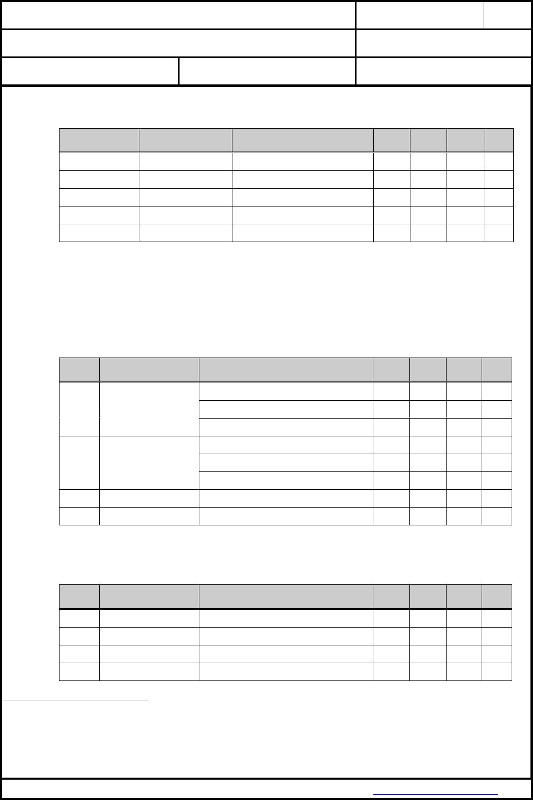
18.1. ABSOLUTE MAXIMUM RATINGS
The maximum ratings may not be exceeded under any circumstances, not even momentarily and
individually, as permanent damage to the module will result.
Symbol
Parameter
Condition
Min.
Typ.
Max.
Units
TSTOR
Storage temperature
-40
+85
°C
VESD
ESD robustness
All pads, according to human-body model, JEDEC
STD 22, method A114
1000
V
According to charged-device model, JEDEC STD 22,
method C101
500
V
PRF
RF input level
+20
dBm
VDDMAX
Maximum voltage
Maximum power supply voltage from any pin with
respect to VSS (GND)
-0.3
3.6
V
VDIG
Voltage on any digital pins
GPIOs, RESETn, UART, QSPI, Coex I/F
-0.3
VDDMAX
V
18.2. RECOMMENDED OPERATING CONDITIONS
The maximum ratings may not be exceeded under any circumstances, not even momentarily and
individually, as permanent damage to the module will result.
Symbol
Parameter
Condition
Min.
Typ.
Max.
Units
TA
Ambient operating
temperature range
Extended grade
-30
+70
°C
VDD
3V3 Supply voltage 6
Voltage on pins 7, 8 (3.3V)
I/O supply voltage internally connected to VDD / VCC
3.0
3.3
3.6
V
6
The supply current must be limited to max. 1A
CLASSIFICATION
PRODUCT SPECIFICATION
No.
DS-9320-2400-102
REV.
1.1
SUBJECT
WI-FI IEEE 802.11 BGN FULL EMBEDDED MODULE
PAGE
16 of 43
CUSTOMER’S CODE
PAN9320 / PAN9310
PANASONIC’S CODE
ENW49A01x3EF & ENW49A02x3EF
DATE
14.03.2016
PANASONIC INDUSTRIAL DEVICES EUROPE GMBH
www.pideu.panasonic.de
18.3. DIGITAL PIN CHARACTERISTICS
Symbol
Parameter
Condition
Min.
Typ.
Max.
Units
VIH
High level input voltage 7
3.3V Operation (VIO = VDD)
0.7VDD
VDD+0.3
V
VIL
Low level input voltage 7
3.3V Operation (VIO = VDD)
-0.3
0.3VDD
V
IPS @ 0.5VDD
Pull-up / down strength
VDigital Pin=0.5 x VDD
10
50
µA
IOH @ VDD-0.4V
High level output current 7
3.3V Operation (VIO = VDD)
4
8
mA
IOL @ 0.4V
Low level output current 7
3.3V Operation (VIO = VDD)
4
8
mA
18.4. ELECTRICAL CHARACERISTICS
The current consumption depends on the user scenario and the setup and timing in the power modes.
Assume VDD = 3.3V, Tamb = 25°C if nothing else stated
18.4.1. Current Consumption
Symbol
Parameter
Condition
Min.
Typ.
Max.
Units
ITX
Active Transmit 8
PTX = +18 dBm for 802.11b @ 11 Mbps
430
mA
PTX = +15 dBm for 802.11g @ 54 Mbps
370
mA
PTX = +13 dBm for 802.11n (20MHz) @ 65 Mbps
350
mA
IRX
Active Receive 9
802.11b @ 11 Mbps
150
mA
802.11g @ 54 Mbps
155
mA
802.11n @ 65 Mbps
160
mA
IRXIdle
Receive Idle 10
Passive receive state, ready to receive packets, but
no active decoding
145
mA
IShut-off
Shut-off
MCU and Radio in shut-off mode
27
mA
18.5. INTERNAL OPERATING FREQUENCIES
Symbol
Parameter
Condition
Min.
Typ.
Max.
Units
fSYSCLK1
CPU/System/Encryption
clock speed
Refers to clock speed of WLAN SoC
128
MHz
fSYSCLK2
CPU/System clock speed
Refers to clock speed of MCU
200
MHz
fREFCLK1
WLAN SoC Crystal
fundamental frequency
Frequency tolerance < ±10 ppm over operating
temperature and process
40
MHz
fREFCLK2
Microcontroller Crystal
fundamental frequency
Frequency tolerance < ±10 ppm over operating
temperature and process
32
MHz
7
The capacitive load should not be larger than 50 pF for all I/O’s when using the default driver strength settings. Generally, large capacitance loads increase the overall current
consumption.
8
Peak values for specified output power level and data rate with UDP traffic between the AP and Device (STA).
9
Peak values for specified data rate with UDP traffic between the AP and Device (STA)..
10
The device is powered on and is ready to receive packets, but is not actively decoding.
CLASSIFICATION
PRODUCT SPECIFICATION
No.
DS-9320-2400-102
REV.
1.1
SUBJECT
WI-FI IEEE 802.11 BGN FULL EMBEDDED MODULE
PAGE
17 of 43
CUSTOMER’S CODE
PAN9320 / PAN9310
PANASONIC’S CODE
ENW49A01x3EF & ENW49A02x3EF
DATE
14.03.2016
PANASONIC INDUSTRIAL DEVICES EUROPE GMBH
www.pideu.panasonic.de
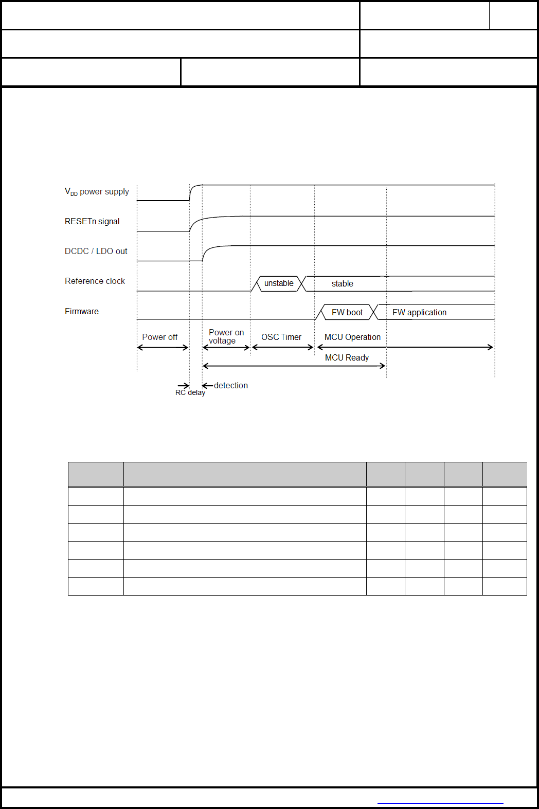
18.6. POWER UP SEQUENCE
When the power is turned on, set reset signal to low (RESETn = low). After the VDD is stable, release
the reset (RESETn = high).
18.7. FIRMWARE RELATED TIMING
Symbol
Parameter
Min.
Typ.
Max.
Units
T MCU READY
Time period from Power up or Reset until MCU READY pin is active
4
5
sec
T WAKE UP
Time period need to set pin active to wake-up from shut-off mode
(afterwards firmware is booting)
100
ms
T FACTORY RESET
Time period need to set pin active to release factory reset
(afterwards firmware is booting)
8
10
sec
T INFRA ASSO
Time period in Infrastructure mode from WLAN association request until
association with selected Access-Point’s SSID
4
sec
T DE-ASSO SCAN
Time period between de-association from AP until next scan is released
60
sec
T IP DHCP
Time period from IP DHCP request until IP assignment
90
sec
CLASSIFICATION
PRODUCT SPECIFICATION
No.
DS-9320-2400-102
REV.
1.1
SUBJECT
WI-FI IEEE 802.11 BGN FULL EMBEDDED MODULE
PAGE
18 of 43
CUSTOMER’S CODE
PAN9320 / PAN9310
PANASONIC’S CODE
ENW49A01x3EF & ENW49A02x3EF
DATE
14.03.2016
PANASONIC INDUSTRIAL DEVICES EUROPE GMBH
www.pideu.panasonic.de
18.8. COEXISTENCE INTERFACE SPECIFICATION
The Coexistence Interface pins are powered from the VIO voltage supply internally connected to
VDD = 3.3V. See Chapter 18.3 Digital Pin Characteristics for DC specification.
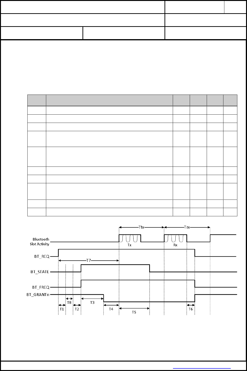
18.8.1. Marvell® 3/4-Wire Timing Data
Symbol
Parameter
Min.
Typ.
Max.
Units
T1
Priority[0] info is valid in BT_STATE on and after T1 from BT_REQ rise.
0
1
100
µs
T2
TxRx Info is valid in BT_STATE on and after T2. The BT_STATE must hold until
there is any change of direction in the next slots.
2
19
100
µs
T3
Time from TxRx Info valid to BCA grant decision (T3 = T7 – T4 – T2 – T8 – T1).
2
40
594
µs
T4
BT_GRANTn needs to be valid T4 time before the upcoming slot. BT_GRANTn
indicates Tx grant, and may also indicate Rx grant. Once a slot is granted, the
subsequent slots are also granted unless there is a change in direction from Rx to
Tx. Rx to Tx change always re-arbitrates.
2
80
594
µs
T5
TxRx Info for the next slot is valid on and after T5 to the start of the next slot. If
direction remains the same for the next slot, then BT_STATE must not change
during the current slot. If the direction changes for the next slot, the BT_STATE
must change only after the last bit of Bluetooth data is transferred; otherwise the
transfer may be disrupted.
5
40
600
µs
T6
The BT_REQ signal de-asserts T6 time after last bit of Bluetooth data is transferred.
0
15
25
µs
T7
Time from BT_REQ rise to first Bluetooth slot boundary. Bluetooth slot boundary is
marked by first bit of Bluetooth data.
8
150
600
µs
T8
Optional
Priority[1] information is valid in BT_STAT on and after T8. This time parameter only
exists if BCA is configured for 2-bit priority on same BT_STATE pin. Otherwise, the
start of T2 would come after T1.
2
10
100
µs
Ttx
Slot time (fixed fpr Bluetooth)
625
µs
Trx
Slot time (fixed fpr Bluetooth)
625
µs
CLASSIFICATION
PRODUCT SPECIFICATION
No.
DS-9320-2400-102
REV.
1.1
SUBJECT
WI-FI IEEE 802.11 BGN FULL EMBEDDED MODULE
PAGE
19 of 43
CUSTOMER’S CODE
PAN9320 / PAN9310
PANASONIC’S CODE
ENW49A01x3EF & ENW49A02x3EF
DATE
14.03.2016
PANASONIC INDUSTRIAL DEVICES EUROPE GMBH
www.pideu.panasonic.de
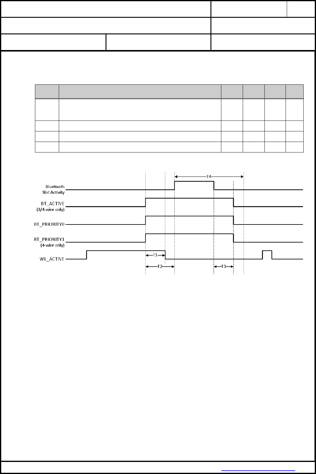
18.8.2. WL_ACTIVE 2/3/4-Wire Timing Data
Symbol
Parameter
Min.
Typ.
Max.
Units
T1
If WLAN can be stopped, WL_ACTIVE will de-asser prior to Bluetooth slot start
(T1 < T2)
If the Bluetooth device samples WL_ACTIVE before starting priority transfer,
WL_ACTIVE needs to de-assert earlier than the sampling time.
0
499
µs
T2
Time from BT_PRIORITY rise to start of Bluetooth activity.
20
50
499
µs
T3
Time from end of Bluetooth activity to BT_PRIORITY fall.
0
0
499
µs
T4
Slot time (fixed fpr Bluetooth)
625
µs
CLASSIFICATION
PRODUCT SPECIFICATION
No.
DS-9320-2400-102
REV.
1.1
SUBJECT
WI-FI IEEE 802.11 BGN FULL EMBEDDED MODULE
PAGE
20 of 43
CUSTOMER’S CODE
PAN9320 / PAN9310
PANASONIC’S CODE
ENW49A01x3EF & ENW49A02x3EF
DATE
14.03.2016
PANASONIC INDUSTRIAL DEVICES EUROPE GMBH
www.pideu.panasonic.de
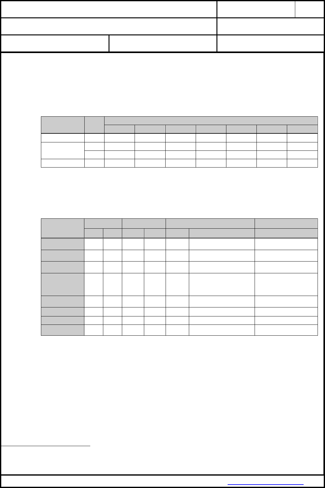
18.9. HOST INTERFACE SPECIFICATION
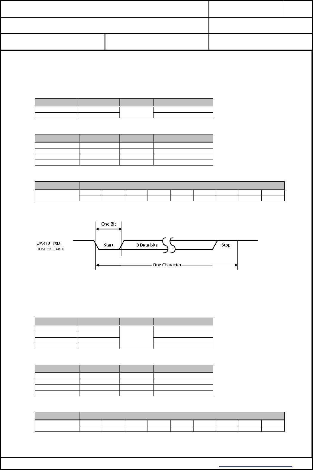
18.9.1. UART0 Command Interface
UART0 command interface bus signals:
Module Pin No
Signal Name
Function
Description
27
UART0 TXD
Command
Transmit data output
28
UART0 RXD
Receive data input
Protocol:
Item
Range
Default
Comment
Baudrate
300 ~ 1500000
115200
Data Bits
5 ~ 8 (LSB first)
8
LSB first
Parity Bits
0 ~ 4
0
Stop Bit
1 / 1,5 / 2
1
Supported Baud Rates:
Item
Baud
Baudrate
300
600
1200
4800
9600
14400
19200
28800
38400
56000
57600
115200
128000
256000
520000
780000
1500000
UART0 timing diagram:
18.9.2. UART1 Binary Data Interface
UART1 binary data interface bus signals:
Module Pin No
Signal Name
Function
Description
9
UART1 CTS
Binary data
Clear to send
10
UART1 RTS
Request to send
11
UART1 TXD
Transmit data output
12
UART1 RXD
Receive data input
Protocol:
Item
Range
Default
Comment
Baudrate
300 ~ 1500000
115200
Data Bits
5 ~ 8 (LSB first)
8
LSB first
Parity Bits
0 ~ 4
0
Stop Bit
1 / 1,5 / 2
1
Supported Baud Rates:
Item
Baud
Baudrate
300
600
1200
4800
9600
14400
19200
28800
38400
56000
57600
115200
128000
256000
520000
780000
1500000
CLASSIFICATION
PRODUCT SPECIFICATION
No.
DS-9320-2400-102
REV.
1.1
SUBJECT
WI-FI IEEE 802.11 BGN FULL EMBEDDED MODULE
PAGE
21 of 43
CUSTOMER’S CODE
PAN9320 / PAN9310
PANASONIC’S CODE
ENW49A01x3EF & ENW49A02x3EF
DATE
14.03.2016
PANASONIC INDUSTRIAL DEVICES EUROPE GMBH
www.pideu.panasonic.de
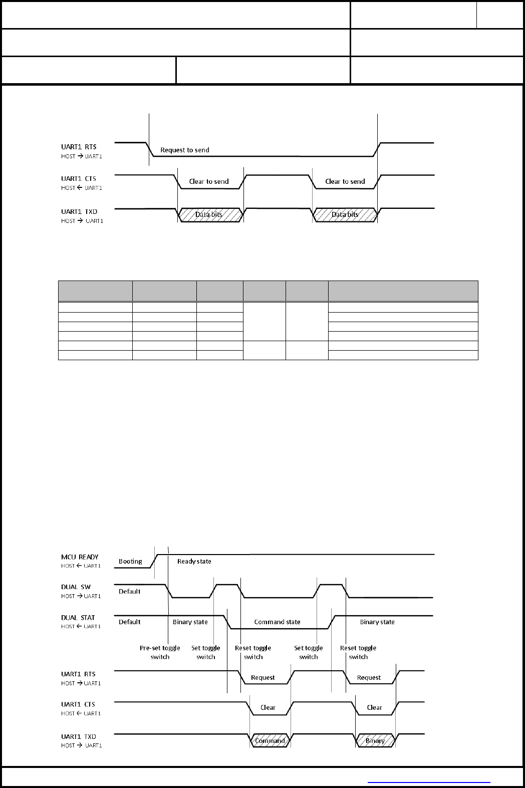
UART1 timing diagram:
18.9.3. UART1 Dual Interface
UART1 dual interface bus signals:
Module Pin No
Signal Name
GPIO
definition
GPIO level
default
State
default
Description
9
UART1 CTS
OUT
-
-
Clear to send
10
UART1 RTS
IN
Request to send
11
UART1 TXD
IN
Transmit data output
12
UART1 RXD
OUT
Receive data input
27
DUAL STAT
OUT
HIGH
Binary data
UART1 state condition (binary or command)
28
DUAL SW
IN
UART1 toggle switch for binary / command
See Chapter 18.9.2 UART1 Binary Data Interface for specification of protocol and supported baud
rates.
The usage of the UART1 dual interface needs to be configured at the customer content of firmware.
After booting the MCU READY pin is changing from low to high level. For start condition the DUAL SW
input pin needs to be pre-set from the HOST by changing from high to low level. The DUAL STAT
output pin is signalling high level as Binary state. In this case the HOST is able to transmit or receive
binary data. To change from Binary to Command state the DUAL SW input pin needs to be toggled
(low - high - low level change) from the HOST: 1. The change of state is initiated by changing the
DUAL SW input pin from low to high level (set toggle switch). 2. After the DUAL STAT pin is changing
the state from high to low level the Command state is active and the DUAL SW input pin can be reset
from high to low level (reset toggle). 3. The HOST is now able to send commands. After the commands
are sent it is recommended to change back to Binary state by toggling the DUAL SW input pin again.
UART1 dual interface bus and control timing diagram:
CLASSIFICATION
PRODUCT SPECIFICATION
No.
DS-9320-2400-102
REV.
1.1
SUBJECT
WI-FI IEEE 802.11 BGN FULL EMBEDDED MODULE
PAGE
22 of 43
CUSTOMER’S CODE
PAN9320 / PAN9310
PANASONIC’S CODE
ENW49A01x3EF & ENW49A02x3EF
DATE
14.03.2016
PANASONIC INDUSTRIAL DEVICES EUROPE GMBH
www.pideu.panasonic.de
18.10. PERIPHERAL INTERFACE SPECIFICATION
The Peripheral Interface pins are powered from the VIO voltage supply internally connected to
VDD = 3.3V. See Chapter 18.3 Digital Pin Characteristics for DC specification.
18.10.1. Configurable GPIOs
GPIO function
GPIO pin name
State
GPIO4
GPIO5
GPIO6
GPIO7
GPIO28
GPIO44
GPIO45
Input IN
-
YES
YES
YES
YES
YES
YES
YES
Output OUT
ON
YES
YES
YES
YES
YES
YES
YES
OFF
YES
YES
YES
YES
YES
YES
YES
Default by firmware
OFF
OUT
OUT
OUT
OUT
OUT
OUT
OUT
The function of the configurable GPIOs are set by firmware default, but can be reconfigured by HOST
command interface (UART).
18.10.2. Firmware defined GPIOs
GPIO pin name
GPIO definition
GPIO level
Firmware state
Input
Output
Default
Active
Boot
Firmware application active
Firmware function
STAT LED1
NO
YES
-
LOW
OFF
OFF: Shut-off
BLINK (1sec): Firmware active
MCU Status (heartbeat)
STAT LED2
NO
YES
-
LOW
OFF
OFF: no IP assined
ON: IP assigned
IP-Connectivity
in Infrastructure mode
STAT LED3
NO
YES
-
LOW
ON
OFF: no error
ON: error appeared
MCU firmware error
W STAT LED
NO
YES
-
LOW
OFF
OFF: no AP connection
BLINK (0.3s): Scanning for AP
BLINK (1.2s): WLAN Error
ON: Associated with AP
WLAN connectivity in
Infrastructure mode
MCU READY
NO
YES
-
HIGH
OFF
OFF: Shut-off
ON: Firmware ready
Firmware application is ready
FACTORY RESET
YES
NO
LOW 11
HIGH
inactive
Set active for min. 10 seconds
Re-store firmware default
WAKE UP1
YES
NO
LOW 11
HIGH
inactive
Set active for min. 100 ms
Wake up after shut-off
BOOT
YES
NO
HIGH 12
HIGH
active
inactive after booting
Radio firmware to be loaded
from internal flash memory
The function of the firmware defined GPIOs are fixed and can’t be changed.
11
Set default level by using resistor with 10kOhm to GND
12
Set default level with resistor 100 Ohm to Vcc
CLASSIFICATION
PRODUCT SPECIFICATION
No.
DS-9320-2400-102
REV.
1.1
SUBJECT
WI-FI IEEE 802.11 BGN FULL EMBEDDED MODULE
PAGE
23 of 43
CUSTOMER’S CODE
PAN9320 / PAN9310
PANASONIC’S CODE
ENW49A01x3EF & ENW49A02x3EF
DATE
14.03.2016
PANASONIC INDUSTRIAL DEVICES EUROPE GMBH
www.pideu.panasonic.de
18.10.3. Quad Serial Peripheral Interface (QSPI)
18.10.3.1. List of supported Flash Memories
QSPI flash memory supported:
Parts Name
Manufacturer
Memory type
SPI Mode
SPI Clock
Memory size
Page size
MX25L1633E
Macronix
QSPI
1 / 2 / 4 I/O
104 / 85 MHz
16Mbit
256 byte
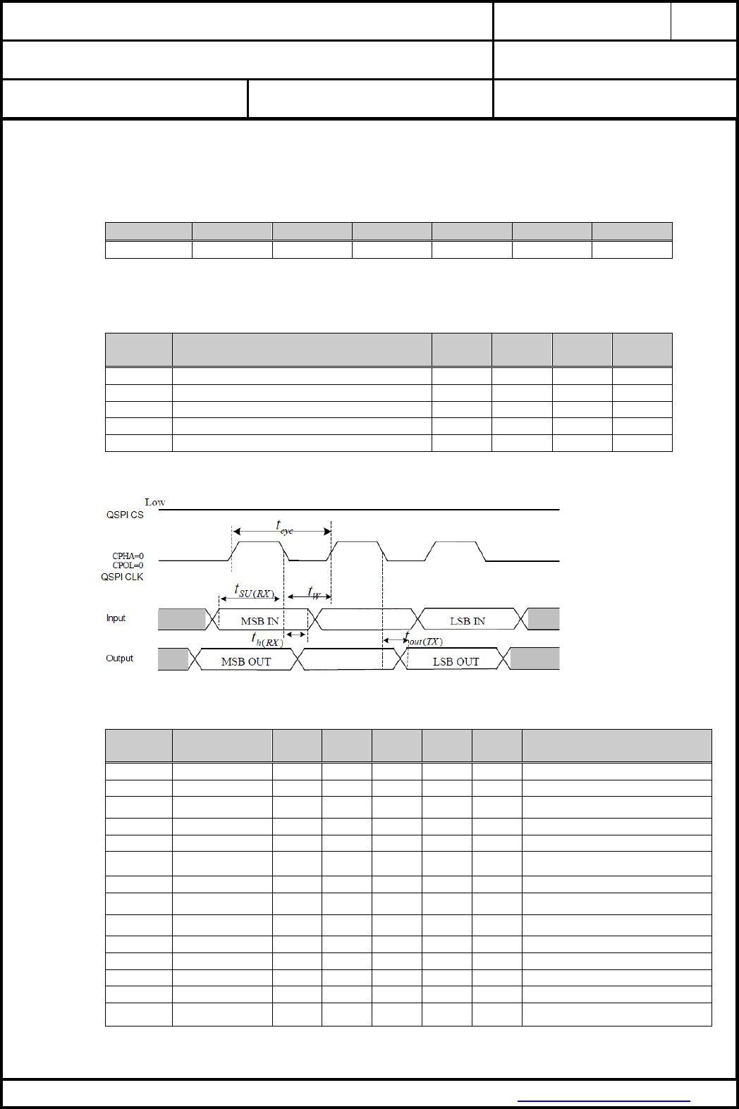
18.10.3.1. Firmware supported QSPI Characteristic
QSPI characteristic:
Symbol
Parameter
Min.
Typ.
Max.
Units
t cyc
QSPI clock cycle time
20
ns
t W
Clock high and low time
t cyc / 2-6.67
ns
t SU (RX)
Data input setup time
5.5
ns
t h (RX)
Data input hold time
0
ns
t out (TX)
Data output delay time
3.2
ns
QSPI timing diagram:
QSPI command set (used by firmware):
Command
Description
1st
byte
2nd
byte
3rd
byte
4th
byte
5th
byte
Action
WREN
Write enable
06 (hex)
sets the (WEL) write enable latch bit
WRDI
Write disable
04 (hex)
resets the (WEL) write enable latch bit
RDID
Read identification
9F (hex)
outputs JEDEC ID: 1-byte Manufacturer ID &
2-byte Device ID
RDSR
Read status register
05 (hex)
to read out the values of the status register
WRSR
Write status register
01 (hex)
Values
to write new values of the status register
READ
Read data
03 (hex)
AD1
A23-A16
AD2
A15-A8
AD3
A7-A0
n bytes read out until CS# goes high
FAST READ
Fast read data
0B (hex)
AD1
AD2
AD3
Dummy
n bytes read out until CS# goes high
2READ
2 I/O read
BB (hex)
ADD(2)
ADD(2) &
Dummy(2)
n bytes read out by 2 x I/O until CS# goes high
4READ
4 I/O read
EB (hex)
ADD(4) &
Dummy(4)
Dummy(4)
n bytes read out by 4 x I/O until CS# goes high
PP
Page program
02 (hex)
AD1
AD2
AD3
to program the selected page
4PP
Quad page program
38 (hex)
AD1
quad input to program the selected page
Sector Erase
4 KB sector erase
20 (hex)
AD1
AD2
AD3
to erase the selected sector
Block Erase
64 KB block ersae
D8 (hex)
AD1
AD2
AD3
to erase the selected block
Chip Erase
2 MB full chip erase
60 or C7
(hex)
to erase whole chip
CLASSIFICATION
PRODUCT SPECIFICATION
No.
DS-9320-2400-102
REV.
1.1
SUBJECT
WI-FI IEEE 802.11 BGN FULL EMBEDDED MODULE
PAGE
24 of 43
CUSTOMER’S CODE
PAN9320 / PAN9310
PANASONIC’S CODE
ENW49A01x3EF & ENW49A02x3EF
DATE
14.03.2016
PANASONIC INDUSTRIAL DEVICES EUROPE GMBH
www.pideu.panasonic.de
19. RF ELECTRICAL CHARACTERISTICS
19.1. WLAN RADIO SPECIFICATION
Parameter
Operation mode
Specification
Standard Conformance
IEEE 802.11 / IEEE 802.11b
IEEE 802.11g
IEEE 802.11n
Modulation
IEEE 802.11b
DSSS / CCK
IEEE 802.11g
OFDM
IEEE 802.11n
OFDM @ MCS0~7 and MCS32 (duplicate 6 Mbps)
Physical layer data rates
IEEE 802.11
1, 2 Mbps @ DSSS
IEEE 802.11b
5.5, 11 Mbps @ DSSS / CCK
Supported data rates
IEEE 802.11g
6, 9, 12, 18, 24, 36, 48, 54 Mbps
IEEE 802.11n
MCS0~7
HT20
LGI
6.5, 13, 19.5, 26, 39, 52, 58.5, 65 Mbps
SGI
7.2, 14.4, 21.7, 28.9, 43.3, 57.8, 65, 72.2 Mbps
HT40
LGI
13.5, 27, 40.5, 54, 81, 108, 121.5, 135 Mbps
SGI
15, 30, 45, 60, 90, 120, 135, 150 Mbps
Supported bandwidth
IEEE 802.11n
20, 40 MHz (BW)
Supported channel mode operation
IEEE 802.11n
20 MHz BW / channel, 40 MHz BW / channel,
upper / lower 20 MHz BW @ 40 MHz channel,
20 MHz duplicate legacy BW @ 40 MHz channel
Supported Guard Interval
IEEE 802.11n
400 ns (SGI), 800 ns (LGI)
Supported channel 2.4GHz 13
IEEE 802.11g
North America (US)
1, 2, 3, 4, 5, 6, 7, 8, 9, 10, 11
Canada (CA)
1, 2, 3, 4, 5, 6, 7, 8, 9, 10, 11
Europe (EU)
1, 2, 3, 4, 5, 6, 7, 8, 9, 10, 11, 12, 13
France (FR)
10, 11, 12, 13
Japan MMK (JP)
1, 2, 3, 4, 5, 6, 7, 8, 9, 10, 11, 12, 13
IEEE 802.11n
North America (US)
1-5, 2-6, 3-7, 4-8, 5-9, 6-10, 7-11
Canada (CA)
Europe (EU)
France (FR)
Japan MMK (JP)
-
13
In order to comply with relevant regulatory requirements, for the model’s supported channels please refer to the chapter 28. Ordering Information
CLASSIFICATION
PRODUCT SPECIFICATION
No.
DS-9320-2400-102
REV.
1.1
SUBJECT
WI-FI IEEE 802.11 BGN FULL EMBEDDED MODULE
PAGE
25 of 43
CUSTOMER’S CODE
PAN9320 / PAN9310
PANASONIC’S CODE
ENW49A01x3EF & ENW49A02x3EF
DATE
14.03.2016
PANASONIC INDUSTRIAL DEVICES EUROPE GMBH
www.pideu.panasonic.de
19.2. WLAN RF CHARACTERISTICS
19.2.1. RF Characteristics for IEEE 802.11b
Assume VDD = 3.3V, Tamb = 25°C if nothing else stated
50 Ohm terminal load connected to the RF connector
Parameter
Condition
Min.
Typ.
Max.
Units
RF frequency range
2400
2483.5
MHz
Carrier frequency tolerance
-25
+25
ppm
Transmit output power
+18
+20
dBm
Spectrum mask
fC ± 11 MHz
-30
dBr
fC ± 22 MHz
-50
Power-on / Power-down ramp
2
µs
RF Carrier suppression
-15
dB
Error Vector Magnitude (EVM)
Peak
35
%
Minimum Receive Sensitivity
1 Mbps (DSSS)
FER ≤ 8%
-98
-86
dBm
2 Mbps (DSSS)
FER ≤ 8%
-95
-83
dBm
5.5 Mbps (CCK)
FER ≤ 8%
-91
-79
dBm
11 Mbps (CCK)
FER ≤ 8%
-88
-76
dBm
Maximum Input Level
FER ≤ 8%
-10
dBm
Adjacent Channel Rejection
FER ≤ 8%
35
dB
CLASSIFICATION
PRODUCT SPECIFICATION
No.
DS-9320-2400-102
REV.
1.1
SUBJECT
WI-FI IEEE 802.11 BGN FULL EMBEDDED MODULE
PAGE
26 of 43
CUSTOMER’S CODE
PAN9320 / PAN9310
PANASONIC’S CODE
ENW49A01x3EF & ENW49A02x3EF
DATE
14.03.2016
PANASONIC INDUSTRIAL DEVICES EUROPE GMBH
www.pideu.panasonic.de
19.2.2. RF Characteristics for IEEE 802.11g
Assume VDD = 3.3V, Tamb = 25°C if nothing else stated
50 Ohm terminal load connected to the RF connector
Parameter
Condition
Min.
Typ.
Max.
Units
RF frequency range
2400
2483.5
MHz
Carrier frequency tolerance
-25
+25
ppm
Transmit output power
6 Mbps ~ 36 Mbps
+16
+18
dBm
48 Mbps ~ 54 Mbps
+15
+17
dBm
Spectrum mask
fC ± 11 MHz
-20
dBr
fC ± 20 MHz
-28
dBr
fC ± 30 MHz
-40
dBr
Transmitter center frequency leakage
-15
dB
Transmitter Spectral Flatness
-2
+2
dB
Constellation Error (EVM)
BPSK, CR 1/2 (6 Mbps)
-5
dB
BPSK, CR 3/4 (9 Mbps)
-8
dB
QPSK, CR 1/2 (12 Mbps)
-10
dB
QPSK, CR 3/4 (18 Mbps)
-13
dB
16-QAM, CR 1/2 (24 Mbps)
-16
dB
16-QAM, CR 3/4 (36 Mbps)
-19
dB
64-QAM, CR 2/3 (48 Mbps)
-22
dB
64-QAM, CR 3/4 (54 Mbps)
-25
dB
Minimum Receive Sensitivity
BPSK, CR 1/2 (6 Mbps)
PER ≤ 10%
-91
-82
dBm
BPSK, CR 3/4 (9 Mbps)
PER ≤ 10%
-90
-81
dBm
QPSK, CR 1/2 (12 Mbps)
PER ≤ 10%
-89
-79
dBm
QPSK, CR 3/4 (18 Mbps)
PER ≤ 10%
-87
-77
dBm
16-QAM, CR 1/2 (24 Mbps)
PER ≤ 10%
-84
-74
dBm
16-QAM, CR 3/4 (36 Mbps)
PER ≤ 10%
-80
-70
dBm
64-QAM, CR 2/3 (48 Mbps)
PER ≤ 10%
-76
-66
dBm
64-QAM, CR 3/4 (54 Mbps)
PER ≤ 10%
-75
-65
dBm
Maximum Input Level
PER ≤ 10%
-20
dBm
Adjacent channel rejection
BPSK, CR 1/2 (6 Mbps)
PER ≤ 10%
16
dB
64-QAM, CR 3/4 (54 Mbps)
PER ≤ 10%
-1
dB
CLASSIFICATION
PRODUCT SPECIFICATION
No.
DS-9320-2400-102
REV.
1.1
SUBJECT
WI-FI IEEE 802.11 BGN FULL EMBEDDED MODULE
PAGE
27 of 43
CUSTOMER’S CODE
PAN9320 / PAN9310
PANASONIC’S CODE
ENW49A01x3EF & ENW49A02x3EF
DATE
14.03.2016
PANASONIC INDUSTRIAL DEVICES EUROPE GMBH
www.pideu.panasonic.de
19.2.3. RF Characteristics for IEEE 802.11n (BW 20 MHz)
Assume VDD = 3.3V, Tamb = 25°C if nothing else stated
50 Ohm terminal load connected to the RF connector
Parameter
Condition
Min.
Typ.
Max.
Units
RF frequency range
2400
2483.5
MHz
Carrier frequency tolerance
-25
+25
ppm
Transmit output power
MCS0 ~ MCS2
+15
+17
dBm
MCS3 ~ MCS4
+14
+16
dBm
MCS5 ~ MCS7
+13
+15
dBm
Spectrum mask
fC ± 11 MHz
-20
dBr
fC ± 20 MHz
-28
dBr
fC ± 30 MHz
-45
dBr
Transmitter center frequency leakage
-15
dB
Transmitter Spectral Flatness
-2
+2
dB
Constellation Error (EVM)
BPSK, CR 1/2 (MCS0)
-5
dB
QPSK, CR 1/2 (MCS1)
-10
dB
QPSK, CR 3/4 (MCS2)
-13
dB
16-QAM, CR 1/2 (MCS3)
-16
dB
16-QAM, CR 3/4 (MCS4)
-19
dB
64-QAM, CR 2/3 (MCS5)
-22
dB
64-QAM, CR 3/4 (MCS6)
-25
dB
64-QAM, CR 5/6 (MCS7)
-27
dB
Minimum Receive Sensitivity 14
6.5 Mbps (MCS0)
PER ≤ 10%
-91
-82
dBm
13 Mbps (MCS1)
PER ≤ 10%
-88
-79
dBm
19.5 Mbps (MCS2)
PER ≤ 10%
-86
-77
dBm
26 Mbps (MCS3)
PER ≤ 10%
-83
-74
dBm
39 Mbps (MCS4)
PER ≤ 10%
-79
-70
dBm
52 Mbps (MCS5)
PER ≤ 10%
-75
-66
dBm
58.5 Mbps (MCS6)
PER ≤ 10%
-74
-65
dBm
65 Mbps (MCS7)
PER ≤ 10%
-73
-64
dBm
Maximum Input Level
PER ≤ 10%
-20
dBm
Adjacent channel rejection 15
65 Mbps (MCS7)
PER ≤ 10%
-2
dB
14
The Minimum Sensitivity levels apply only to non-STBC modes, MCS 0~7, 800 ns LGI and BCC.
15
The Adjacent Channel Rejection levels apply only to non-STBC modes, MCS 0~7, 800 ns LGI and BCC.
CLASSIFICATION
PRODUCT SPECIFICATION
No.
DS-9320-2400-102
REV.
1.1
SUBJECT
WI-FI IEEE 802.11 BGN FULL EMBEDDED MODULE
PAGE
28 of 43
CUSTOMER’S CODE
PAN9320 / PAN9310
PANASONIC’S CODE
ENW49A01x3EF & ENW49A02x3EF
DATE
14.03.2016
PANASONIC INDUSTRIAL DEVICES EUROPE GMBH
www.pideu.panasonic.de
19.2.4. RF Characteristics for IEEE 802.11n (BW 40 MHz)
Assume VDD = 3.3V, Tamb = 25°C if nothing else stated
50 Ohm terminal load connected to the RF connector
Parameter
Condition
Min.
Typ.
Max.
Units
RF frequency range
2400
2483.5
MHz
Carrier frequency tolerance
-25
+25
ppm
Transmit output power
MCS0 ~ MCS2
+13
+15
dBm
MCS3 ~ MCS4
+12
+14
dBm
MCS5 ~ MCS7
+11
+13
dBm
Spectrum mask
fC ± 21 MHz
-20
dBr
fC ± 40 MHz
-28
dBr
fC ± 60 MHz
-45
dBr
Transmitter center frequency leakage
-15
dB
Transmitter Spectral Flatness
-2
+2
dB
Constellation Error (EVM)
BPSK, CR 1/2 (MCS0)
-5
dB
QPSK, CR 1/2 (MCS1)
-10
dB
QPSK, CR 3/4 (MCS2)
-13
dB
16-QAM, CR 1/2 (MCS3)
-16
dB
16-QAM, CR 3/4 (MCS4)
-19
dB
64-QAM, CR 2/3 (MCS5)
-22
dB
64-QAM, CR 3/4 (MCS6)
-25
dB
64-QAM, CR 5/6 (MCS7)
-27
dB
Minimum Receive Sensitivity 14
13.5 Mbps (MCS0)
PER ≤ 10%
-88
-79
dBm
27 Mbps (MCS1)
PER ≤ 10%
-85
-76
dBm
40.5 Mbps (MCS2)
PER ≤ 10%
-83
-74
dBm
54 Mbps (MCS3)
PER ≤ 10%
-80
-71
dBm
81 Mbps (MCS4)
PER ≤ 10%
-76
-67
dBm
108 Mbps (MCS5)
PER ≤ 10%
-72
-63
dBm
121.5 Mbps (MCS6)
PER ≤ 10%
-71
-62
dBm
135 Mbps (MCS7)
PER ≤ 10%
-70
-61
dBm
Maximum Input Level
PER ≤ 10%
-20
dBm
Adjacent channel rejection 15
135 Mbps (MCS7)
PER ≤ 10%
-2
dB
CLASSIFICATION
PRODUCT SPECIFICATION
No.
DS-9320-2400-102
REV.
1.1
SUBJECT
WI-FI IEEE 802.11 BGN FULL EMBEDDED MODULE
PAGE
29 of 43
CUSTOMER’S CODE
PAN9320 / PAN9310
PANASONIC’S CODE
ENW49A01x3EF & ENW49A02x3EF
DATE
14.03.2016
PANASONIC INDUSTRIAL DEVICES EUROPE GMBH
www.pideu.panasonic.de
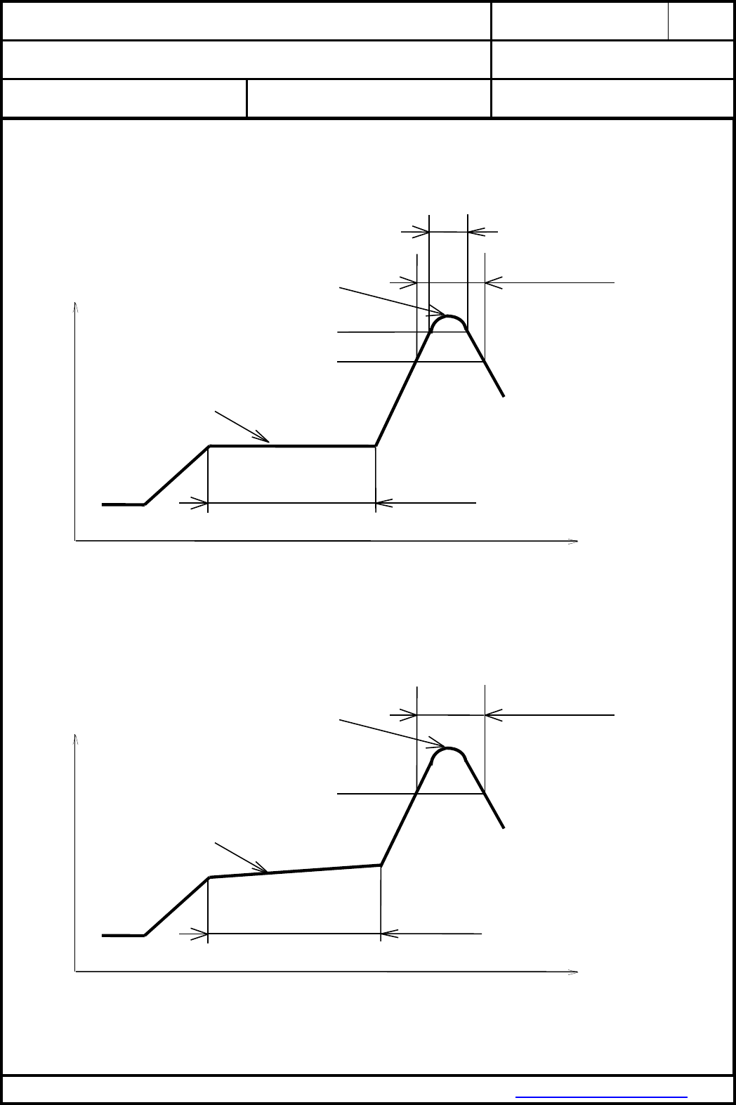
20. SOLDERING TEMPERATURE-TIME PROFILE (FOR REFLOW SOLDERING)
20.1. FOR LEAD SOLDER
Recommended temp. profile
for reflow soldering
Temp.[°C]
Time [s]
235°C max.
220 5°C
200°C
150 10°C
90 30s
10 1s
30 +20/-10s
20.2. FOR LEADFREE SOLDER
Our used temp. profile
for reflow soldering
Temp.[°C]
Time [s]
230°C -250°C max.
220°C
150°C – 190°C
90 30s
30 +20/-10s
Reflow permissible cycle: 2
Opposite side reflow is prohibited due to module weight.
CLASSIFICATION
PRODUCT SPECIFICATION
No.
DS-9320-2400-102
REV.
1.1
SUBJECT
WI-FI IEEE 802.11 BGN FULL EMBEDDED MODULE
PAGE
30 of 43
CUSTOMER’S CODE
PAN9320 / PAN9310
PANASONIC’S CODE
ENW49A01x3EF & ENW49A02x3EF
DATE
14.03.2016
PANASONIC INDUSTRIAL DEVICES EUROPE GMBH
www.pideu.panasonic.de
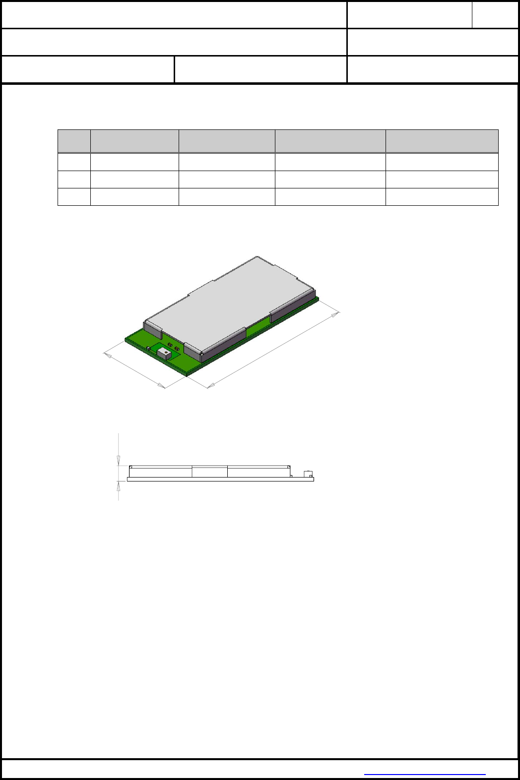
29
13,50
2,66
21. PAN9320 / PAN9310 MODULE DIMENSION
No.
Item
Dimension
Tolerance
Remark
1
Width
13.50
0.30
2
Length
29.00
0.30
3
Height
2.66
0.20
with case
CLASSIFICATION
PRODUCT SPECIFICATION
No.
DS-9320-2400-102
REV.
1.1
SUBJECT
WI-FI IEEE 802.11 BGN FULL EMBEDDED MODULE
PAGE
31 of 43
CUSTOMER’S CODE
PAN9320 / PAN9310
PANASONIC’S CODE
ENW49A01x3EF & ENW49A02x3EF
DATE
14.03.2016
PANASONIC INDUSTRIAL DEVICES EUROPE GMBH
www.pideu.panasonic.de
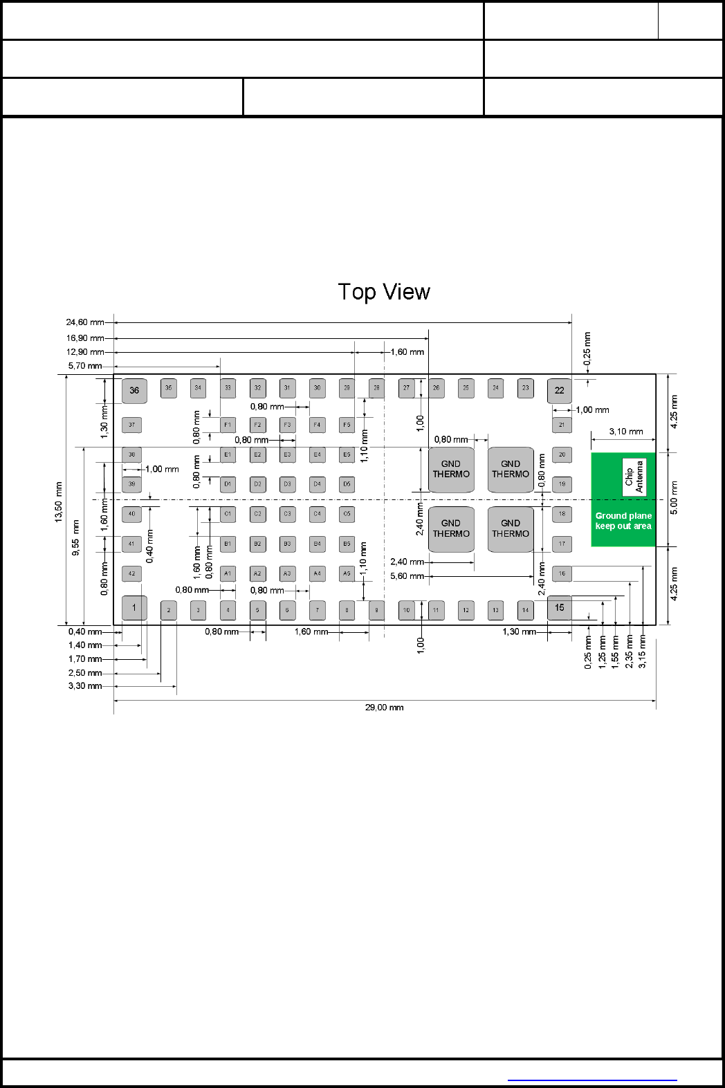
22. PAN9320 / PAN9310 FOOTPRINT OF THE MODULE
All dimensions are in millimeters.
The outer dimensions have a tolerance of 0.3mm.
Top view, Application PCB
CLASSIFICATION
PRODUCT SPECIFICATION
No.
DS-9320-2400-102
REV.
1.1
SUBJECT
WI-FI IEEE 802.11 BGN FULL EMBEDDED MODULE
PAGE
32 of 43
CUSTOMER’S CODE
PAN9320 / PAN9310
PANASONIC’S CODE
ENW49A01x3EF & ENW49A02x3EF
DATE
14.03.2016
PANASONIC INDUSTRIAL DEVICES EUROPE GMBH
www.pideu.panasonic.de
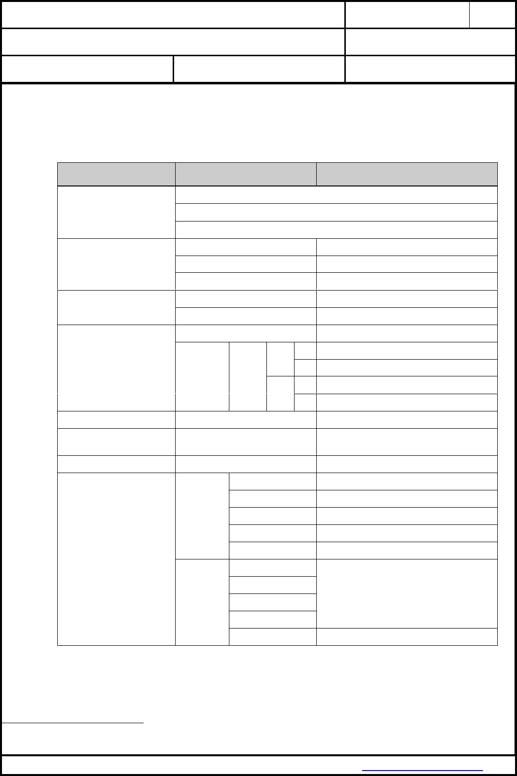
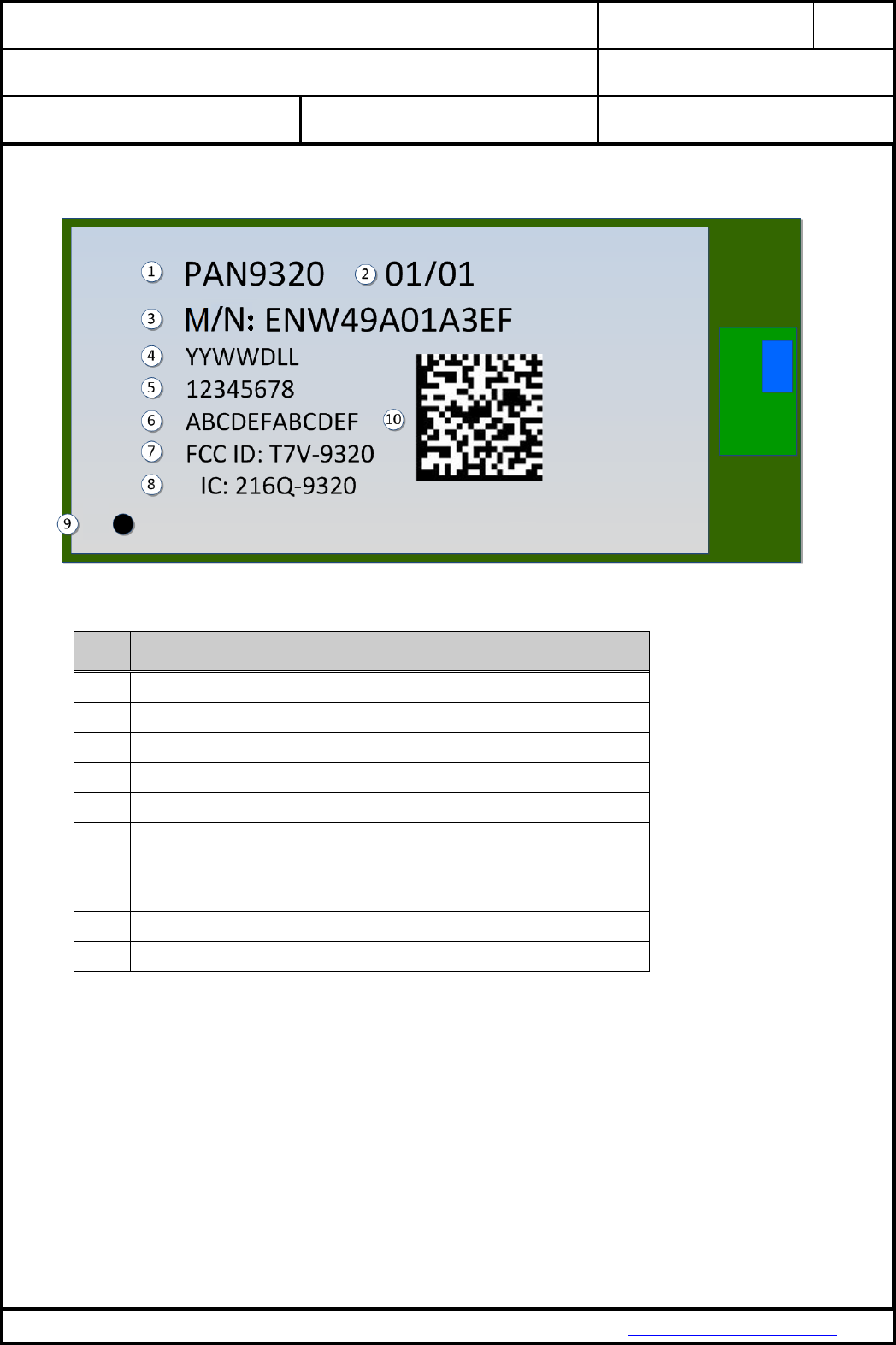
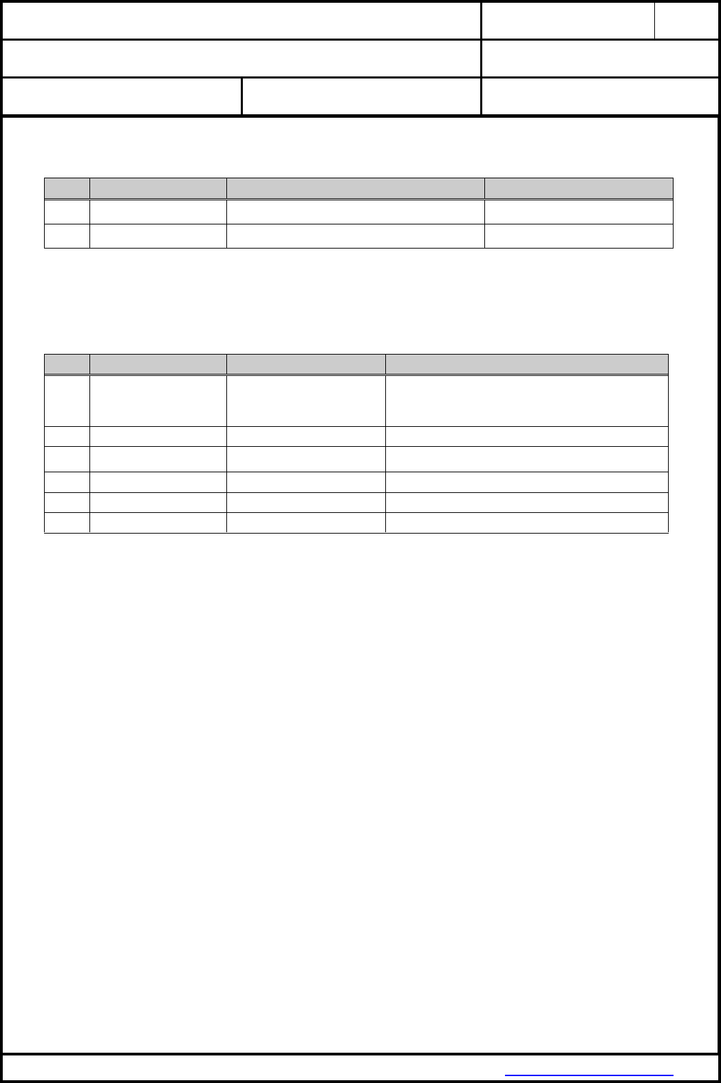
23. CASE MARKING (EXAMPLE FOR PAN9320 – FCC VERSION)
No.
Remark
1
PAN9320 or PAN9310 (Brand Name), see chapter 28. Ordering Information
2
Hardware / Software version
3
Model Name, see chapter 28. Ordering Information
4
Lot code: YearYear, WeekWeek, Day, LotLot
5
Serial Number (8 digits)
6
WLAN MAC address (12 digits)
7
FCC ID, refer to chapter 31.1 FCC for US
8
IC Canada, refer to chapter 31.2 Industry Canada Certification
9
Marking for Pin 1 (Circle 0,15 mm)
10
2D-Code, for internal usage only and can be change without any notice
CLASSIFICATION
PRODUCT SPECIFICATION
No.
DS-9320-2400-102
REV.
1.1
SUBJECT
WI-FI IEEE 802.11 BGN FULL EMBEDDED MODULE
PAGE
33 of 43
CUSTOMER’S CODE
PAN9320 / PAN9310
PANASONIC’S CODE
ENW49A01x3EF & ENW49A02x3EF
DATE
14.03.2016
PANASONIC INDUSTRIAL DEVICES EUROPE GMBH
www.pideu.panasonic.de
24. MECHANICAL REQUIREMENTS
No.
Item
Limit
Condition
1
Solderability
More than 75% of the soldering area shall be coated by
solder
Reflow soldering with recommendable
temperature profile
2
Resistance to soldering heat
It shall be satisfied electrical requirements and not be
mechanical damage
See chapter 20.2
25. RELIABILITY TESTS
The measurement should be done after being exposed to room temperature and humidity for 1 hour.
No.
Item
Limit
Condition
1
Vibration test
Electrical parameter should be in
specification
a) Freq.:10~50Hz,Amplitude:1.5mm
a) 20min. / cycle,1hrs. each of XYZ axis
b) Freq.:30~100Hz, 6G
b) 20min. / cycle,1hrs. each of XYZ axis
2
Shock test
the same as above
Dropped onto hard wood from height of 50cm for 3 times
3
Heat cycle test
the same as above
-40°C for 30min. and +85°C for 30min.;
each temperature 300 cycles
4
Moisture test
the same as above
+60°C, 90% RH, 300h
5
Low temp. test
the same as above
-40°C, 300h
6
High temp. test
the same as above
+85°C, 300h
26. CAUTIONS
Failure to follow the guidelines set forth in this document may result in degrading of the product’s functions
and damage to the product.
26.1. DESIGN NOTES
(1) Follow the conditions written in this specification, especially the control signals of this
module.
(2) The supply voltage must be free of AC ripple voltage (for example from a battery or a low
noise regulator output). For noisy supply voltages, provide a decoupling circuit (for
example a ferrite in series connection and a bypass capacitor to ground of at least 47uF
directly at the module).
(3) This product should not be mechanically stressed when installed.
(4) Keep this product away from heat. Heat is the major cause of decreasing the life of these
products.
(5) Avoid assembly and use of the target equipment in conditions where the products'
temperature may exceed the maximum tolerance.
(6) The supply voltage should not be exceedingly high or reversed. It should not carry noise
and/or spikes.
(7) Keep this product away from other high frequency circuits.

CLASSIFICATION
PRODUCT SPECIFICATION
No.
DS-9320-2400-102
REV.
1.1
SUBJECT
WI-FI IEEE 802.11 BGN FULL EMBEDDED MODULE
PAGE
34 of 43
CUSTOMER’S CODE
PAN9320 / PAN9310
PANASONIC’S CODE
ENW49A01x3EF & ENW49A02x3EF
DATE
14.03.2016
PANASONIC INDUSTRIAL DEVICES EUROPE GMBH
www.pideu.panasonic.de
26.2. INSTALLATION NOTES
(1) Reflow soldering is possible twice based on the conditions in chapter 15.
Set up the temperature at the soldering portion of this product according to this reflow
profile.
(2) Carefully position the products so that their heat will not burn into printed circuit boards or
affect the other components that are susceptible to heat.
(3) Carefully locate these products so that their temperatures will not increase due to the
effects of heat generated by neighboring components.
(4) If a vinyl-covered wire comes into contact with the products, then the cover will melt and
generate toxic gas, damaging the insulation. Never allow contact between the cover and
these products to occur.
(5) This product should not be mechanically stressed or vibrated when reflowed.
(6) To repair the board by hand soldering, follow the conditions set forth in this chapter.
(7) Do not wash this product.
(8) Refer to the recommended pattern when designing a board.
(9) Pressing on parts of the metal cover or fastening objects to the metal will cause damage to
the unit.
(10) For more details on LGA (Land Grid Array) soldering processes refer to the application
note [7].
26.3. USAGE CONDITIONS NOTES
(1) Take measures to protect the unit against static electricity.
If pulses or other transient loads (a large load applied in a short time) are applied to the
products, check and evaluate their operation befor assembly on the final products.
(2) Do not use dropped products.
(3) Do not touch, damage or soil the pins.
(4) Follow the recommended condition ratings about the power supply applied to this product.
(5) Electrode peeling strength: Do not add pressure of more than 4.9N when soldered on PCB.
(6) Pressing on parts of the metal cover or fastening objects to the metal cover will cause
damage.
(7) These products are intended for general purpose and standard use in general electronic
equipment, such as home appliances, office equipment, information and communication
equipment.
26.4. STORAGE NOTES
(1) The module should not be stressed mechanically during storage.
(2) Do not store these products in the following conditions or the performance characteristics
of the product, such as RF performance will be adversely affected:
Storage in salty air or in an environment with a high concentration of corrosive gas, such as
Cl2, H2S, NH3, SO2, or NOX
Storage in direct sunlight
Storage in an environment where the temperature may be outside the range of 5°C to 35°C
range, or where the humidity may be outside the 45 to 85% range.
Storage of the products for more than one year after the date of delivery Storage period:
Please check the adhesive strength of the embossed tape and soldering after 6 months of
storage.
(3) Keep this product away from water, poisonous gas and corrosive gas.
(4) This product should not be stressed or shocked when transported.
(5) Follow the specification when stacking packed crates (max. 10).

CLASSIFICATION
PRODUCT SPECIFICATION
No.
DS-9320-2400-102
REV.
1.1
SUBJECT
WI-FI IEEE 802.11 BGN FULL EMBEDDED MODULE
PAGE
35 of 43
CUSTOMER’S CODE
PAN9320 / PAN9310
PANASONIC’S CODE
ENW49A01x3EF & ENW49A02x3EF
DATE
14.03.2016
PANASONIC INDUSTRIAL DEVICES EUROPE GMBH
www.pideu.panasonic.de
26.5. SAFETY CAUTIONS
These specifications are intended to preserve the quality assurance of products and individual
components.
Before use, check and evaluate the operation when mounted on your products. Abide by these
specifications, without deviation when using the products. These products may short-circuit. If electrical
shocks, smoke, fire, and/or accidents involving human life are anticipated when a short circuit occurs,
then provide the following failsafe functions, as a minimum.
(1) Ensure the safety of the whole system by installing a protection circuit and a protection
device.
(2) Ensure the safety of the whole system by installing a redundant circuit or another system to
prevent a single fault causing an unsafe status.
26.6. OTHER CAUTIONS
(1) This specification sheet is copyrighted. Do not disclose it to a third party.
(2) Do not use the products for other purposes than those listed.
(3) Be sure to provide an appropriate fail-safe function on your product to prevent an additional
damage that may be caused by the abnormal function or the failure of the product.
(4) This product has been manufactured without any ozone chemical controlled under the
Montreal Protocol.
(5) These products are not intended for other uses, other than under the special conditions
shown below. Before using these products under such special conditions, check their
performance and reliability under the said special conditions carefully to determine whether
or not they can be used in such a manner.
In liquid, such as water, salt water, oil, alkali, or organic solvent, or in places where liquid
may splash.
In direct sunlight, outdoors, or in a dusty environment
In an environment where condensation occurs.
In an environment with a high concentration of harmful gas (e.g. salty air, HCl, Cl2, SO2,
H2S, NH3, and NOX)
(6) If an abnormal voltage is applied due to a problem occurring in other components or
circuits, replace these products with new products because they may not be able to provide
normal performance even if their electronic characteristics and appearances appear
satisfactory.
(7) When you have any question or uncertainty, contact Panasonic.
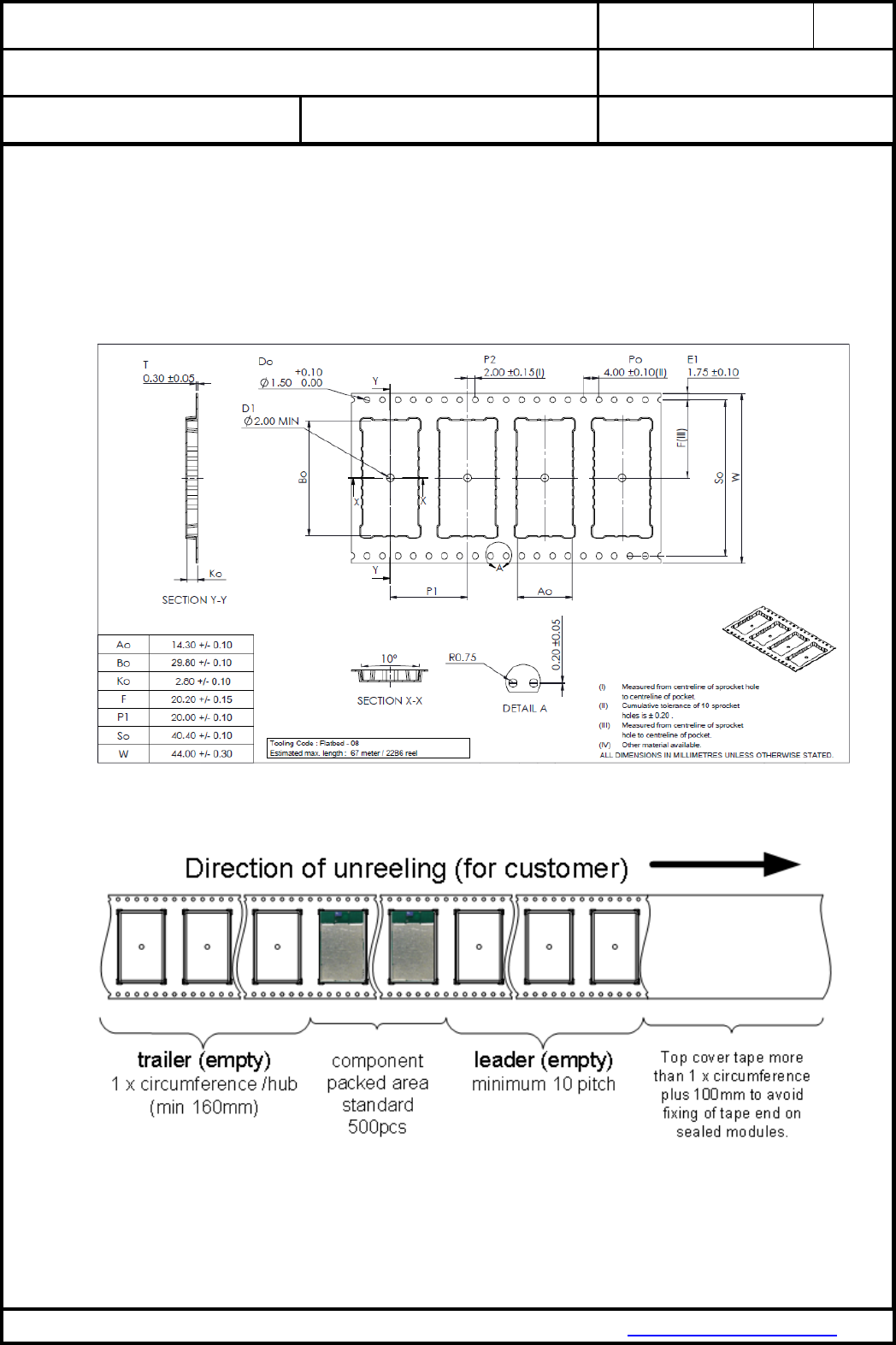
CLASSIFICATION
PRODUCT SPECIFICATION
No.
DS-9320-2400-102
REV.
1.1
SUBJECT
WI-FI IEEE 802.11 BGN FULL EMBEDDED MODULE
PAGE
36 of 43
CUSTOMER’S CODE
PAN9320 / PAN9310
PANASONIC’S CODE
ENW49A01x3EF & ENW49A02x3EF
DATE
14.03.2016
PANASONIC INDUSTRIAL DEVICES EUROPE GMBH
www.pideu.panasonic.de
27. PACKAGING
Mass production status product -- as indicated in Chapter 3 -- will be delivered in the package described
below.
27.1. TAPE DIMENSION
27.2. PACKING IN TAPE
Empty spaces in component packed area shall be less than two per reel and those spaces shall not be
consecutive.
Top cover tape shall not be found on reel holes and shall not stick out from reel.
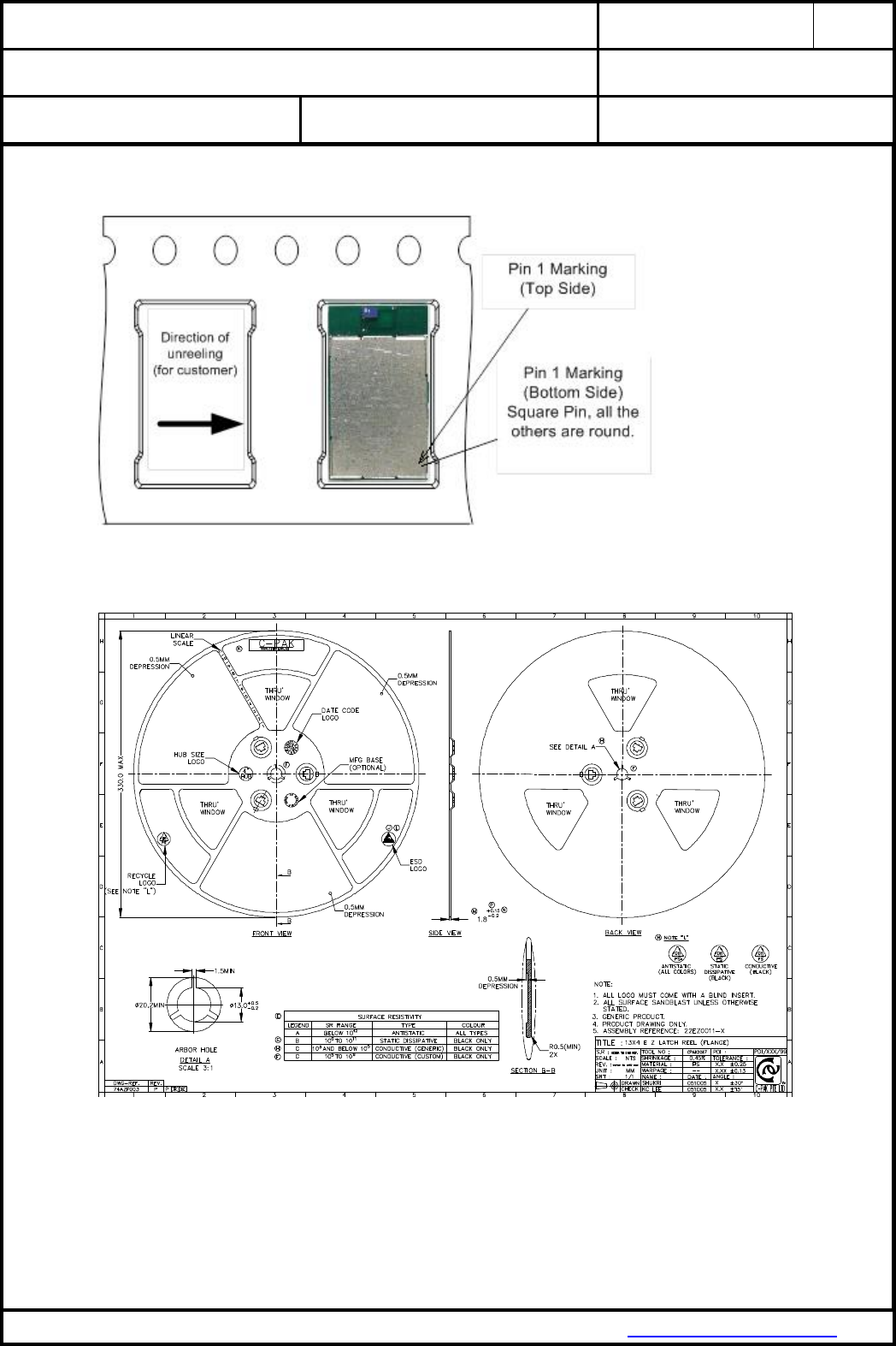
CLASSIFICATION
PRODUCT SPECIFICATION
No.
DS-9320-2400-102
REV.
1.1
SUBJECT
WI-FI IEEE 802.11 BGN FULL EMBEDDED MODULE
PAGE
37 of 43
CUSTOMER’S CODE
PAN9320 / PAN9310
PANASONIC’S CODE
ENW49A01x3EF & ENW49A02x3EF
DATE
14.03.2016
PANASONIC INDUSTRIAL DEVICES EUROPE GMBH
www.pideu.panasonic.de
27.3. COMPONENT DIRECTION
27.4. REEL DIMENSION
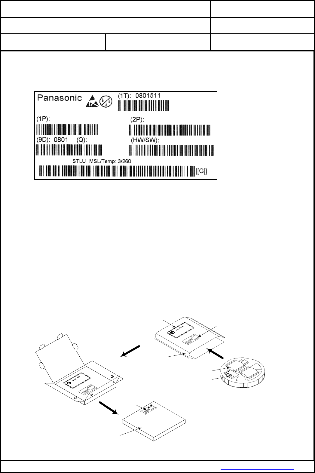
CLASSIFICATION
PRODUCT SPECIFICATION
No.
DS-9320-2400-102
REV.
1.1
SUBJECT
WI-FI IEEE 802.11 BGN FULL EMBEDDED MODULE
PAGE
38 of 43
CUSTOMER’S CODE
PAN9320 / PAN9310
PANASONIC’S CODE
ENW49A01x3EF & ENW49A02x3EF
DATE
14.03.2016
PANASONIC INDUSTRIAL DEVICES EUROPE GMBH
www.pideu.panasonic.de
27.5. LABEL FOR PACKAGE
The picture shows an example from similar product.
(1T) Lot code [YYWWDLL-AAA] Example from above:
YY year printed 08
WW normal calendar week printed 01
D day printed 5 (Friday)
L line identifier, if more as one printed 1
L lot identifier per day printed 1
AAA number of the reel (example 001, 002,…, 999) printed 001
(1P) Customer Order Code, if any, otherwise company name will be printed
(2P) Panasonic Order Code: ENW49A01A3EF (see chapter 28 Ordering Information)
(3P) Model type (see chapter 28. Ordering Information)
(9D) Date code as [YYWW]
(Q) Quantity [XXXX], variable max. 500
(HW/SW) Hardware/Software Release
27.6. TOTAL PACKAGE
barcode
label
moisture-sensitive print
(already exist on barrier bag) barcode
label
desiccant 1) 2)
moisture indicator
barrier bag
sealed
inner carton box
size 340 x 340 x 41 mm³
1) quantity of desiccant according
to calculation
2) optional: desiccant placed into
the corner of the barrier bag
(3P): PAN9320
RoHS
-AAA
ENW49A01A3EF
Company
500
xy/ab
Country of Origin: Slovakia
CLASSIFICATION
PRODUCT SPECIFICATION
No.
DS-9320-2400-102
REV.
1.1
SUBJECT
WI-FI IEEE 802.11 BGN FULL EMBEDDED MODULE
PAGE
39 of 43
CUSTOMER’S CODE
PAN9320 / PAN9310
PANASONIC’S CODE
ENW49A01x3EF & ENW49A02x3EF
DATE
14.03.2016
PANASONIC INDUSTRIAL DEVICES EUROPE GMBH
www.pideu.panasonic.de
28. ORDERING INFORMATION
Model Name
Brand Name
Regulatory
Supported Channel
Description
MOQ (4)
ENW49A01A3EF
PAN9320
FCC / IC (1)
for US and
for Canada
Channel 1 ~ 11
2412 ~ 2462 MHz
WLAN IEEE 802.11 b/g/n 2.4GHz Full Embedded
Module with ceramic chip-antenna
500
ENW49A01C3EF
PAN9310 (3)
WLAN IEEE 802.11 b/g/n 2.4GHz Full Embedded
Module with RF bottom pad
500
ENW49A02A3EF
PAN9320
ETSI (2)
for EU
and other
Channel 1 ~ 13
2412 ~ 2472 MHz
WLAN IEEE 802.11 b/g/n 2.4GHz Full Embedded
Module with ceramic chip-antenna
500
ENW49A02C3EF
PAN9310 (3)
WLAN IEEE 802.11 b/g/n 2.4GHz Full Embedded
Module with RF bottom pad
500
The PAN9320 / PAN9310 will be delivered with a pre-installed firmware, see PAN9320 Communication
Specification [3] and PAN9320 Design Guide [1].
Notes:
(1) The model with Regulatory Domain FCC / IC (M/N: ENW49A01A3EF) are only intended to be used in the countries of US
and Canada because only the channels 1 ~ 11 (2412 ~ 2462 MHz) are supported in the 2.4GHz ISM band. It is not
possible to change the pre-stored Region Code in order to change the Regulatory Domain. Thus the module labeling
contains the FCC Grant ID.
(2) The model with Regulatory Domain ETSI (M/N: ENW49A02A3EF) are mainly intended to be used in European countries
because the channels 1 ~ 13 (2412 ~ 2472 MHz) are supported. The Region Code is pre-configured (using Default Config
Content in Flash memory) to Regulatory Domain ETSI and thus the module labeling doesn’t contain the FCC ID. At the
end the customer is able to change applied Region Code by his own Customer Config Content to be stored during
customer OEMs product production in the flash memory. It means the FCC Regulatory Domain can be configured as well,
but the customer has to certify the end product by itself.
(3) The models with brand name PAN9310 don’t have the Chip antenna on module. The Grant ID’s marked on module
labelling are referenced and are only valid in case of customer is applying the same antenna (listed in 31.1.5) including
the reference design described in the Design Guide [1]. In this case the customer can refer to the pre-qualified module’s
modular approval which needs finally to be approved by the certification body of regulatory authority.
(4) Abbreviation for Minimum Order Quantity (MOQ). The standard MOQ for mass production is 500 pieces, fewer only on
customer demand. Samples for evaluation can be delivered at any quantity via the distribution channels.
29. SOFTWARE VERSIONS
The version numbers of the embedded MCU firmware and WLAN SoC firmware can be read out by UART
commands which are specified in the PAN9320 Communication Specification [3] and listed below:
No.
Item
UART Command
Response example
1
MCU firmware version
get system firmware
get system firmware 0 1.9.0.1
2
WLAN SoC firmware version
get system wifi_ver
get system wifi_ver 0 "w8782-B0, RF878X, FP69, 14.69.12.p40"
30. ROHS DECLARATION
Declaration of environmental compatibility for supplied products:
Hereby we declare to our best present knowledge based on declaration of our suppliers that this product
does not contain the following substances which are banned by Directive 2002/95/EC (RoHS) or contains a
maximum concentration of 0.1% by weight in homogeneous materials for
Lead and lead compounds
Mercury and mercury compounds
Chromium (VI)
PBB (polybrominated biphenyl) category
PBDE (polybrominated biphenyl ether) category
And a maximum concentration of 0.01% by weight in homogeneous materials for
Cadmium and cadmium compounds
CLASSIFICATION
PRODUCT SPECIFICATION
No.
DS-9320-2400-102
REV.
1.1
SUBJECT
WI-FI IEEE 802.11 BGN FULL EMBEDDED MODULE
PAGE
40 of 43
CUSTOMER’S CODE
PAN9320 / PAN9310
PANASONIC’S CODE
ENW49A01x3EF & ENW49A02x3EF
DATE
14.03.2016
PANASONIC INDUSTRIAL DEVICES EUROPE GMBH
www.pideu.panasonic.de
31. REGULATORY INFORMATION
31.1. FCC FOR US
31.1.1. FCC Notice
The PAN9320, including the ceramic antenna (ENW49A01A3EF) and the PAN9310 SMD type
(ENW49A01C3EF), including with the antennas, which are listed in 31.1.5, complies with Part 15 of
the FCC Rules.
The device meets the requirements for modular transmitter approval as detailed in FCC public
Notice DA00-1407.transmitter Operation is subject to the following two conditions:
(1) This device may not cause harmful interference, and
(2) This device must accept any interference received, including interference that may cause
undesired operation.
The FCC identifier for ENW49A01x3EF
(
16
) is FCC ID: T7V-9320
31.1.2. Caution
The FCC requires the user to be notified that any changes or modifications made to this device that
are not expressly approved by Panasonic Industrial Devices Europe GmbH may void the user's
authority to operate the equipment.
This equipment has been tested and found to comply with the limits for a Class B digital device,
pursuant to Part 15 of the FCC Rules. These limits are designed to provide reasonable protection
against harmful interference in a residential installation. This equipment generates uses and can
radiate radio frequency energy and, if not installed and used in accordance with the instructions,
may cause harmful interference to radio communications. However, there is no guarantee that
interference will not occur in a particular installation. If this equipment does cause harmful
interference to radio or television reception, which can be determined by turning the equipment off
and on, the user is encouraged to try to correct the interference by one or more of the following
measures:
Reorient or relocate the receiving antenna.
Increase the separation between the equipment and receiver.
Connect the equipment into an outlet on a circuit different from that to which the receiver is
connected.
Consult the dealer or an experienced radio/TV technician for help
31.1.3. Label Requirements
The Original Equipment Manufacturer (OEM) must ensure that FCC labelling requirements are
met. This includes a clearly visible label (laser marking) on the outside of the OEM enclosure
specifying the appropriate Panasonic FCC identifier for this product as well as the FCC Notice
above. The FCC identifier is FCC ID: T7V-9320 for model ENW49A01x3EF
(16).
This FCC identifier is valid for PAN9320, for details see the Chapter 28 Ordering Information. In
any case the end product must be labelled exterior with
"Contains FCC ID: T7V-9320"
31.1.4. Antenna Warning
The related model number for the device is ENW49A01C3EF (PAN9310 with SMD pad). For
details, see the Chapter 28 Ordering Information. The device is tested with a standard SMA
connector and with the antenna listed below. When integrated in the OEMs product, these fixed
antennas require installation preventing end-users from replacing them with non-approved
antennas. Any antenna not in the following table must be tested to comply with FCC Section
15.203 for unique antenna connectors and Section 15.247 for emissions. The FCC identifier for the
device with the antenna listed in chapter 31.1.5 is the same (FCC ID: T7V-9320).
16
x = „A“ for PAN9320 and x = „C“ for PAN9310 (e.g. ENW49A01A3EF x = “A”)

CLASSIFICATION
PRODUCT SPECIFICATION
No.
DS-9320-2400-102
REV.
1.1
SUBJECT
WI-FI IEEE 802.11 BGN FULL EMBEDDED MODULE
PAGE
41 of 43
CUSTOMER’S CODE
PAN9320 / PAN9310
PANASONIC’S CODE
ENW49A01x3EF & ENW49A02x3EF
DATE
14.03.2016
PANASONIC INDUSTRIAL DEVICES EUROPE GMBH
www.pideu.panasonic.de
31.1.5. Approved Antenna List
Note: We are able to qualify your antenna and will add to this list as that process is completed.
31.1.6. RF Exposure
To comply with FCC RF Exposure requirements, the Original Equipment Manufacturer (OEM) must
ensure that the approved antenna in the previous table must be installed.
The preceding statement must be included as a CAUTION statement in manuals for products
operating with the approved antennas in the previous table to alert users on FCC RF Exposure
compliance.
Any notification to the end user of installation or removal instructions about the integrated radio
module is not allowed.
The RF exposure requirements of PAN9320 with mounted ceramic chip antenna (FCC ID: T7V-
9320 for model ENW49A01A3EF) are fulfilled for mobile configuration. The installation of the
module is restricted to mobile host devices. Nevertheless, the PAN9320 shall be used in such a
manner that the potential for human contact during normal operation is minimized.
End users may not be provided with the module installation instructions. OEM integrators and end
users must be provided with transmitter operating conditions for satisfying RF exposure compliance.
31.2. INDUSTRY CANADA CERTIFICATION
PAN9320 and versions are licensed to meet the regulatory requirements of Industry Canada (IC),
License for M/N: ENW49A01x3EF
(16): IC: 216Q-9320
License for M/N: ENW49A02x3EF
(16): IC: 216Q-9320
Manufacturers of mobile, fixed or portable devices incorporating this module are advised to clarify
any regulatory questions and ensure compliance for SAR and/or RF exposure limits. Users can
obtain Canadian information on RF exposure and compliance from www.ic.gc.ca.
This device has been designed to operate with the antennas listed in 31.1.5 above, having a
maximum gain of +0.8dBi. Antennas not included in this list or having a gain greater than +0.8dBi
are strictly prohibited for use with this device. The required antenna impedance is 50 ohms. The
antenna used for this transmitter must not be co-located or operating in conjunction with any other
antenna or transmitter.
Due to the model size the IC identifier is displayed in the installation instruction only and can’t be
displayed on the modules label due to the limited size.
31.2.1. IC Notice
The device PAN9320 and versions, for details refer to Chapter 28. Ordering Information, including
the antennas, which are listed in 31.1.5, complies with Canada RSS-GEN Rules. The device meets
the requirements for modular transmitter approval as detailed in RSS-GEN.
Operation is subject to the following two conditions:
(1) This device may not cause harmful interference, and
(2) This device must accept any interference received, including interference that may cause
undesired operation.
Item
Part Number
Manufacturer
Frequency Band
Type
Gain (dBi)
1
ANT2012LL13R2400A
Yageo
2.4GHz
Chip-Antenna
+0.8

CLASSIFICATION
PRODUCT SPECIFICATION
No.
DS-9320-2400-102
REV.
1.1
SUBJECT
WI-FI IEEE 802.11 BGN FULL EMBEDDED MODULE
PAGE
42 of 43
CUSTOMER’S CODE
PAN9320 / PAN9310
PANASONIC’S CODE
ENW49A01x3EF & ENW49A02x3EF
DATE
14.03.2016
PANASONIC INDUSTRIAL DEVICES EUROPE GMBH
www.pideu.panasonic.de
31.2.2. Labeling Requirements
The Original Equipment Manufacturer (OEM) must ensure that IC labelling requirements are met.
This includes a clearly visible label on the outside of the OEM enclosure specifying the appropriate
Panasonic IC identifier for this product as well as the IC Notice above.
The IC identifiers are: IC: 216Q-9320 (for M/N: ENW49A01x3EF
(16))
IC: 216Q-9320 (for M/N: ENW49A02x3EF
(16))
This IC identifier is valid for all PAN9320, for details, see the Chapter 28 Ordering Information. In
any case the end product must be labelled exterior with:
"Contains IC: 216Q-9320”
Les fabricants d’équipements (OEM) doivent s’assurer que les obligations d’étiquetage du produit
final sont remplies. Ces obligations incluent une étiquette clairement visible à l’extérieur de
l’emballage externe, comportant l’identifiant IC du module Panasonic inclus, ainsi que la notification
ci-dessus.
Les identifiants IC sont: IC: 216Q-9320 (pour M/N: ENW49A01x3EF
(16))
IC: 216Q-9320 (pour M/N: ENW49A02x3EF
(16))
Ces identifiants sont valides pour tous les PAN9320 (28 Ordering Information). Dans tous les cas
les produits finaux doivent indiquer sur leur emballage externe une des mentions suivantes:
"Contient IC: 216Q-9320”
31.3. EUROPEAN R&TTE DECLARATION OF CONFORMITY
All modules described in this data sheet comply to the standards according R&TTE article:
3.1a Safety/Health: EN60950-1:2006+A11:2009+A1:2010+A12:2011+AC:2011+A2:2013
EN62311:2008
3.1b EMC: EN 301 489-1 V1.8.1:2008-04
EN 301 489-17 V2.2.1:2012-09
3.2 Radio: EN 300 328 V1.8.1:2012-06
As a result of the conformity assessment procedure described in Annex III of the Directive
1999/5/EC, the end-customer equipment should be labelled as follows:
The end-customer has to assure that the device has a distance of more than 20cm from the human
body under all circumstances.
The end-customer equipment must meet the actual Safety/Health requirements according R&TTE.
PAN9320 and their model versions in the specified reference design can be used in the following
countries: Austria, Belgium, Cyprus, Czech Republic, Denmark, Estonia, Finland, France, Germany,
Greece, Hungary, Ireland, Italy, Latvia, Lithuania, Luxembourg, Malta, Poland, Portugal, Slovakia,
Slovenia, Spain, Sweden, Netherland, the United Kingdom, Switzerland, and Norway.

CLASSIFICATION
PRODUCT SPECIFICATION
No.
DS-9320-2400-102
REV.
1.1
SUBJECT
WI-FI IEEE 802.11 BGN FULL EMBEDDED MODULE
PAGE
43 of 43
CUSTOMER’S CODE
PAN9320 / PAN9310
PANASONIC’S CODE
ENW49A01x3EF & ENW49A02x3EF
DATE
14.03.2016
PANASONIC INDUSTRIAL DEVICES EUROPE GMBH
www.pideu.panasonic.de
32. GENERAL INFORMATION
© Panasonic Industrial Devices Europe GmbH 2015.
All rights reserved.
This product description does not lodge the claim to be complete and free of mistakes.
Please contact the related product manager in every case.
If ES samples are delivered to the customer, these samples have the status Engineering Samples. This
means, the design of this product is not yet concluded. Engineering Samples may be partially or fully
functional, and there may be differences to be published Data Sheet.
Engineering Samples are not qualified and are not to be used for reliability testing or series production.
Disclaimer:
Customer acknowledges that samples may deviate from the Data Sheet and may bear defects due to
their status of development and the lack of qualification mentioned above.
Panasonic rejects any liability or product warranty for Engineering Samples. In particular, Panasonic
disclaims liability for damages caused by:
The use of the Engineering Sample other than for Evaluation Purposes, particularly the
installation or integration in another product to be sold by Customer,
Deviation or lapse in function of Engineering Sample,
Improper use of Engineering Samples.
Panasonic Industrial Devices Europe GmbH disclaimes any liability for consequential and incidental
damages. In case of any questions, please contact your local sales partner or the related product
manager.
33. LIFE SUPPORT POLICY
This Panasonic Industrial Devices Europe GmbH product is not designed for use in life support
appliances, devices, or systems where malfunction can reasonably be expected to result in a significant
personal injury to the user, or as a critical component in any life support device or system whose failure to
perform can be reasonably expected to cause the failure of the life support device or system, or to affect
its safety or effectiveness. Customers using or selling these products for use in such applications do so at
their own risk and agree to fully indemnify Panasonic Industrial Devices Europe GmbH for any damages
resulting.