Panasonic Devices Europe EM250A ZigBee module PAN4570 / ETRX2 User Manual 1
Panasonic Industrial Devices Europe GmbH ZigBee module PAN4570 / ETRX2 1
UserManual.wiki
>
Panasonic Devices Europe
>
EM250A User Manual
>
user manual
Contents
1.
user manual
2.
user manual 2
user manual
Navigation menu
Upload a User Manual
Namespaces
Wiki Guide
HTML
PDF
Info
Views
User Manual
Discussion / Help
Navigation
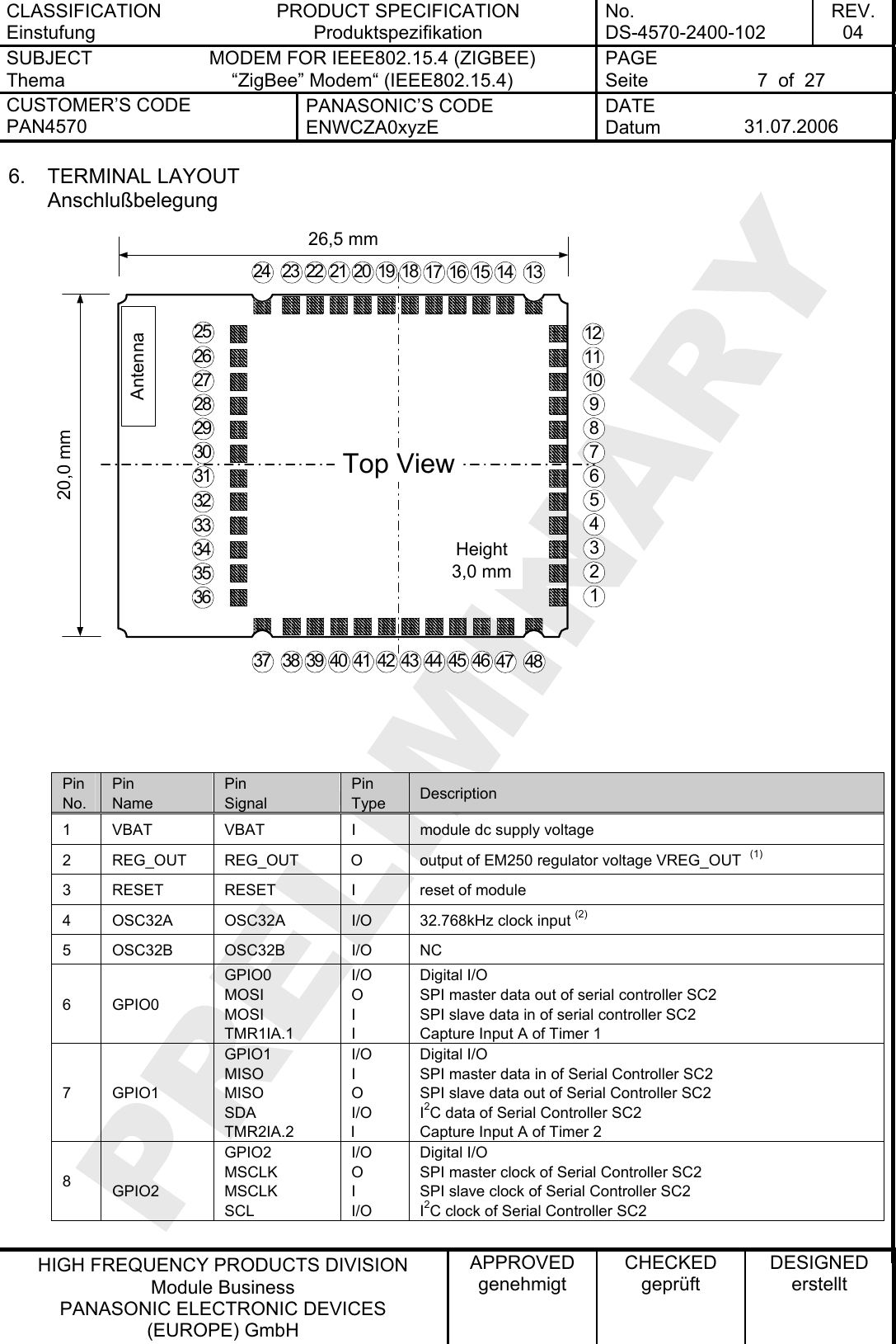
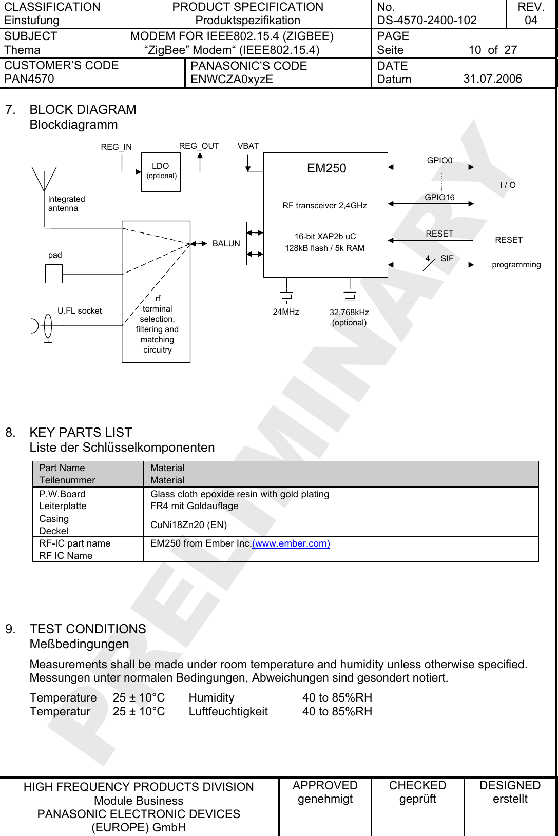
![CLASSIFICATION Einstufung PRODUCT SPECIFICATION Produktspezifikation No. DS-4570-2400-102 REV. 04 SUBJECT Thema MODEM FOR IEEE802.15.4 (ZIGBEE) “ZigBee” Modem“ (IEEE802.15.4) PAGE Seite 4 of 27 CUSTOMER’S CODE PAN4570 PANASONIC’S CODE ENWCZA0xyzE DATE Datum 31.07.2006 HIGH FREQUENCY PRODUCTS DIVISION Module Business PANASONIC ELECTRONIC DEVICES (EUROPE) GmbH APPROVED genehmigt CHECKED geprüft DESIGNED erstellt 1. KEY FEATURES Schlüsseleigenschaften • short range 2,4GHz ISM band IEEE802.15.4 [1] compliant transceiver • Complete system based on the ZigBeeTM compliant platform EM250 that combines the transceiver with a powerful, efficient industry proven 16-bit microprocessor with comprehensive hardware supported network-level debugging features • designed specifically for use with EmberZNet, Embers ZigBee compliant embedded mesh networking • powerful 16-bit microprocessor • 128k flash ROM and 5k of SRAM memory • high Rx sensitivity of –97dBm at 1% Packet Error Rate • 3dBm Tx maximum output power with power control over 20dB range • Small size 20mm x 26,5mm x 3,0mm • single port antenna terminal (pcb pad, U.FL socket or chip antenna versions available) • Integrated ADC module with 12-bit resolution • two 16-bit general purpose timers; one 16-bit sleep timer • 17 GPIO pins with alternate functions • two sleep modes for increased battery life • low voltage detect/reset • complies with ETSI EN300 328 and FCC part 15 2. APPLICATIONS FOR THE MODULE Anwendungen für das Modul • ZigBeeTM FFD (full functional) and RFD (reduced functional) devices working in star and mesh networks • Wireless sensor and actuator networks • Remote control and wire replacement in industrial systems • Building automation and control • Inventory and logistics management • HID (Human Interface Devices) • Toys • Home gateways](https://usermanual.wiki/Panasonic-Devices-Europe/EM250A.user-manual/User-Guide-690108-Page-4.png)
![CLASSIFICATION Einstufung PRODUCT SPECIFICATION Produktspezifikation No. DS-4570-2400-102 REV. 04 SUBJECT Thema MODEM FOR IEEE802.15.4 (ZIGBEE) “ZigBee” Modem“ (IEEE802.15.4) PAGE Seite 5 of 27 CUSTOMER’S CODE PAN4570 PANASONIC’S CODE ENWCZA0xyzE DATE Datum 31.07.2006 HIGH FREQUENCY PRODUCTS DIVISION Module Business PANASONIC ELECTRONIC DEVICES (EUROPE) GmbH APPROVED genehmigt CHECKED geprüft DESIGNED erstellt 3. DESCRIPTION OF THE MODULE Beschreibung des Moduls PAN4570 contains the single chip EM250 [2] from Ember Inc., a 24MHz reference crystal and RF frontend circuitry optimized for best RF performance. As single ended RF output the module is available with integrated antenna or 50ohms or U.FL male socket [3] or 50 ohms pad terminal on the bottom of the module. Two additional hardware options are available on request: 3.1. ON BOARD DC REGULATOR Although the EM250 already contains a dc regulator internally, the module can be requested with an extra onboard linear low dropout (LDO) regulator. Some applications could benefit from this additional regulator because as of for example: (1) Further extension of the input voltage range or (2) Extented battery life by replacing the regulator within EM250 by a special ultra low quiescent current regulator or (3) allowing for operation on very noisy power supplies 3.2. ON BOARD REFERENCE CRYSTAL A second option that is available is an on board 32,768kHz crystal reference. This option is provided for applications that require a precision reference clock. Where a precision 32,768kHz reference is already available on the applicationboard, it could be fed to pin 4 instead and this option is not needed. Please contact the manufacturer if one of the options could be useful for your product design. PAN4570 is used for ZigBeeTM (www.zigbee.org) applications working with EmberZNetTM of Ember Inc. (www.ember.com). EmberZNetTM is a fully ZigBeeTM compliant networking stack. For code development Insight DesktopTM, a comprehensive integrated development environment (IDE) and C-language compiler toolchain from Ember Inc. is required. Insight DesktopTM is part of Ember development kits and can currently be purchased together with programming adaptors as EM250 jumpstart kit at a price of USD 2500,- directly from Ember Inc. (www.ember.com). When using ZigBeeTM technology for a product the following additional costs have to be taken into account: 1. Membership of the ZigBeeTM alliance, as least as adopter member for US$ 3500,-. 2. The cost of a ZigBeeTM product certification at a testhouse (TÜV Rheinland) ranges from approximately US$ 4000,- to US$ 10000,-, depending on the implemented software. 3. Products qualifying for ZigBeeTM certification at the ZigBeeTM alliance need a logo](https://usermanual.wiki/Panasonic-Devices-Europe/EM250A.user-manual/User-Guide-690108-Page-5.png)
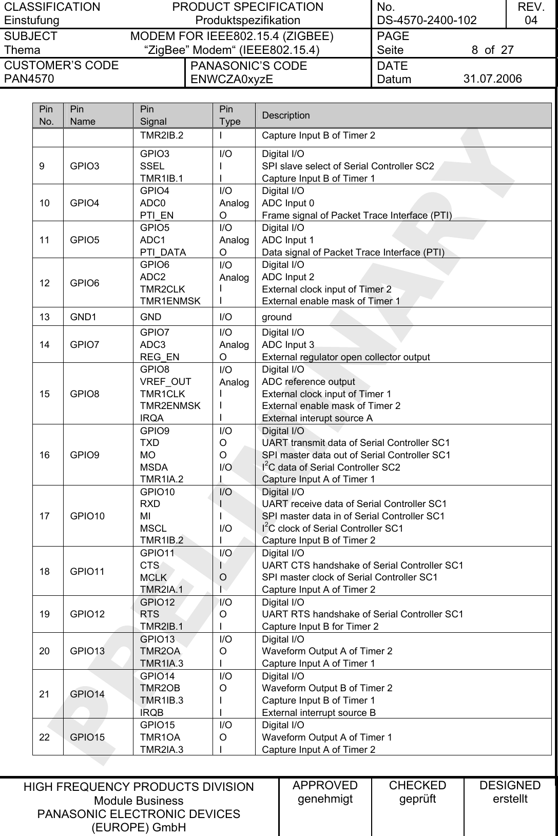
![CLASSIFICATION Einstufung PRODUCT SPECIFICATION Produktspezifikation No. DS-4570-2400-102 REV. 04 SUBJECT Thema MODEM FOR IEEE802.15.4 (ZIGBEE) “ZigBee” Modem“ (IEEE802.15.4) PAGE Seite 11 of 27 CUSTOMER’S CODE PAN4570 PANASONIC’S CODE ENWCZA0xyzE DATE Datum 31.07.2006 HIGH FREQUENCY PRODUCTS DIVISION Module Business PANASONIC ELECTRONIC DEVICES (EUROPE) GmbH APPROVED genehmigt CHECKED geprüft DESIGNED erstellt 10. ABSOLUTE MAXIMUM RATINGS Absolute Grenzwerte The maximum ratings may not be exceeded under any circumstances, not even momentarily and individually, as permanent damage to the module will result. No. Item Punkt Symbol Zeichen Absolute Maximum Ratings Absolute Grenzwerte Unit Einheit 1 Supply voltage VBAT -0.1 to +3.6 Vdc 2 Voltage on any GPIO[16:0] , SIF_CLK, SIF_MISO, SIF_MOSI, SIF_LOADB, OSC32A, OSC32B, RESET, REG_OUT Vin -0.3 to VBAT+0.3 Vdc 3 Voltage on VC1 Vin 2.0 Vdc 4 Storage temperature range Tstg -40 to +105 °C 5 Operating temperature range Top -40 to +85 °C 6 Input RF level Pmax 0 dBm 7 ESD on any pin(3) according to Human Body Model (HBM) circuit description VTHHBM ±2 kV 8 Lead temperature Löttemperatur TDeath Please see chapter 15.2 °C Notes: (3) Input must be current limited to the value specified 11. OPERATING CONDITIONS Betriebsbedingungen No. Item Condition / Remark Symbol Value Unit Min Typ Max 1 Supply voltage The typical value is recommended VDD 2.1 3.0 3.6 Vdc 2 RF Input Frequency fC 2405 2480 MHz 3 RF Input Power pIN 0 dBm 4 maximum Tx output power Tx normal mode pout 3 dBm 5 Return loss of load applied to RF terminals pin 38 or U.FL 50Ω is reference load a -10 0 dB 6 Logic Input Voltage Low VIL 0 0.2x VBAT V 7 Logic Input Voltage High VIH 0.8x VBAT VBAT V 8 SPI clock rate The typical value is recommended fSPI 12 MHz 9 Operating temperature range Top -40 +85 °C](https://usermanual.wiki/Panasonic-Devices-Europe/EM250A.user-manual/User-Guide-690108-Page-11.png)
![CLASSIFICATION Einstufung PRODUCT SPECIFICATION Produktspezifikation No. DS-4570-2400-102 REV. 04 SUBJECT Thema MODEM FOR IEEE802.15.4 (ZIGBEE) “ZigBee” Modem“ (IEEE802.15.4) PAGE Seite 12 of 27 CUSTOMER’S CODE PAN4570 PANASONIC’S CODE ENWCZA0xyzE DATE Datum 31.07.2006 HIGH FREQUENCY PRODUCTS DIVISION Module Business PANASONIC ELECTRONIC DEVICES (EUROPE) GmbH APPROVED genehmigt CHECKED geprüft DESIGNED erstellt 12. DC ELECTRICAL CHARACTERISTICS VBAT = 3.0V, Tamb = 25°C if nothing else stated No. Item Condition / Remark Symbol Value Unit Min Typ Max 1 Module supply voltage VBAT VBAT 2.1 3.0 3.6 Vdc 2 Internal regulated core voltage connected to REG_OUT pin 2(4) VCORE 1.7 1.8 1.9 Vdc 3 Quiescent current, including internal RC oscillator(5) 1.0 uA 4 Quiescent current, including 32,768kHz oscillator(5) 1.5 uA 5 Transmit current consumption total at +3dBm maximum output power ITX 35.5 mA 6 Transmit current consumption total at +5dBm maximum output power at boost mode ITX 41.5 mA 7 Transmit current consumption total at -32dBm minimum output power IDDT 28 mA 8 Receive current consumption total IRX 35.5 mA 9 Receive current consumption total (boost mode) IRX 37.5 mA 10 External load on internal regulated core voltage connected to REG_OUT pin 2(4) IRX 2 mA 11 Input voltage for logic 0 VIL 0 0.2x VBAT Vdc 12 input voltage for logic 1 VIH 0.8x VBAT VBAT Vdc 13 Input current for logic 0 IIL -0.5 uA 14 input current for logic 1 IIH 0.5 uA 15 input pull-up resistor value RIPU 30 kΩ 16 input pull-down resistor value RIPD 30 kΩ 17 Output voltage for logic 0 VOL 0 0.18x VBAT Vdc 18 Output voltage for logic 1 VOH 0.82x VBAT VBAT Vdc 19 Output source current (standard current pad) IOHS 4 mA 20 Output sink current (standard current pad) IOLS 4 mA 21 Output source current (high current pad: GPIO[16:13] ) IOHH 8 mA 22 Output sink current (high current pad: GPIO[16:13] ) IOLH 8 mA 23 Total output current for I/O pads IOH + IOL 40 mA 24 Input voltage threshold for OSC32A 0.2 0.8x VBAT Vdc 25 Output voltage level for VC1 VVC1 0.18x VBAT 0.82x VBAT Vdc](https://usermanual.wiki/Panasonic-Devices-Europe/EM250A.user-manual/User-Guide-690108-Page-12.png)
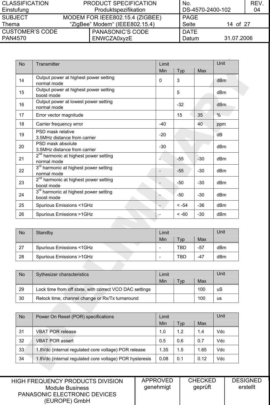
![CLASSIFICATION Einstufung PRODUCT SPECIFICATION Produktspezifikation No. DS-4570-2400-102 REV. 04 SUBJECT Thema MODEM FOR IEEE802.15.4 (ZIGBEE) “ZigBee” Modem“ (IEEE802.15.4) PAGE Seite 13 of 27 CUSTOMER’S CODE PAN4570 PANASONIC’S CODE ENWCZA0xyzE DATE Datum 31.07.2006 HIGH FREQUENCY PRODUCTS DIVISION Module Business PANASONIC ELECTRONIC DEVICES (EUROPE) GmbH APPROVED genehmigt CHECKED geprüft DESIGNED erstellt (4) In case the dc regulator option is mounted REG_OUT is connected to the regulator option output instead and the internal regulated core voltage is not accessible (5) In case the dc regulator option is mounted as regulator, use the REG_EN signal from EM250 (GPIO7) and connect it to REG_EN pin 46 and to an external high ohmic pull-up resistor tied to VBAT. The purpose is that during deep sleep the open collector output of REG_EN EM250 can disable the active-high enabled regulator in order to maintain low deep sleep currents. 13. A/D CONVERTER CHARACTERISTICS No Item 1 ATD characteristics refer to datasheet EM250 part 5.5 ADC Module 2 ATD timing/performance characteristics refer to datasheet EM250 part 5.5 ADC Module 14. AC ELECTRICAL CHARACTERISTICS VBAT = 3.0V, Tamb = 25°C, measured at 50Ω terminal load at pin 38 RF or U.FL socket, for all channels number 11,12,..., 26 according to [1] No Limit Unit Receiver Min Typ Max 1 Sensitivity for 1% Packet Error Rate (PER) -85 -96 - dBm 2 Sensitivity for 1% Packet Error Rate (PER) (boost mode) -85 -97 - dBm 3 Saturation (maximum input level for correct operation, low gain) 0 - - dBm 4 Adjacent Channel Rejection (1% PER and desired signal –82dBm acc. to [1]) 35 dB 5 Alternate Channel Rejection (1% PER and desired signal –82dBm acc. to [1]) 40 dB 6 Channel Rejection for all other channels (1% PER and desired signal –82dBm acc. to [1]) 40 dB 7 802.11g rejection centered at +12MHz or –13MHz (1% PER and desired signal –82dBm acc. to [1]) 40 dB 8 Co-channel rejection (1% PER and desired signal –82dBm acc. to [1]) -6 dBc 9 Relative frequency error (2x40ppm required by [1]) -120 120 ppm 10 Relative timing error (2x40ppm required by [1]) -120 120 ppm 11 Linear RSSI range 40 dB 12 Spurious Emissions <1GHz - TBD -57 dBm 13 Spurious Emissions >1GHz - TBD -47 dBm](https://usermanual.wiki/Panasonic-Devices-Europe/EM250A.user-manual/User-Guide-690108-Page-13.png)
![CLASSIFICATION Einstufung PRODUCT SPECIFICATION Produktspezifikation No. DS-4570-2400-102 REV. 04 SUBJECT Thema MODEM FOR IEEE802.15.4 (ZIGBEE) “ZigBee” Modem“ (IEEE802.15.4) PAGE Seite 15 of 27 CUSTOMER’S CODE PAN4570 PANASONIC’S CODE ENWCZA0xyzE DATE Datum 31.07.2006 HIGH FREQUENCY PRODUCTS DIVISION Module Business PANASONIC ELECTRONIC DEVICES (EUROPE) GmbH APPROVED genehmigt CHECKED geprüft DESIGNED erstellt 15. SOLDERING TEMPERATURE-TIME PROFILE (FOR REFLOW SOLDERING) Temperatur-Zeit Profil für die Reflowlötung 15.1. FOR LEAD SOLDER Recommended temp. profile for reflow soldering Temp.[°C] Time [s] 235°C max. 220 ±5°C 200°C150 ±10°C 90 ±30s 10 ±1s 30 +20/-10s 15.2. FOR LEAD FREE SOLDER Our used temp. profile for reflow soldering Temp.[°C] Time [s] 230°C -250°C max. 220°C150°C – 190°C 90 ±30s 30 +20/-10s Reflow permissible cycle: 2 Opposite side reflow is prohibited due to module weight.](https://usermanual.wiki/Panasonic-Devices-Europe/EM250A.user-manual/User-Guide-690108-Page-15.png)
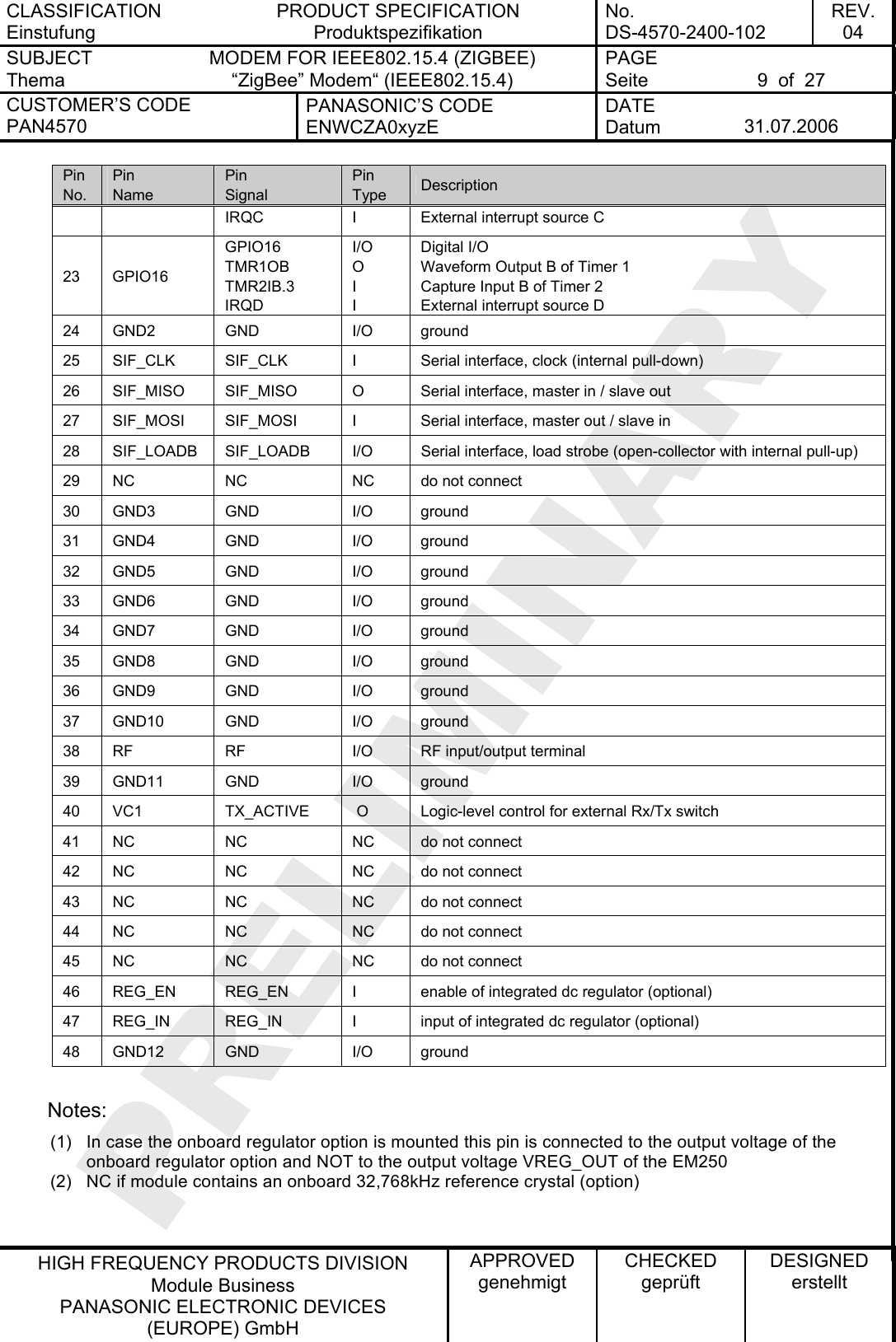
![CLASSIFICATION Einstufung PRODUCT SPECIFICATION Produktspezifikation No. DS-4570-2400-102 REV. 04 SUBJECT Thema MODEM FOR IEEE802.15.4 (ZIGBEE) “ZigBee” Modem“ (IEEE802.15.4) PAGE Seite 17 of 27 CUSTOMER’S CODE PAN4570 PANASONIC’S CODE ENWCZA0xyzE DATE Datum 31.07.2006 HIGH FREQUENCY PRODUCTS DIVISION Module Business PANASONIC ELECTRONIC DEVICES (EUROPE) GmbH APPROVED genehmigt CHECKED geprüft DESIGNED erstellt 18. LABELING DRAWING Kennzeichnung des Moduls durch Label 26,5 mm20,0 mmAntennaENWCZA0xyzE0201ES0000001060602FCC ID: T7VEM250A Imprint Aufdruck Description Beschreibung ENWCZA0xyzE This is the ordering code from Panasonic, details could be found under chapter 25. Date Code Production Date Code in the format YYMMDD, e.g. 060602 02 Indication for software revision for our final test, customer are able to flash there own software. 01ES Indication for the hardware revision, ES indicates the ES status, will be removed after MP ready. 0000001 Indication for the serial number. (FCC ID: T7VEM250A) This is the FCC ID in future, should be labelled only after FCC approval. 2D-Barcode Information in the 2D-Barcode are the serial number [7 signs], the ENW-Part-Number [11 signs], identifier for the software release [2 signs], the identifier for the hardware release [2 signs] and the production date code in the format Year-Month-Day [6 signs], separated by a semicolon. The IEEE802.15.4 MAC Address [12 characters] are stored in the Ember IC EM250, therefore it could not be on the label, but must be stored in the final test report to have a reference betweeen MAC address and serial number. 19. MECHANICAL REQUIREMENTS Mechanische Anforderungen No. Item Punkt Limit Grenzwerte Condition Bedingung 1 Solderability Lötfähigkeit More than 75% of the soldering area shall be coated by solder Mehr als 75% der Lötfläche soll mit Lötpaste bedeckt sein. Reflow soldering with recommendable temperature profile 2 Resistance to soldering heat It shall be satisfied electrical requirements and not be mechanical damage Please see chapter 15.2](https://usermanual.wiki/Panasonic-Devices-Europe/EM250A.user-manual/User-Guide-690108-Page-17.png)
![CLASSIFICATION Einstufung PRODUCT SPECIFICATION Produktspezifikation No. DS-4570-2400-102 REV. 04 SUBJECT Thema MODEM FOR IEEE802.15.4 (ZIGBEE) “ZigBee” Modem“ (IEEE802.15.4) PAGE Seite 19 of 27 CUSTOMER’S CODE PAN4570 PANASONIC’S CODE ENWCZA0xyzE DATE Datum 31.07.2006 HIGH FREQUENCY PRODUCTS DIVISION Module Business PANASONIC ELECTRONIC DEVICES (EUROPE) GmbH APPROVED genehmigt CHECKED geprüft DESIGNED erstellt 21. SOFTWARE Software Software tools In order to develop code and ZigBeeTM networks the Ember Insight Desktop Development Environment is required. This environment works with the preceeding EM2420, the EM250 and the upcoming EM260. For code development it comprises the Integrated Development Environment (IDE) named xIDE based on eclipse 3.1.0 for editing, compiling and debugging of C–applications. In addition network visualization and debugging tools are included. For programming the Ember Insight Adapter is required. This adaptor has to be linked to the computer where the Ember Insight Desktop is installed on over an Ethernet network connection. Before connecting PAN4570 to the Ember Insight Adaptor study the latest Ember Insight Adaptor documentation. The following pins of PAN4570 have to be connected to the signals on the debug connector of the Ember Insight adaptor: PAN4570 pin PAN4570 signal name Insight Adapter signal name various ground ground 1(6) VBAT 3.0Vdc 3 RESET RSTB 25 SIF_CLK SIF_CLK 26 SIF_MISO SIF_MISO 27 SIF_MOSI SIF_MOSI 28 SIF_LOADB SIF_LOADB as packet trace interface (PTI) also connect the following signals: 10 GPIO4 GPIO4 11 GPIO5 GPIO5 (6) only if the Ember Insight Adaptor is set to powering the target device PAN4570 Ember ZigBeeTM Stack EmberZNet (currently version 2.2) is the ZigBee stack provided with EM250. It supports as networking topologies true mesh, star and cluster networks. As ZigBee devices ZigBee Coordinator, ZigBee Full Fuctional Device and ZigBee End Devices are supported. For the ease of application programming EmberZNet is controlled by the application over API commands. Direct ZigBee APS layer APIs are provided for applications that require low level ZigBee control. According to [1] each ZigBee device has a unique address. This address is supplied with PAN4570 in a file containing a table with serial numbers and addresses.](https://usermanual.wiki/Panasonic-Devices-Europe/EM250A.user-manual/User-Guide-690108-Page-19.png)

![CLASSIFICATION Einstufung PRODUCT SPECIFICATION Produktspezifikation No. DS-4570-2400-102 REV. 04 SUBJECT Thema MODEM FOR IEEE802.15.4 (ZIGBEE) “ZigBee” Modem“ (IEEE802.15.4) PAGE Seite 26 of 27 CUSTOMER’S CODE PAN4570 PANASONIC’S CODE ENWCZA0xyzE DATE Datum 31.07.2006 HIGH FREQUENCY PRODUCTS DIVISION Module Business PANASONIC ELECTRONIC DEVICES (EUROPE) GmbH APPROVED genehmigt CHECKED geprüft DESIGNED erstellt 29. RELATED DOCUMENTS Mitgeltende Dokumente [1] IEEE Standard 802.15.4 –2003 Wireless Medium Access Control (MAC) and Physical Layer (PHY) Specifications for Low-Rate Wireless Personal Area Networks (LR-WPANs) [2] Data Sheet EM250, Ember Inc. (www.ember.com) [3] Data Sheet U.FL-Series 2004.2 Hirose Ultra Small Surface Mount Coaxial Connectors - Low Profile 1.9mm or 2.4mm Mated Height](https://usermanual.wiki/Panasonic-Devices-Europe/EM250A.user-manual/User-Guide-690108-Page-26.png)