Panasonic Devices Europe EM250A ZigBee module PAN4570 / ETRX2 User Manual 1
Panasonic Industrial Devices Europe GmbH ZigBee module PAN4570 / ETRX2 1
Contents
- 1. user manual
- 2. user manual 2
user manual

CLASSIFICATION
Einstufung
PRODUCT SPECIFICATION
Produktspezifikation
No.
DS-4570-2400-102
REV.
04
SUBJECT
Thema
MODEM FOR IEEE802.15.4 (ZIGBEE)
“ZigBee” Modem“ (IEEE802.15.4)
PAGE
Seite
1 of 27
CUSTOMER’S CODE
PAN4570
PANASONIC’S CODE
ENWCZA0xyzE
DATE
Datum
31.07.2006
HIGH FREQUENCY PRODUCTS DIVISION
Module Business
PANASONIC ELECTRONIC DEVICES
(EUROPE) GmbH
APPROVED
genehmigt
CHECKED
geprüft
DESIGNED
erstellt
Application for Production
Panasonic Electronic Devices (Europe) GmbH
Zeppelinstrasse 19
21337 Lüneburg
Applicant / Manufacturer
Hardware
Germany
Ember Inc.
Applicant / Manufacturer
Software
Contents Approval for Mass Production
Customer
CHECKED / APPROVED:
DATE: NAME: SIGNATURE:
NOTE:
AT LEAST ONE SET OF APPROVED SPECIFICATIONS SHOULD BE RETURNED TO
THE ADDRESS OF THE ISSUING PARTY.

CLASSIFICATION
Einstufung
PRODUCT SPECIFICATION
Produktspezifikation
No.
DS-4570-2400-102
REV.
04
SUBJECT
Thema
MODEM FOR IEEE802.15.4 (ZIGBEE)
“ZigBee” Modem“ (IEEE802.15.4)
PAGE
Seite
2 of 27
CUSTOMER’S CODE
PAN4570
PANASONIC’S CODE
ENWCZA0xyzE
DATE
Datum
31.07.2006
HIGH FREQUENCY PRODUCTS DIVISION
Module Business
PANASONIC ELECTRONIC DEVICES
(EUROPE) GmbH
APPROVED
genehmigt
CHECKED
geprüft
DESIGNED
erstellt
TABLE OF CONTENTS
1. Key Features...................................................................................................................4
2. Applications for the Module.............................................................................................4
3. Description of the Module................................................................................................5
3.1. On board DC Regulator .........................................................................................5
3.2. On Board reference Crystal ...................................................................................5
4. Scope of this Document ..................................................................................................6
5. History for this Document................................................................................................6
6. Terminal Layout...............................................................................................................7
7. Block Diagram...............................................................................................................10
8. Key Parts List ................................................................................................................10
9. Test Conditions .............................................................................................................10
10. Absolute Maximum Ratings...........................................................................................11
11. Operating Conditions.....................................................................................................11
12. DC Electrical Characteristics.........................................................................................12
13. A/D converter Characteristics........................................................................................13
14. AC Electrical Characteristics.........................................................................................13
15. Soldering Temperature-time profile (for reflow soldering).............................................15
15.1. For lead solder .....................................................................................................15
15.2. For lead free solder..............................................................................................15
16. Module Dimensions.......................................................................................................16
17. Foot Print of the Module................................................................................................16
18. Labeling Drawing...........................................................................................................17
19. Mechanical Requirements.............................................................................................17
20. Recommended Land Pattern ........................................................................................18
21. Software ........................................................................................................................19
22. Reliability Tests .............................................................................................................20
23. Packaging......................................................................................................................20
24. Application Notes ..........................................................................................................20
24.1. Cautions for safety ...............................................................................................20
24.2. Design engineering notes ....................................................................................21
24.3. Storage conditions ...............................................................................................22
25. Ordering Information .....................................................................................................22
26. RoHS Declaration..........................................................................................................23
27. Data Sheet Status .........................................................................................................23
28. Regulatory Information..................................................................................................24
28.1. FCC Notice ..........................................................................................................24
28.2. Caution.................................................................................................................24
28.3. Labeling Requirements ........................................................................................24

CLASSIFICATION
Einstufung
PRODUCT SPECIFICATION
Produktspezifikation
No.
DS-4570-2400-102
REV.
04
SUBJECT
Thema
MODEM FOR IEEE802.15.4 (ZIGBEE)
“ZigBee” Modem“ (IEEE802.15.4)
PAGE
Seite
3 of 27
CUSTOMER’S CODE
PAN4570
PANASONIC’S CODE
ENWCZA0xyzE
DATE
Datum
31.07.2006
HIGH FREQUENCY PRODUCTS DIVISION
Module Business
PANASONIC ELECTRONIC DEVICES
(EUROPE) GmbH
APPROVED
genehmigt
CHECKED
geprüft
DESIGNED
erstellt
28.4. Antenna Warning .................................................................................................25
28.5. Approved Antenna List.........................................................................................25
28.6. RF Exposure PAN4570........................................................................................25
29. Related Documents.......................................................................................................26
30. General Information.......................................................................................................27
31. Life Support Policy ........................................................................................................27

CLASSIFICATION
Einstufung
PRODUCT SPECIFICATION
Produktspezifikation
No.
DS-4570-2400-102
REV.
04
SUBJECT
Thema
MODEM FOR IEEE802.15.4 (ZIGBEE)
“ZigBee” Modem“ (IEEE802.15.4)
PAGE
Seite
4 of 27
CUSTOMER’S CODE
PAN4570
PANASONIC’S CODE
ENWCZA0xyzE
DATE
Datum
31.07.2006
HIGH FREQUENCY PRODUCTS DIVISION
Module Business
PANASONIC ELECTRONIC DEVICES
(EUROPE) GmbH
APPROVED
genehmigt
CHECKED
geprüft
DESIGNED
erstellt
1. KEY FEATURES
Schlüsseleigenschaften
• short range 2,4GHz ISM band IEEE802.15.4 [1] compliant transceiver
• Complete system based on the ZigBeeTM compliant platform EM250 that combines the
transceiver with a powerful, efficient industry proven 16-bit microprocessor with
comprehensive hardware supported network-level debugging features
• designed specifically for use with EmberZNet, Embers ZigBee compliant embedded
mesh networking
• powerful 16-bit microprocessor
• 128k flash ROM and 5k of SRAM memory
• high Rx sensitivity of –97dBm at 1% Packet Error Rate
• 3dBm Tx maximum output power with power control over 20dB range
• Small size 20mm x 26,5mm x 3,0mm
• single port antenna terminal (pcb pad, U.FL socket or chip antenna versions available)
• Integrated ADC module with 12-bit resolution
• two 16-bit general purpose timers; one 16-bit sleep timer
• 17 GPIO pins with alternate functions
• two sleep modes for increased battery life
• low voltage detect/reset
• complies with ETSI EN300 328 and FCC part 15
2. APPLICATIONS FOR THE MODULE
Anwendungen für das Modul
• ZigBeeTM FFD (full functional) and RFD (reduced functional) devices working in star
and mesh networks
• Wireless sensor and actuator networks
• Remote control and wire replacement in industrial systems
• Building automation and control
• Inventory and logistics management
• HID (Human Interface Devices)
• Toys
• Home gateways

CLASSIFICATION
Einstufung
PRODUCT SPECIFICATION
Produktspezifikation
No.
DS-4570-2400-102
REV.
04
SUBJECT
Thema
MODEM FOR IEEE802.15.4 (ZIGBEE)
“ZigBee” Modem“ (IEEE802.15.4)
PAGE
Seite
5 of 27
CUSTOMER’S CODE
PAN4570
PANASONIC’S CODE
ENWCZA0xyzE
DATE
Datum
31.07.2006
HIGH FREQUENCY PRODUCTS DIVISION
Module Business
PANASONIC ELECTRONIC DEVICES
(EUROPE) GmbH
APPROVED
genehmigt
CHECKED
geprüft
DESIGNED
erstellt
3. DESCRIPTION OF THE MODULE
Beschreibung des Moduls
PAN4570 contains the single chip EM250 [2] from Ember Inc., a 24MHz reference crystal and
RF frontend circuitry optimized for best RF performance. As single ended RF output the module
is available with integrated antenna or 50ohms or U.FL male socket [3] or 50 ohms pad terminal
on the bottom of the module.
Two additional hardware options are available on request:
3.1. ON BOARD DC REGULATOR
Although the EM250 already contains a dc regulator internally, the module can be
requested with an extra onboard linear low dropout (LDO) regulator. Some applications
could benefit from this additional regulator because as of for example:
(1) Further extension of the input voltage range or
(2) Extented battery life by replacing the regulator within EM250 by a special ultra low
quiescent current regulator or
(3) allowing for operation on very noisy power supplies
3.2. ON BOARD REFERENCE CRYSTAL
A second option that is available is an on board 32,768kHz crystal reference. This option is
provided for applications that require a precision reference clock.
Where a precision 32,768kHz reference is already available on the applicationboard, it
could be fed to pin 4 instead and this option is not needed.
Please contact the manufacturer if one of the options could be useful for your product design.
PAN4570 is used for ZigBeeTM (www.zigbee.org) applications working with
EmberZNetTM of Ember Inc. (www.ember.com). EmberZNetTM is a fully ZigBeeTM compliant
networking stack. For code development Insight DesktopTM, a comprehensive
integrated development environment (IDE) and C-language compiler toolchain from
Ember Inc. is required. Insight DesktopTM is part of Ember development kits and
can currently be purchased together with programming adaptors as EM250 jumpstart kit at a
price of USD 2500,- directly from Ember Inc. (www.ember.com).
When using ZigBeeTM technology for a product the following additional costs have to
be taken into account:
1. Membership of the ZigBeeTM alliance, as least as adopter member for US$ 3500,-.
2. The cost of a ZigBeeTM product certification at a testhouse (TÜV Rheinland) ranges from
approximately US$ 4000,- to US$ 10000,-, depending on the implemented software.
3. Products qualifying for ZigBeeTM certification at the ZigBeeTM alliance need a logo
CLASSIFICATION
Einstufung
PRODUCT SPECIFICATION
Produktspezifikation
No.
DS-4570-2400-102
REV.
04
SUBJECT
Thema
MODEM FOR IEEE802.15.4 (ZIGBEE)
“ZigBee” Modem“ (IEEE802.15.4)
PAGE
Seite
6 of 27
CUSTOMER’S CODE
PAN4570
PANASONIC’S CODE
ENWCZA0xyzE
DATE
Datum
31.07.2006
HIGH FREQUENCY PRODUCTS DIVISION
Module Business
PANASONIC ELECTRONIC DEVICES
(EUROPE) GmbH
APPROVED
genehmigt
CHECKED
geprüft
DESIGNED
erstellt
administration fee of USD 1000,- for the first product, and USD 500,- for each additional
product.
For more details on ZigBeeTM software see also part 21.
4. SCOPE OF THIS DOCUMENT
Umfang dieses Dokumentes
This product specification applies to the ZigBee ready modem ENWCZA0xyzE.
The characters xyz indicate different versions (refer to part 22 Ordering Information).
The used chip is the EM250 from the US company Ember Inc. www.ember.com.
Diese Produktionsunterlagen beziehen sich auf das ZigBee ready Modem ENWCZA0xyzE
Die Zeichen xyz bezeichnen verschiedene Versionen (Erklärung im Kapitel 25 Ordering
Information). Der verwendete ZigBee Chip ist EM250 der US Firma Ember Inc..
5. HISTORY FOR THIS DOCUMENT
Versionsverwaltung dieses Dokumentes
Revision
Version
Date
Datum
Modification / Remarks
Änderungen / Bemerkungen
01 19.05.2006 preliminary draft version
02 10.07.2006 ordering part number update, some minor corrections
03 27.07.2006 update chapter Labeling Drawing
04 31.07.2006 Add chapter Regulatory Information, correct chapter Block Diagram
CLASSIFICATION
Einstufung
PRODUCT SPECIFICATION
Produktspezifikation
No.
DS-4570-2400-102
REV.
04
SUBJECT
Thema
MODEM FOR IEEE802.15.4 (ZIGBEE)
“ZigBee” Modem“ (IEEE802.15.4)
PAGE
Seite
7 of 27
CUSTOMER’S CODE
PAN4570
PANASONIC’S CODE
ENWCZA0xyzE
DATE
Datum
31.07.2006
HIGH FREQUENCY PRODUCTS DIVISION
Module Business
PANASONIC ELECTRONIC DEVICES
(EUROPE) GmbH
APPROVED
genehmigt
CHECKED
geprüft
DESIGNED
erstellt
6. TERMINAL LAYOUT
Anschlußbelegung
Top View
25
1
2
3
4
5
6
7
8
9
10
41
40
39
38
37 42 43 44 46
45
31
30
29
28
27
26,5 mm
20,0 mm
Height
3,0 mm
26
47 48
20
21
22
23
24 19
18 17 15
16 14
13
11
12
32
33
34
35
36
Antenna
Pin
No.
Pin
Name
Pin
Signal
Pin
Type Description
1 VBAT VBAT I module dc supply voltage
2 REG_OUT REG_OUT O output of EM250 regulator voltage VREG_OUT (1)
3 RESET RESET I reset of module
4 OSC32A OSC32A I/O 32.768kHz clock input (2)
5 OSC32B OSC32B I/O NC
6 GPIO0
GPIO0
MOSI
MOSI
TMR1IA.1
I/O
O
I
I
Digital I/O
SPI master data out of serial controller SC2
SPI slave data in of serial controller SC2
Capture Input A of Timer 1
7 GPIO1
GPIO1
MISO
MISO
SDA
TMR2IA.2
I/O
I
O
I/O
I
Digital I/O
SPI master data in of Serial Controller SC2
SPI slave data out of Serial Controller SC2
I2C data of Serial Controller SC2
Capture Input A of Timer 2
8
GPIO2
GPIO2
MSCLK
MSCLK
SCL
I/O
O
I
I/O
Digital I/O
SPI master clock of Serial Controller SC2
SPI slave clock of Serial Controller SC2
I2C clock of Serial Controller SC2
CLASSIFICATION
Einstufung
PRODUCT SPECIFICATION
Produktspezifikation
No.
DS-4570-2400-102
REV.
04
SUBJECT
Thema
MODEM FOR IEEE802.15.4 (ZIGBEE)
“ZigBee” Modem“ (IEEE802.15.4)
PAGE
Seite
8 of 27
CUSTOMER’S CODE
PAN4570
PANASONIC’S CODE
ENWCZA0xyzE
DATE
Datum
31.07.2006
HIGH FREQUENCY PRODUCTS DIVISION
Module Business
PANASONIC ELECTRONIC DEVICES
(EUROPE) GmbH
APPROVED
genehmigt
CHECKED
geprüft
DESIGNED
erstellt
Pin
No.
Pin
Name
Pin
Signal
Pin
Type Description
TMR2IB.2 I Capture Input B of Timer 2
9
GPIO3
GPIO3
SSEL
TMR1IB.1
I/O
I
I
Digital I/O
SPI slave select of Serial Controller SC2
Capture Input B of Timer 1
10
GPIO4
GPIO4
ADC0
PTI_EN
I/O
Analog
O
Digital I/O
ADC Input 0
Frame signal of Packet Trace Interface (PTI)
11
GPIO5
GPIO5
ADC1
PTI_DATA
I/O
Analog
O
Digital I/O
ADC Input 1
Data signal of Packet Trace Interface (PTI)
12
GPIO6
GPIO6
ADC2
TMR2CLK
TMR1ENMSK
I/O
Analog
I
I
Digital I/O
ADC Input 2
External clock input of Timer 2
External enable mask of Timer 1
13 GND1 GND I/O ground
14
GPIO7
GPIO7
ADC3
REG_EN
I/O
Analog
O
Digital I/O
ADC Input 3
External regulator open collector output
15
GPIO8
GPIO8
VREF_OUT
TMR1CLK
TMR2ENMSK
IRQA
I/O
Analog
I
I
I
Digital I/O
ADC reference output
External clock input of Timer 1
External enable mask of Timer 2
External interupt source A
16
GPIO9
GPIO9
TXD
MO
MSDA
TMR1IA.2
I/O
O
O
I/O
I
Digital I/O
UART transmit data of Serial Controller SC1
SPI master data out of Serial Controller SC1
I2C data of Serial Controller SC2
Capture Input A of Timer 1
17 GPIO10
GPIO10
RXD
MI
MSCL
TMR1IB.2
I/O
I
I
I/O
I
Digital I/O
UART receive data of Serial Controller SC1
SPI master data in of Serial Controller SC1
I2C clock of Serial Controller SC1
Capture Input B of Timer 2
18
GPIO11
GPIO11
CTS
MCLK
TMR2IA.1
I/O
I
O
I
Digital I/O
UART CTS handshake of Serial Controller SC1
SPI master clock of Serial Controller SC1
Capture Input A of Timer 2
19
GPIO12
GPIO12
RTS
TMR2IB.1
I/O
O
I
Digital I/O
UART RTS handshake of Serial Controller SC1
Capture Input B for Timer 2
20
GPIO13
GPIO13
TMR2OA
TMR1IA.3
I/O
O
I
Digital I/O
Waveform Output A of Timer 2
Capture Input A of Timer 1
21
GPIO14
GPIO14
TMR2OB
TMR1IB.3
IRQB
I/O
O
I
I
Digital I/O
Waveform Output B of Timer 2
Capture Input B of Timer 1
External interrupt source B
22
GPIO15
GPIO15
TMR1OA
TMR2IA.3
I/O
O
I
Digital I/O
Waveform Output A of Timer 1
Capture Input A of Timer 2
CLASSIFICATION
Einstufung
PRODUCT SPECIFICATION
Produktspezifikation
No.
DS-4570-2400-102
REV.
04
SUBJECT
Thema
MODEM FOR IEEE802.15.4 (ZIGBEE)
“ZigBee” Modem“ (IEEE802.15.4)
PAGE
Seite
9 of 27
CUSTOMER’S CODE
PAN4570
PANASONIC’S CODE
ENWCZA0xyzE
DATE
Datum
31.07.2006
HIGH FREQUENCY PRODUCTS DIVISION
Module Business
PANASONIC ELECTRONIC DEVICES
(EUROPE) GmbH
APPROVED
genehmigt
CHECKED
geprüft
DESIGNED
erstellt
Pin
No.
Pin
Name
Pin
Signal
Pin
Type Description
IRQC I External interrupt source C
23
GPIO16
GPIO16
TMR1OB
TMR2IB.3
IRQD
I/O
O
I
I
Digital I/O
Waveform Output B of Timer 1
Capture Input B of Timer 2
External interrupt source D
24 GND2 GND I/O ground
25 SIF_CLK SIF_CLK I Serial interface, clock (internal pull-down)
26 SIF_MISO SIF_MISO O Serial interface, master in / slave out
27 SIF_MOSI SIF_MOSI I Serial interface, master out / slave in
28 SIF_LOADB SIF_LOADB I/O Serial interface, load strobe (open-collector with internal pull-up)
29 NC NC NC do not connect
30 GND3 GND I/O ground
31 GND4 GND I/O ground
32 GND5 GND I/O ground
33 GND6 GND I/O ground
34 GND7 GND I/O ground
35 GND8 GND I/O ground
36 GND9 GND I/O ground
37 GND10 GND I/O ground
38 RF RF I/O RF input/output terminal
39 GND11 GND I/O ground
40 VC1 TX_ACTIVE O Logic-level control for external Rx/Tx switch
41 NC NC NC do not connect
42 NC NC NC do not connect
43 NC NC NC do not connect
44 NC NC NC do not connect
45 NC NC NC do not connect
46 REG_EN REG_EN I enable of integrated dc regulator (optional)
47 REG_IN REG_IN I input of integrated dc regulator (optional)
48 GND12 GND I/O ground
Notes:
(1) In case the onboard regulator option is mounted this pin is connected to the output voltage of the
onboard regulator option and NOT to the output voltage VREG_OUT of the EM250
(2) NC if module contains an onboard 32,768kHz reference crystal (option)
CLASSIFICATION
Einstufung
PRODUCT SPECIFICATION
Produktspezifikation
No.
DS-4570-2400-102
REV.
04
SUBJECT
Thema
MODEM FOR IEEE802.15.4 (ZIGBEE)
“ZigBee” Modem“ (IEEE802.15.4)
PAGE
Seite
10 of 27
CUSTOMER’S CODE
PAN4570
PANASONIC’S CODE
ENWCZA0xyzE
DATE
Datum
31.07.2006
HIGH FREQUENCY PRODUCTS DIVISION
Module Business
PANASONIC ELECTRONIC DEVICES
(EUROPE) GmbH
APPROVED
genehmigt
CHECKED
geprüft
DESIGNED
erstellt
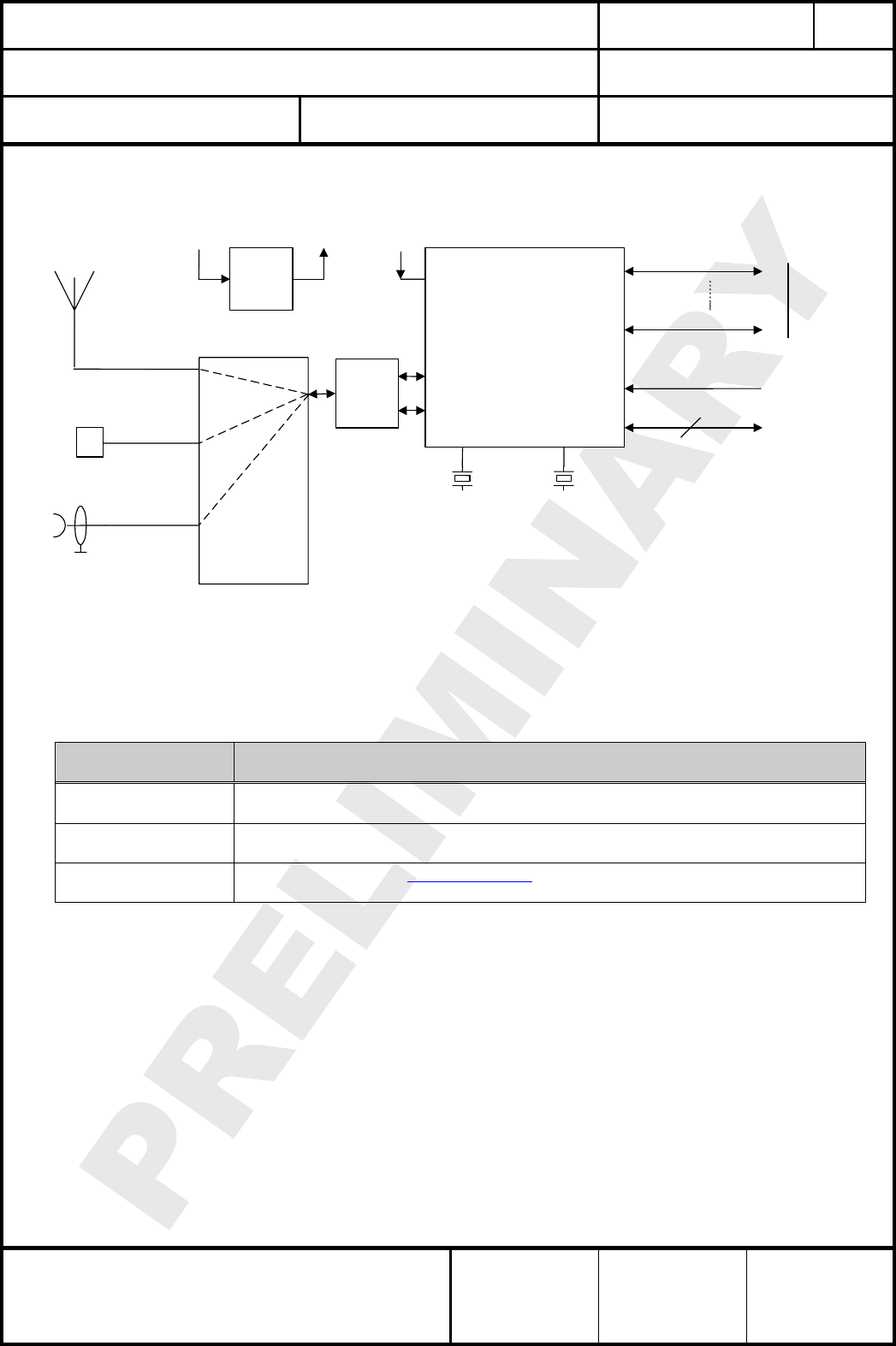
7. BLOCK DIAGRAM
Blockdiagramm
24MHz 32,768kHz
(optional)
EM250
RF transceiver 2,4GHz
16-bit XAP2b uC
128kB flash / 5k RAM
GPIO0
GPIO16
I / O
programming
4 SIF
LDO
(optional)
VBAT
REG_IN REG_OUT
RESET RESET
BALUN
integrated
antenna
pad
U.FL socket
rf
terminal
selection,
filtering and
matching
circuitry
8. KEY PARTS LIST
Liste der Schlüsselkomponenten
Part Name
Teilenummer
Material
Material
P.W.Board
Leiterplatte
Glass cloth epoxide resin with gold plating
FR4 mit Goldauflage
Casing
Deckel CuNi18Zn20 (EN)
RF-IC part name
RF IC Name
EM250 from Ember Inc.(www.ember.com)
9. TEST CONDITIONS
Meßbedingungen
Measurements shall be made under room temperature and humidity unless otherwise specified.
Messungen unter normalen Bedingungen, Abweichungen sind gesondert notiert.
Temperature 25 ± 10°C Humidity 40 to 85%RH
Temperatur 25 ± 10°C Luftfeuchtigkeit 40 to 85%RH
CLASSIFICATION
Einstufung
PRODUCT SPECIFICATION
Produktspezifikation
No.
DS-4570-2400-102
REV.
04
SUBJECT
Thema
MODEM FOR IEEE802.15.4 (ZIGBEE)
“ZigBee” Modem“ (IEEE802.15.4)
PAGE
Seite
11 of 27
CUSTOMER’S CODE
PAN4570
PANASONIC’S CODE
ENWCZA0xyzE
DATE
Datum
31.07.2006
HIGH FREQUENCY PRODUCTS DIVISION
Module Business
PANASONIC ELECTRONIC DEVICES
(EUROPE) GmbH
APPROVED
genehmigt
CHECKED
geprüft
DESIGNED
erstellt
10. ABSOLUTE MAXIMUM RATINGS
Absolute Grenzwerte
The maximum ratings may not be exceeded under any circumstances, not even momentarily
and individually, as permanent damage to the module will result.
No. Item
Punkt
Symbol
Zeichen
Absolute Maximum Ratings
Absolute Grenzwerte
Unit
Einheit
1 Supply voltage VBAT -0.1 to +3.6 Vdc
2
Voltage on any GPIO[16:0] ,
SIF_CLK, SIF_MISO,
SIF_MOSI, SIF_LOADB,
OSC32A, OSC32B, RESET,
REG_OUT
Vin -0.3 to VBAT+0.3 Vdc
3 Voltage on VC1 Vin 2.0 Vdc
4 Storage temperature range Tstg -40 to +105 °C
5 Operating temperature range Top -40 to +85 °C
6 Input RF level Pmax 0 dBm
7
ESD on any pin(3) according to
Human Body Model (HBM)
circuit description
VTHHBM ±2 kV
8 Lead temperature
Löttemperatur TDeath Please see chapter 15.2 °C
Notes:
(3) Input must be current limited to the value specified
11. OPERATING CONDITIONS
Betriebsbedingungen
No. Item Condition / Remark Symbol Value Unit
Min Typ Max
1 Supply voltage The typical value
is recommended
VDD 2.1 3.0 3.6 Vdc
2 RF Input Frequency fC 2405 2480 MHz
3 RF Input Power pIN 0 dBm
4 maximum Tx output power Tx normal mode pout 3 dBm
5 Return loss of load applied to
RF terminals pin 38 or U.FL
50Ω is reference
load
a -10 0 dB
6 Logic Input Voltage Low VIL 0 0.2x
VBAT V
7 Logic Input Voltage High VIH 0.8x
VBAT VBAT V
8 SPI clock rate The typical value is
recommended
fSPI 12 MHz
9 Operating temperature range Top -40 +85 °C
CLASSIFICATION
Einstufung
PRODUCT SPECIFICATION
Produktspezifikation
No.
DS-4570-2400-102
REV.
04
SUBJECT
Thema
MODEM FOR IEEE802.15.4 (ZIGBEE)
“ZigBee” Modem“ (IEEE802.15.4)
PAGE
Seite
12 of 27
CUSTOMER’S CODE
PAN4570
PANASONIC’S CODE
ENWCZA0xyzE
DATE
Datum
31.07.2006
HIGH FREQUENCY PRODUCTS DIVISION
Module Business
PANASONIC ELECTRONIC DEVICES
(EUROPE) GmbH
APPROVED
genehmigt
CHECKED
geprüft
DESIGNED
erstellt
12. DC ELECTRICAL CHARACTERISTICS
VBAT = 3.0V, Tamb = 25°C if nothing else stated
No. Item Condition / Remark Symbol Value Unit
Min Typ Max
1 Module supply voltage VBAT VBAT 2.1 3.0 3.6 Vdc
2 Internal regulated core voltage
connected to
REG_OUT pin 2(4) VCORE 1.7 1.8 1.9 Vdc
3 Quiescent current, including
internal RC oscillator(5) 1.0 uA
4 Quiescent current, including
32,768kHz oscillator(5) 1.5 uA
5 Transmit current consumption total at +3dBm maximum
output power
ITX 35.5 mA
6 Transmit current consumption
total at +5dBm maximum
output power
at boost mode
ITX
41.5 mA
7 Transmit current consumption total at -32dBm minimum
output power
IDDT 28 mA
8 Receive current consumption total IRX 35.5 mA
9 Receive current consumption total (boost mode) IRX 37.5 mA
10 External load on internal
regulated core voltage
connected to
REG_OUT pin 2(4)
IRX 2 mA
11 Input voltage for logic 0 VIL 0
0.2x
VBAT Vdc
12 input voltage for logic 1 VIH 0.8x
VBAT VBAT Vdc
13 Input current for logic 0 IIL -0.5 uA
14 input current for logic 1 IIH 0.5 uA
15 input pull-up resistor value RIPU 30
kΩ
16 input pull-down resistor value RIPD 30
kΩ
17 Output voltage for logic 0 VOL 0
0.18x
VBAT Vdc
18 Output voltage for logic 1 VOH 0.82x
VBAT VBAT Vdc
19 Output source current
(standard current pad) IOHS 4 mA
20 Output sink current
(standard current pad) IOLS 4 mA
21 Output source current (high
current pad: GPIO[16:13] ) IOHH 8 mA
22 Output sink current (high
current pad: GPIO[16:13] ) IOLH 8 mA
23 Total output current
for I/O pads IOH +
IOL 40 mA
24 Input voltage threshold for
OSC32A 0.2 0.8x
VBAT Vdc
25 Output voltage level for VC1
VVC1
0.18x
VBAT 0.82x
VBAT Vdc
CLASSIFICATION
Einstufung
PRODUCT SPECIFICATION
Produktspezifikation
No.
DS-4570-2400-102
REV.
04
SUBJECT
Thema
MODEM FOR IEEE802.15.4 (ZIGBEE)
“ZigBee” Modem“ (IEEE802.15.4)
PAGE
Seite
13 of 27
CUSTOMER’S CODE
PAN4570
PANASONIC’S CODE
ENWCZA0xyzE
DATE
Datum
31.07.2006
HIGH FREQUENCY PRODUCTS DIVISION
Module Business
PANASONIC ELECTRONIC DEVICES
(EUROPE) GmbH
APPROVED
genehmigt
CHECKED
geprüft
DESIGNED
erstellt
(4) In case the dc regulator option is mounted REG_OUT is connected to the regulator option output
instead and the internal regulated core voltage is not accessible
(5) In case the dc regulator option is mounted as regulator, use the REG_EN signal from EM250 (GPIO7)
and connect it to REG_EN pin 46 and to an external high ohmic pull-up resistor tied to VBAT. The
purpose is that during deep sleep the open collector output of REG_EN EM250 can disable the active-
high enabled regulator in order to maintain low deep sleep currents.
13. A/D CONVERTER CHARACTERISTICS
No Item
1 ATD characteristics refer to datasheet EM250 part 5.5 ADC Module
2 ATD timing/performance
characteristics refer to datasheet EM250 part 5.5 ADC Module
14. AC ELECTRICAL CHARACTERISTICS
VBAT = 3.0V, Tamb = 25°C, measured at 50Ω terminal load at pin 38 RF or U.FL socket,
for all channels number 11,12,..., 26 according to [1]
No Limit Unit
Receiver
Min Typ Max
1 Sensitivity for 1% Packet Error Rate (PER) -85 -96 - dBm
2 Sensitivity for 1% Packet Error Rate (PER)
(boost mode) -85 -97 - dBm
3 Saturation (maximum input level for correct operation,
low gain) 0 - - dBm
4 Adjacent Channel Rejection
(1% PER and desired signal –82dBm acc. to [1]) 35 dB
5 Alternate Channel Rejection
(1% PER and desired signal –82dBm acc. to [1]) 40 dB
6 Channel Rejection for all other channels
(1% PER and desired signal –82dBm acc. to [1]) 40 dB
7 802.11g rejection centered at +12MHz or –13MHz
(1% PER and desired signal –82dBm acc. to [1]) 40 dB
8 Co-channel rejection
(1% PER and desired signal –82dBm acc. to [1]) -6 dBc
9 Relative frequency error
(2x40ppm required by [1]) -120 120 ppm
10 Relative timing error
(2x40ppm required by [1]) -120 120 ppm
11 Linear RSSI range 40 dB
12 Spurious Emissions <1GHz - TBD -57 dBm
13 Spurious Emissions >1GHz - TBD -47 dBm
CLASSIFICATION
Einstufung
PRODUCT SPECIFICATION
Produktspezifikation
No.
DS-4570-2400-102
REV.
04
SUBJECT
Thema
MODEM FOR IEEE802.15.4 (ZIGBEE)
“ZigBee” Modem“ (IEEE802.15.4)
PAGE
Seite
14 of 27
CUSTOMER’S CODE
PAN4570
PANASONIC’S CODE
ENWCZA0xyzE
DATE
Datum
31.07.2006
HIGH FREQUENCY PRODUCTS DIVISION
Module Business
PANASONIC ELECTRONIC DEVICES
(EUROPE) GmbH
APPROVED
genehmigt
CHECKED
geprüft
DESIGNED
erstellt
No Limit Unit
Transmitter
Min Typ Max
14 Output power at highest power setting
normal mode 0 3 dBm
15 Output power at highest power setting
boost mode 5 dBm
16 Output power at lowest power setting
normal mode -32 dBm
17 Error vector magnitude 15 35 %
18 Carrier frequency error -40 40 ppm
19 PSD mask relative
3.5MHz distance from carrier -20 dB
20 PSD mask absolute
3.5MHz distance from carrier -30 dBm
21 2nd harmonic at highest power setting
normal mode - -55 -30 dBm
22 3rd harmonic at highest power setting
normal mode - -55 -30 dBm
23 2nd harmonic at highest power setting
boost mode - -50 -30 dBm
24 3rd harmonic at highest power setting
boost mode - -50 -30 dBm
25 Spurious Emissions <1GHz - < -54 -36 dBm
26 Spurious Emissions >1GHz - < -60 -30 dBm
No Limit Unit
Standby
Min Typ Max
27 Spurious Emissions <1GHz - TBD -57 dBm
28 Spurious Emissions >1GHz - TBD -47 dBm
No Limit Unit
Sythesizer characteristics
Min Typ Max
29 Lock time from off state, with correct VCO DAC settings 100 uS
30 Relock time, channel change or Rx/Tx turnaround 100 us
No Limit Unit
Power On Reset (POR) specifications
Min Typ Max
31 VBAT POR release 1.0 1.2 1.4 Vdc
32 VBAT POR assert 0.5 0.6 0.7 Vdc
33 1.8Vdc (internal regulated core voltage) POR release 1.35 1.5 1.65 Vdc
34 1.8Vdc (internal regulated core voltage) POR hysteresis 0.08 0.1 0.12 Vdc
CLASSIFICATION
Einstufung
PRODUCT SPECIFICATION
Produktspezifikation
No.
DS-4570-2400-102
REV.
04
SUBJECT
Thema
MODEM FOR IEEE802.15.4 (ZIGBEE)
“ZigBee” Modem“ (IEEE802.15.4)
PAGE
Seite
15 of 27
CUSTOMER’S CODE
PAN4570
PANASONIC’S CODE
ENWCZA0xyzE
DATE
Datum
31.07.2006
HIGH FREQUENCY PRODUCTS DIVISION
Module Business
PANASONIC ELECTRONIC DEVICES
(EUROPE) GmbH
APPROVED
genehmigt
CHECKED
geprüft
DESIGNED
erstellt
15. SOLDERING TEMPERATURE-TIME PROFILE (FOR REFLOW SOLDERING)
Temperatur-Zeit Profil für die Reflowlötung
15.1. FOR LEAD SOLDER
Recommended temp. profile
for reflow soldering
Tem
p
.
[
°C
]
Time [s]
235°C max.
220 ±5°C
200°C
150 ±10°C
90 ±30s
10
±
1s
30 +20/-10s
15.2. FOR LEAD FREE SOLDER
Our used temp. profile
for reflow soldering
Temp.[°C]
Time [s]
230°C -250°C max.
220°C
150°C – 190°C
90 ±30s
30 +20/-10s
Reflow permissible cycle: 2
Opposite side reflow is prohibited due to module weight.
CLASSIFICATION
Einstufung
PRODUCT SPECIFICATION
Produktspezifikation
No.
DS-4570-2400-102
REV.
04
SUBJECT
Thema
MODEM FOR IEEE802.15.4 (ZIGBEE)
“ZigBee” Modem“ (IEEE802.15.4)
PAGE
Seite
16 of 27
CUSTOMER’S CODE
PAN4570
PANASONIC’S CODE
ENWCZA0xyzE
DATE
Datum
31.07.2006
HIGH FREQUENCY PRODUCTS DIVISION
Module Business
PANASONIC ELECTRONIC DEVICES
(EUROPE) GmbH
APPROVED
genehmigt
CHECKED
geprüft
DESIGNED
erstellt
16. MODULE DIMENSIONS
Modulabmessungen
No. Item
Punkt
Dimension
Abmessung
Tolerance
Toleranz
Remark
Bemerkung
1 Width 20.00 ± 0.20
2 Lenght 26.50 ± 0.20
3 Height 2.80 ± 0.20 With case
17. FOOT PRINT OF THE MODULE
Lötpads vom Modul
Top View
26,5 mm
20,0 mm
Antenna
48 x 1.00
4 x P1 = 0.70 40 x P2 = 0.40
48 x 1.00
0.10 around the edges
Pin 1
Sign "1" on the Module
(Bottom Side)
Pad
48 x 1.00 x 1.00
2.00
2.30
Dimensions in mm.
CLASSIFICATION
Einstufung
PRODUCT SPECIFICATION
Produktspezifikation
No.
DS-4570-2400-102
REV.
04
SUBJECT
Thema
MODEM FOR IEEE802.15.4 (ZIGBEE)
“ZigBee” Modem“ (IEEE802.15.4)
PAGE
Seite
17 of 27
CUSTOMER’S CODE
PAN4570
PANASONIC’S CODE
ENWCZA0xyzE
DATE
Datum
31.07.2006
HIGH FREQUENCY PRODUCTS DIVISION
Module Business
PANASONIC ELECTRONIC DEVICES
(EUROPE) GmbH
APPROVED
genehmigt
CHECKED
geprüft
DESIGNED
erstellt
18. LABELING DRAWING
Kennzeichnung des Moduls durch Label
26,5 mm
20,0 mm
Antenna
ENWCZA0xyzE
02
01ES
0000001
060602
FCC ID: T7VEM250A
Imprint
Aufdruck
Description
Beschreibung
ENWCZA0xyzE This is the ordering code from Panasonic, details could be found under chapter 25.
Date Code Production Date Code in the format YYMMDD, e.g. 060602
02 Indication for software revision for our final test, customer are able to flash there own
software.
01ES Indication for the hardware revision, ES indicates the ES status, will be removed after MP
ready.
0000001 Indication for the serial number.
(FCC ID: T7VEM250A) This is the FCC ID in future, should be labelled only after FCC approval.
2D-Barcode
Information in the 2D-Barcode are the serial number [7 signs], the ENW-Part-Number [11
signs], identifier for the software release [2 signs], the identifier for the hardware release [2
signs] and the production date code in the format Year-Month-Day [6 signs], separated by
a semicolon.
The IEEE802.15.4 MAC Address [12 characters] are stored in the Ember IC EM250,
therefore it could not be on the label, but must be stored in the final test report to have a
reference betweeen MAC address and serial number.
19. MECHANICAL REQUIREMENTS
Mechanische Anforderungen
No. Item
Punkt
Limit
Grenzwerte
Condition
Bedingung
1 Solderability
Lötfähigkeit
More than 75% of the soldering area shall be
coated by solder
Mehr als 75% der Lötfläche soll mit Lötpaste
bedeckt sein.
Reflow soldering with
recommendable temperature
profile
2 Resistance to
soldering heat
It shall be satisfied electrical requirements and
not be mechanical damage Please see chapter 15.2
CLASSIFICATION
Einstufung
PRODUCT SPECIFICATION
Produktspezifikation
No.
DS-4570-2400-102
REV.
04
SUBJECT
Thema
MODEM FOR IEEE802.15.4 (ZIGBEE)
“ZigBee” Modem“ (IEEE802.15.4)
PAGE
Seite
18 of 27
CUSTOMER’S CODE
PAN4570
PANASONIC’S CODE
ENWCZA0xyzE
DATE
Datum
31.07.2006
HIGH FREQUENCY PRODUCTS DIVISION
Module Business
PANASONIC ELECTRONIC DEVICES
(EUROPE) GmbH
APPROVED
genehmigt
CHECKED
geprüft
DESIGNED
erstellt
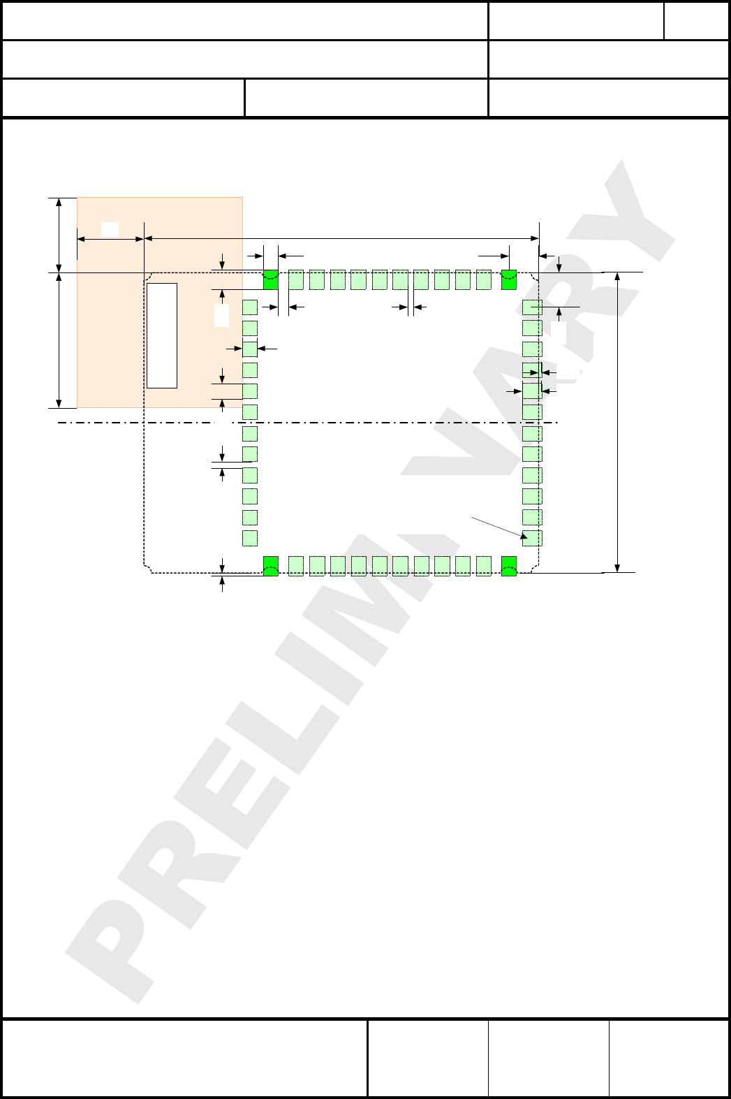
20. RECOMMENDED LAND PATTERN
Empfohlenes Land Pattern
Top View
26,5 mm (Module Lenght)
20,0 mm (Module Width)
Antenna
48 x 1.00
4 x P1 = 0.70 40 x P2 = 0.40
1.00
Pin 1
Sign "1" on the Module
(Bottom Side)
Pad #1
12 x 1.00 x 1.00
2.00
2.30
1.00
0.40 1.30
0.20
Pad #2
36 x 1.00 x 1.30
0.20
1.30
5.0
5.0
Restricted Area
(no ground, no line)
9.0
Dimensions in mm.
The land pattern dimensions above can serve as a guidance, but this information is given
without any legal responsibility.
We recommend the use of the same pad dimensions for the solder paste screen as for the
copper pads, but slight different measures and shapes of the solder paste screen cutouts might
be optimum depending on your soldering process, for example on the chosen solder paste
screen thickness. The solder screen thickness depends on your soldering technology, we
recommend 120µm to 150µm.
IMPORTANT:
The bottom side of PAN4570 is fully coated, nevertheless no copper, such as through hole vias,
planes or tracks on your board component layer should be located below PAN4570 in order to
avoid short cuts. In cases where a track or through hole via has to be located under the module
it has to be kept away from PAN4570 via holes. The PAN4570 multilayer pcb contains a inner rf
shielding ground plane, therefore no pcb copper plane directly below PAN4570 is needed.
If the integrated antenna version of PAN4570 is used, it has to be mounted on a board with a
full copper plane layer of at least 50mm x 50mm, else the radiation performance is degraded.
Place the antenna on the edge of your carrier board and avoid conductive or shielding parts
other than the carrier board in the near of the integrated antenna.

CLASSIFICATION
Einstufung
PRODUCT SPECIFICATION
Produktspezifikation
No.
DS-4570-2400-102
REV.
04
SUBJECT
Thema
MODEM FOR IEEE802.15.4 (ZIGBEE)
“ZigBee” Modem“ (IEEE802.15.4)
PAGE
Seite
19 of 27
CUSTOMER’S CODE
PAN4570
PANASONIC’S CODE
ENWCZA0xyzE
DATE
Datum
31.07.2006
HIGH FREQUENCY PRODUCTS DIVISION
Module Business
PANASONIC ELECTRONIC DEVICES
(EUROPE) GmbH
APPROVED
genehmigt
CHECKED
geprüft
DESIGNED
erstellt
21. SOFTWARE
Software
Software tools
In order to develop code and ZigBeeTM networks the Ember Insight Desktop Development
Environment is required. This environment works with the preceeding EM2420, the EM250 and
the upcoming EM260. For code development it comprises the Integrated Development
Environment (IDE) named xIDE based on eclipse 3.1.0 for editing, compiling and debugging of
C–applications. In addition network visualization and debugging tools are included.
For programming the Ember Insight Adapter is required. This adaptor has to be linked to the
computer where the Ember Insight Desktop is installed on over an Ethernet
network connection. Before connecting PAN4570 to the Ember Insight Adaptor study the latest
Ember Insight Adaptor documentation. The following pins of PAN4570 have to be connected to
the signals on the debug connector of the Ember Insight adaptor:
PAN4570 pin PAN4570 signal name Insight Adapter signal name
various ground ground
1(6) VBAT 3.0Vdc
3 RESET RSTB
25 SIF_CLK SIF_CLK
26 SIF_MISO SIF_MISO
27 SIF_MOSI SIF_MOSI
28 SIF_LOADB SIF_LOADB
as packet trace interface (PTI) also connect the following signals:
10 GPIO4 GPIO4
11 GPIO5 GPIO5
(6) only if the Ember Insight Adaptor is set to powering the target device PAN4570
Ember ZigBeeTM Stack
EmberZNet (currently version 2.2) is the ZigBee stack provided with EM250. It supports as
networking topologies true mesh, star and cluster networks. As ZigBee devices ZigBee
Coordinator, ZigBee Full Fuctional Device and ZigBee End Devices are supported.
For the ease of application programming EmberZNet is controlled by the application over API
commands. Direct ZigBee APS layer APIs are provided for applications that require low level
ZigBee control.
According to [1] each ZigBee device has a unique address. This address is supplied
with PAN4570 in a file containing a table with serial numbers and addresses.

CLASSIFICATION
Einstufung
PRODUCT SPECIFICATION
Produktspezifikation
No.
DS-4570-2400-102
REV.
04
SUBJECT
Thema
MODEM FOR IEEE802.15.4 (ZIGBEE)
“ZigBee” Modem“ (IEEE802.15.4)
PAGE
Seite
20 of 27
CUSTOMER’S CODE
PAN4570
PANASONIC’S CODE
ENWCZA0xyzE
DATE
Datum
31.07.2006
HIGH FREQUENCY PRODUCTS DIVISION
Module Business
PANASONIC ELECTRONIC DEVICES
(EUROPE) GmbH
APPROVED
genehmigt
CHECKED
geprüft
DESIGNED
erstellt
For more information on the items above see the website of Ember Inc. (www.ember.com) and
the documentation included in the Ember Insight Desktop package as part of the Ember
development kits.
22. RELIABILITY TESTS
Zuverlässigkeitstests
The measurement should be done after exposed to room temperature and humidity for
1 hour.
Die Messungen sollten erst nach einer Stunde Lagerung unter normalen Bedingungen erfolgen.
No. Item
Punkt
Limit
Grenzwerte
Condition
Bedingung
1 Vibration test Electrical parameter should be
in specification
a) Freq.:10~50Hz,Amplitude:1.5mm
a) 20min. / cycle,1hrs. each of XYZ axis
b) Freq.:30~100Hz, 6G
b) 20min. / cycle,1hrs. each of XYZ axis
2 Shock test the same as the above Dropped onto hard wood from height of 50cm for
3 times
3 Heat cycle test the same as the above -40°C for 30min. and +85°C for 30min.;
each temperature 300 cycles
4 Moisture test the same as the above +60°C, 90% RH, 300h
5 Low temp. test the same as the above -40°C, 300h
6 High temp. test the same as the above +85°C, 300h
23. PACKAGING
Verpackung
Will be finalized in the next revisions.
24. APPLICATION NOTES
Applikationshinweise
24.1. CAUTIONS FOR SAFETY
Sicherheitshinweise
These specifications are intended to preserve the quality assurance of products as
individual components.
Before use, check and evaluate their operation when mounted on your products. Abide by
these specifications, without deviation when using the products.These products may short-
circuit. If electrical shocks, smoke, fire, and/or accidents involving human life are

CLASSIFICATION
Einstufung
PRODUCT SPECIFICATION
Produktspezifikation
No.
DS-4570-2400-102
REV.
04
SUBJECT
Thema
MODEM FOR IEEE802.15.4 (ZIGBEE)
“ZigBee” Modem“ (IEEE802.15.4)
PAGE
Seite
21 of 27
CUSTOMER’S CODE
PAN4570
PANASONIC’S CODE
ENWCZA0xyzE
DATE
Datum
31.07.2006
HIGH FREQUENCY PRODUCTS DIVISION
Module Business
PANASONIC ELECTRONIC DEVICES
(EUROPE) GmbH
APPROVED
genehmigt
CHECKED
geprüft
DESIGNED
erstellt
anticipated when a short circuit occurs, then at least, provide the following failsafe
functions, as a minimum.
(1) Ensure the safety of the whole system by installing a protection circuit and a protection
device.
(2) Ensure the safety of the whole system by installing a redundant circuit or another system
to prevent a single fault causing an unsafe status.
24.2. DESIGN ENGINEERING NOTES
Designhinweise
Heat is the major cause of shortening the life of these products. Avoid assembly and use
of the target equipment in conditions where the products' temperature may exceed the
maximum allowable.
Failure to do so may result in degrading of the product’s functions and damage to the
product.
If pulses or other transient loads (a large load applied in a short time) are applied to the
products, then before use, check and evaluate their operation when assembled on your
products.
Carefully position the products so that their heat will not burn into printed circuit boards or
affect the other components that are susceptible to heat.
Carefully locate these products so that their temperatures will not increase due to the
effects of heat generated by neighboring components.
If a vinyl-covered wire comes into contact with the products, then the cover will melt and
generate toxic gas, damaging the insulation. Never allow contact between the cover and
these products to occur.
These products are intended for general purpose and standard use in general electronic
equipment, such as home appliances, office equipment, information and communication
equipment.
These products are not intended for other uses, other than under the special conditions
shown below. Before using these products under such special conditions, check their
performance and reliability under the said special conditions carefully to determine
whether or not they can be used in such a manner.
(1) In liquid, such as water, salt water, oil, alkali, or organic solvent, or in places where liquid
may splash.
(2) In direct sunlight, outdoors, or in a dusty environment
(3) In an environment where condensation occurs.
(4) In an environment with a high concentration of harmful gas (e.g. salty air, HCl, Cl2, SO2,
H2S, NH3, and NOx)
If an abnormal voltage is applied due to a problem occurring in other components or
circuits, replace these products with new products because they may not be able to
provide normal performance even if their electronic characteristics and appearances
appear satisfactory.
Mechanic stress during assembly on board and operation has to be avoived.
Pressing on parts of the metal cover or fastening objects to the metal cover is not allowed.
CLASSIFICATION
Einstufung
PRODUCT SPECIFICATION
Produktspezifikation
No.
DS-4570-2400-102
REV.
04
SUBJECT
Thema
MODEM FOR IEEE802.15.4 (ZIGBEE)
“ZigBee” Modem“ (IEEE802.15.4)
PAGE
Seite
22 of 27
CUSTOMER’S CODE
PAN4570
PANASONIC’S CODE
ENWCZA0xyzE
DATE
Datum
31.07.2006
HIGH FREQUENCY PRODUCTS DIVISION
Module Business
PANASONIC ELECTRONIC DEVICES
(EUROPE) GmbH
APPROVED
genehmigt
CHECKED
geprüft
DESIGNED
erstellt
24.3. STORAGE CONDITIONS
Lagerbedingungen
The module may not be stressed mechanically during storage.
Do not store these products in the following conditions or the performance characteristics
of the product, such as RF performance will be adversely affected:
(1) Storage in salty air or in an environment with a high concentration of corrosive gas, such
as Cl2, H2S, NH3, SO2, or NOX
(2) Storage in direct sunlight
(3) Storage in an environment where the temperature may be outside the range of 5°C to
35°C range, or where the humidity may be outside the 45 to 85% range.
(4) Storage of the products for more than one year after the date of delivery at your company
if all the above conditions (1) to (3) have been avoided.
25. ORDERING INFORMATION
Ordering part number Description MOQ(7)
ENWCZA02A3E (8)
Engineering Sample PAN4570
PAN4570 with integrated ceramic antenna (U.FL socket will not be
mounted, when the module is in mass production)
1
ENWCZA03N2E (8)
Engineering Sample PAN4570
PAN4570 with U.FL male socket (ceramic antenna will not be
mounted, when the module is in mass production)
1
ENWCZA04N4E (8)
Engineering Sample PAN4570
PAN4570 with RF out on a SMD pad (U.FL plug and ceramic
antenna will not be mounted, when the module is in mass
production)
1
Notes:
(7) Abbreviation for Minimum Order Quantity (MOQ)
(8) As long as the module has engineering status, the sign ES are available on the label.
The “Z” in the ordering part number indicates the engineering sample status. After mass production
the “Z” will be changed to the “9” and the ES sign on the label will be deleted.

CLASSIFICATION
Einstufung
PRODUCT SPECIFICATION
Produktspezifikation
No.
DS-4570-2400-102
REV.
04
SUBJECT
Thema
MODEM FOR IEEE802.15.4 (ZIGBEE)
“ZigBee” Modem“ (IEEE802.15.4)
PAGE
Seite
23 of 27
CUSTOMER’S CODE
PAN4570
PANASONIC’S CODE
ENWCZA0xyzE
DATE
Datum
31.07.2006
HIGH FREQUENCY PRODUCTS DIVISION
Module Business
PANASONIC ELECTRONIC DEVICES
(EUROPE) GmbH
APPROVED
genehmigt
CHECKED
geprüft
DESIGNED
erstellt
26. ROHS DECLARATION
RoHS-Erklärung
Declaration of environmental compatibility for supplied products:
Hereby we declare to our best present knowledge based on declaration of our suppliers that this
product do not contain by now the following substances which are banned by Directive
2002/95/EC (RoHS) or if contain a maximum concentration of 0,1% by weight in homogeneous
materials for
• Lead and lead compounds
• Mercury and mercury compounds
• Chromium (VI)
• PBB (polybrominated biphenyl) category
• PBDE (polybrominated biphenyl ether) category
And a maximum concentration of 0,01% by weight in homogeneous materials for
• Cadmium and cadmium compounds
27. DATA SHEET STATUS
Datenblatt Status
This data sheet contains data from the PRELIMINARY specification. Supplementary data will be
published at a later date. Panasonic Electronic Devices (Europe) GmbH reserves the right to
change the specification without notice, in order to improve the design and supply the best
possible product.
Please consult the most recently issued data sheet before initiating or completing a design.
CLASSIFICATION
Einstufung
PRODUCT SPECIFICATION
Produktspezifikation
No.
DS-4570-2400-102
REV.
04
SUBJECT
Thema
MODEM FOR IEEE802.15.4 (ZIGBEE)
“ZigBee” Modem“ (IEEE802.15.4)
PAGE
Seite
24 of 27
CUSTOMER’S CODE
PAN4570
PANASONIC’S CODE
ENWCZA0xyzE
DATE
Datum
31.07.2006
HIGH FREQUENCY PRODUCTS DIVISION
Module Business
PANASONIC ELECTRONIC DEVICES
(EUROPE) GmbH
APPROVED
genehmigt
CHECKED
geprüft
DESIGNED
erstellt
28. REGULATORY INFORMATION
28.1. FCC NOTICE
The device PAN4570, including the ceramic antenna (ENWC9A02A3E) complies with Part
15 of the FCC Rules. The device meets the requirements for modular transmitter approval
as detailed in FCC public Notice DA00-1407.transmitter
Operation is subject to the following two conditions: (1) This device may not cause harmful
interference, and (2) This device must accept any interference received, including
interference that may cause undesired operation.
28.2. CAUTION
The FCC requires the user to be notified that any changes or modifications made to this
device that are not expressly approved by Panasonic Electronic Devices Europe GmbH
may void the user's authority to operate the equipment.
This equipment has been tested and found to comply with the limits for a Class B digital
device, pursuant to Part 15 of the FCC Rules. These limits are designed to provide
reasonable protection against harmful interference in a residential installation. This
equipment generates, uses and can radiate radio frequency energy and, if not installed
and used in accordance with the instructions, may cause harmful interference to radio
communications. However, there is no guarantee that interference will not occur in a
particular installation. If this equipment does cause harmful interference to radio or
television reception, which can be determined by turning the equipment off and on, the
user is encouraged to try to correct the interference by one or more of the following
measures:
• Reorient or relocate the receiving antenna.
• Increase the separation between the equipment and receiver.
• Connect the equipment into an outlet on a circuit different from that to which the
receiver is connected.
• Consult the dealer or an experienced radio/TV technician for help
28.3. LABELING REQUIREMENTS
The Original Equipment Manufacturer (OEM) must ensure that FCC labeling requirements
are met. This includes a clearly visible label on the outside of the OEM enclosure
specifying the appropriate Panasonic FCC identifier for this product as well as the FCC
Notice above. The FCC identifier are FCCID: T7VEM250A. This FCC identifier is only
valid for the part number ENWC9A02A3E (PAN4570 with mounted ceramic antenna). For
details, please see the chapter 25. Ordering Information.
The EUT is labelled with FCC ID: T7VEM250A. This Label must be visible for the user in
the end product. If the module is inside of an end product, the label will not be visible. In
this case the end product will be labelled exterior with "Contains FCC ID: T7VEM250A"
CLASSIFICATION
Einstufung
PRODUCT SPECIFICATION
Produktspezifikation
No.
DS-4570-2400-102
REV.
04
SUBJECT
Thema
MODEM FOR IEEE802.15.4 (ZIGBEE)
“ZigBee” Modem“ (IEEE802.15.4)
PAGE
Seite
25 of 27
CUSTOMER’S CODE
PAN4570
PANASONIC’S CODE
ENWCZA0xyzE
DATE
Datum
31.07.2006
HIGH FREQUENCY PRODUCTS DIVISION
Module Business
PANASONIC ELECTRONIC DEVICES
(EUROPE) GmbH
APPROVED
genehmigt
CHECKED
geprüft
DESIGNED
erstellt
28.4. ANTENNA WARNING
The related part number for this device is ENWC9A03N2E (PAN4570 with mounted
connector). For details, please see the chapter 25. Ordering Information. This device will
be tested with an UFL connector from company Hirose and with the antennas listed below.
When integrated in the OEMs product, these fixed antennas require installation preventing
end-users from replacing them with non-approved antennas. Any antenna not in the
following table must be tested to comply with FCC Section 15.203 for unique antenna
connectors and Section 15.247 for emissions. The FCC identifier for this device will be
available, after a first measurement with an approved antenna.
28.5. APPROVED ANTENNA LIST
Note: We are able to qualify your antenna and will add to this list as that process is completed.
Item Part Number Manufacturer Frequency Band Type Gain (dBi)
1
2
28.6. RF EXPOSURE PAN4570
To comply with FCC RF Exposure requirements, the Original Equipment Manufacturer
(OEM) must ensure that the approved antenna in the previous table must be installed
and/or configured to operate with a separation distance of 2.5cm or more from all persons
to satisfy RF Exposure compliance.
The preceding statement must be included as a CAUTION statement in manuals for
products operating with the approved antennas in the previous table to alert users on FCC
RF Exposure compliance.
Any notification to the end user of installation or removal instructions about the integrated
radio module is not allowed.
The radiated output power of PAN4570 with mounted ceramic antenna
(FCC ID: T7VEM250A) is far below the FCC radio frequency exposure limits.
Nevertheless, the PAN4570 shall be used in such a manner that the potential for human
contact during normal operation is minimized.
The EUT meets the requirements of FCC section 15.249, even if the EUT transmitted at
the maximum allowed field strength (50,000 uV/m),which the equivalent e.i.r.p would be
0.75 mW. End users may not be provided with the module installation instructions. OEM
integrators and end users must be provided with transmitter operating conditions for
satisfying RF exposure compliance.

CLASSIFICATION
Einstufung
PRODUCT SPECIFICATION
Produktspezifikation
No.
DS-4570-2400-102
REV.
04
SUBJECT
Thema
MODEM FOR IEEE802.15.4 (ZIGBEE)
“ZigBee” Modem“ (IEEE802.15.4)
PAGE
Seite
26 of 27
CUSTOMER’S CODE
PAN4570
PANASONIC’S CODE
ENWCZA0xyzE
DATE
Datum
31.07.2006
HIGH FREQUENCY PRODUCTS DIVISION
Module Business
PANASONIC ELECTRONIC DEVICES
(EUROPE) GmbH
APPROVED
genehmigt
CHECKED
geprüft
DESIGNED
erstellt
29. RELATED DOCUMENTS
Mitgeltende Dokumente
[1] IEEE Standard 802.15.4 –2003 Wireless Medium Access Control (MAC) and Physical Layer
(PHY) Specifications for Low-Rate Wireless Personal Area Networks (LR-WPANs)
[2] Data Sheet EM250, Ember Inc. (www.ember.com)
[3] Data Sheet U.FL-Series 2004.2 Hirose
Ultra Small Surface Mount Coaxial Connectors - Low Profile 1.9mm or 2.4mm Mated Height

CLASSIFICATION
Einstufung
PRODUCT SPECIFICATION
Produktspezifikation
No.
DS-4570-2400-102
REV.
04
SUBJECT
Thema
MODEM FOR IEEE802.15.4 (ZIGBEE)
“ZigBee” Modem“ (IEEE802.15.4)
PAGE
Seite
27 of 27
CUSTOMER’S CODE
PAN4570
PANASONIC’S CODE
ENWCZA0xyzE
DATE
Datum
31.07.2006
HIGH FREQUENCY PRODUCTS DIVISION
Module Business
PANASONIC ELECTRONIC DEVICES
(EUROPE) GmbH
APPROVED
genehmigt
CHECKED
geprüft
DESIGNED
erstellt
30. GENERAL INFORMATION
Allgemeine Informationen
© Panasonic Electronic Devices (Europe) GmbH 2006.
All rights reserved.
This product description does not lodge the claim to be complete and free of mistakes.
Please contact the related product manager in every case.
If we deliver samples to the customer, these samples have the status Engineering Samples.
This means, the design of this product is not yet concluded. Engineering Samples may be
partially or fully functional, and there may be differences to be published Data Sheet.
Engineering Samples are not qualified and are not to be used for reliability testing or series
production.
Disclaimer:
Customer acknowledges that samples may deviate from the Data Sheet and may bear defects
due to their status of development and the lack of qualification mentioned above.
Panasonic Electronic Devices (Europe) GmbH rejects any liability or product warranty for
Engineering Samples. In particular, Panasonic Electronic Devices (Europe) GmbH disclaims
liability for damages caused by
• the use of the Engineering Sample other than for Evaluation Purposes, particularly the
installation or integration in an other product to be sold by Customer,
• deviation or lapse in function of Engineering Sample,
• improper use of Engineering Samples.
Panasonic Electronic Devices (Europe) GmbH disclaimes any liability for consequential and
incidental damages. In case of any questions, please contact your local sales partner or the
related product manager.
31. LIFE SUPPORT POLICY
Politik für Lebenserhaltungssysteme
This Panasonic Electronic Devices (Europe) GmbH product is not designed for use in life
support appliances, devices, or systems where malfunction can reasonably be expected to
result in a significant personal injury to the user, or as a critical component in any life support
device or system whose failure to perform can be reasonably expected to cause the failure of
the life support device or system, or to affect its safety or effectiveness. Customers using or
selling these products for use in such applications do so at their own risk and agree to fully
indemnify Panasonic Electronic Devices (Europe) GmbH for any damages resulting.