Panasonic Devices Europe EM250B ETRX2-PA, STRX2-PA, ETRX2HR-PA, STRX2HR-PA User Manual 1
Panasonic Industrial Devices Europe GmbH ETRX2-PA, STRX2-PA, ETRX2HR-PA, STRX2HR-PA 1
UserManual.wiki
>
Panasonic Devices Europe
>
EM250B User Manual
Manual
Navigation menu
Upload a User Manual
Namespaces
Wiki Guide
HTML
PDF
Info
Views
User Manual
Discussion / Help
Navigation
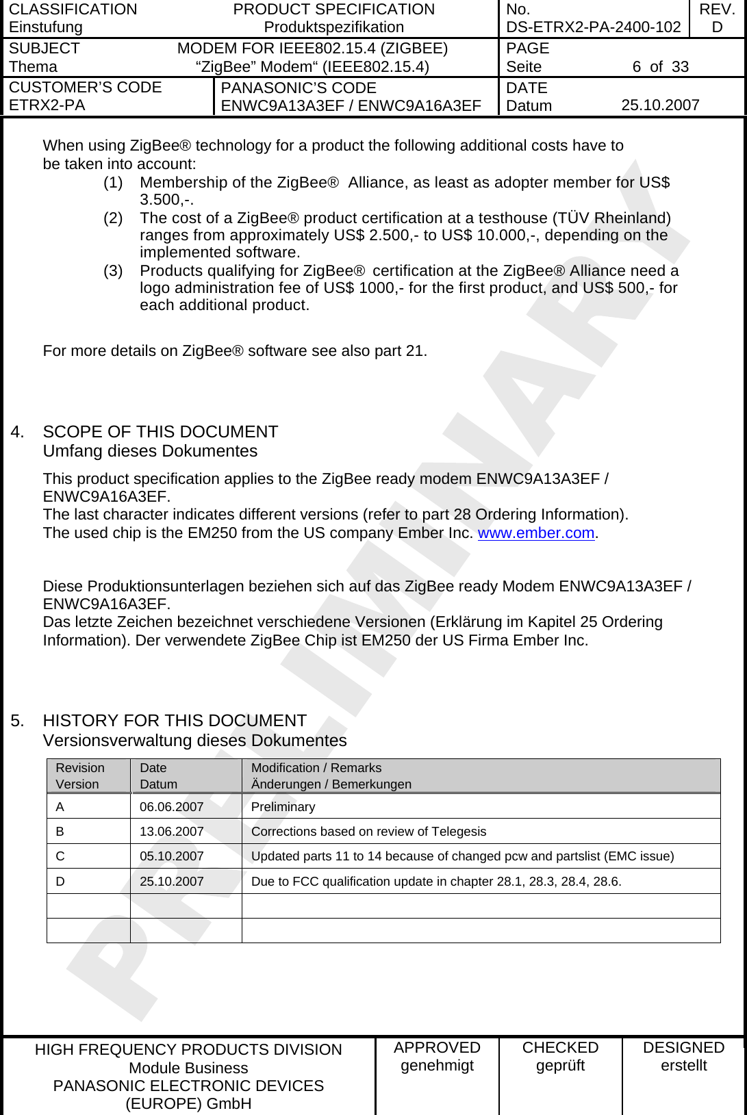
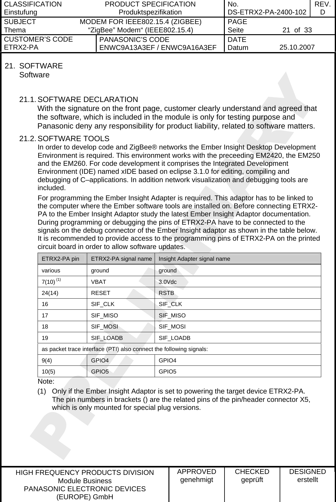
![CLASSIFICATION Einstufung PRODUCT SPECIFICATION Produktspezifikation No. DS-ETRX2-PA-2400-102 REV.D SUBJECT Thema MODEM FOR IEEE802.15.4 (ZIGBEE) “ZigBee” Modem“ (IEEE802.15.4) PAGE Seite 4 of 33 CUSTOMER’S CODE ETRX2-PA PANASONIC’S CODE ENWC9A13A3EF / ENWC9A16A3EF DATE Datum 25.10.2007 HIGH FREQUENCY PRODUCTS DIVISION Module Business PANASONIC ELECTRONIC DEVICES (EUROPE) GmbH APPROVED genehmigt CHECKED geprüft DESIGNED erstellt 1. KEY FEATURES Schlüsseleigenschaften • short range 2,4GHz ISM band IEEE802.15.4 [1] compliant transceiver • Complete system based on the ZigBee ® compliant platform EM250 that combines the transceiver with a powerful, efficient industry proven 16-bit microprocessor with comprehensive hardware supported network-level debugging features • designed specifically for use with EmberZNet, Embers ZigBee® compliant embedded mesh networking • powerful 16-bit microprocessor • 128k flash ROM and 5k of SRAM memory • high Rx sensitivity of –97dBm at 1% Packet Error Rate • increased Tx output power setting range from -20dBm to +17dBm • Small size 20,5mm x 37,5mm x 2.8mm • single port antenna terminal (pcb pad, U.FL socket or chip antenna versions available) • Integrated ADC module with 12-bit resolution • two 16-bit general purpose timers; one 16-bit sleep timer • 17 GPIO pins with alternate functions • two sleep modes for increased battery life • low voltage detect/reset • complies with ETSI EN300328 and FCC part15 2. APPLICATIONS FOR THE MODULE Anwendungen für das Modul • ZigBee® Coordinators,Routers and End Devices working in star and mesh networks • Wireless sensor and actuator networks • Remote control and wire replacement in industrial systems • Building automation and control • Inventory and logistics management • HID (Human Interface Devices) • Toys • Home gateways](https://usermanual.wiki/Panasonic-Devices-Europe/EM250B/User-Guide-860168-Page-4.png)
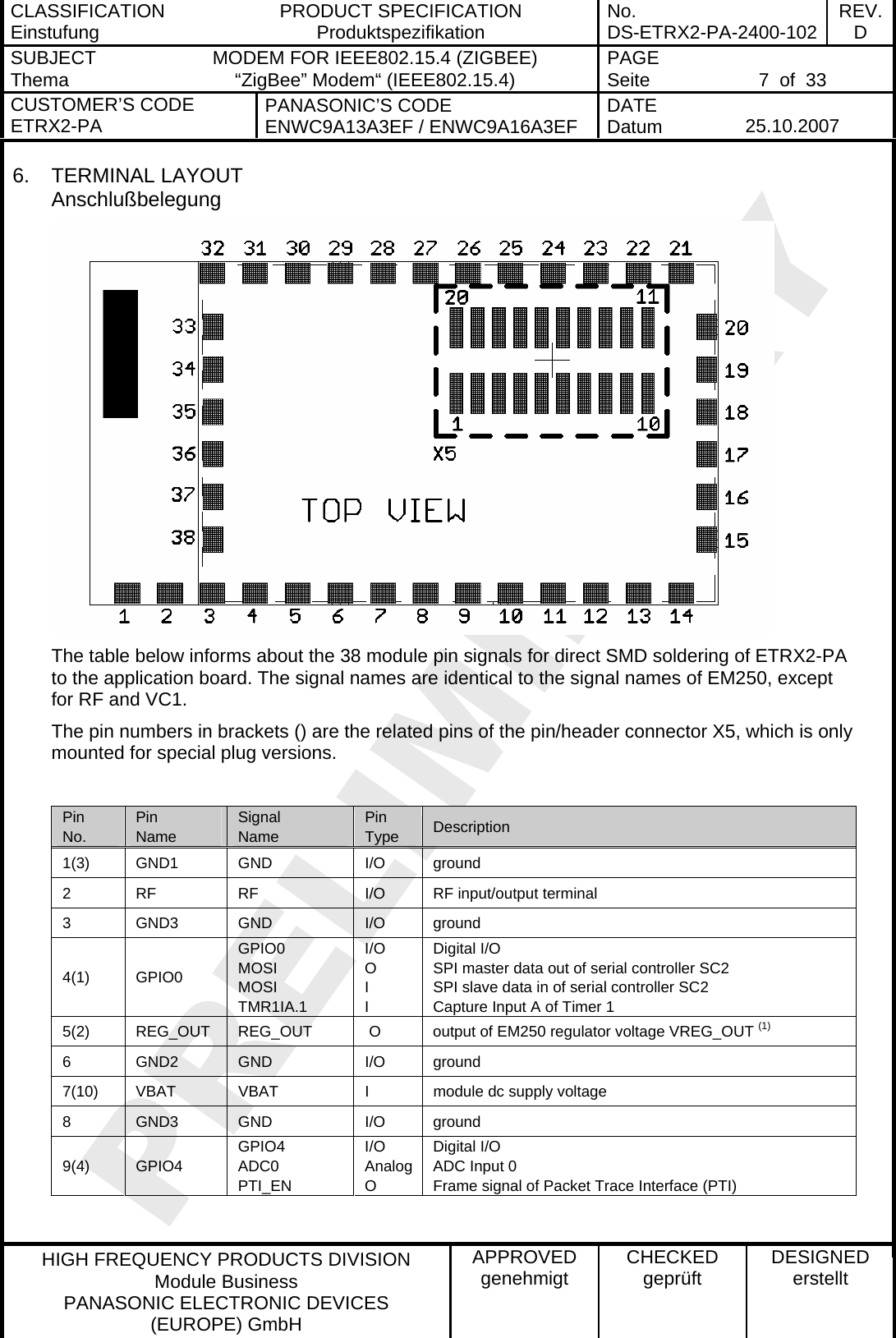
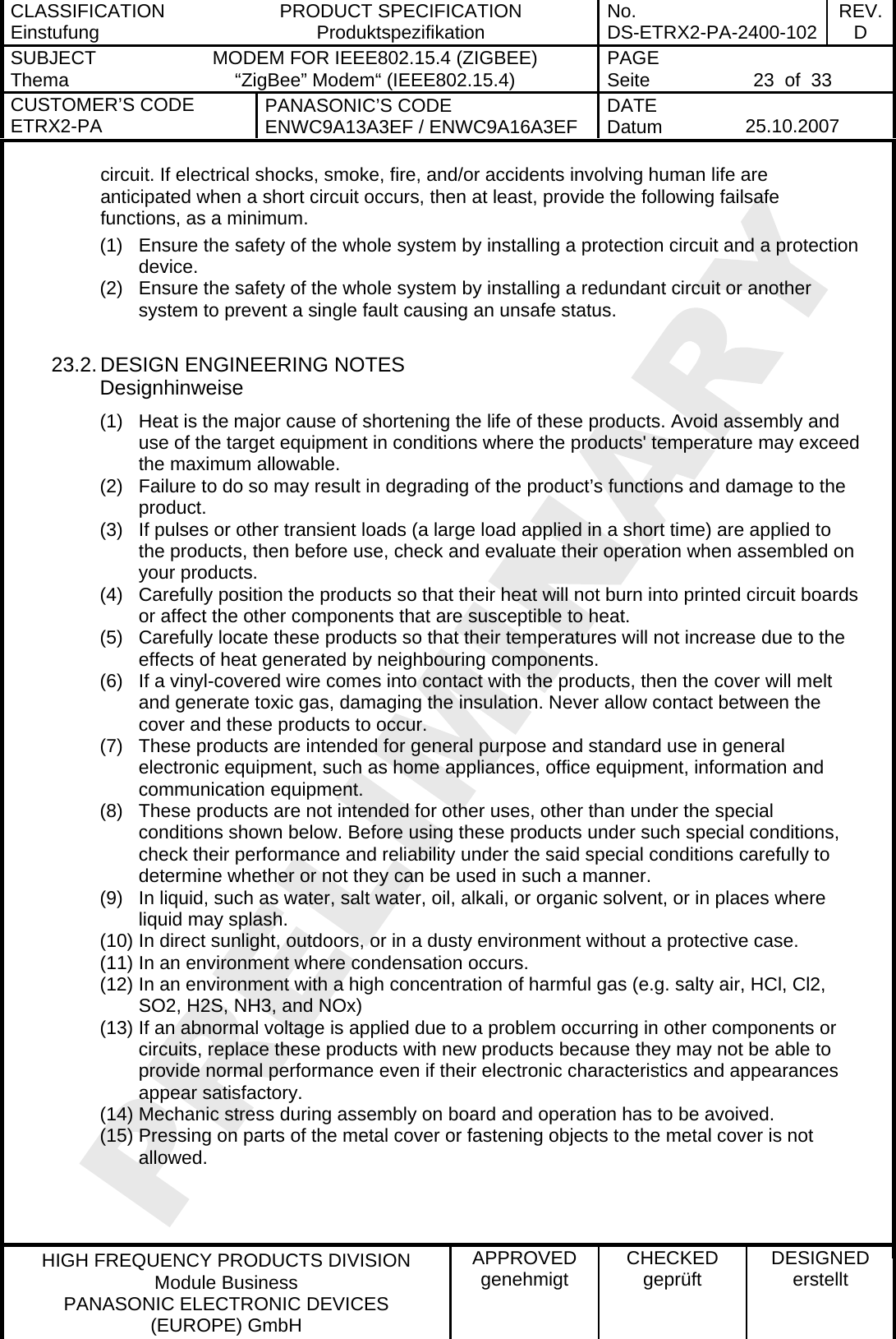
![CLASSIFICATION Einstufung PRODUCT SPECIFICATION Produktspezifikation No. DS-ETRX2-PA-2400-102 REV.D SUBJECT Thema MODEM FOR IEEE802.15.4 (ZIGBEE) “ZigBee” Modem“ (IEEE802.15.4) PAGE Seite 5 of 33 CUSTOMER’S CODE ETRX2-PA PANASONIC’S CODE ENWC9A13A3EF / ENWC9A16A3EF DATE Datum 25.10.2007 HIGH FREQUENCY PRODUCTS DIVISION Module Business PANASONIC ELECTRONIC DEVICES (EUROPE) GmbH APPROVED genehmigt CHECKED geprüft DESIGNED erstellt 3. DESCRIPTION OF THE MODULE Beschreibung des Moduls ETRX2-PA contains the single chip EM250 [2] from Ember Inc., a 24MHz reference crystal and RF frontend circuitry optimized for best RF performance. As single ended RF output the module is available with integrated antenna or 50ohms or U.FL male socket [3] or 50 ohms pad terminal on the bottom of the module. Compared to ETRX2 the ETRX2-PA module allows extended range of operation by means of an integrated high efficieny power amplifier inserted in the Tx path. A low loss LTCC bandpassfilter for the 2,4GHz I.S.M. band has an effect on both Tx and Rx path. As a result for Rx mode the immunity against interferers (for example operating at 1,8 GHz) is improved compared to ETRX2. Two additional hardware options are available on request: 3.1. ON BOARD DC REGULATOR Although the EM250 already contains a dc regulator internally, the module can be requested with an extra integrated onboard dc regulator. Some applications could benefit from this additional regulator because as of for example: (1) Further extension of the input voltage range or (2) Extented battery life by replacing the regulator within EM250 by a special ultra low quiescent current regulator or (3) allowing for operation on very noisy power supplies Two different types of regulators can be chosen, a linear low dropout (LDO) type or a high efficiency switched buck regulator. Depending on the power supply conditions of the application the optimum regulator can be selected on demand. 3.2. ON BOARD REFERENCE CRYSTAL A second option that is available is an on board 32,768kHz crystal reference. This option is provided for applications that require a precision reference clock. Please contact the manufacturer if one of the options could be useful for your product design. ETRX2-PA is used for ZigBee® (www.zigbee.org) applications working with EmberZNetTM of Ember Inc. (www.ember.com). EmberZNetTM is a fully ZigBee® compliant networking stack. For code development Insight DesktopTM, a comprehensive integrated development environment (IDE) and C-language compiler toolchain from Ember Inc. is required. Insight DesktopTM is part of Ember development kits and can currently be purchased together with programming adaptors as EM250 jumpstart kit at a price of USD 2500,- directly from Ember Inc. (www.ember.com).](https://usermanual.wiki/Panasonic-Devices-Europe/EM250B/User-Guide-860168-Page-5.png)
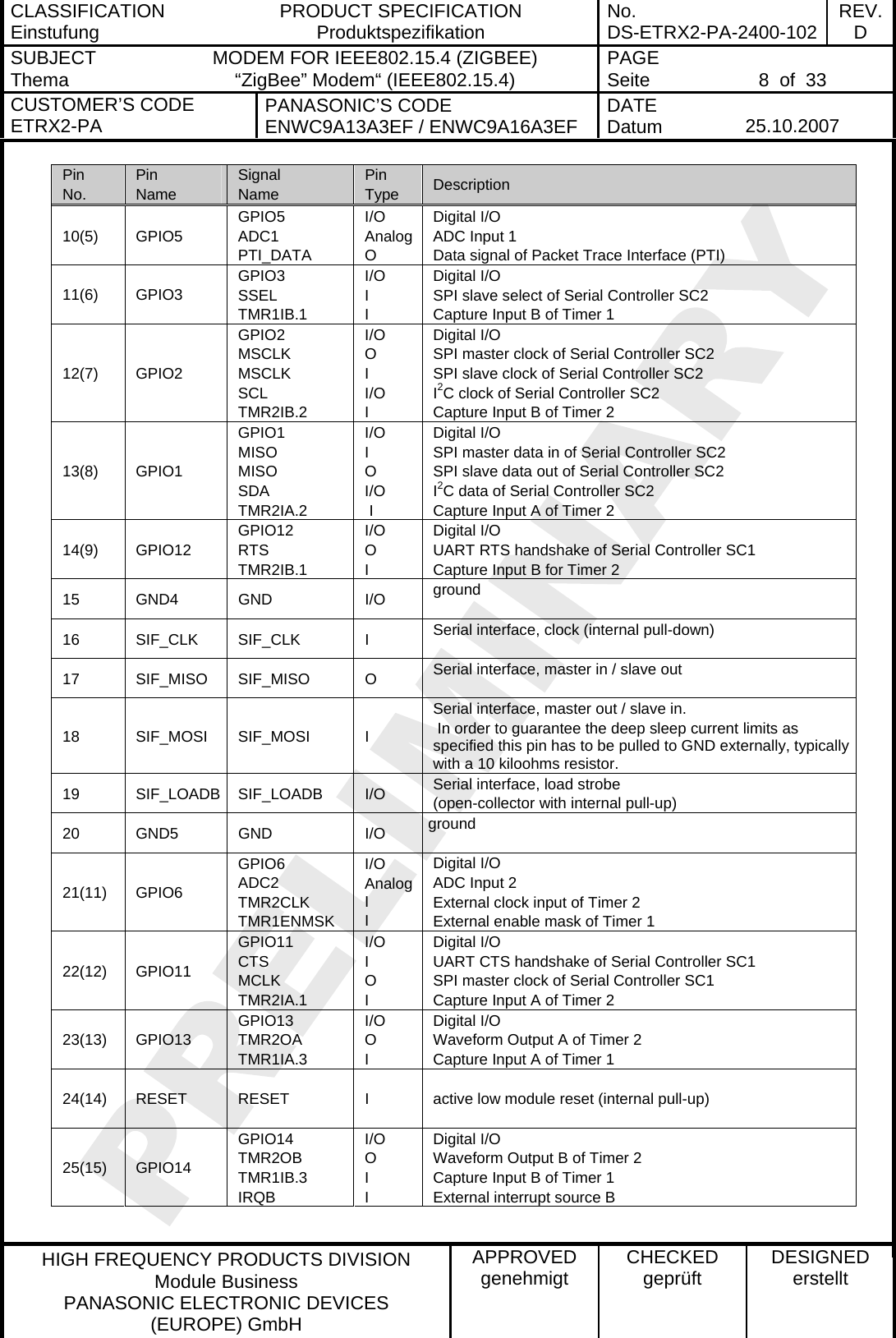
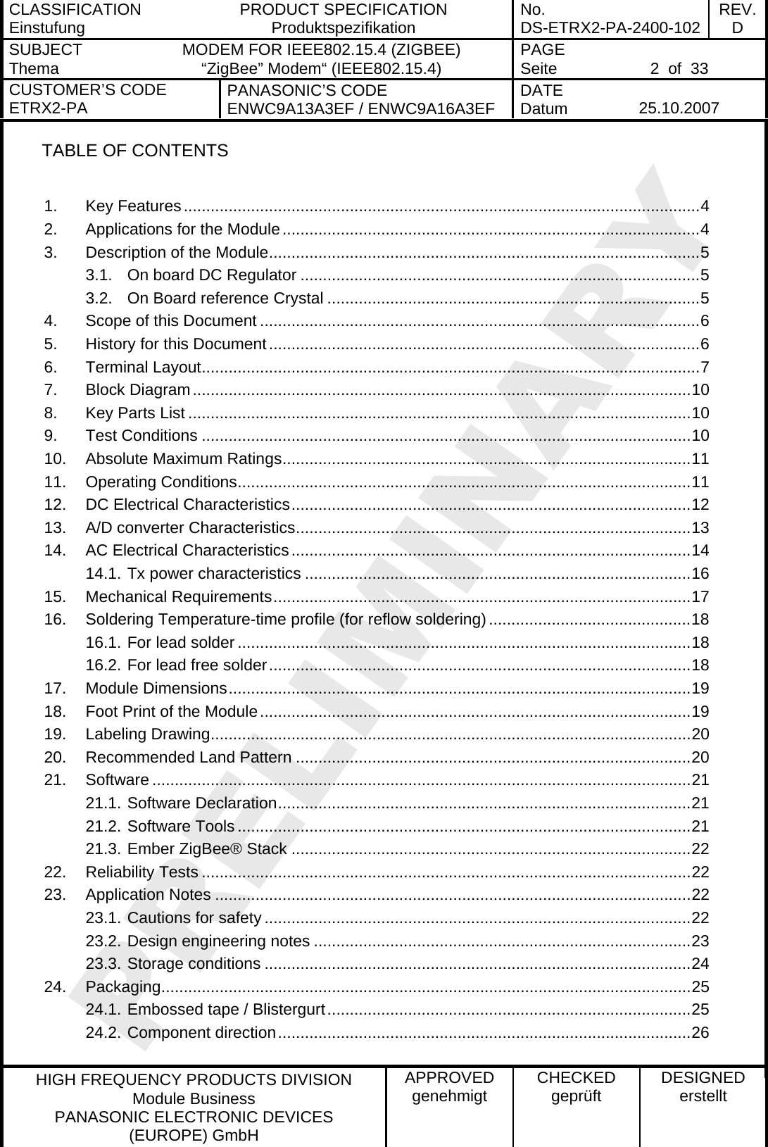
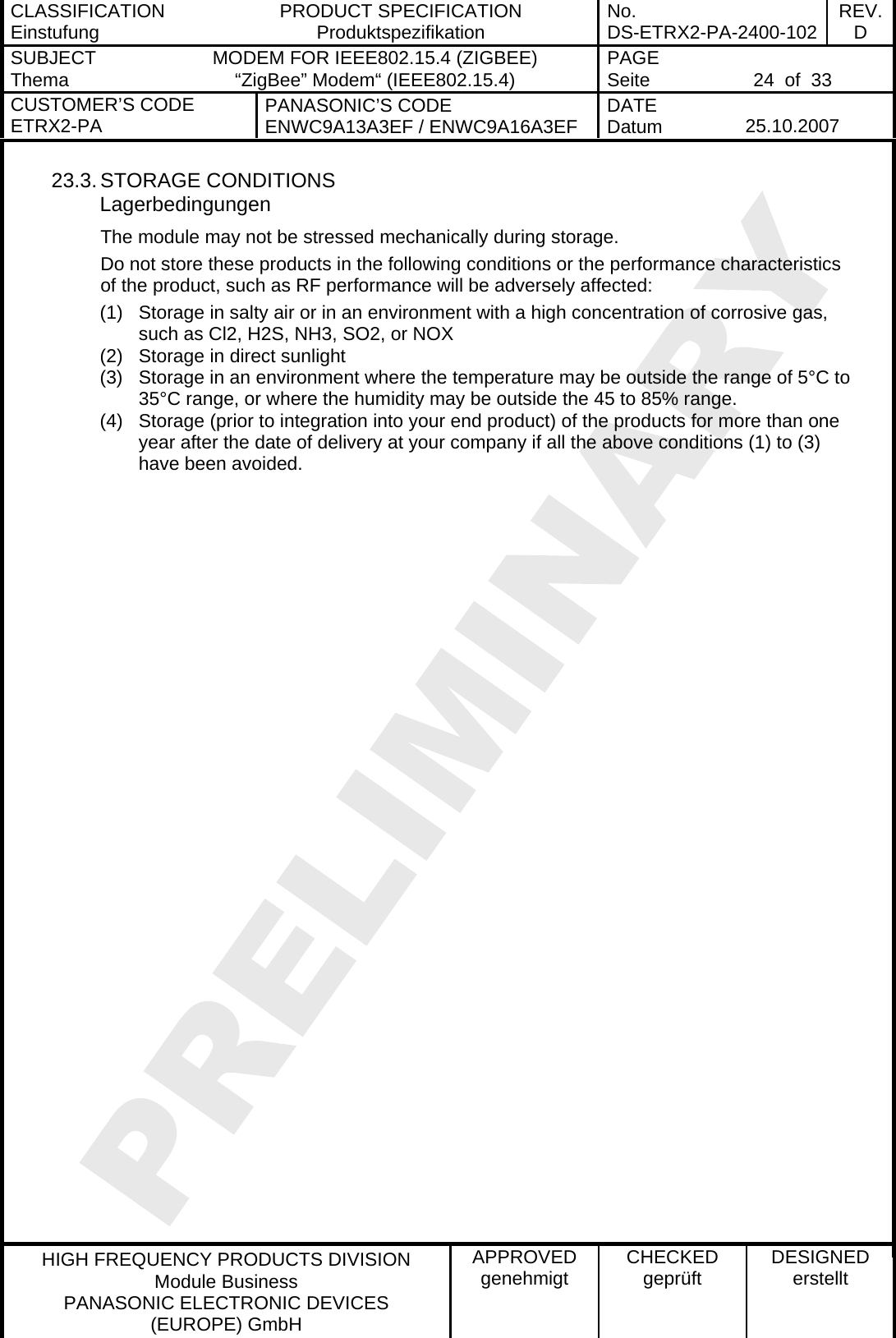
![CLASSIFICATION Einstufung PRODUCT SPECIFICATION Produktspezifikation No. DS-ETRX2-PA-2400-102 REV.D SUBJECT Thema MODEM FOR IEEE802.15.4 (ZIGBEE) “ZigBee” Modem“ (IEEE802.15.4) PAGE Seite 10 of 33 CUSTOMER’S CODE ETRX2-PA PANASONIC’S CODE ENWC9A13A3EF / ENWC9A16A3EF DATE Datum 25.10.2007 HIGH FREQUENCY PRODUCTS DIVISION Module Business PANASONIC ELECTRONIC DEVICES (EUROPE) GmbH APPROVED genehmigt CHECKED geprüft DESIGNED erstellt 7. BLOCK DIAGRAM Blockdiagramm 24MHz 32,768kHz(optional)EM250RF transceiver 2,4GHz16-bit XAP2b uC128kB flash / 5k RAMGPIO0 GPIO16 I / Oprogramming4 SIF LDO or DC converter (optional) VBATVBAT VREG RESET RESETBALUNintegrated antenna pad U.FL socket rf terminal selection, filtering and matching circuitry LDO 1,8VdcTxRxBALUNRx/Tx switch PA 8. KEY PARTS LIST Liste der Schlüsselkomponenten Part Name Teilenummer Material Material P.W.Board Leiterplatte Glass cloth epoxide resin with gold plating FR4 mit Goldauflage Casing Deckel Material: CuNi18ZN20, thickness 0.2mm Material: Weißblech 0,2mm Dicke RF-IC part name RF IC Name EM250 from Ember Inc.(www.ember.com)All information are based on [2] chapter 28. 9. TEST CONDITIONS Meßbedingungen Measurements shall be made under room temperature and humidity unless otherwise specified. Messungen unter normalen Bedingungen, Abweichungen sind gesondert notiert. Temperature 25 ± 10°C Humidity 40 to 85%RH Temperatur 25 ± 10°C Luftfeuchtigkeit 40 to 85%RH](https://usermanual.wiki/Panasonic-Devices-Europe/EM250B/User-Guide-860168-Page-10.png)
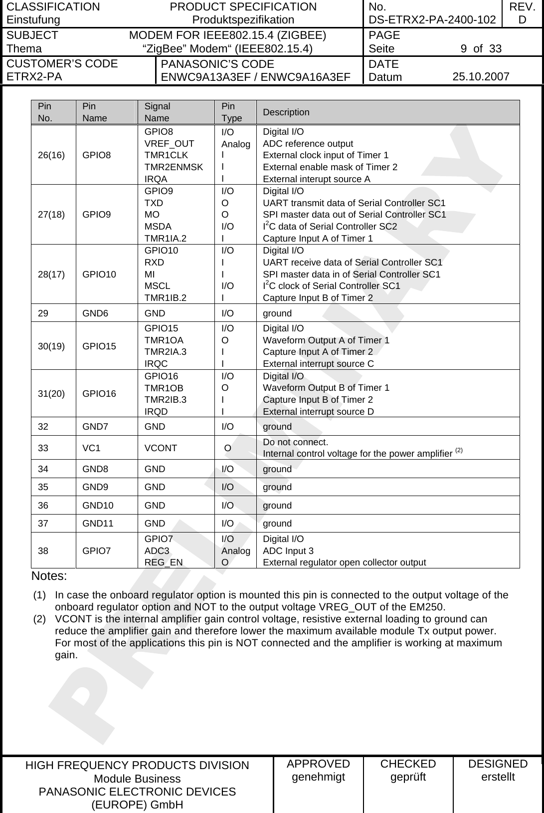
![CLASSIFICATION Einstufung PRODUCT SPECIFICATION Produktspezifikation No. DS-ETRX2-PA-2400-102 REV.D SUBJECT Thema MODEM FOR IEEE802.15.4 (ZIGBEE) “ZigBee” Modem“ (IEEE802.15.4) PAGE Seite 11 of 33 CUSTOMER’S CODE ETRX2-PA PANASONIC’S CODE ENWC9A13A3EF / ENWC9A16A3EF DATE Datum 25.10.2007 HIGH FREQUENCY PRODUCTS DIVISION Module Business PANASONIC ELECTRONIC DEVICES (EUROPE) GmbH APPROVED genehmigt CHECKED geprüft DESIGNED erstellt 10. ABSOLUTE MAXIMUM RATINGS Absolute Grenzwerte The maximum ratings may not be exceeded under any circumstances, not even momentarily and individually, as permanent damage to the module will result. No. Item Punkt Symbol Zeichen Absolute Maximum Ratings Absolute Grenzwerte Unit Einheit 1 Supply voltage VBAT -0.1 to +3.5 Vdc 2 Voltage on any GPIO[16:0] , SIF_CLK, SIF_MISO, SIF_MOSI, SIF_LOADB, OSC32A, OSC32B, RESET, REG_OUT Vin -0.3 to VBAT+0.3 Vdc 3 Storage temperature range Tstg -40 to +105 °C 4 Operating temperature range Top -40 to +85 °C 5 Input RF level Pmax 0 dBm 6 ESD on any pin (1) according to Human Body Model (HBM) circuit description VTHHBM ±2 kV 7 Lead temperature Löttemperatur TDeath T.B.D. °C Notes: (1) Input must be current limited to the value specified. 11. OPERATING CONDITIONS Betriebsbedingungen VBAT = 3.3V, Tamb = 25°C , NORMAL MODE if nothing else stated No. Item Condition / Remark Symbol Value Unit Min Typ Max 1 Supply voltage The typical value is recommended VDD 2.7 3.3 3.5 Vdc 2 RF Input Frequency fC2405 2480 MHz 3 RF Input Power pIN 0 dBm 4 EM250 Tx power mode setting NORMAL MODE or BOOST MODE(1) and external PA 5 EM250 Tx output power setting Channels 1-14 pOUTSET -43 +3 dBm 6 EM250 Tx output power setting(2) Channel 0 pOUTSET -43 -3 dBm 7 EM250 Tx output power setting(2) Channel 15 pOUTSET -43 -14 dBm 8 To 5. corresponding typical module output power. For more details see part 14. Channels 1-14 NORMAL MODE BOOST MODE pOUT -22 -21 +17,5 +18,5 dBm dBm 9 Allowed Tx duty cycle Maximum output power set and 0dBi 10 %](https://usermanual.wiki/Panasonic-Devices-Europe/EM250B/User-Guide-860168-Page-11.png)
![CLASSIFICATION Einstufung PRODUCT SPECIFICATION Produktspezifikation No. DS-ETRX2-PA-2400-102 REV.D SUBJECT Thema MODEM FOR IEEE802.15.4 (ZIGBEE) “ZigBee” Modem“ (IEEE802.15.4) PAGE Seite 12 of 33 CUSTOMER’S CODE ETRX2-PA PANASONIC’S CODE ENWC9A13A3EF / ENWC9A16A3EF DATE Datum 25.10.2007 HIGH FREQUENCY PRODUCTS DIVISION Module Business PANASONIC ELECTRONIC DEVICES (EUROPE) GmbH APPROVED genehmigt CHECKED geprüft DESIGNED erstellt No. Item Condition / Remark Symbol Value Unit Min Typ Max Antenna (3)10 Logic Input Voltage Low pOUTT 0 0.2x VBAT V 11 Logic Input Voltage High VIH 0.8x VBAT VBAT V 12 SPI clock rate The typical value is recommended fSPI 12 MHz 13 Operating temperature range Top -40 +85 °C Notes: ETRX2-PA is designed to comply to the standards and regulations listed in part 29. The conditions for compliance are: BOOST MODE is allowed with some restrictions : In order to stay within the output power limits 20dBm (EN300 328) and -30dBm PSD mask absolute (IEEE802.15.4) the power setting value is limited to 0dBm maximum for supply voltages above 3,3Vdc or operating temperatures below 0°C. (1) On the lowest channel 0 (2405MHz) and the highest channel 15 (2480MHz) the maximum allowed output power settings are limited to the maximum values stated above in order to not exceed the the spectral power density limits at the 2,4GHz I.S.M. band edges under extreme conditions as stated in part 4.3.3 “Frequency Range” of [1] (2) With these settings and duty cycles below 10% the limits for “Maximum Spectral Output Power density” according to part 4.3.2 of [1] are not exceeded. For lower antenna gain and/or lower Tx output power the duty cycle may be increased according to the formula in [1]. 12. DC ELECTRICAL CHARACTERISTICS conditions: VBAT = 3.3V, Tamb = 25°C, NORMAL MODE if nothing else stated No. Item Condition / Remark Symbol Value Unit Min Typ Max 1 Module supply voltage VBAT VBAT 2.7 3.3 3.5 Vdc 2 Internal regulated core voltage connected to REG_OUT pin 2 (1) VCORE 1.7 1.8 1.9 Vdc 3 Quiescent current, excluding internal RC oscillator ISLEEP 0.8 3.0 uA 4 Quiescent current, including 32,768kHz oscillator ISLEEP 1.5 3.5 uA 5 Transmit current consumption +17,5dBm module output power ITXVBAT 106 120 mA 6 Transmit current consumption BOOST MODE +18,5dBm module output power ITXVBAT 121 120 mA 7 Transmit current consumption +10dBm module output power ITXVBAT 63 mA 8 Transmit current consumption +0dBm module output power ITXVBAT 56 mA 9 Receive current consumption total IRX 37 mA 10 External load on internal connected to IREG_OUT 2 mA](https://usermanual.wiki/Panasonic-Devices-Europe/EM250B/User-Guide-860168-Page-12.png)
![CLASSIFICATION Einstufung PRODUCT SPECIFICATION Produktspezifikation No. DS-ETRX2-PA-2400-102 REV.D SUBJECT Thema MODEM FOR IEEE802.15.4 (ZIGBEE) “ZigBee” Modem“ (IEEE802.15.4) PAGE Seite 13 of 33 CUSTOMER’S CODE ETRX2-PA PANASONIC’S CODE ENWC9A13A3EF / ENWC9A16A3EF DATE Datum 25.10.2007 HIGH FREQUENCY PRODUCTS DIVISION Module Business PANASONIC ELECTRONIC DEVICES (EUROPE) GmbH APPROVED genehmigt CHECKED geprüft DESIGNED erstellt No. Item Condition / Remark Symbol Value Unit Min Typ Max regulated core voltage REG_OUT pin 2 (1)10 Input voltage for logic 0 VIL 0 0.2x VBAT Vdc 11 input voltage for logic 1 VIH 0.8x VBAT VBAT Vdc 12 Input current for logic 0 IIL -0.5 uA 13 input current for logic 1 IIH 0.5 uA 14 input pull-up resistor value RIPU 30 kΩ 15 input pull-down resistor value RIPD 30 kΩ 16 Output voltage for logic 0 VOL 0 0.18x VBAT Vdc 17 Output voltage for logic 1 VOH 0.82x VBAT VBAT Vdc 18 Output source current (standard current pad) IOHS 4 mA 19 Output sink current (standard current pad) IOLS 4 mA 20 Output source current (high current pad: GPIO[16:13] ) IOHH 8 mA 21 Output sink current (high current pad: GPIO[16:13] ) IOLH 8 mA 22 Total output current for I/O pads IOH + IOL 40 mA 23 Input voltage threshold for OSC32A VIH_L 0.2 0.8x VBAT Vdc 24 Output voltage level for VC1 VOH_L 0.18x VBAT 0.82x VBAT Vdc (1) For more information about the internal regulated core voltage refer to part 5.7 in [2]. As the internal regulated core voltage at REG_OUT mainly feeds circuitry on ETRX2-PA, the REG_OUT module pin may only be slightly loaded and without feeding noise to REG_OUT. In case the dc regulator option is mounted REG_OUT is connected to the regulator option output instead and the internal regulated core voltage is not accessible. 13. A/D CONVERTER CHARACTERISTICS No Item 1 ATD characteristics refer to datasheet EM250 part 5.5 ADC Module 2 ATD timing/performance characteristics refer to datasheet EM250 part 5.5 ADC Module](https://usermanual.wiki/Panasonic-Devices-Europe/EM250B/User-Guide-860168-Page-13.png)
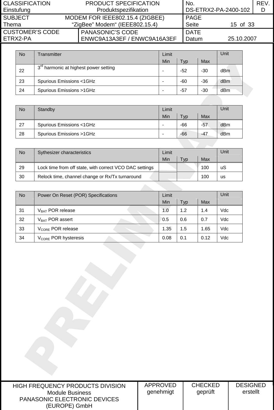
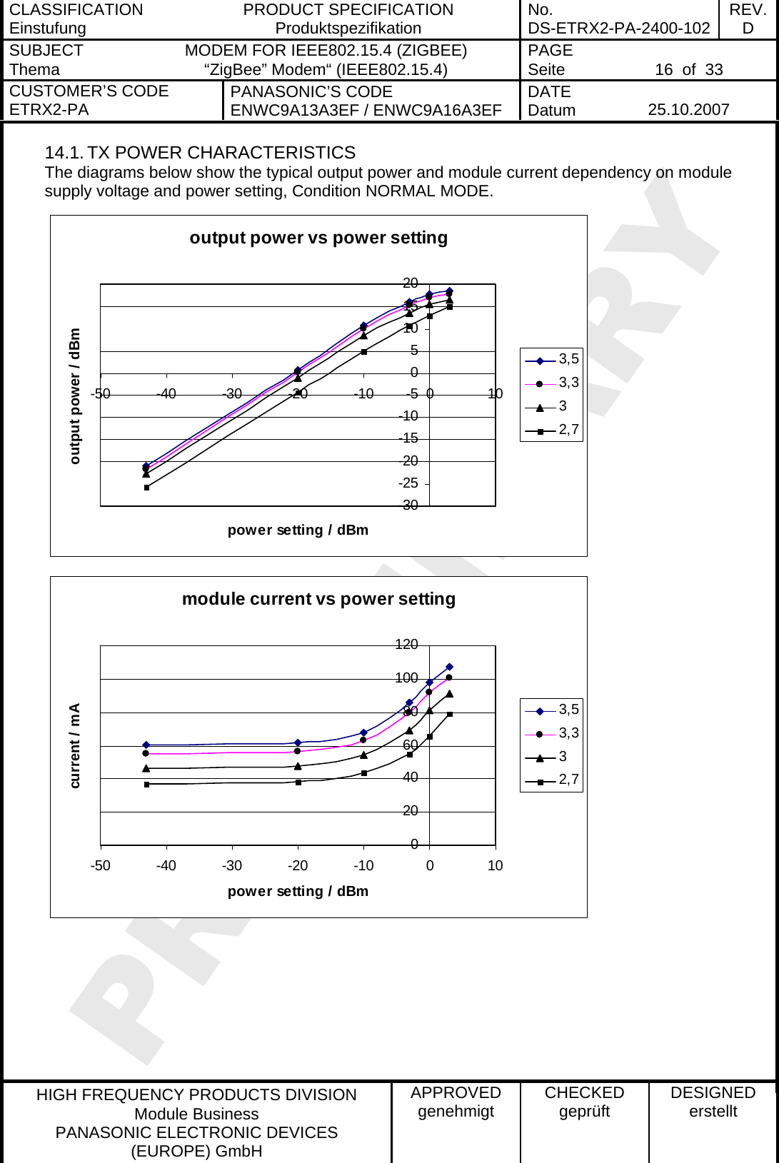
![CLASSIFICATION Einstufung PRODUCT SPECIFICATION Produktspezifikation No. DS-ETRX2-PA-2400-102 REV.D SUBJECT Thema MODEM FOR IEEE802.15.4 (ZIGBEE) “ZigBee” Modem“ (IEEE802.15.4) PAGE Seite 14 of 33 CUSTOMER’S CODE ETRX2-PA PANASONIC’S CODE ENWC9A13A3EF / ENWC9A16A3EF DATE Datum 25.10.2007 HIGH FREQUENCY PRODUCTS DIVISION Module Business PANASONIC ELECTRONIC DEVICES (EUROPE) GmbH APPROVED genehmigt CHECKED geprüft DESIGNED erstellt 14. AC ELECTRICAL CHARACTERISTICS conditions: VBAT = 3.3V, Tamb = 25°C, NORMAL MODE measured with 50Ω terminal load at pin 38 RF or U.FL socket, for all channels number 11,12,..., 26 according to [1] No Limit Unit Receiver Min Typ Max 1 Sensitivity for 1% Packet Error Rate (PER) -85 -97 - dBm 2 Sens. for 1% Packet Error Rate (PER) BOOST MODE -85 -98 - dBm 3 Saturation (maximum input level for correct operation, low gain) 0 4 - dBm 4 Adjacent Channel Rejection (1% PER and desired signal –82dBm acc. to [1]) 30 dB 5 Alternate Channel Rejection (1% PER and desired signal –82dBm acc. to [1]) 40 dB 6 Channel Rejection for all other channels (1% PER and desired signal –82dBm acc. to [1]) 40 dB 7 802.11g rejection centered at +12MHz or –13MHz (1% PER and desired signal –82dBm acc. to [1]) 40 dB 8 Co-channel rejection (1% PER and desired signal –82dBm acc. to [1]) -6 dBc 9 RF frontend filter attenuation for interferers in the range 1710-1910MHz 30 dB 10 Relative frequency error (2x40ppm required by [1]) -120 120 ppm 11 Relative timing error (2x40ppm required by [1]) -120 120 ppm 12 Linear RSSI range 40 50 dB 13 Spurious Emissions <1GHz - -74 -57 dBm 14 Spurious Emissions >1GHz - T.B.D. -47 dBm No Limit Unit Transmitter Min Typ Max 14 Output power at highest power setting (2) NORMAL MODE BOOST MODE 14 15 17,5 18,5 20 dBm 15 Output power at power setting -20dBm 0 dBm 16 Output power at lowest power setting -22 dBm 17 Peak error vector magnitude as per IEEE802.15.4 10 35 % 18 Carrier frequency error -40 40 ppm 19 PSD mask relative at 3.5MHz distance from carrier Acc. to IEEE802.15.4 6.5.3.1 -20 -36 dB 20 PSD mask absolute at 3.5MHz distance from carrier Acc. to IEEE802.15.4 6.5.3.1(2) -30 t.b.d. dBm 21 2nd harmonic at highest power setting - -60 -30 dBm](https://usermanual.wiki/Panasonic-Devices-Europe/EM250B/User-Guide-860168-Page-14.png)
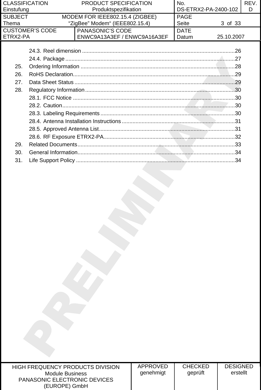
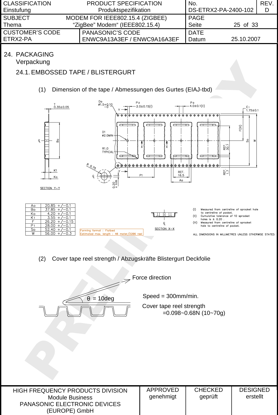
![CLASSIFICATION Einstufung PRODUCT SPECIFICATION Produktspezifikation No. DS-ETRX2-PA-2400-102 REV.D SUBJECT Thema MODEM FOR IEEE802.15.4 (ZIGBEE) “ZigBee” Modem“ (IEEE802.15.4) PAGE Seite 18 of 33 CUSTOMER’S CODE ETRX2-PA PANASONIC’S CODE ENWC9A13A3EF / ENWC9A16A3EF DATE Datum 25.10.2007 HIGH FREQUENCY PRODUCTS DIVISION Module Business PANASONIC ELECTRONIC DEVICES (EUROPE) GmbH APPROVED genehmigt CHECKED geprüft DESIGNED erstellt 16. SOLDERING TEMPERATURE-TIME PROFILE (FOR REFLOW SOLDERING) Temperatur-Zeit Profil für die Reflowlötung 16.1. FOR LEAD SOLDER Recommended temp. profile for reflow soldering Temp.[°C] Time [s] 235°C max. 220 ±5°C 200°C150 ±10°C 90 ±30s 10 ±1s 30 +20/-10s 16.2. FOR LEAD FREE SOLDER Our used temp. profile for reflow soldering Temp.[°C] Time [s] 230°C -250°C max. 220°C150°C – 190°C 90 ±30s 30 +20/-10s Reflow permissible cycle: 2 Opposite side reflow is prohibited due to module weight.](https://usermanual.wiki/Panasonic-Devices-Europe/EM250B/User-Guide-860168-Page-18.png)
![CLASSIFICATION Einstufung PRODUCT SPECIFICATION Produktspezifikation No. DS-ETRX2-PA-2400-102 REV.D SUBJECT Thema MODEM FOR IEEE802.15.4 (ZIGBEE) “ZigBee” Modem“ (IEEE802.15.4) PAGE Seite 20 of 33 CUSTOMER’S CODE ETRX2-PA PANASONIC’S CODE ENWC9A13A3EF / ENWC9A16A3EF DATE Datum 25.10.2007 HIGH FREQUENCY PRODUCTS DIVISION Module Business PANASONIC ELECTRONIC DEVICES (EUROPE) GmbH APPROVED genehmigt CHECKED geprüft DESIGNED erstellt FCC ID: T7VEM250A19. LABELING DRAWING Kennzeichnung des Moduls durch Label The label dimensions are 13,0mm x 18,5 mm. It is suited for reflow soldering. -PA comment: change ETRX2 to ETRX2-PA add CE logo to larger label if possible B Imprint Aufdruck Description Beschreibung ETRX2-PA This is the marketing name from Telegesis, the ENW number is only integrated in the 2D Code and marked with the Z Date Code Production Date Code in the format YYMMDD, e.g. 060602 01 Indication for software revision for our final test, customer are able to flash there own software. 01Z Indication for the hardware revision, Z indicates the ES status, will be removed after MP ready. 0000001 Indication for the serial number. FCC ID: TBD This is the FCC ID, should be labelled only after FCC approval. 2D-Barcode Information in the 2D-Barcode are the serial number [7 signs], the ENW-Part-Number [11 signs], identifier for the software release [2 signs], the identifier for the hardware release [2 signs] and the production date code in the format Year-Month-Day [6 signs], separated by a semicolon. The IEEE802.15.4 MAC Address [12 characters] are stored in the EM250, therefore it could not be on the label, but must be stored in the excel sheet to have a reference betweeen MAC address and serial number. 20. RECOMMENDED LAND PATTERN Empfohlenes Land Pattern This part will be included in next revisions.](https://usermanual.wiki/Panasonic-Devices-Europe/EM250B/User-Guide-860168-Page-20.png)
![CLASSIFICATION Einstufung PRODUCT SPECIFICATION Produktspezifikation No. DS-ETRX2-PA-2400-102 REV.D SUBJECT Thema MODEM FOR IEEE802.15.4 (ZIGBEE) “ZigBee” Modem“ (IEEE802.15.4) PAGE Seite 22 of 33 CUSTOMER’S CODE ETRX2-PA PANASONIC’S CODE ENWC9A13A3EF / ENWC9A16A3EF DATE Datum 25.10.2007 HIGH FREQUENCY PRODUCTS DIVISION Module Business PANASONIC ELECTRONIC DEVICES (EUROPE) GmbH APPROVED genehmigt CHECKED geprüft DESIGNED erstellt 21.3. EMBER ZIGBEE® STACK EmberZNet (currently available in versions 2.5.4 and 3.0.1) is the ZigBee® stack provided with EM250. It supports as networking topologies true mesh, star and cluster networks. The ZigBee® devices ZigBee® Coordinator, ZigBee® Router and ZigBee® End Device are supported. For the ease of application programming EmberZNet is controlled by the application over API commands. Direct ZigBee® APS layer APIs are provided for applications that require low level ZigBee® control. According to [1] each ZigBee® device has a unique address. This address is provided by Ember Inc. with the EM250. For more information on the items above see the website of Ember Inc. (www.ember.com) and the documentation included in the Ember Insight Desktop package as part of the Ember development kits. 22. RELIABILITY TESTS Zuverlässigkeitstests The measurement should be done after exposed to room temperature and humidity for 1hour. Die Messungen sollten erst nach einer Stunde Lagerung unter normalen Bedingungen erfolgen. No. Item Punkt Limit Grenzwerte Condition Bedingung 1 Vibration test Electrical parameter should be in specification a) Freq.:10~50Hz,Amplitude:1.5mm a) 20min. / cycle,1hrs. each of XYZ axis b) Freq.:30~100Hz, 6G b) 20min. / cycle,1hrs. each of XYZ axis 2 Shock test the same as the above Dropped onto hard wood from height of 50cm for 3 times 3 Heat cycle test the same as the above -40°C for 30min. and +85°C for 30min.; each temperature 300 cycles 4 Moisture test the same as the above +60°C, 90% RH, 300h 5 Low temp. test the same as the above -40°C, 300h 6 High temp. test the same as the above +85°C, 300h 23. APPLICATION NOTES Applikationshinweise 23.1. CAUTIONS FOR SAFETY Sicherheitshinweise These specifications are intended to preserve the quality assurance of products as individual components. Before use, check and evaluate their operation when mounted on your products. Abide by these specifications, without deviation when using the products.These products may short-](https://usermanual.wiki/Panasonic-Devices-Europe/EM250B/User-Guide-860168-Page-22.png)
![CLASSIFICATION Einstufung PRODUCT SPECIFICATION Produktspezifikation No. DS-ETRX2-PA-2400-102 REV.D SUBJECT Thema MODEM FOR IEEE802.15.4 (ZIGBEE) “ZigBee” Modem“ (IEEE802.15.4) PAGE Seite 33 of 33 CUSTOMER’S CODE ETRX2-PA PANASONIC’S CODE ENWC9A13A3EF / ENWC9A16A3EF DATE Datum 25.10.2007 HIGH FREQUENCY PRODUCTS DIVISION Module Business PANASONIC ELECTRONIC DEVICES (EUROPE) GmbH APPROVED genehmigt CHECKED geprüft DESIGNED erstellt 29. RELATED DOCUMENTS Mitgeltende Dokumente [1] IEEE Standard 802.15.4 –2003 Wireless Medium Access Control (MAC) and Physical Layer (PHY) Specifications for Low-Rate Wireless Personal Area Networks (LR-WPANs) [2] Data Sheet EM250, 120-0082-000F March 23, 2006, Ember Inc. (www.ember.com) [3] Data Sheet U.FL-Series 2004.2 Hirose Ultra Small Surface Mount Coaxial Connectors - Low Profile 1.9mm or 2.4mm Mated Height [4] ETSI EN 300 328 V1.5.1 (2004-03) Electromagnetic compatibility and Radio spectrum Matters (ERM)](https://usermanual.wiki/Panasonic-Devices-Europe/EM250B/User-Guide-860168-Page-33.png)