Panasonic Devices Europe EM250B ETRX2-PA, STRX2-PA, ETRX2HR-PA, STRX2HR-PA User Manual 1
Panasonic Industrial Devices Europe GmbH ETRX2-PA, STRX2-PA, ETRX2HR-PA, STRX2HR-PA 1
Manual
CLASSIFICATION
Einstufung PRODUCT SPECIFICATION
Produktspezifikation No.
DS-ETRX2-PA-2400-102 REV.
D
SUBJECT
Thema MODEM FOR IEEE802.15.4 (ZIGBEE)
“ZigBee” Modem“ (IEEE802.15.4) PAGE
Seite
1 of 33
CUSTOMER’S CODE
ETRX2-PA PANASONIC’S CODE
ENWC9A13A3EF / ENWC9A16A3EF DATE
Datum 25.10.2007
HIGH FREQUENCY PRODUCTS DIVISION
Module Business
PANASONIC ELECTRONIC DEVICES
(EUROPE) GmbH
APPROVED
genehmigt CHECKED
geprüft DESIGNED
erstellt
Specification for Production
Panasonic Electronic Devices (Europe) GmbH
Zeppelinstrasse 19
21337 Lüneburg
Applicant / Manufacturer
Hardware
Germany
Ember Inc.
Telegesis (UK) Limited
Applicant / Manufacturer
Software
Contents Approval for Mass Production
Telegesis (UK) Limited
Customer
By signing this document, Customer accepts the validity of the below-mentioned contents and
declares his full notice to it. Some passages may be changed if required; the validity shall not be
affected thereby.
CHECKED / APPROVED:
DATE: NAME: SIGNATURE:
NOTE:
AT LEAST ONE SET OF APPROVED SPECIFICATIONS SHOULD BE RETURNED TO
THE ADDRESS OF THE ISSUING PARTY.

CLASSIFICATION
Einstufung PRODUCT SPECIFICATION
Produktspezifikation No.
DS-ETRX2-PA-2400-102 REV.
D
SUBJECT
Thema MODEM FOR IEEE802.15.4 (ZIGBEE)
“ZigBee” Modem“ (IEEE802.15.4) PAGE
Seite
2 of 33
CUSTOMER’S CODE
ETRX2-PA PANASONIC’S CODE
ENWC9A13A3EF / ENWC9A16A3EF DATE
Datum 25.10.2007
HIGH FREQUENCY PRODUCTS DIVISION
Module Business
PANASONIC ELECTRONIC DEVICES
(EUROPE) GmbH
APPROVED
genehmigt CHECKED
geprüft DESIGNED
erstellt
TABLE OF CONTENTS
1. Key Features...................................................................................................................4
2. Applications for the Module.............................................................................................4
3. Description of the Module................................................................................................5
3.1. On board DC Regulator .........................................................................................5
3.2. On Board reference Crystal ...................................................................................5
4. Scope of this Document ..................................................................................................6
5. History for this Document................................................................................................6
6. Terminal Layout...............................................................................................................7
7. Block Diagram...............................................................................................................10
8. Key Parts List ................................................................................................................10
9. Test Conditions .............................................................................................................10
10. Absolute Maximum Ratings...........................................................................................11
11. Operating Conditions.....................................................................................................11
12. DC Electrical Characteristics.........................................................................................12
13. A/D converter Characteristics........................................................................................13
14. AC Electrical Characteristics.........................................................................................14
14.1. Tx power characteristics ......................................................................................16
15. Mechanical Requirements.............................................................................................17
16. Soldering Temperature-time profile (for reflow soldering).............................................18
16.1. For lead solder .....................................................................................................18
16.2. For lead free solder..............................................................................................18
17. Module Dimensions.......................................................................................................19
18. Foot Print of the Module................................................................................................19
19. Labeling Drawing...........................................................................................................20
20. Recommended Land Pattern ........................................................................................20
21. Software ........................................................................................................................21
21.1. Software Declaration............................................................................................21
21.2. Software Tools .....................................................................................................21
21.3. Ember ZigBee® Stack .........................................................................................22
22. Reliability Tests .............................................................................................................22
23. Application Notes ..........................................................................................................22
23.1. Cautions for safety...............................................................................................22
23.2. Design engineering notes ....................................................................................23
23.3. Storage conditions ...............................................................................................24
24. Packaging......................................................................................................................25
24.1. Embossed tape / Blistergurt.................................................................................25
24.2. Component direction............................................................................................26

CLASSIFICATION
Einstufung PRODUCT SPECIFICATION
Produktspezifikation No.
DS-ETRX2-PA-2400-102 REV.
D
SUBJECT
Thema MODEM FOR IEEE802.15.4 (ZIGBEE)
“ZigBee” Modem“ (IEEE802.15.4) PAGE
Seite
3 of 33
CUSTOMER’S CODE
ETRX2-PA PANASONIC’S CODE
ENWC9A13A3EF / ENWC9A16A3EF DATE
Datum 25.10.2007
HIGH FREQUENCY PRODUCTS DIVISION
Module Business
PANASONIC ELECTRONIC DEVICES
(EUROPE) GmbH
APPROVED
genehmigt CHECKED
geprüft DESIGNED
erstellt
24.3. Reel dimension ....................................................................................................26
24.4. Package...............................................................................................................27
25. Ordering Information .....................................................................................................28
26. RoHS Declaration..........................................................................................................29
27. Data Sheet Status .........................................................................................................29
28. Regulatory Information..................................................................................................30
28.1. FCC Notice ..........................................................................................................30
28.2. Caution.................................................................................................................30
28.3. Labeling Requirements ........................................................................................30
28.4. Antenna Installation Instructions..........................................................................31
28.5. Approved Antenna List.........................................................................................31
28.6. RF Exposure ETRX2-PA......................................................................................32
29. Related Documents.......................................................................................................33
30. General Information.......................................................................................................34
31. Life Support Policy ........................................................................................................34

CLASSIFICATION
Einstufung PRODUCT SPECIFICATION
Produktspezifikation No.
DS-ETRX2-PA-2400-102 REV.
D
SUBJECT
Thema MODEM FOR IEEE802.15.4 (ZIGBEE)
“ZigBee” Modem“ (IEEE802.15.4) PAGE
Seite
4 of 33
CUSTOMER’S CODE
ETRX2-PA PANASONIC’S CODE
ENWC9A13A3EF / ENWC9A16A3EF DATE
Datum 25.10.2007
HIGH FREQUENCY PRODUCTS DIVISION
Module Business
PANASONIC ELECTRONIC DEVICES
(EUROPE) GmbH
APPROVED
genehmigt CHECKED
geprüft DESIGNED
erstellt
1. KEY FEATURES
Schlüsseleigenschaften
• short range 2,4GHz ISM band IEEE802.15.4 [1] compliant transceiver
• Complete system based on the ZigBee ® compliant platform EM250 that combines the
transceiver with a powerful, efficient industry proven 16-bit microprocessor with
comprehensive hardware supported network-level debugging features
• designed specifically for use with EmberZNet, Embers ZigBee® compliant embedded
mesh networking
• powerful 16-bit microprocessor
• 128k flash ROM and 5k of SRAM memory
• high Rx sensitivity of –97dBm at 1% Packet Error Rate
• increased Tx output power setting range from -20dBm to +17dBm
• Small size 20,5mm x 37,5mm x 2.8mm
• single port antenna terminal (pcb pad, U.FL socket or chip antenna versions available)
• Integrated ADC module with 12-bit resolution
• two 16-bit general purpose timers; one 16-bit sleep timer
• 17 GPIO pins with alternate functions
• two sleep modes for increased battery life
• low voltage detect/reset
• complies with ETSI EN300328 and FCC part15
2. APPLICATIONS FOR THE MODULE
Anwendungen für das Modul
• ZigBee® Coordinators,Routers and End Devices working in star and mesh networks
• Wireless sensor and actuator networks
• Remote control and wire replacement in industrial systems
• Building automation and control
• Inventory and logistics management
• HID (Human Interface Devices)
• Toys
• Home gateways
CLASSIFICATION
Einstufung PRODUCT SPECIFICATION
Produktspezifikation No.
DS-ETRX2-PA-2400-102 REV.
D
SUBJECT
Thema MODEM FOR IEEE802.15.4 (ZIGBEE)
“ZigBee” Modem“ (IEEE802.15.4) PAGE
Seite
5 of 33
CUSTOMER’S CODE
ETRX2-PA PANASONIC’S CODE
ENWC9A13A3EF / ENWC9A16A3EF DATE
Datum 25.10.2007
HIGH FREQUENCY PRODUCTS DIVISION
Module Business
PANASONIC ELECTRONIC DEVICES
(EUROPE) GmbH
APPROVED
genehmigt CHECKED
geprüft DESIGNED
erstellt
3. DESCRIPTION OF THE MODULE
Beschreibung des Moduls
ETRX2-PA contains the single chip EM250 [2] from Ember Inc., a 24MHz reference crystal and
RF frontend circuitry optimized for best RF performance. As single ended RF output the module
is available with integrated antenna or 50ohms or U.FL male socket [3] or 50 ohms pad terminal
on the bottom of the module.
Compared to ETRX2 the ETRX2-PA module allows extended range of operation by means
of an integrated high efficieny power amplifier inserted in the Tx path.
A low loss LTCC bandpassfilter for the 2,4GHz I.S.M. band has an effect on both Tx and Rx
path. As a result for Rx mode the immunity against interferers (for example operating at 1,8
GHz) is improved compared to ETRX2.
Two additional hardware options are available on request:
3.1. ON BOARD DC REGULATOR
Although the EM250 already contains a dc regulator internally, the module can be
requested with an extra integrated onboard dc regulator. Some applications could benefit
from this additional regulator because as of for example:
(1) Further extension of the input voltage range or
(2) Extented battery life by replacing the regulator within EM250 by a special ultra low
quiescent current regulator or
(3) allowing for operation on very noisy power supplies
Two different types of regulators can be chosen, a linear low dropout (LDO) type or a high
efficiency switched buck regulator.
Depending on the power supply conditions of the application the optimum regulator can be
selected on demand.
3.2. ON BOARD REFERENCE CRYSTAL
A second option that is available is an on board 32,768kHz crystal reference. This option is
provided for applications that require a precision reference clock.
Please contact the manufacturer if one of the options could be useful for your product design.
ETRX2-PA is used for ZigBee® (www.zigbee.org) applications working with
EmberZNetTM of Ember Inc. (www.ember.com). EmberZNetTM is a fully ZigBee® compliant
networking stack. For code development Insight DesktopTM, a comprehensive
integrated development environment (IDE) and C-language compiler toolchain from
Ember Inc. is required. Insight DesktopTM is part of Ember development kits and
can currently be purchased together with programming adaptors as EM250 jumpstart kit at a
price of USD 2500,- directly from Ember Inc. (www.ember.com).
CLASSIFICATION
Einstufung PRODUCT SPECIFICATION
Produktspezifikation No.
DS-ETRX2-PA-2400-102 REV.
D
SUBJECT
Thema MODEM FOR IEEE802.15.4 (ZIGBEE)
“ZigBee” Modem“ (IEEE802.15.4) PAGE
Seite
6 of 33
CUSTOMER’S CODE
ETRX2-PA PANASONIC’S CODE
ENWC9A13A3EF / ENWC9A16A3EF DATE
Datum 25.10.2007
HIGH FREQUENCY PRODUCTS DIVISION
Module Business
PANASONIC ELECTRONIC DEVICES
(EUROPE) GmbH
APPROVED
genehmigt CHECKED
geprüft DESIGNED
erstellt
When using ZigBee® technology for a product the following additional costs have to
be taken into account:
(1) Membership of the ZigBee® Alliance, as least as adopter member for US$
3.500,-.
(2) The cost of a ZigBee® product certification at a testhouse (TÜV Rheinland)
ranges from approximately US$ 2.500,- to US$ 10.000,-, depending on the
implemented software.
(3) Products qualifying for ZigBee® certification at the ZigBee® Alliance need a
logo administration fee of US$ 1000,- for the first product, and US$ 500,- for
each additional product.
For more details on ZigBee® software see also part 21.
4. SCOPE OF THIS DOCUMENT
Umfang dieses Dokumentes
This product specification applies to the ZigBee ready modem ENWC9A13A3EF /
ENWC9A16A3EF.
The last character indicates different versions (refer to part 28 Ordering Information).
The used chip is the EM250 from the US company Ember Inc. www.ember.com.
Diese Produktionsunterlagen beziehen sich auf das ZigBee ready Modem ENWC9A13A3EF /
ENWC9A16A3EF.
Das letzte Zeichen bezeichnet verschiedene Versionen (Erklärung im Kapitel 25 Ordering
Information). Der verwendete ZigBee Chip ist EM250 der US Firma Ember Inc.
5. HISTORY FOR THIS DOCUMENT
Versionsverwaltung dieses Dokumentes
Revision
Version
Date
Datum
Modification / Remarks
Änderungen / Bemerkungen
A 06.06.2007 Preliminary
B 13.06.2007 Corrections based on review of Telegesis
C 05.10.2007 Updated parts 11 to 14 because of changed pcw and partslist (EMC issue)
D 25.10.2007 Due to FCC qualification update in chapter 28.1, 28.3, 28.4, 28.6.
CLASSIFICATION
Einstufung PRODUCT SPECIFICATION
Produktspezifikation No.
DS-ETRX2-PA-2400-102 REV.
D
SUBJECT
Thema MODEM FOR IEEE802.15.4 (ZIGBEE)
“ZigBee” Modem“ (IEEE802.15.4) PAGE
Seite
7 of 33
CUSTOMER’S CODE
ETRX2-PA PANASONIC’S CODE
ENWC9A13A3EF / ENWC9A16A3EF DATE
Datum 25.10.2007
HIGH FREQUENCY PRODUCTS DIVISION
Module Business
PANASONIC ELECTRONIC DEVICES
(EUROPE) GmbH
APPROVED
genehmigt CHECKED
geprüft DESIGNED
erstellt
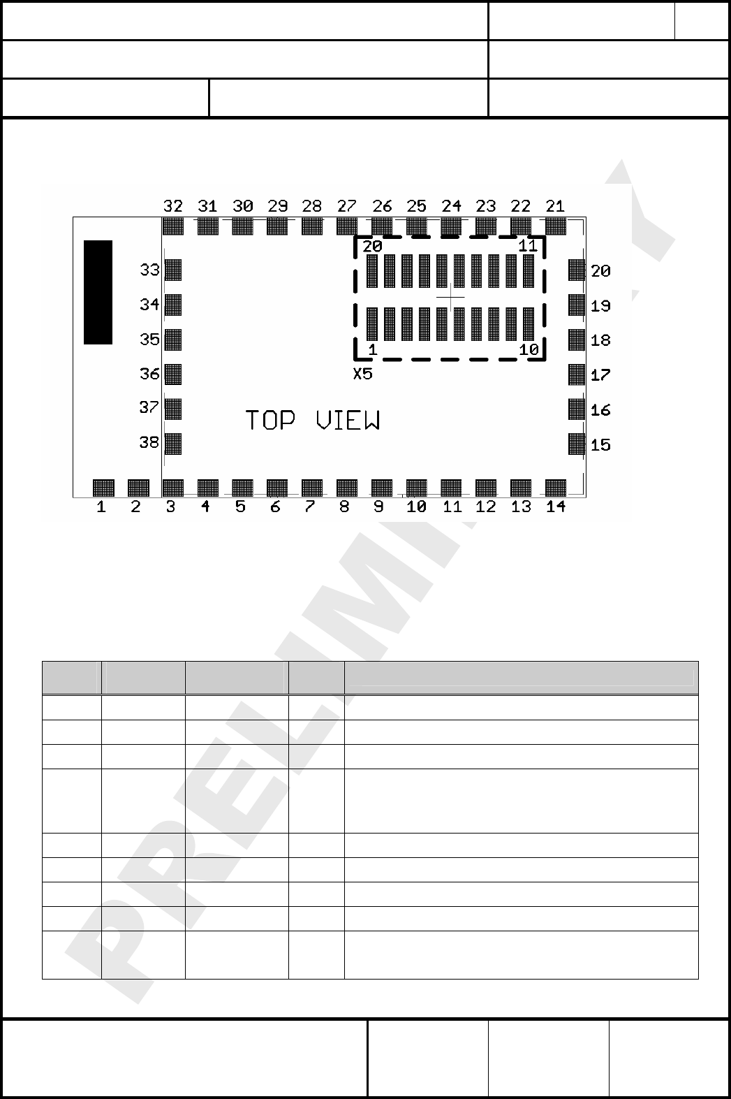
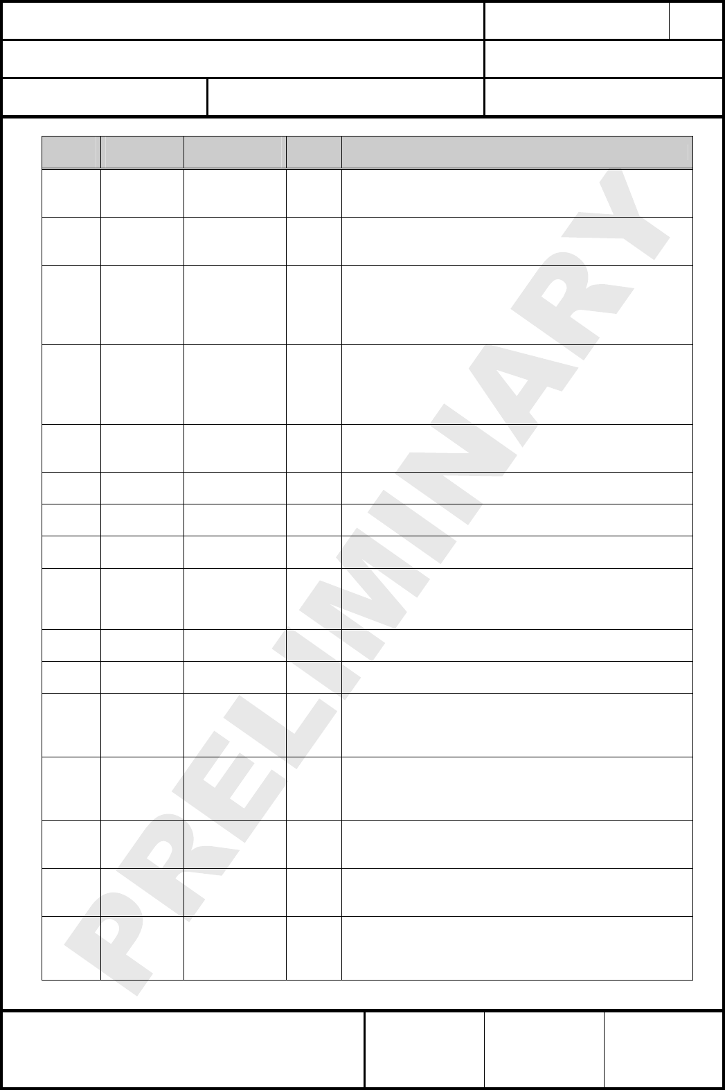
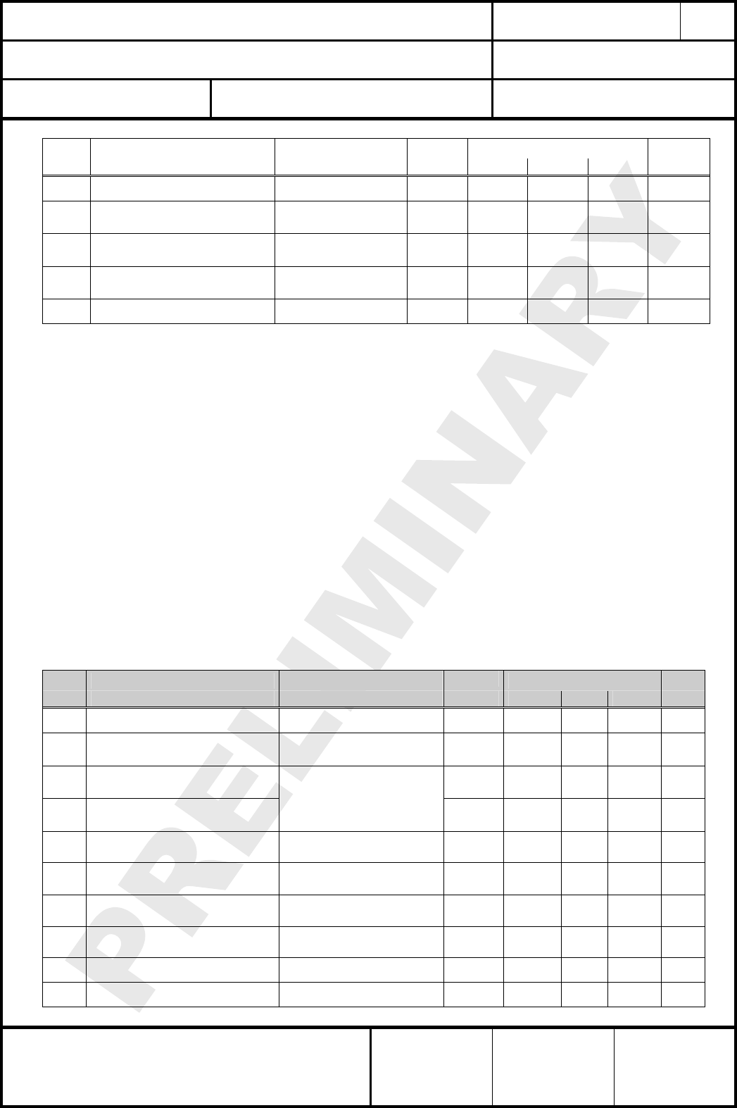
6. TERMINAL LAYOUT
Anschlußbelegung
The table below informs about the 38 module pin signals for direct SMD soldering of ETRX2-PA
to the application board. The signal names are identical to the signal names of EM250, except
for RF and VC1.
The pin numbers in brackets () are the related pins of the pin/header connector X5, which is only
mounted for special plug versions.
Pin
No.
Pin
Name
Signal
Name
Pin
Type Description
1(3) GND1 GND I/O ground
2 RF RF I/O RF input/output terminal
3 GND3 GND I/O ground
4(1) GPIO0
GPIO0
MOSI
MOSI
TMR1IA.1
I/O
O
I
I
Digital I/O
SPI master data out of serial controller SC2
SPI slave data in of serial controller SC2
Capture Input A of Timer 1
5(2) REG_OUT REG_OUT O output of EM250 regulator voltage VREG_OUT (1)
6 GND2 GND I/O ground
7(10) VBAT VBAT I module dc supply voltage
8 GND3 GND I/O ground
9(4) GPIO4
GPIO4
ADC0
PTI_EN
I/O
Analog
O
Digital I/O
ADC Input 0
Frame signal of Packet Trace Interface (PTI)
CLASSIFICATION
Einstufung PRODUCT SPECIFICATION
Produktspezifikation No.
DS-ETRX2-PA-2400-102 REV.
D
SUBJECT
Thema MODEM FOR IEEE802.15.4 (ZIGBEE)
“ZigBee” Modem“ (IEEE802.15.4) PAGE
Seite
8 of 33
CUSTOMER’S CODE
ETRX2-PA PANASONIC’S CODE
ENWC9A13A3EF / ENWC9A16A3EF DATE
Datum 25.10.2007
HIGH FREQUENCY PRODUCTS DIVISION
Module Business
PANASONIC ELECTRONIC DEVICES
(EUROPE) GmbH
APPROVED
genehmigt CHECKED
geprüft DESIGNED
erstellt
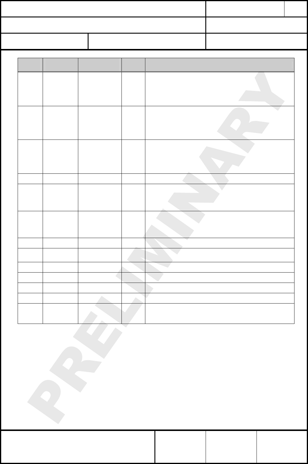
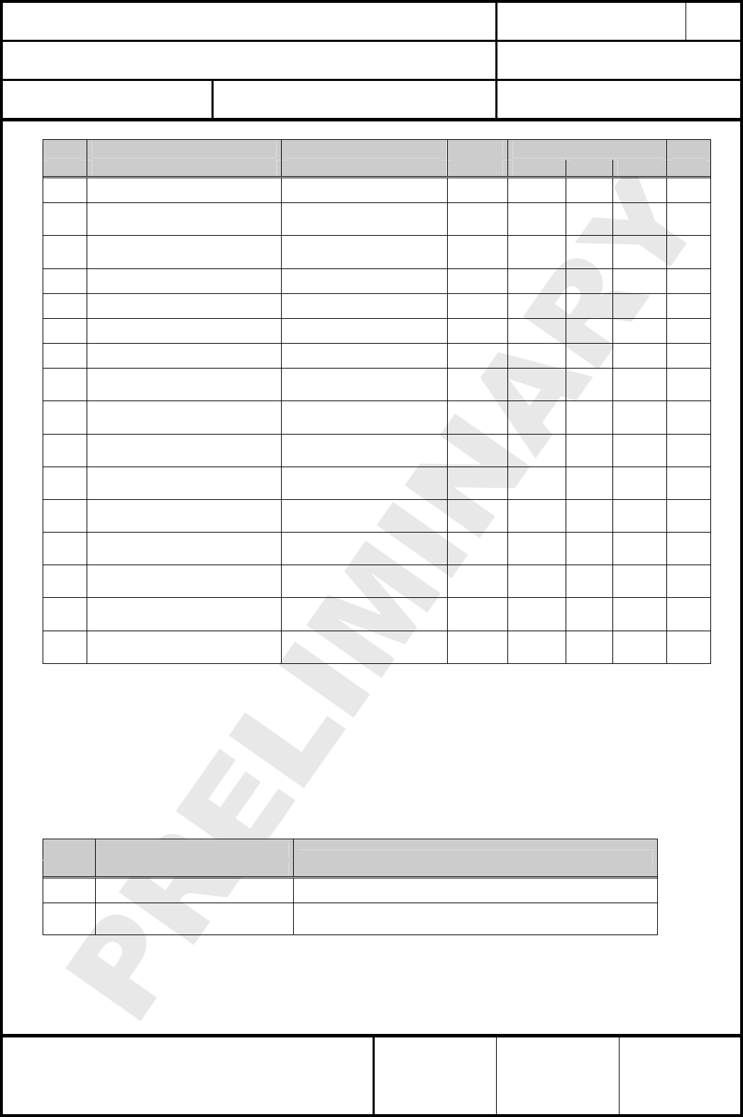
Pin
No.
Pin
Name
Signal
Name
Pin
Type Description
10(5) GPIO5
GPIO5
ADC1
PTI_DATA
I/O
Analog
O
Digital I/O
ADC Input 1
Data signal of Packet Trace Interface (PTI)
11(6) GPIO3
GPIO3
SSEL
TMR1IB.1
I/O
I
I
Digital I/O
SPI slave select of Serial Controller SC2
Capture Input B of Timer 1
12(7) GPIO2
GPIO2
MSCLK
MSCLK
SCL
TMR2IB.2
I/O
O
I
I/O
I
Digital I/O
SPI master clock of Serial Controller SC2
SPI slave clock of Serial Controller SC2
I2C clock of Serial Controller SC2
Capture Input B of Timer 2
13(8) GPIO1
GPIO1
MISO
MISO
SDA
TMR2IA.2
I/O
I
O
I/O
I
Digital I/O
SPI master data in of Serial Controller SC2
SPI slave data out of Serial Controller SC2
I2C data of Serial Controller SC2
Capture Input A of Timer 2
14(9) GPIO12
GPIO12
RTS
TMR2IB.1
I/O
O
I
Digital I/O
UART RTS handshake of Serial Controller SC1
Capture Input B for Timer 2
15 GND4 GND I/O
ground
16 SIF_CLK SIF_CLK I Serial interface, clock (internal pull-down)
17 SIF_MISO SIF_MISO O Serial interface, master in / slave out
18 SIF_MOSI SIF_MOSI I
Serial interface, master out / slave in.
In order to guarantee the deep sleep current limits as
specified this pin has to be pulled to GND externally, typically
with a 10 kiloohms resistor.
19 SIF_LOADB SIF_LOADB I/O
Serial interface, load strobe
(open-collector with internal pull-up)
20 GND5 GND I/O
ground
21(11) GPIO6
GPIO6
ADC2
TMR2CLK
TMR1ENMSK
I/O
Analog
I
I
Digital I/O
ADC Input 2
External clock input of Timer 2
External enable mask of Timer 1
22(12) GPIO11
GPIO11
CTS
MCLK
TMR2IA.1
I/O
I
O
I
Digital I/O
UART CTS handshake of Serial Controller SC1
SPI master clock of Serial Controller SC1
Capture Input A of Timer 2
23(13) GPIO13
GPIO13
TMR2OA
TMR1IA.3
I/O
O
I
Digital I/O
Waveform Output A of Timer 2
Capture Input A of Timer 1
24(14) RESET RESET I
active low module reset (internal pull-up)
25(15) GPIO14
GPIO14
TMR2OB
TMR1IB.3
IRQB
I/O
O
I
I
Digital I/O
Waveform Output B of Timer 2
Capture Input B of Timer 1
External interrupt source B
CLASSIFICATION
Einstufung PRODUCT SPECIFICATION
Produktspezifikation No.
DS-ETRX2-PA-2400-102 REV.
D
SUBJECT
Thema MODEM FOR IEEE802.15.4 (ZIGBEE)
“ZigBee” Modem“ (IEEE802.15.4) PAGE
Seite
9 of 33
CUSTOMER’S CODE
ETRX2-PA PANASONIC’S CODE
ENWC9A13A3EF / ENWC9A16A3EF DATE
Datum 25.10.2007
HIGH FREQUENCY PRODUCTS DIVISION
Module Business
PANASONIC ELECTRONIC DEVICES
(EUROPE) GmbH
APPROVED
genehmigt CHECKED
geprüft DESIGNED
erstellt
Pin
No.
Pin
Name
Signal
Name
Pin
Type Description
26(16) GPIO8
GPIO8
VREF_OUT
TMR1CLK
TMR2ENMSK
IRQA
I/O
Analog
I
I
I
Digital I/O
ADC reference output
External clock input of Timer 1
External enable mask of Timer 2
External interupt source A
27(18) GPIO9
GPIO9
TXD
MO
MSDA
TMR1IA.2
I/O
O
O
I/O
I
Digital I/O
UART transmit data of Serial Controller SC1
SPI master data out of Serial Controller SC1
I2C data of Serial Controller SC2
Capture Input A of Timer 1
28(17) GPIO10
GPIO10
RXD
MI
MSCL
TMR1IB.2
I/O
I
I
I/O
I
Digital I/O
UART receive data of Serial Controller SC1
SPI master data in of Serial Controller SC1
I2C clock of Serial Controller SC1
Capture Input B of Timer 2
29 GND6 GND I/O ground
30(19) GPIO15
GPIO15
TMR1OA
TMR2IA.3
IRQC
I/O
O
I
I
Digital I/O
Waveform Output A of Timer 1
Capture Input A of Timer 2
External interrupt source C
31(20) GPIO16
GPIO16
TMR1OB
TMR2IB.3
IRQD
I/O
O
I
I
Digital I/O
Waveform Output B of Timer 1
Capture Input B of Timer 2
External interrupt source D
32 GND7 GND I/O ground
33 VC1 VCONT O
Do not connect.
Internal control voltage for the power amplifier (2)
34 GND8 GND I/O ground
35 GND9 GND I/O ground
36 GND10 GND I/O ground
37 GND11 GND I/O ground
38 GPIO7
GPIO7
ADC3
REG_EN
I/O
Analog
O
Digital I/O
ADC Input 3
External regulator open collector output
Notes:
(1) In case the onboard regulator option is mounted this pin is connected to the output voltage of the
onboard regulator option and NOT to the output voltage VREG_OUT of the EM250.
(2) VCONT is the internal amplifier gain control voltage, resistive external loading to ground can
reduce the amplifier gain and therefore lower the maximum available module Tx output power.
For most of the applications this pin is NOT connected and the amplifier is working at maximum
gain.
CLASSIFICATION
Einstufung PRODUCT SPECIFICATION
Produktspezifikation No.
DS-ETRX2-PA-2400-102 REV.
D
SUBJECT
Thema MODEM FOR IEEE802.15.4 (ZIGBEE)
“ZigBee” Modem“ (IEEE802.15.4) PAGE
Seite
10 of 33
CUSTOMER’S CODE
ETRX2-PA PANASONIC’S CODE
ENWC9A13A3EF / ENWC9A16A3EF DATE
Datum 25.10.2007
HIGH FREQUENCY PRODUCTS DIVISION
Module Business
PANASONIC ELECTRONIC DEVICES
(EUROPE) GmbH
APPROVED
genehmigt CHECKED
geprüft DESIGNED
erstellt
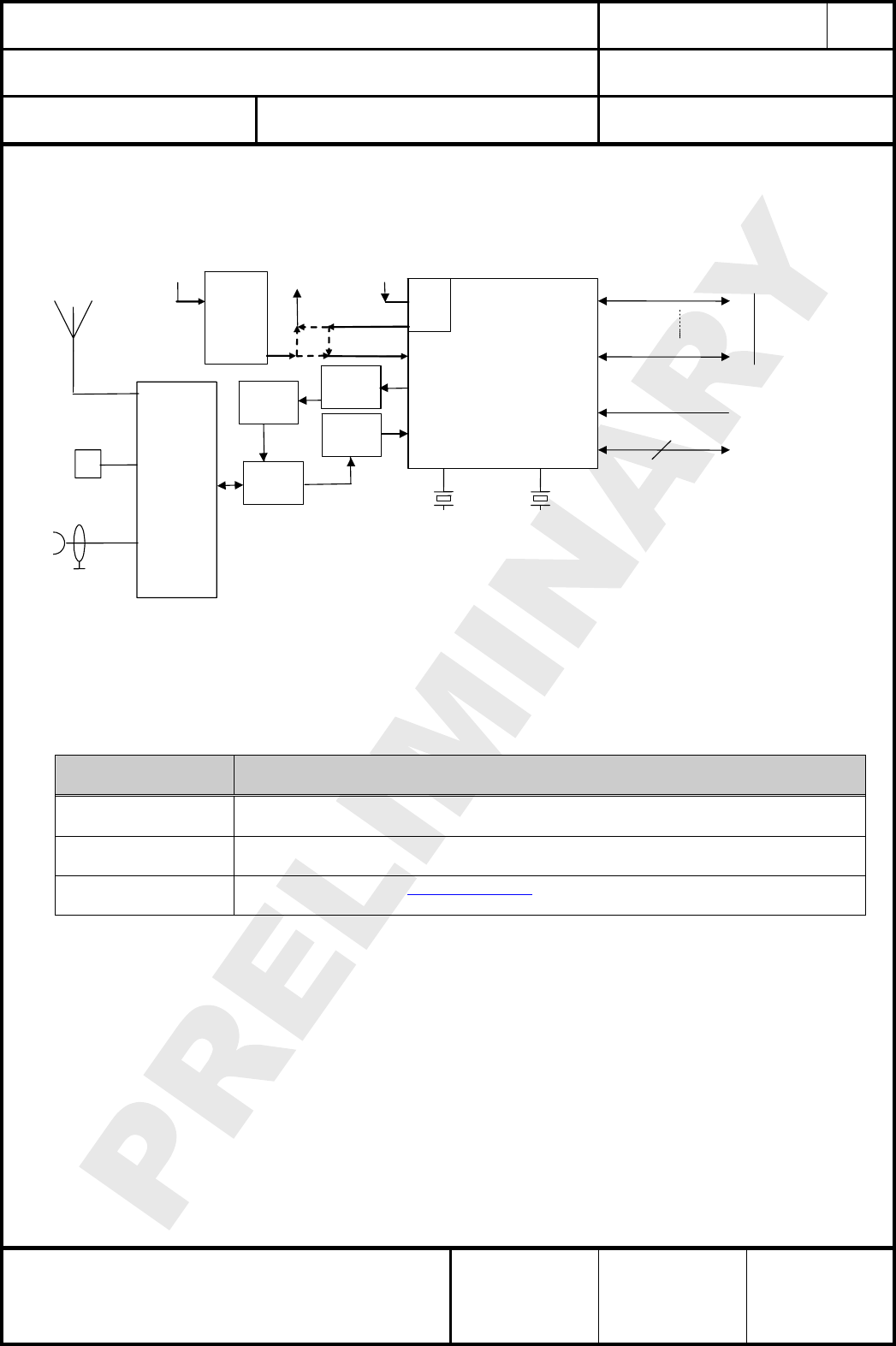
7. BLOCK DIAGRAM
Blockdiagramm
24MHz 32,768kHz
(optional)
EM250
RF transceiver 2,4GHz
16-bit XAP2b uC
128kB flash / 5k RAM
GPIO0
GPIO16 I / O
programming
4 SIF
LDO
or
DC
converte
r
(optional)
VBATVBAT VREG
RESET RESET
BALUN
integrated
antenna
pad
U.FL socket
rf
terminal
selection,
filtering and
matching
circuitry
LDO
1,8Vdc
Tx
Rx
BALUN
Rx/Tx
switch
PA
8. KEY PARTS LIST
Liste der Schlüsselkomponenten
Part Name
Teilenummer
Material
Material
P.W.Board
Leiterplatte
Glass cloth epoxide resin with gold plating
FR4 mit Goldauflage
Casing
Deckel
Material: CuNi18ZN20, thickness 0.2mm
Material: Weißblech 0,2mm Dicke
RF-IC part name
RF IC Name
EM250 from Ember Inc.(www.ember.com)
All information are based on [2] chapter 28.
9. TEST CONDITIONS
Meßbedingungen
Measurements shall be made under room temperature and humidity unless otherwise specified.
Messungen unter normalen Bedingungen, Abweichungen sind gesondert notiert.
Temperature 25 ± 10°C Humidity 40 to 85%RH
Temperatur 25 ± 10°C Luftfeuchtigkeit 40 to 85%RH
CLASSIFICATION
Einstufung PRODUCT SPECIFICATION
Produktspezifikation No.
DS-ETRX2-PA-2400-102 REV.
D
SUBJECT
Thema MODEM FOR IEEE802.15.4 (ZIGBEE)
“ZigBee” Modem“ (IEEE802.15.4) PAGE
Seite
11 of 33
CUSTOMER’S CODE
ETRX2-PA PANASONIC’S CODE
ENWC9A13A3EF / ENWC9A16A3EF DATE
Datum 25.10.2007
HIGH FREQUENCY PRODUCTS DIVISION
Module Business
PANASONIC ELECTRONIC DEVICES
(EUROPE) GmbH
APPROVED
genehmigt CHECKED
geprüft DESIGNED
erstellt
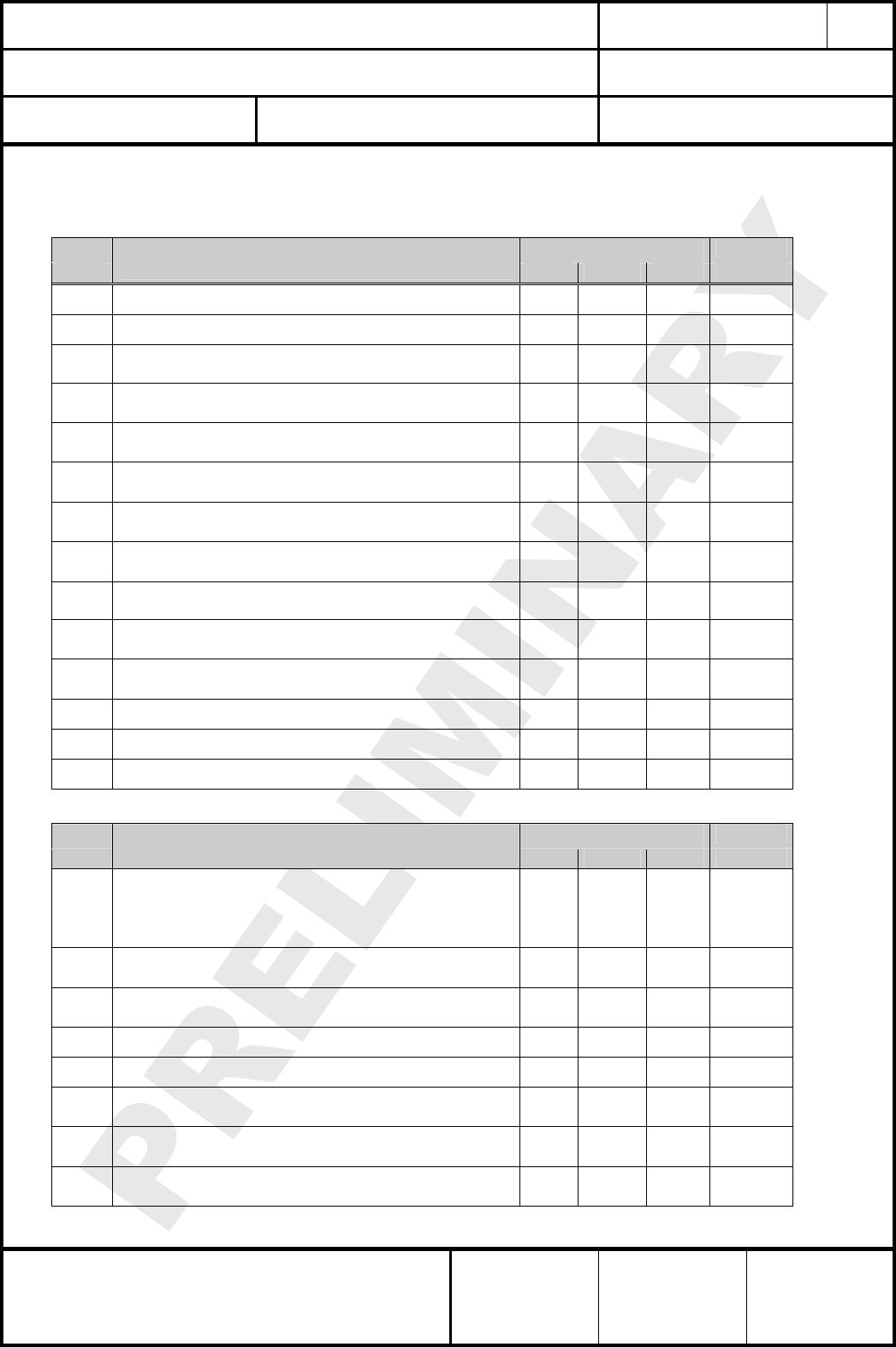
10. ABSOLUTE MAXIMUM RATINGS
Absolute Grenzwerte
The maximum ratings may not be exceeded under any circumstances, not even momentarily
and individually, as permanent damage to the module will result.
No. Item
Punkt
Symbol
Zeichen
Absolute Maximum Ratings
Absolute Grenzwerte
Unit
Einheit
1 Supply voltage VBAT -0.1 to +3.5 Vdc
2
Voltage on any GPIO[16:0] ,
SIF_CLK, SIF_MISO,
SIF_MOSI, SIF_LOADB,
OSC32A, OSC32B, RESET,
REG_OUT
Vin -0.3 to VBAT+0.3 Vdc
3 Storage temperature range Tstg -40 to +105 °C
4 Operating temperature range Top -40 to +85 °C
5 Input RF level Pmax 0 dBm
6 ESD on any pin (1) according to
Human Body Model (HBM)
circuit description VTHHBM ±2 kV
7 Lead temperature
Löttemperatur TDeath T.B.D. °C
Notes:
(1) Input must be current limited to the value specified.
11. OPERATING CONDITIONS
Betriebsbedingungen
VBAT = 3.3V, Tamb = 25°C , NORMAL MODE if nothing else stated
No. Item Condition / Remark Symbol Value Unit
Min Typ Max
1 Supply voltage The typical value
is recommended
VDD 2.7 3.3 3.5 Vdc
2 RF Input Frequency fC2405 2480 MHz
3 RF Input Power pIN 0 dBm
4 EM250 Tx power mode
setting NORMAL MODE or BOOST MODE(1) and
external PA
5 EM250 Tx output power
setting Channels 1-14
pOUTSET -43 +3 dBm
6 EM250 Tx output power
setting(2) Channel 0 pOUTSET -43 -3 dBm
7 EM250 Tx output power
setting(2) Channel 15
pOUTSET -43 -14 dBm
8
To 5. corresponding typical
module output power.
For more details see part 14.
Channels 1-14
NORMAL MODE
BOOST MODE
pOUT
-22
-21
+17,5
+18,5
dBm
dBm
9 Allowed Tx duty cycle Maximum output
power set and 0dBi 10 %
CLASSIFICATION
Einstufung PRODUCT SPECIFICATION
Produktspezifikation No.
DS-ETRX2-PA-2400-102 REV.
D
SUBJECT
Thema MODEM FOR IEEE802.15.4 (ZIGBEE)
“ZigBee” Modem“ (IEEE802.15.4) PAGE
Seite
12 of 33
CUSTOMER’S CODE
ETRX2-PA PANASONIC’S CODE
ENWC9A13A3EF / ENWC9A16A3EF DATE
Datum 25.10.2007
HIGH FREQUENCY PRODUCTS DIVISION
Module Business
PANASONIC ELECTRONIC DEVICES
(EUROPE) GmbH
APPROVED
genehmigt CHECKED
geprüft DESIGNED
erstellt
No. Item Condition / Remark Symbol Value Unit
Min Typ Max
Antenna (3)
10 Logic Input Voltage Low
pOUTT 0 0.2x
VBAT V
11 Logic Input Voltage High VIH 0.8x
VBAT VBAT V
12 SPI clock rate The typical value is
recommended
fSPI 12 MHz
13 Operating temperature range Top -40 +85 °C
Notes: ETRX2-PA is designed to comply to the standards and regulations listed in part 29.
The conditions for compliance are:
BOOST MODE is allowed with some restrictions :
In order to stay within the output power limits 20dBm (EN300 328) and -30dBm PSD mask
absolute (IEEE802.15.4) the power setting value is limited to 0dBm maximum for supply
voltages above 3,3Vdc or operating temperatures below 0°C.
(1) On the lowest channel 0 (2405MHz) and the highest channel 15 (2480MHz) the maximum
allowed output power settings are limited to the maximum values stated above in order
to not exceed the the spectral power density limits at the 2,4GHz I.S.M. band edges under
extreme conditions as stated in part 4.3.3 “Frequency Range” of [1]
(2) With these settings and duty cycles below 10% the limits for “Maximum Spectral Output Power
density” according to part 4.3.2 of [1] are not exceeded. For lower antenna gain and/or
lower Tx output power the duty cycle may be increased according to the formula in [1].
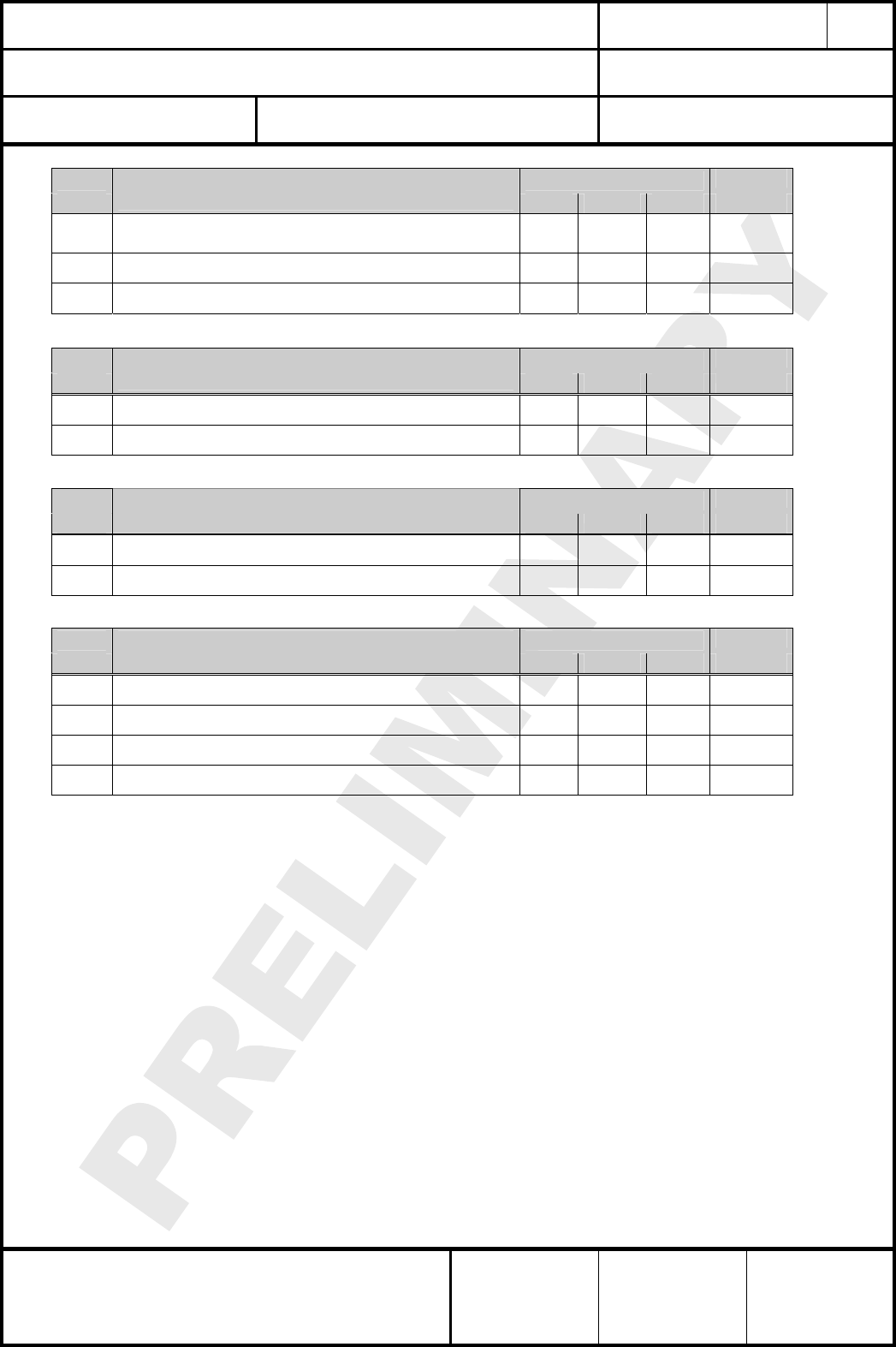
12. DC ELECTRICAL CHARACTERISTICS
conditions: VBAT = 3.3V, Tamb = 25°C, NORMAL MODE if nothing else stated
No. Item Condition / Remark Symbol Value Unit
Min Typ Max
1 Module supply voltage VBAT VBAT 2.7 3.3 3.5 Vdc
2 Internal regulated core voltage connected to
REG_OUT pin 2 (1) VCORE 1.7 1.8 1.9 Vdc
3 Quiescent current, excluding
internal RC oscillator
ISLEEP 0.8 3.0 uA
4 Quiescent current, including
32,768kHz oscillator
ISLEEP 1.5 3.5 uA
5 Transmit current consumption +17,5dBm module output
power ITXVBAT 106 120 mA
6 Transmit current consumption
BOOST MODE +18,5dBm module output
power ITXVBAT 121 120 mA
7 Transmit current consumption +10dBm module output
power ITXVBAT 63 mA
8 Transmit current consumption +0dBm module output
power ITXVBAT 56 mA
9 Receive current consumption total IRX 37 mA
10 External load on internal connected to IREG_OUT 2 mA
CLASSIFICATION
Einstufung PRODUCT SPECIFICATION
Produktspezifikation No.
DS-ETRX2-PA-2400-102 REV.
D
SUBJECT
Thema MODEM FOR IEEE802.15.4 (ZIGBEE)
“ZigBee” Modem“ (IEEE802.15.4) PAGE
Seite
13 of 33
CUSTOMER’S CODE
ETRX2-PA PANASONIC’S CODE
ENWC9A13A3EF / ENWC9A16A3EF DATE
Datum 25.10.2007
HIGH FREQUENCY PRODUCTS DIVISION
Module Business
PANASONIC ELECTRONIC DEVICES
(EUROPE) GmbH
APPROVED
genehmigt CHECKED
geprüft DESIGNED
erstellt
No. Item Condition / Remark Symbol Value Unit
Min Typ Max
regulated core voltage REG_OUT pin 2 (1)
10 Input voltage for logic 0 VIL 0
0.2x
VBAT Vdc
11 input voltage for logic 1 VIH 0.8x
VBAT VBAT Vdc
12 Input current for logic 0 IIL -0.5 uA
13 input current for logic 1 IIH 0.5 uA
14 input pull-up resistor value RIPU 30
kΩ
15 input pull-down resistor value RIPD 30
kΩ
16 Output voltage for logic 0 VOL 0
0.18x
VBAT Vdc
17 Output voltage for logic 1 VOH 0.82x
VBAT VBAT Vdc
18 Output source current
(standard current pad) IOHS 4 mA
19 Output sink current
(standard current pad) IOLS 4 mA
20 Output source current (high
current pad: GPIO[16:13] ) IOHH 8 mA
21 Output sink current (high
current pad: GPIO[16:13] ) IOLH 8 mA
22 Total output current
for I/O pads IOH +
IOL 40 mA
23 Input voltage threshold for
OSC32A VIH_L 0.2 0.8x
VBAT Vdc
24 Output voltage level for VC1 VOH_L
0.18x
VBAT 0.82x
VBAT Vdc
(1) For more information about the internal regulated core voltage refer to part 5.7 in [2]. As the
internal regulated core voltage at REG_OUT mainly feeds circuitry on ETRX2-PA, the REG_OUT
module pin may only be slightly loaded and without feeding noise to REG_OUT.
In case the dc regulator option is mounted REG_OUT is connected to the regulator option output
instead and the internal regulated core voltage is not accessible.
13. A/D CONVERTER CHARACTERISTICS
No Item
1 ATD characteristics refer to datasheet EM250 part 5.5 ADC Module
2 ATD timing/performance
characteristics refer to datasheet EM250 part 5.5 ADC Module
CLASSIFICATION
Einstufung PRODUCT SPECIFICATION
Produktspezifikation No.
DS-ETRX2-PA-2400-102 REV.
D
SUBJECT
Thema MODEM FOR IEEE802.15.4 (ZIGBEE)
“ZigBee” Modem“ (IEEE802.15.4) PAGE
Seite
14 of 33
CUSTOMER’S CODE
ETRX2-PA PANASONIC’S CODE
ENWC9A13A3EF / ENWC9A16A3EF DATE
Datum 25.10.2007
HIGH FREQUENCY PRODUCTS DIVISION
Module Business
PANASONIC ELECTRONIC DEVICES
(EUROPE) GmbH
APPROVED
genehmigt CHECKED
geprüft DESIGNED
erstellt
14. AC ELECTRICAL CHARACTERISTICS
conditions: VBAT = 3.3V, Tamb = 25°C, NORMAL MODE measured with 50Ω terminal load at pin 38 RF or
U.FL socket, for all channels number 11,12,..., 26 according to [1]
No Limit Unit
Receiver
Min Typ Max
1 Sensitivity for 1% Packet Error Rate (PER) -85 -97 - dBm
2 Sens. for 1% Packet Error Rate (PER) BOOST MODE -85 -98 - dBm
3 Saturation (maximum input level for correct operation,
low gain) 0 4 - dBm
4 Adjacent Channel Rejection
(1% PER and desired signal –82dBm acc. to [1]) 30 dB
5 Alternate Channel Rejection
(1% PER and desired signal –82dBm acc. to [1]) 40 dB
6 Channel Rejection for all other channels
(1% PER and desired signal –82dBm acc. to [1]) 40 dB
7 802.11g rejection centered at +12MHz or –13MHz
(1% PER and desired signal –82dBm acc. to [1]) 40 dB
8 Co-channel rejection
(1% PER and desired signal –82dBm acc. to [1]) -6 dBc
9 RF frontend filter attenuation for interferers in the range
1710-1910MHz 30 dB
10 Relative frequency error
(2x40ppm required by [1]) -120 120 ppm
11 Relative timing error
(2x40ppm required by [1]) -120 120 ppm
12 Linear RSSI range 40 50 dB
13 Spurious Emissions <1GHz - -74 -57 dBm
14 Spurious Emissions >1GHz - T.B.D. -47 dBm
No Limit Unit
Transmitter
Min Typ Max
14
Output power at highest power setting (2)
NORMAL MODE
BOOST MODE
14
15
17,5
18,5 20 dBm
15 Output power at power setting -20dBm
0 dBm
16 Output power at lowest power setting
-22 dBm
17 Peak error vector magnitude as per IEEE802.15.4 10 35 %
18 Carrier frequency error -40 40 ppm
19 PSD mask relative at 3.5MHz distance from carrier
Acc. to IEEE802.15.4 6.5.3.1 -20 -36 dB
20 PSD mask absolute at 3.5MHz distance from carrier
Acc. to IEEE802.15.4 6.5.3.1(2) -30 t.b.d. dBm
21 2nd harmonic at highest power setting
- -60 -30 dBm
CLASSIFICATION
Einstufung PRODUCT SPECIFICATION
Produktspezifikation No.
DS-ETRX2-PA-2400-102 REV.
D
SUBJECT
Thema MODEM FOR IEEE802.15.4 (ZIGBEE)
“ZigBee” Modem“ (IEEE802.15.4) PAGE
Seite
15 of 33
CUSTOMER’S CODE
ETRX2-PA PANASONIC’S CODE
ENWC9A13A3EF / ENWC9A16A3EF DATE
Datum 25.10.2007
HIGH FREQUENCY PRODUCTS DIVISION
Module Business
PANASONIC ELECTRONIC DEVICES
(EUROPE) GmbH
APPROVED
genehmigt CHECKED
geprüft DESIGNED
erstellt
No Limit Unit
Transmitter
Min Typ Max
22 3rd harmonic at highest power setting
- -52 -30 dBm
23 Spurious Emissions <1GHz - -60 -36 dBm
24 Spurious Emissions >1GHz - -57 -30 dBm
No Limit Unit
Standby
Min Typ Max
27 Spurious Emissions <1GHz - -66 -57 dBm
28 Spurious Emissions >1GHz - -66 -47 dBm
No Limit Unit
Sythesizer characteristics
Min Typ Max
29 Lock time from off state, with correct VCO DAC settings 100 uS
30 Relock time, channel change or Rx/Tx turnaround 100 us
No Limit Unit
Power On Reset (POR) Specifications
Min Typ Max
31 VBAT POR release 1.0 1.2 1.4 Vdc
32 VBAT POR assert 0.5 0.6 0.7 Vdc
33 VCORE POR release 1.35 1.5 1.65 Vdc
34 VCORE POR hysteresis 0.08 0.1 0.12 Vdc
CLASSIFICATION
Einstufung PRODUCT SPECIFICATION
Produktspezifikation No.
DS-ETRX2-PA-2400-102 REV.
D
SUBJECT
Thema MODEM FOR IEEE802.15.4 (ZIGBEE)
“ZigBee” Modem“ (IEEE802.15.4) PAGE
Seite
16 of 33
CUSTOMER’S CODE
ETRX2-PA PANASONIC’S CODE
ENWC9A13A3EF / ENWC9A16A3EF DATE
Datum 25.10.2007
HIGH FREQUENCY PRODUCTS DIVISION
Module Business
PANASONIC ELECTRONIC DEVICES
(EUROPE) GmbH
APPROVED
genehmigt CHECKED
geprüft DESIGNED
erstellt
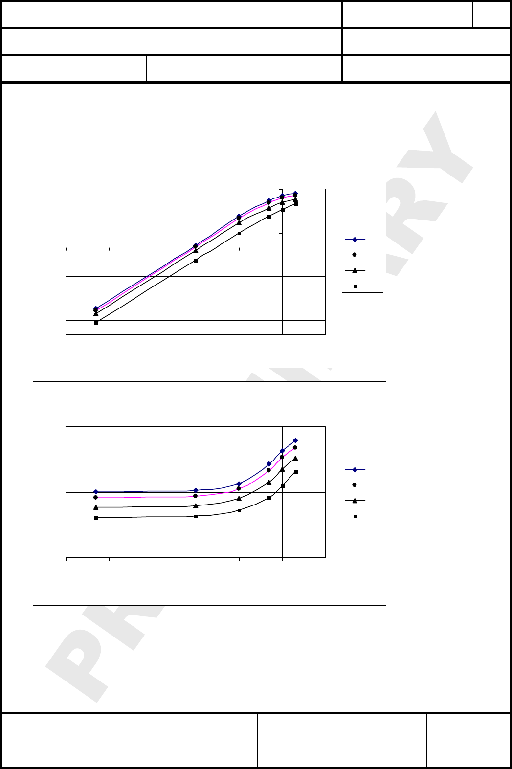
14.1. TX POWER CHARACTERISTICS
The diagrams below show the typical output power and module current dependency on module
supply voltage and power setting, Condition NORMAL MODE.
output power vs power setting
-30
-25
-20
-15
-10
-5
0
5
10
15
20
-50 -40 -30 -20 -10 0 10
power setting / dBm
output power / dBm
3,5
3,3
3
2,7
module current vs power setting
0
20
40
60
80
100
120
-50 -40 -30 -20 -10 0 10
power setting / dBm
current / mA
3,5
3,3
3
2,7
CLASSIFICATION
Einstufung PRODUCT SPECIFICATION
Produktspezifikation No.
DS-ETRX2-PA-2400-102 REV.
D
SUBJECT
Thema MODEM FOR IEEE802.15.4 (ZIGBEE)
“ZigBee” Modem“ (IEEE802.15.4) PAGE
Seite
17 of 33
CUSTOMER’S CODE
ETRX2-PA PANASONIC’S CODE
ENWC9A13A3EF / ENWC9A16A3EF DATE
Datum 25.10.2007
HIGH FREQUENCY PRODUCTS DIVISION
Module Business
PANASONIC ELECTRONIC DEVICES
(EUROPE) GmbH
APPROVED
genehmigt CHECKED
geprüft DESIGNED
erstellt
15. MECHANICAL REQUIREMENTS
Mechanische Anforderungen
No. Item
Punkt
Limit
Grenzwerte
Condition
Bedingung
1 Solderability
Lötfähigkeit
More than 75% of the soldering area shall be
coated by solder
Mehr als 75% der Lötfläche soll mit Lötpaste
bedeckt sein.
Reflow soldering with
recommendable temperature
profile
2 Resistance to
soldering heat It shall be satisfied electrical requirements and
not be mechanical damage See chapter 16.2
CLASSIFICATION
Einstufung PRODUCT SPECIFICATION
Produktspezifikation No.
DS-ETRX2-PA-2400-102 REV.
D
SUBJECT
Thema MODEM FOR IEEE802.15.4 (ZIGBEE)
“ZigBee” Modem“ (IEEE802.15.4) PAGE
Seite
18 of 33
CUSTOMER’S CODE
ETRX2-PA PANASONIC’S CODE
ENWC9A13A3EF / ENWC9A16A3EF DATE
Datum 25.10.2007
HIGH FREQUENCY PRODUCTS DIVISION
Module Business
PANASONIC ELECTRONIC DEVICES
(EUROPE) GmbH
APPROVED
genehmigt CHECKED
geprüft DESIGNED
erstellt
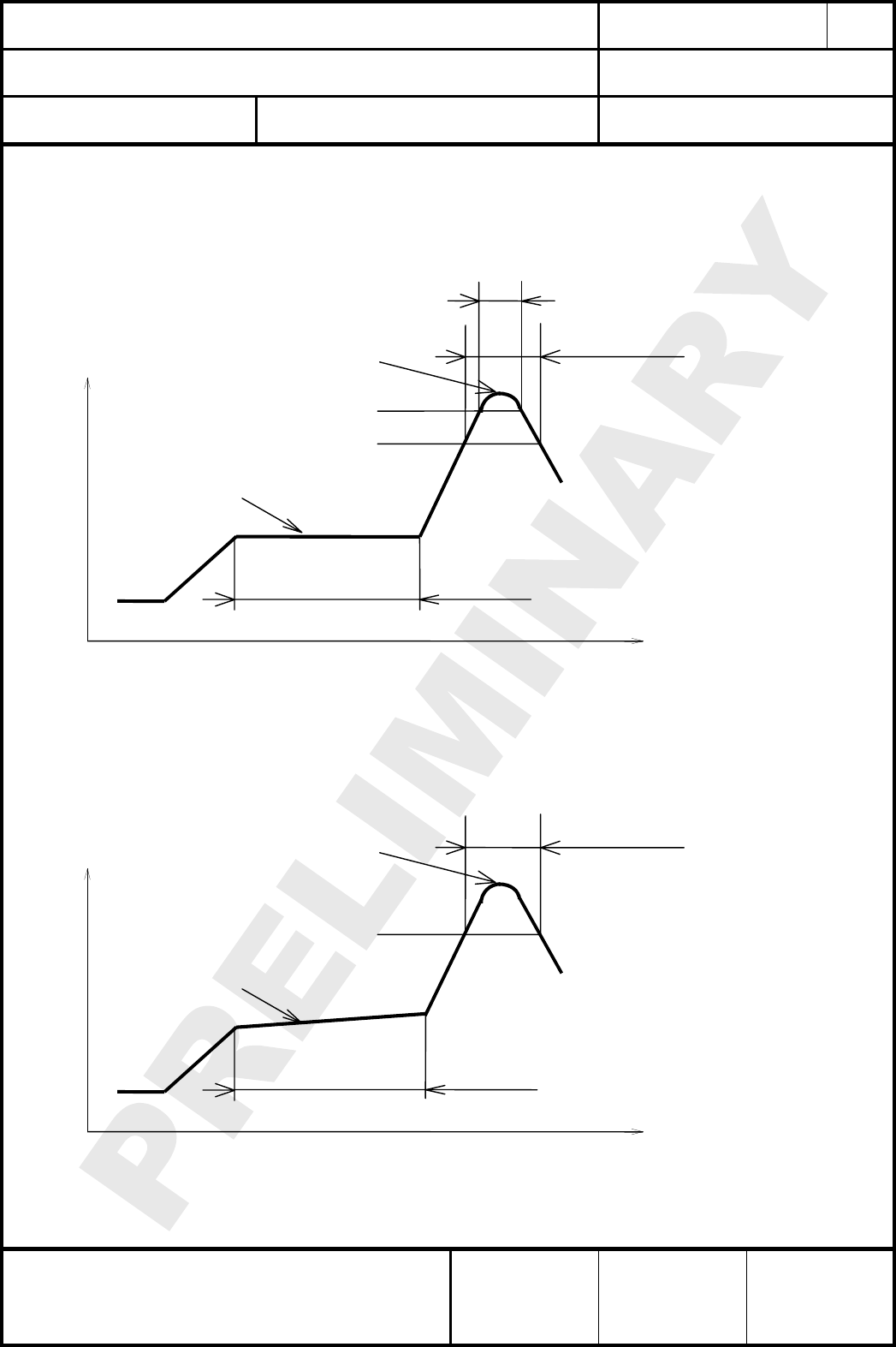
16. SOLDERING TEMPERATURE-TIME PROFILE (FOR REFLOW SOLDERING)
Temperatur-Zeit Profil für die Reflowlötung
16.1. FOR LEAD SOLDER
Recommended temp. profile
for reflow soldering
Tem
p
.
[
°C
]
Time [s]
235°C max.
220 ±5°C
200°C
150 ±10°C
90 ±30s
10
±
1s
30 +20/-10s
16.2. FOR LEAD FREE SOLDER
Our used temp. profile
for reflow soldering
Temp.[°C]
Time [s]
230°C -250°C max.
220°C
150°C – 190°C
90 ±30s
30 +20/-10s
Reflow permissible cycle: 2
Opposite side reflow is prohibited due to module weight.
CLASSIFICATION
Einstufung PRODUCT SPECIFICATION
Produktspezifikation No.
DS-ETRX2-PA-2400-102 REV.
D
SUBJECT
Thema MODEM FOR IEEE802.15.4 (ZIGBEE)
“ZigBee” Modem“ (IEEE802.15.4) PAGE
Seite
19 of 33
CUSTOMER’S CODE
ETRX2-PA PANASONIC’S CODE
ENWC9A13A3EF / ENWC9A16A3EF DATE
Datum 25.10.2007
HIGH FREQUENCY PRODUCTS DIVISION
Module Business
PANASONIC ELECTRONIC DEVICES
(EUROPE) GmbH
APPROVED
genehmigt CHECKED
geprüft DESIGNED
erstellt
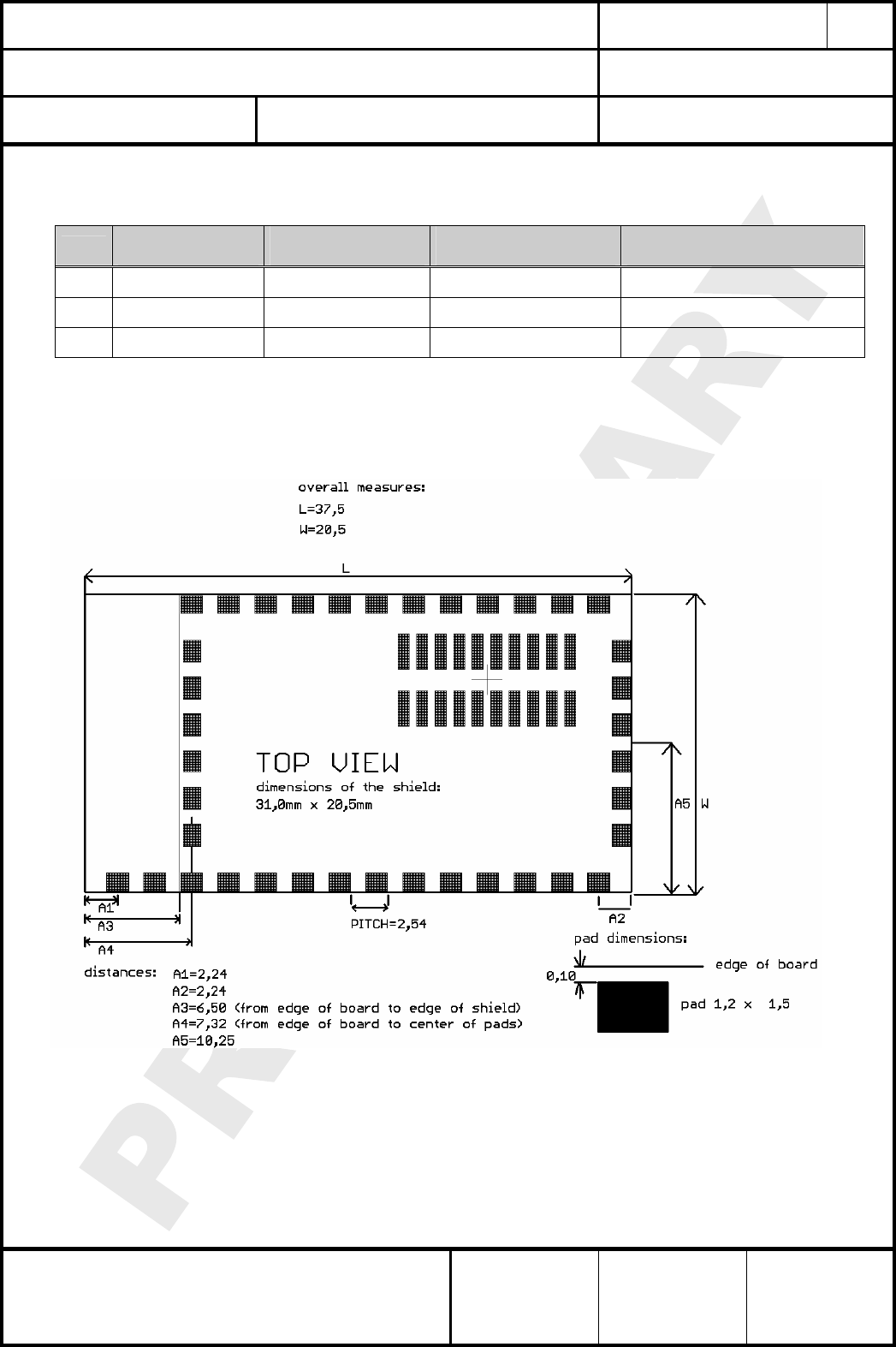
17. MODULE DIMENSIONS
Modulabmessungen
No. Item
Punkt
Dimension
Abmessung
Tolerance
Toleranz
Remark
Bemerkung
1 Width 20.50 ± 0.20
2 Lenght 37.50 ± 0.20
3 Height 2.80 ± 0.10 With case
18. FOOT PRINT OF THE MODULE
Lötpads vom Modul
Dimensions in mm.
CLASSIFICATION
Einstufung PRODUCT SPECIFICATION
Produktspezifikation No.
DS-ETRX2-PA-2400-102 REV.
D
SUBJECT
Thema MODEM FOR IEEE802.15.4 (ZIGBEE)
“ZigBee” Modem“ (IEEE802.15.4) PAGE
Seite
20 of 33
CUSTOMER’S CODE
ETRX2-PA PANASONIC’S CODE
ENWC9A13A3EF / ENWC9A16A3EF DATE
Datum 25.10.2007
HIGH FREQUENCY PRODUCTS DIVISION
Module Business
PANASONIC ELECTRONIC DEVICES
(EUROPE) GmbH
APPROVED
genehmigt CHECKED
geprüft DESIGNED
erstellt
FCC ID: T7VEM250A
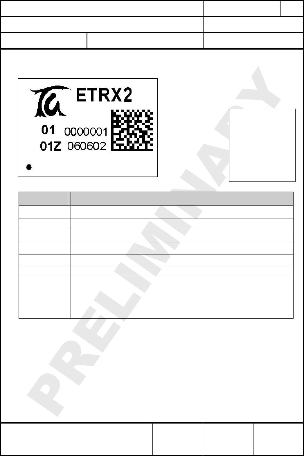
19. LABELING DRAWING
Kennzeichnung des Moduls durch Label
The label dimensions are 13,0mm x 18,5
mm. It is suited for reflow soldering.
-PA
comment:
change ETRX2
to
ETRX2-PA
add CE logo
to larger label
if possible
B
Imprint
Aufdruck
Description
Beschreibung
ETRX2-PA This is the marketing name from Telegesis, the ENW number is only integrated in the 2D
Code and marked with the Z
Date Code Production Date Code in the format YYMMDD, e.g. 060602
01 Indication for software revision for our final test, customer are able to flash there own
software.
01Z Indication for the hardware revision, Z indicates the ES status, will be removed after MP
ready.
0000001 Indication for the serial number.
FCC ID: TBD This is the FCC ID, should be labelled only after FCC approval.
2D-Barcode
Information in the 2D-Barcode are the serial number [7 signs], the ENW-Part-Number [11
signs], identifier for the software release [2 signs], the identifier for the hardware release [2
signs] and the production date code in the format Year-Month-Day [6 signs], separated by a
semicolon.
The IEEE802.15.4 MAC Address [12 characters] are stored in the EM250, therefore it could
not be on the label, but must be stored in the excel sheet to have a reference betweeen MAC
address and serial number.
20. RECOMMENDED LAND PATTERN
Empfohlenes Land Pattern
This part will be included in next revisions.
CLASSIFICATION
Einstufung PRODUCT SPECIFICATION
Produktspezifikation No.
DS-ETRX2-PA-2400-102 REV.
D
SUBJECT
Thema MODEM FOR IEEE802.15.4 (ZIGBEE)
“ZigBee” Modem“ (IEEE802.15.4) PAGE
Seite
21 of 33
CUSTOMER’S CODE
ETRX2-PA PANASONIC’S CODE
ENWC9A13A3EF / ENWC9A16A3EF DATE
Datum 25.10.2007
HIGH FREQUENCY PRODUCTS DIVISION
Module Business
PANASONIC ELECTRONIC DEVICES
(EUROPE) GmbH
APPROVED
genehmigt CHECKED
geprüft DESIGNED
erstellt
21. SOFTWARE
Software
21.1. SOFTWARE DECLARATION
With the signature on the front page, customer clearly understand and agreed that
the software, which is included in the module is only for testing purpose and
Panasonic deny any responsibility for product liability, related to software matters.
21.2. SOFTWARE TOOLS
In order to develop code and ZigBee® networks the Ember Insight Desktop Development
Environment is required. This environment works with the preceeding EM2420, the EM250
and the EM260. For code development it comprises the Integrated Development
Environment (IDE) named xIDE based on eclipse 3.1.0 for editing, compiling and
debugging of C–applications. In addition network visualization and debugging tools are
included.
For programming the Ember Insight Adapter is required. This adaptor has to be linked to
the computer where the Ember software tools are installed on. Before connecting ETRX2-
PA to the Ember Insight Adaptor study the latest Ember Insight Adaptor documentation.
During programming or debugging the pins of ETRX2-PA have to be connected to the
signals on the debug connector of the Ember Insight adaptor as shown in the table below.
It is recommended to provide access to the programming pins of ETRX2-PA on the printed
circuit board in order to allow software updates.
ETRX2-PA pin ETRX2-PA signal name Insight Adapter signal name
various ground ground
7(10) (1) VBAT 3.0Vdc
24(14) RESET RSTB
16 SIF_CLK SIF_CLK
17 SIF_MISO SIF_MISO
18 SIF_MOSI SIF_MOSI
19 SIF_LOADB SIF_LOADB
as packet trace interface (PTI) also connect the following signals:
9(4) GPIO4 GPIO4
10(5) GPIO5 GPIO5
Note:
(1) Only if the Ember Insight Adaptor is set to powering the target device ETRX2-PA.
The pin numbers in brackets () are the related pins of the pin/header connector X5,
which is only mounted for special plug versions.
CLASSIFICATION
Einstufung PRODUCT SPECIFICATION
Produktspezifikation No.
DS-ETRX2-PA-2400-102 REV.
D
SUBJECT
Thema MODEM FOR IEEE802.15.4 (ZIGBEE)
“ZigBee” Modem“ (IEEE802.15.4) PAGE
Seite
22 of 33
CUSTOMER’S CODE
ETRX2-PA PANASONIC’S CODE
ENWC9A13A3EF / ENWC9A16A3EF DATE
Datum 25.10.2007
HIGH FREQUENCY PRODUCTS DIVISION
Module Business
PANASONIC ELECTRONIC DEVICES
(EUROPE) GmbH
APPROVED
genehmigt CHECKED
geprüft DESIGNED
erstellt
21.3. EMBER ZIGBEE® STACK
EmberZNet (currently available in versions 2.5.4 and 3.0.1) is the ZigBee® stack provided
with EM250. It supports as networking topologies true mesh, star and cluster networks.
The ZigBee® devices ZigBee® Coordinator, ZigBee® Router and ZigBee® End Device
are supported.
For the ease of application programming EmberZNet is controlled by the application over
API commands. Direct ZigBee® APS layer APIs are provided for applications that require
low level ZigBee® control.
According to [1] each ZigBee® device has a unique address. This address is provided
by Ember Inc. with the EM250.
For more information on the items above see the website of Ember Inc. (www.ember.com)
and the documentation included in the Ember Insight Desktop package as part of the
Ember development kits.
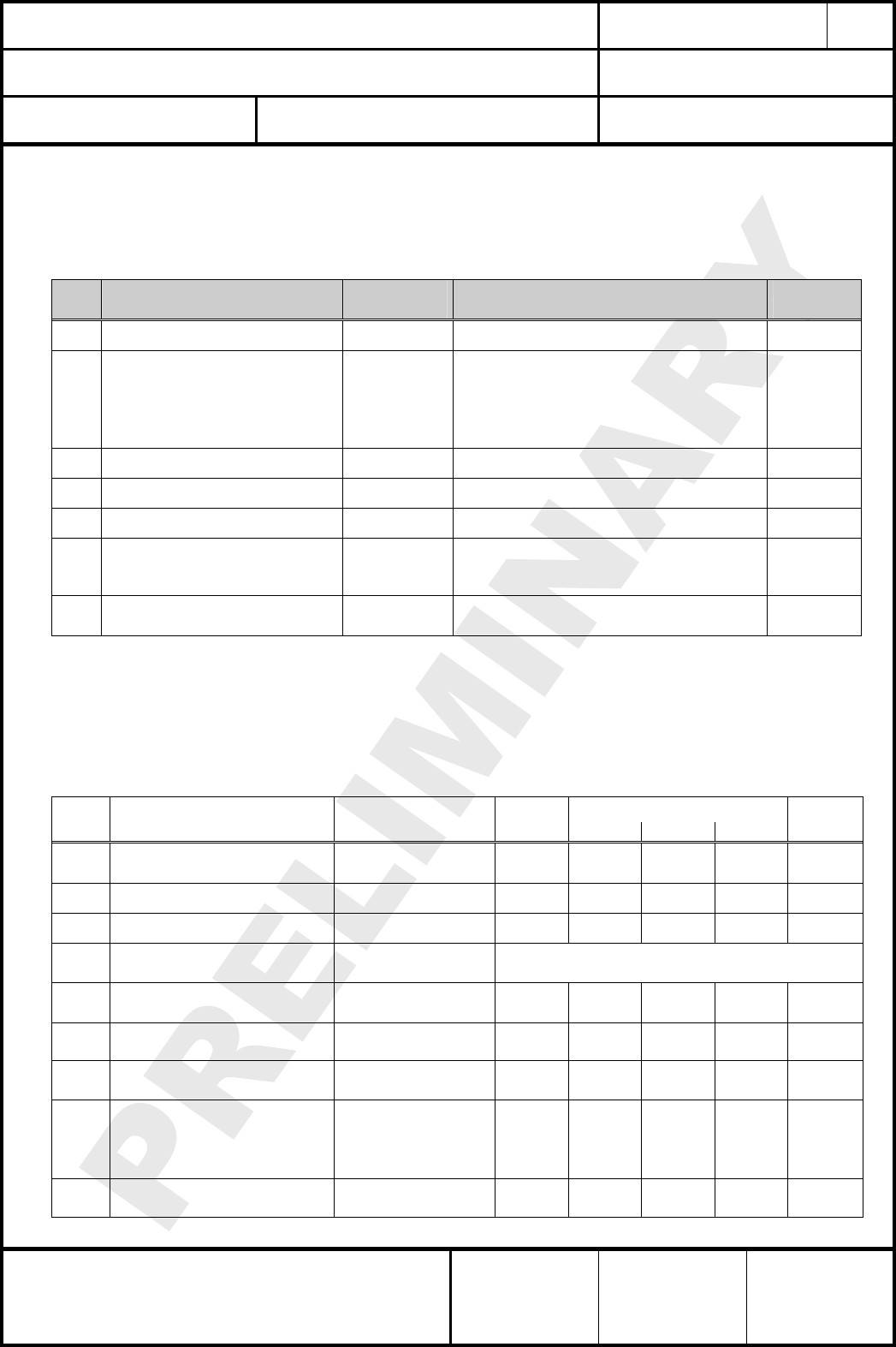
22. RELIABILITY TESTS
Zuverlässigkeitstests
The measurement should be done after exposed to room temperature and humidity for 1hour.
Die Messungen sollten erst nach einer Stunde Lagerung unter normalen Bedingungen erfolgen.
No. Item
Punkt
Limit
Grenzwerte
Condition
Bedingung
1 Vibration test Electrical parameter should be
in specification
a) Freq.:10~50Hz,Amplitude:1.5mm
a) 20min. / cycle,1hrs. each of XYZ axis
b) Freq.:30~100Hz, 6G
b) 20min. / cycle,1hrs. each of XYZ axis
2 Shock test the same as the above Dropped onto hard wood from height of 50cm for
3 times
3 Heat cycle test the same as the above -40°C for 30min. and +85°C for 30min.;
each temperature 300 cycles
4 Moisture test the same as the above +60°C, 90% RH, 300h
5 Low temp. test the same as the above -40°C, 300h
6 High temp. test the same as the above +85°C, 300h
23. APPLICATION NOTES
Applikationshinweise
23.1. CAUTIONS FOR SAFETY
Sicherheitshinweise
These specifications are intended to preserve the quality assurance of products as
individual components.
Before use, check and evaluate their operation when mounted on your products. Abide by
these specifications, without deviation when using the products.These products may short-

CLASSIFICATION
Einstufung PRODUCT SPECIFICATION
Produktspezifikation No.
DS-ETRX2-PA-2400-102 REV.
D
SUBJECT
Thema MODEM FOR IEEE802.15.4 (ZIGBEE)
“ZigBee” Modem“ (IEEE802.15.4) PAGE
Seite
23 of 33
CUSTOMER’S CODE
ETRX2-PA PANASONIC’S CODE
ENWC9A13A3EF / ENWC9A16A3EF DATE
Datum 25.10.2007
HIGH FREQUENCY PRODUCTS DIVISION
Module Business
PANASONIC ELECTRONIC DEVICES
(EUROPE) GmbH
APPROVED
genehmigt CHECKED
geprüft DESIGNED
erstellt
circuit. If electrical shocks, smoke, fire, and/or accidents involving human life are
anticipated when a short circuit occurs, then at least, provide the following failsafe
functions, as a minimum.
(1) Ensure the safety of the whole system by installing a protection circuit and a protection
device.
(2) Ensure the safety of the whole system by installing a redundant circuit or another
system to prevent a single fault causing an unsafe status.
23.2. DESIGN ENGINEERING NOTES
Designhinweise
(1) Heat is the major cause of shortening the life of these products. Avoid assembly and
use of the target equipment in conditions where the products' temperature may exceed
the maximum allowable.
(2) Failure to do so may result in degrading of the product’s functions and damage to the
product.
(3) If pulses or other transient loads (a large load applied in a short time) are applied to
the products, then before use, check and evaluate their operation when assembled on
your products.
(4) Carefully position the products so that their heat will not burn into printed circuit boards
or affect the other components that are susceptible to heat.
(5) Carefully locate these products so that their temperatures will not increase due to the
effects of heat generated by neighbouring components.
(6) If a vinyl-covered wire comes into contact with the products, then the cover will melt
and generate toxic gas, damaging the insulation. Never allow contact between the
cover and these products to occur.
(7) These products are intended for general purpose and standard use in general
electronic equipment, such as home appliances, office equipment, information and
communication equipment.
(8) These products are not intended for other uses, other than under the special
conditions shown below. Before using these products under such special conditions,
check their performance and reliability under the said special conditions carefully to
determine whether or not they can be used in such a manner.
(9) In liquid, such as water, salt water, oil, alkali, or organic solvent, or in places where
liquid may splash.
(10) In direct sunlight, outdoors, or in a dusty environment without a protective case.
(11) In an environment where condensation occurs.
(12) In an environment with a high concentration of harmful gas (e.g. salty air, HCl, Cl2,
SO2, H2S, NH3, and NOx)
(13) If an abnormal voltage is applied due to a problem occurring in other components or
circuits, replace these products with new products because they may not be able to
provide normal performance even if their electronic characteristics and appearances
appear satisfactory.
(14) Mechanic stress during assembly on board and operation has to be avoived.
(15) Pressing on parts of the metal cover or fastening objects to the metal cover is not
allowed.
CLASSIFICATION
Einstufung PRODUCT SPECIFICATION
Produktspezifikation No.
DS-ETRX2-PA-2400-102 REV.
D
SUBJECT
Thema MODEM FOR IEEE802.15.4 (ZIGBEE)
“ZigBee” Modem“ (IEEE802.15.4) PAGE
Seite
24 of 33
CUSTOMER’S CODE
ETRX2-PA PANASONIC’S CODE
ENWC9A13A3EF / ENWC9A16A3EF DATE
Datum 25.10.2007
HIGH FREQUENCY PRODUCTS DIVISION
Module Business
PANASONIC ELECTRONIC DEVICES
(EUROPE) GmbH
APPROVED
genehmigt CHECKED
geprüft DESIGNED
erstellt
23.3. STORAGE CONDITIONS
Lagerbedingungen
The module may not be stressed mechanically during storage.
Do not store these products in the following conditions or the performance characteristics
of the product, such as RF performance will be adversely affected:
(1) Storage in salty air or in an environment with a high concentration of corrosive gas,
such as Cl2, H2S, NH3, SO2, or NOX
(2) Storage in direct sunlight
(3) Storage in an environment where the temperature may be outside the range of 5°C to
35°C range, or where the humidity may be outside the 45 to 85% range.
(4) Storage (prior to integration into your end product) of the products for more than one
year after the date of delivery at your company if all the above conditions (1) to (3)
have been avoided.
CLASSIFICATION
Einstufung PRODUCT SPECIFICATION
Produktspezifikation No.
DS-ETRX2-PA-2400-102 REV.
D
SUBJECT
Thema MODEM FOR IEEE802.15.4 (ZIGBEE)
“ZigBee” Modem“ (IEEE802.15.4) PAGE
Seite
25 of 33
CUSTOMER’S CODE
ETRX2-PA PANASONIC’S CODE
ENWC9A13A3EF / ENWC9A16A3EF DATE
Datum 25.10.2007
HIGH FREQUENCY PRODUCTS DIVISION
Module Business
PANASONIC ELECTRONIC DEVICES
(EUROPE) GmbH
APPROVED
genehmigt CHECKED
geprüft DESIGNED
erstellt
24. PACKAGING
Verpackung
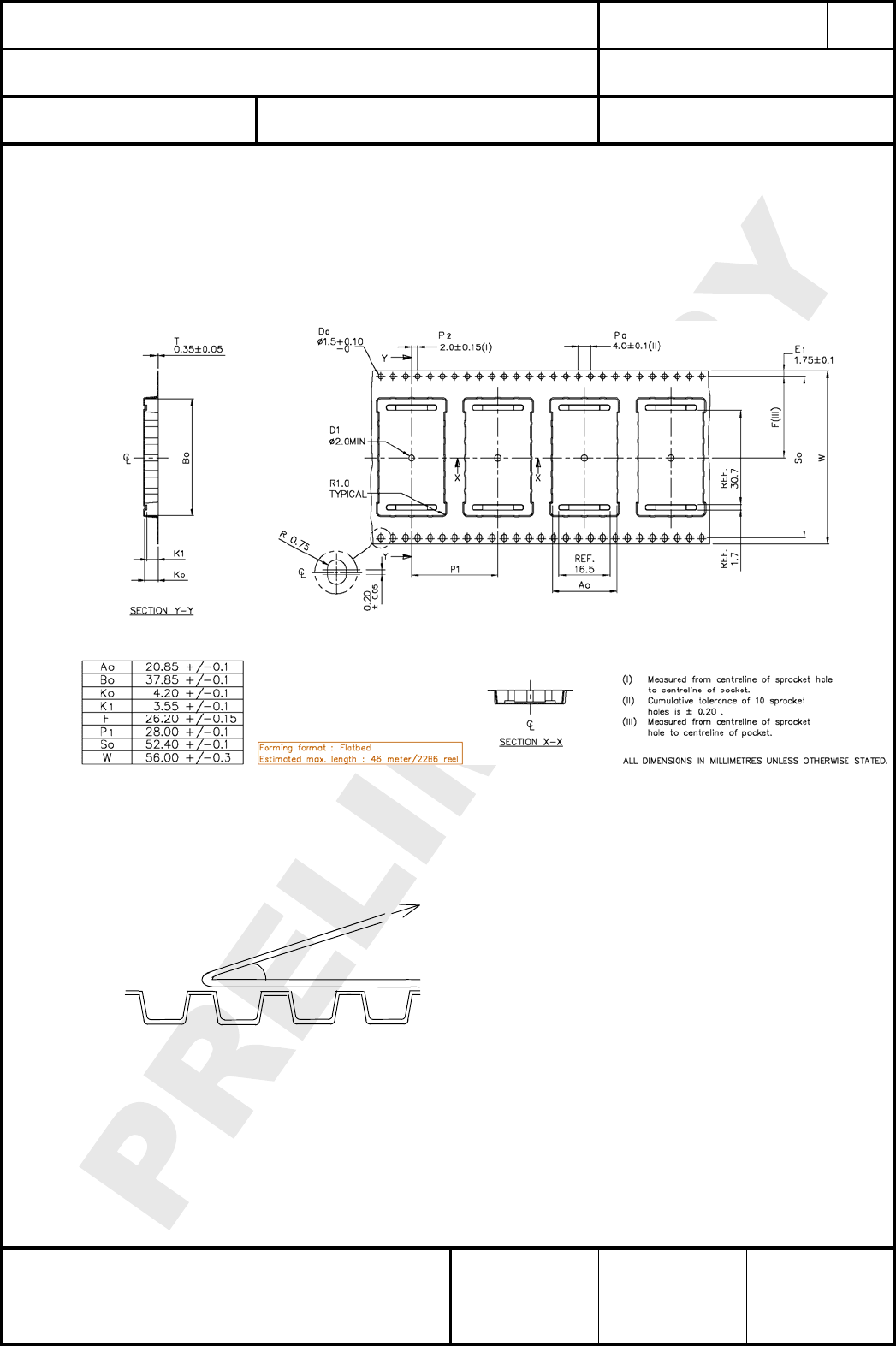
24.1. EMBOSSED TAPE / BLISTERGURT
(1) Dimension of the tape / Abmessungen des Gurtes (EIAJ-tbd)
(2) Cover tape reel strength / Abzugskräfte Blistergurt Deckfolie
Force direction
Speed = 300mm/min.
Cover tape reel strength
=0.098~0.68N (10~70g)
θ= 10deg
CLASSIFICATION
Einstufung PRODUCT SPECIFICATION
Produktspezifikation No.
DS-ETRX2-PA-2400-102 REV.
D
SUBJECT
Thema MODEM FOR IEEE802.15.4 (ZIGBEE)
“ZigBee” Modem“ (IEEE802.15.4) PAGE
Seite
26 of 33
CUSTOMER’S CODE
ETRX2-PA PANASONIC’S CODE
ENWC9A13A3EF / ENWC9A16A3EF DATE
Datum 25.10.2007
HIGH FREQUENCY PRODUCTS DIVISION
Module Business
PANASONIC ELECTRONIC DEVICES
(EUROPE) GmbH
APPROVED
genehmigt CHECKED
geprüft DESIGNED
erstellt
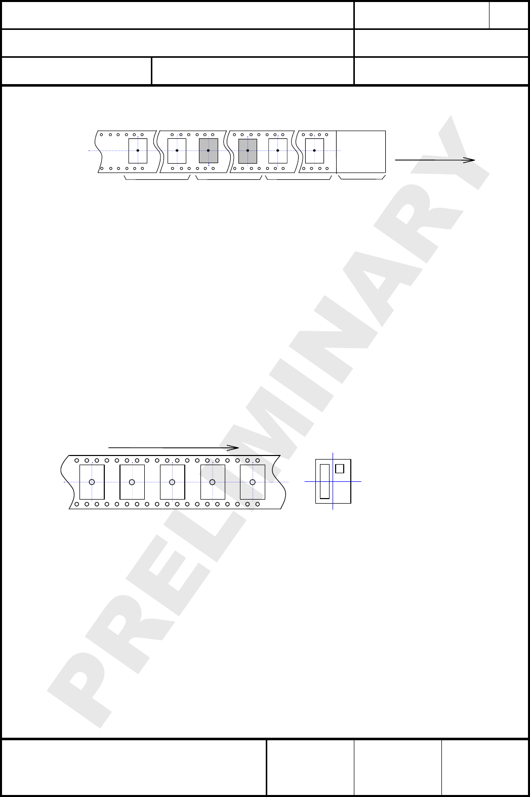
(3) Empty hollow / leere Taschen
Empty hollow more
than 10 pitch
Mehr als 10 leere
Component
packed area
Modulbereic
Empty hollow more
than 10pitch
Mehr als 10 leere
Top cover tape
more than 200mm
Deckfolie groesser als
Direction of feed
Vorschubrichtun
Empty hollow in component packed area shall be less than two per reel and those hollows
shall not be consecutive.
Es dürfen minimal 2 leere Taschen im Bereich der Komponenten vorhanden sein, diese
dürfen aber nicht aufeinander folgen.
24.2. COMPONENT DIRECTION
Komponentenanordnung
Top cover tape shall not be found on reel holes and shall not stick out from reel.
Deckfolien darf nicht durch die Löcher der Spule und nicht außerhalb der Spule geführt
werden.
1
6 7
12
(
to
p
view
)
Component direction
Komponentenrichtung
Part No.
Tape running direction
Laufrichtung des Bandes
Figure 1
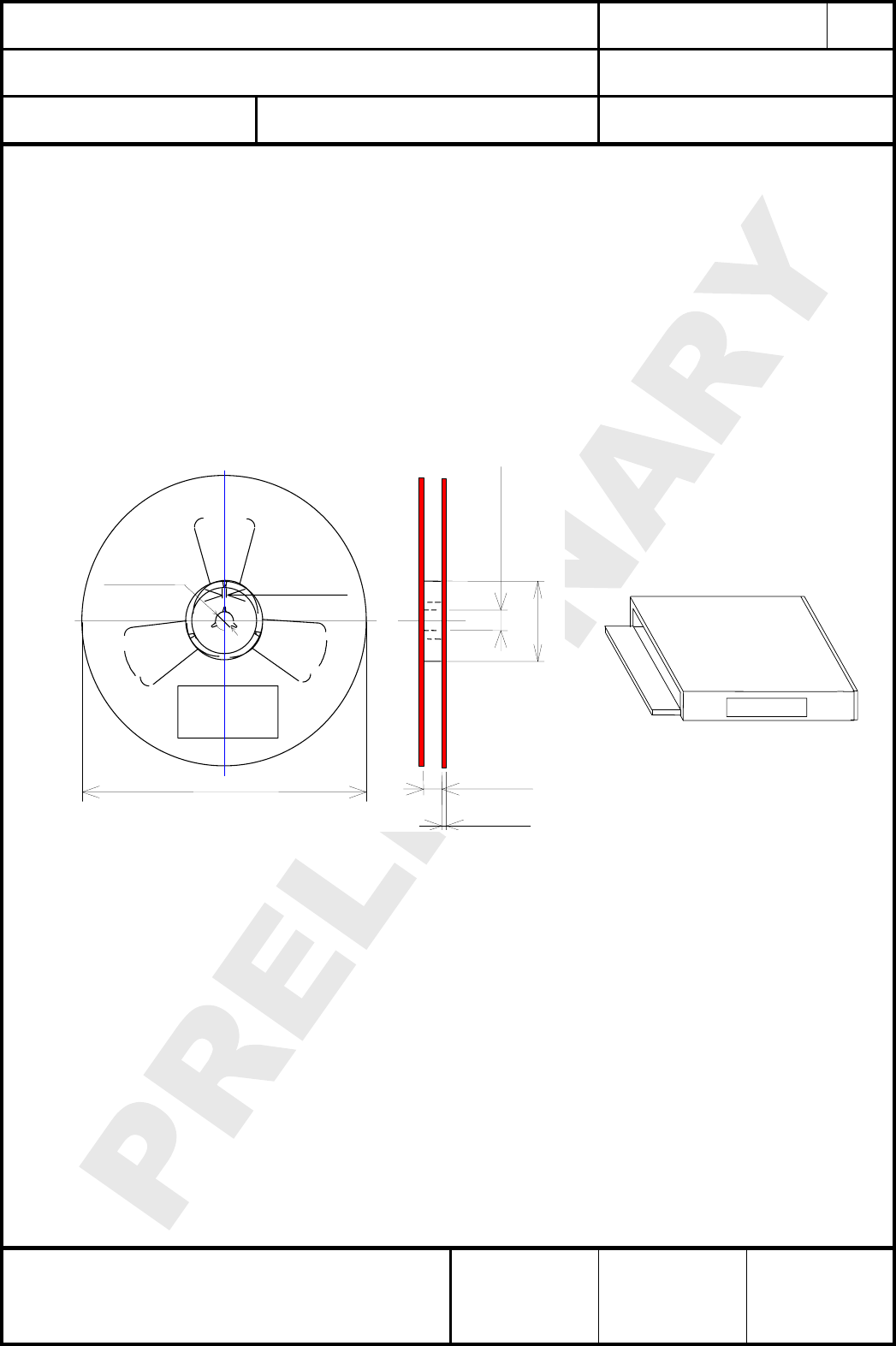
24.3. REEL DIMENSION
Abmaße der Rolle
(1) Quantity per reel : 400 pieces
Anzahl pro Rolle : 400 Stück
(2) Marking : Customer’s part No. / Quantity / Lot No. and Our part# with bar-code
shall be on the reel.
Kennzeichnung : Kundennummer / Anzahl / Losnummer und unsere
Komponentennummer als Barcode wird auf die Rolle gedruckt
Refer to figure 2
Bezugnehmend zur Zeichnung 2
CLASSIFICATION
Einstufung PRODUCT SPECIFICATION
Produktspezifikation No.
DS-ETRX2-PA-2400-102 REV.
D
SUBJECT
Thema MODEM FOR IEEE802.15.4 (ZIGBEE)
“ZigBee” Modem“ (IEEE802.15.4) PAGE
Seite
27 of 33
CUSTOMER’S CODE
ETRX2-PA PANASONIC’S CODE
ENWC9A13A3EF / ENWC9A16A3EF DATE
Datum 25.10.2007
HIGH FREQUENCY PRODUCTS DIVISION
Module Business
PANASONIC ELECTRONIC DEVICES
(EUROPE) GmbH
APPROVED
genehmigt CHECKED
geprüft DESIGNED
erstellt
24.4. PACKAGE
Umverpackung
(1) Package box : 1 or 2 reel (depends on quantity)
Paketbox.: 1 oder 2 Rollen (abhängig von der Liefermenge)
(2) Marking : Customer’s part No. / Quantity / Lot No. and Our part#
with bar-code shall be on the package box.
Kennzeichnung : Kundennummer / Anzahl / Losnummer und unsere
Komponentennummer als Barcode wird auf die
Verpackung gedruckt
Refer to figure 2 and 3
Bezugnehmend zur Zeichnung 2 und 3
φ13 +/-1 2 +/-0.5
φ330
Marking
33.5 +/-1.0
2.0 +/-0.2
φ13 +/-0.5
φ80 +/-2
Figure 2
Markin
g
Figure 3
CLASSIFICATION
Einstufung PRODUCT SPECIFICATION
Produktspezifikation No.
DS-ETRX2-PA-2400-102 REV.
D
SUBJECT
Thema MODEM FOR IEEE802.15.4 (ZIGBEE)
“ZigBee” Modem“ (IEEE802.15.4) PAGE
Seite
28 of 33
CUSTOMER’S CODE
ETRX2-PA PANASONIC’S CODE
ENWC9A13A3EF / ENWC9A16A3EF DATE
Datum 25.10.2007
HIGH FREQUENCY PRODUCTS DIVISION
Module Business
PANASONIC ELECTRONIC DEVICES
(EUROPE) GmbH
APPROVED
genehmigt CHECKED
geprüft DESIGNED
erstellt
25. ORDERING INFORMATION
Bestellinformationen
Ordering part number Description MOQ Fehler!
Verweisquelle konnte nicht
gefunden werden.
ENWCZA13A3EF Fehler!
Verweisquelle konnte nicht
gefunden werden.
Engineering Sample ETRX2-PA with Ember IC EM250
ETRX2 with integrated ceramic antenna 1
ENWCZA14N2EF Fehler!
Verweisquelle konnte nicht
gefunden werden.
Engineering Sample ETRX2-PA with Ember IC EM250
ETRX2 with U.FL male socket 1
ENWCZA15N4EF Fehler!
Verweisquelle konnte nicht
gefunden werden.
Engineering Sample ETRX2-PA with Ember IC EM250
ETRX2 with RF out on a SMD pad 1
Notes:
Notes:
(1) Abbreviation for Minimum Order Quantity (MOQ). ).If this module is in mass production the
standard MOQ are 400 pieces, fewer only on customer demand.
(2) As long as the module has engineering status, the ceramic antenna and the U.FL socket are
mounted for all versions.
The “Z” in the ordering part number indicates the engineering sample status. After mass
production the “Z” will be changed to the “9”.

CLASSIFICATION
Einstufung PRODUCT SPECIFICATION
Produktspezifikation No.
DS-ETRX2-PA-2400-102 REV.
D
SUBJECT
Thema MODEM FOR IEEE802.15.4 (ZIGBEE)
“ZigBee” Modem“ (IEEE802.15.4) PAGE
Seite
29 of 33
CUSTOMER’S CODE
ETRX2-PA PANASONIC’S CODE
ENWC9A13A3EF / ENWC9A16A3EF DATE
Datum 25.10.2007
HIGH FREQUENCY PRODUCTS DIVISION
Module Business
PANASONIC ELECTRONIC DEVICES
(EUROPE) GmbH
APPROVED
genehmigt CHECKED
geprüft DESIGNED
erstellt
26. ROHS DECLARATION
RoHS-Erklärung
Declaration of environmental compatibility for supplied products:
Hereby we declare to our best present knowledge based on declaration of our suppliers that this
product do not contain by now the following substances which are banned by Directive
2002/95/EC (RoHS) or if contain a maximum concentration of 0,1% by weight in homogeneous
materials for
• Lead and lead compounds
• Mercury and mercury compounds
• Chromium (VI)
• PBB (polybrominated biphenyl) category
• PBDE (polybrominated biphenyl ether) category
And a maximum concentration of 0,01% by weight in homogeneous materials for
• Cadmium and cadmium compounds
27. DATA SHEET STATUS
Datenblatt Status
This data sheet contains data from the PRELIMINARY specification. Supplementary data will be
published at a later date. Panasonic Electronic Devices (Europe) GmbH reserves the right to
change the specification without notice, in order to improve the design and supply the best
possible product.
Please consult the most recently issued data sheet before initiating or completing a design.
CLASSIFICATION
Einstufung PRODUCT SPECIFICATION
Produktspezifikation No.
DS-ETRX2-PA-2400-102 REV.
D
SUBJECT
Thema MODEM FOR IEEE802.15.4 (ZIGBEE)
“ZigBee” Modem“ (IEEE802.15.4) PAGE
Seite
30 of 33
CUSTOMER’S CODE
ETRX2-PA PANASONIC’S CODE
ENWC9A13A3EF / ENWC9A16A3EF DATE
Datum 25.10.2007
HIGH FREQUENCY PRODUCTS DIVISION
Module Business
PANASONIC ELECTRONIC DEVICES
(EUROPE) GmbH
APPROVED
genehmigt CHECKED
geprüft DESIGNED
erstellt
28. REGULATORY INFORMATION
28.1. FCC NOTICE
The device ETRX2-PA, including the ceramic antenna (ENWC9A05A3E) and the
approved antennas, listed in Item 28.5, complies with Part 15 of the FCC Rules. The
device meets the requirements for modular transmitter approval as detailed in FCC public
Notice DA00-1407.transmitter
Operation is subject to the following two conditions: (1) This device may not cause harmful
interference, and (2) This device must accept any interference received, including
interference that may cause undesired operation.
28.2. CAUTION
The FCC requires the user to be notified that any changes or modifications made to this
device that are not expressly approved by Panasonic Electronic Devices Europe GmbH
may void the user's authority to operate the equipment.
This equipment has been tested and found to comply with the limits for a Class B digital
device, pursuant to Part 15 of the FCC Rules. These limits are designed to provide
reasonable protection against harmful interference in a residential installation. This
equipment generates, uses and can radiate radio frequency energy and, if not installed
and used in accordance with the instructions, may cause harmful interference to radio
communications. However, there is no guarantee that interference will not occur in a
particular installation. If this equipment does cause harmful interference to radio or
television reception, which can be determined by turning the equipment off and on, the
user is encouraged to try to correct the interference by one or more of the following
measures:
• Reorient or relocate the receiving antenna.
• Increase the separation between the equipment and receiver.
• Connect the equipment into an outlet on a circuit different from that to which the
receiver is connected.
• Consult the dealer or an experienced radio/TV technician for help
28.3. LABELING REQUIREMENTS
The Original Equipment Manufacturer (OEM) must ensure that FCC labeling requirements
are met. This includes a clearly visible label on the outside of the OEM enclosure
specifying the appropriate Panasonic FCC identifier for this product as well as the FCC
Notice above. The FCC identifier is T7VEM250B. This FCC identifier is only valid for the
part number ENWCZA13A3EF (ETRX2-PA with mounted ceramic antenna) or follows the
OEM antenna installation instructions in Item 28.4. For details, please see the chapter 25.
Ordering Information.
The Final Device of an OEM as Composite Device:
A composite device is subject to two or more technical rule parts and requires testing and
labelling appropriately for each of the respective component rule parts. However, as a
CLASSIFICATION
Einstufung PRODUCT SPECIFICATION
Produktspezifikation No.
DS-ETRX2-PA-2400-102 REV.
D
SUBJECT
Thema MODEM FOR IEEE802.15.4 (ZIGBEE)
“ZigBee” Modem“ (IEEE802.15.4) PAGE
Seite
31 of 33
CUSTOMER’S CODE
ETRX2-PA PANASONIC’S CODE
ENWC9A13A3EF / ENWC9A16A3EF DATE
Datum 25.10.2007
HIGH FREQUENCY PRODUCTS DIVISION
Module Business
PANASONIC ELECTRONIC DEVICES
(EUROPE) GmbH
APPROVED
genehmigt CHECKED
geprüft DESIGNED
erstellt
practical rule, only one text or FCC logo need be labelled on a device. As a general rule
the Declaration of Conformity (DoC) text statement is required over any Verification
statement. For composites subject to DoC and Verification, or Certification and
Verification, the labelling requirements for DoC or Certification need only apply. This does
not remove the testing requirement for each individual device in a composite device. For
composite devices subject to DoC and Certification, both the DoC logo and FCC ID (or
FCC IDs when applicable) are required for composite DoC and Certified devices. Devices
subject to DoC for both Part 15 and Part 18 may use only the Part 15 logo.
For information to users, all relevant instructions that pertain to all components of a
composite device are required. For example, Class A or Class B statements in Section
15.105; all warning statements and special instructions as required by Sections 15.21 and
15.27; and all Part 18 applicable instructions / attestations must be clearly stated.
However, realistic variations in editing to clarify the language and structure are permitted
as long as all the relevant points applicable to all of the components are represented.
28.4. ANTENNA INSTALLATION INSTRUCTIONS
The related part number for this device is ENWCZA14N2EF (ETRX2-PA with mounted
connector). For details, please see the chapter 25. Ordering Information. This device will
be tested with an UFL connector from company Hirose and with the antennas listed below.
When integrated in the OEMs product, these fixed antennas require installation preventing
end-users from replacing them with non-approved antennas. Any antenna not in the
following table must be tested to comply with FCC Section 15.203 for unique antenna
connectors and Section 15.247 for emissions. The FCC identifier for this device will be
available, after a first measurement with an approved antenna.
28.5. APPROVED ANTENNA LIST
Note: We are able to qualify your antenna and will add to this list as that process is completed.
Item Part Number Manufacturer Frequency Band Type Gain (dBi)
1 FBKR35068-SM-KR EAD Ltd. 2.4GHz ½ Wave Dipole 2dBi (peak gain)
2 FBTS35024-SM-ST EAD Ltd. 2.4GHz Wire 0dBi (peak gain)
3 FBTS35024-SM-RA EAD Ltd. 2.4GHz Wire 0dBi (peak gain)
CLASSIFICATION
Einstufung PRODUCT SPECIFICATION
Produktspezifikation No.
DS-ETRX2-PA-2400-102 REV.
D
SUBJECT
Thema MODEM FOR IEEE802.15.4 (ZIGBEE)
“ZigBee” Modem“ (IEEE802.15.4) PAGE
Seite
32 of 33
CUSTOMER’S CODE
ETRX2-PA PANASONIC’S CODE
ENWC9A13A3EF / ENWC9A16A3EF DATE
Datum 25.10.2007
HIGH FREQUENCY PRODUCTS DIVISION
Module Business
PANASONIC ELECTRONIC DEVICES
(EUROPE) GmbH
APPROVED
genehmigt CHECKED
geprüft DESIGNED
erstellt
28.6. RF EXPOSURE ETRX2-PA
To comply with FCC RF Exposure requirements, the Original Equipment Manufacturer
(OEM) must ensure that the approved antenna in the previous table must be installed
and/or configured to operate with a separation distance of 20cm or more from all persons
to satisfy RF Exposure compliance.
MPE calculation
P the maximum measured power output is 75mW (18,75 dBm).
G the maximum antenna gain is 2 dBi = numeric gain 1.58.
Smax the maximum permissible exposure is defined in 47 CFR 1.1310 with 1 mW/cm².
R the distance of 20cm from the EUT's transmitting antenna where the exposure
level reaches the maximum permitted level is calculated using the general
equation:
S= P*G / 4R² S = 0.024mW/cm²
The internal / external antenna used for this mobile transmitter must provide a separation
distance of at least 20 cm from all persons and must not be co-located or operating in
conjunction with any other antennas or transmitter.
This device is a Modular Approval to be used for fixed and mobile applications in the 2.4
GHz band and contains functions that are not operational in U.S. Territories.
Portable applications or all application in 900 MHz band will be considered unauthorized
equipment and will be required a separate FCC equipment authorization.
The preceding statement must be included as a CAUTION statement in manuals for
products operating with the approved antennas in the previous table to alert users on FCC
RF Exposure compliance.
Any notification to the end user of installation or removal instructions about the integrated
radio module is not allowed.
The radiated output power of ETRX2-PA with mounted ceramic antenna
(FCC ID: T7VEM250B) is far below the FCC radio frequency exposure limits.
Nevertheless, the ETRX2-PA shall be used in such a manner that the potential for human
contact during normal operation is minimized.
The EUT meets the requirements of FCC section 15.247. End users may not be provided
with the module installation instructions. OEM integrators and end users must be provided
with transmitter operating conditions for satisfying RF exposure compliance.

CLASSIFICATION
Einstufung PRODUCT SPECIFICATION
Produktspezifikation No.
DS-ETRX2-PA-2400-102 REV.
D
SUBJECT
Thema MODEM FOR IEEE802.15.4 (ZIGBEE)
“ZigBee” Modem“ (IEEE802.15.4) PAGE
Seite
33 of 33
CUSTOMER’S CODE
ETRX2-PA PANASONIC’S CODE
ENWC9A13A3EF / ENWC9A16A3EF DATE
Datum 25.10.2007
HIGH FREQUENCY PRODUCTS DIVISION
Module Business
PANASONIC ELECTRONIC DEVICES
(EUROPE) GmbH
APPROVED
genehmigt CHECKED
geprüft DESIGNED
erstellt
29. RELATED DOCUMENTS
Mitgeltende Dokumente
[1] IEEE Standard 802.15.4 –2003 Wireless Medium Access Control (MAC) and Physical
Layer (PHY) Specifications for Low-Rate Wireless Personal Area Networks (LR-WPANs)
[2] Data Sheet EM250, 120-0082-000F March 23, 2006, Ember Inc. (www.ember.com)
[3] Data Sheet U.FL-Series 2004.2 Hirose
Ultra Small Surface Mount Coaxial Connectors - Low Profile 1.9mm or 2.4mm Mated
Height
[4] ETSI EN 300 328 V1.5.1 (2004-03)
Electromagnetic compatibility and Radio spectrum Matters (ERM)
CLASSIFICATION
Einstufung PRODUCT SPECIFICATION
Produktspezifikation No.
DS-ETRX2-PA-2400-102 REV.
D
SUBJECT
Thema MODEM FOR IEEE802.15.4 (ZIGBEE)
“ZigBee” Modem“ (IEEE802.15.4) PAGE
Seite
34 of 33
CUSTOMER’S CODE
ETRX2-PA PANASONIC’S CODE
ENWC9A13A3EF / ENWC9A16A3EF DATE
Datum 25.10.2007
HIGH FREQUENCY PRODUCTS DIVISION
Module Business
PANASONIC ELECTRONIC DEVICES
(EUROPE) GmbH
APPROVED
genehmigt CHECKED
geprüft DESIGNED
erstellt
30. GENERAL INFORMATION
Allgemeine Informationen
© Panasonic Electronic Devices (Europe) GmbH 2006.
All rights reserved.
This product description does not lodge the claim to be complete and free of mistakes.
Please contact the related product manager in every case.
If we deliver samples to the customer, these samples have the status Engineering Samples.
This means, the design of this product is not yet concluded. Engineering Samples may be
partially or fully functional, and there may be differences to be published Data Sheet.
Engineering Samples are not qualified and are not to be used for reliability testing or series
production.
Disclaimer:
Customer acknowledges that samples may deviate from the Data Sheet and may bear defects
due to their status of development and the lack of qualification mentioned above.
Panasonic Electronic Devices (Europe) GmbH rejects any liability or product warranty for
Engineering Samples. In particular, Panasonic Electronic Devices (Europe) GmbH disclaims
liability for damages caused by
• the use of the Engineering Sample other than for Evaluation Purposes, particularly the
installation or integration in an other product to be sold by Customer,
• deviation or lapse in function of Engineering Sample,
• improper use of Engineering Samples.
Panasonic Electronic Devices (Europe) GmbH disclaimes any liability for consequential and
incidental damages.
In case of any questions, please contact your local sales partner or the related product
manager.
31. LIFE SUPPORT POLICY
Politik für Lebenserhaltungssysteme
This Panasonic Electronic Devices (Europe) GmbH product is not designed for use in life
support appliances, devices, or systems where malfunction can reasonably be expected to
result in a significant personal injury to the user, or as a critical component in any life support
device or system whose failure to perform can be reasonably expected to cause the failure of
the life support device or system, or to affect its safety or effectiveness. Customers using or
selling these products for use in such applications do so at their own risk and agree to fully
indemnify Panasonic Electronic Devices (Europe) GmbH for any damages resulting.