Panasonic of North America 11BR1301 Receiver Module User Manual OI Manual SC HTB770 RQT9778 P 121012
Panasonic Corporation of North America Receiver Module OI Manual SC HTB770 RQT9778 P 121012
Contents
- 1. OI Manual_SC-HTB370_RQT9777-P_121011
- 2. OI Manual_SC-HTB770_RQT9778-P_121012
OI Manual_SC-HTB770_RQT9778-P_121012
Owners Manual
Home Theater Audio System
Model No. SC-HTB770
Thank you for purchasing this product.
Please read these instructions carefully before using this product,
and save this manual for future use.
If you have any questions, contact:
U.S.A. and Puerto Rico: 1-800-211-PANA (7262)
Canada: 1-800-561-5505
RQT9778-P
2R QT 97 78
IMPORTANT SAFETY INSTRUCTIONS
Read these operating instructions carefully before using the unit. Follow the safety instructions on the
unit and the applicable safety instructions listed below. Keep these operating instructions handy for
future reference.
1 Read these instructions.
2 Keep these i nstructions.
3 Heed all warnings.
4 Follow all instructions.
5 Do not use this appa ratus near water.
6 Clean onl y with dry cloth.
7 Do no t block any ventilati on open ings. Install in
accordan ce with the man ufacturers instructions.
8 Do not install near any hea t sou rces such as
ra diators, heat registers, stoves, or o ther appar atus
(including amplifiers) that produce heat.
9 Do not de feat the safety purp ose of the polar ized or
gr oun ding-type plug. A polarized pl ug ha s two blad es
with on e wider th an the other.
A grounding- type plug has two bla des and a third
gr oun ding prong. The w ide blade or the third prong
ar e provided for your safety. If the pro vided plug does
not fit i nto your outlet, consult an electrician for
replacement of the obsolete outlet.
10 Protect the power cord from be ing walked on or
pin ched par ticularl y at plu gs, convenience
re ceptacles, and the point wher e th ey exit from the
ap par atus.
11 Only use attachments/accessories specified by the
ma nufacturer.
12 Use only with the cart, stand, tripod,
br acket, or table specified by the
ma nufacturer, or sold with the
appar atus. W hen a ca rt i s u sed, use
cauti on when moving the car t/
appar atus combi nation to avoid injury
from tip- over.
13 Unpl ug this appar atus dur ing lightni ng storms or
whe n unused for long peri ods of time.
14 Refer al l servicing to qualified ser vi ce per sonnel.
Servicin g is required when the appara tus has be en
damaged in any way, such as power-supply cord or
plu g is damage d, liquid has been spilled or objects
have fallen into the a ppa ratus, the app aratus has
been exposed to r ain or moisture , does not oper ate
normally, or has been dropped.
Unit
To reduce the risk of fire, electric shock or product
damage,
Do no t expose thi s u nit to rain, moistur e, dripping or
spla shing.
Do not place objects fi lled with li quids, such as vases,
on this unit.
Use only the recom mended accessories.
Do not remove covers.
Do not repair this unit by yourself. Refer servicing to
quali fied service personnel.
Power cord
Install this unit so that the power cord can be unp lugged
from the socke t ou tl et i mmediately if any pro blem
occurs.
Button-type battery (Lithium battery)
Risk of fire, explosion and burns. Do not disassemble,
heat above 60 oC (140 oF) or incinerate.
WARNING
DO NOT INGEST BATTERY,
CHEMICAL BURN HAZARD
This product contains a coin/button cell battery. If the
coin /button cel l battery is swallo wed, it can cause
severe internal b urns in just 2 hours and can lead to
death. Keep new and used batteries away from
chil dren. If the battery comp artment d oes no t close
securely, stop usin g th e pr oduct and keep it away from
chil dren. If you thin k ba tteries mig ht have b een
swall owed or placed inside a ny part of the body, se ek
immediate medical attention.
If any electro lyte shoul d come into contact wi th your
hand s or clothes, wash it off thor oug hly with water.
If any electro lyte shoul d come into contact wi th your
eyes, never rub the eyes. Rinse e yes thoroug hly with
water, and then con sult a doctor.
<For USA-California only>
This prod uct contains a CR Coin Cell Lithi um Batter y
whi ch contains Perchlorate Materi al special handling
may apply.
See www.dtsc.ca.gov/ha zardouswaste/perchl orate.
RQT9778 3
Unit
Do no t place sou rces of naked fl ames, such as lighted
candles, on this unit.
Placement
To reduce the risk of fire, electric shock or product
damage,
Do no t install or place this unit in a bookcase, built-in
cabinet or in ano ther confin ed space . Ensure this unit
is well ventilated.
Do n ot obstruct this units ventila tio n op eni ngs with
newspapers, tablecloths, cur ta ins, and similar items.
Button-type battery (Lithium battery)
Dan ge r of explosion if battery is incor rectly replaced .
Rep lace only with the type recommended by the
man ufactur er.
Keep out of r each of chil dren.
Inser t with poles ali gne d.
Mishandling of batteries can cause electrolyte leakag e
and may cau se a fir e.
Rem ove the battery i f you do not intend to use the
remote control for a long period of time. Store in a
cool, dark place.
Do not heat or expose to flame.
Do not l eave the battery(ies) in a car e xposed to
di rect sun light for a long per iod of time with doo rs an d
windows closed.
Do not touch the terminals ( and ) with metal
objects.
Do not recharge, di sa ssembl e, r emodel, heat or
thro w i nto fire.
When disposing the batteries, ple ase contact your local
authori ties or dealer and a sk for the correct method of
di sp osal .
CAUTION
THE FOLLOWING APPLIES ONLY IN THE
U.S.A.
FCC Note:
This equipment has been tested and found to comply with
the limits for a Class B digital device, pursuant to Part 15
of the FCC Rules.
These limits are designed to provide reasonable
protection against harmful interference in a residential
installation. This equipment generates, uses and can
radiate radio frequency energy and, if not installed and
used in accordance with the instructions, may cause
harmful interference to radio communications.
However, there is no guarantee that interference will not
occur in a particular installation. If this equipment does
cause harmful interference to radio or television reception,
which can be determined by turning the equipment off and
on, the user is encouraged to try to correct the
interference by one or more of the following measures:
Reorient o r relocate the receiving antenna.
Increase the separation between the equipmen t and
receiver.
Connect the equipment into an outlet on a circuit
different from that to which the receiver is connected.
Consult the dealer or an experienced radio/TV
technician for help.
Any unauthorized changes or modifications to this
equipment would void the users authority to operate this
device.
This device complies with Part 15 of the FCC Rules.
Operation is subject to the following two conditions:
(1) This device may not cause harmful interference, and
(2) this device must accept any interference received,
including interference that may cause undesired
operation.
Responsible Party:
Panasonic Corporation of North America
One Panasonic Way,
Secaucus, NJ 07094
Support Co ntact:
Panasonic Consumer Marketing Compan y of
North America
Telephone No.: 1-800-211-PANA (7262)
THE FOLLOWING APPLIES ONLY IN
CANADA.
This device complies with RSS-GEN, RSS-210 of the IC
Rules. Operation is subject to the following two conditions:
(1) This device may not cause harmful interference,
(2) This device must accept any interference received,
including interference that may cause undesired operation
of the device.
THE FOLLOWING APPLIES IN THE U.S.A.
AND CANADA
This transmitter must not be co-located or operated in
conjunction with any other antenna or transmitter.
This equipment complies with FCC/IC radiation exposure
limits set forth for an uncontrolled environment and meets
the FCC radio frequency (RF) Exposure Guidelines in
Supplemen t C to OET65 and RSS-102 of the IC radio
frequency (RF) Exposure rules. This equipment has very
low levels of RF energy that is deemed to comply without
maximum permissive exposure evalua tion (MPE). But it is
desirable that it should be installed and operated keeping
the radiator at least 20 cm (7 7/8)or more away from
persons body (excluding extremities: hands, wrists, feet
and ankles).
4R QT 97 78
Unit care
Clean this unit with a soft, dry cloth
When di rt is he avy, wr ing a cloth moisten ed in water
tightly to wipe the dirt, and then wipe it with a dry cloth.
When clea ning this unit, use a fine cloth. Do not use
tissues or other materials (towels, etc.) that can fall
apart. Smal l grains m ay get stuck insi de the spe aker
cover.
Neve r u se alcoho l, paint thi nne r o r b enzine to clean this
unit.
Before using chemical ly-tr eated cloth, careful ly read the
instructions that came with the cloth.
About Bluetooth®
Frequency band used
This unit uses the 2.4 GHz frequency band.
Certification of this device
This unit confor ms to frequency restriction s and has
re ceived certi fication based on fre que ncy laws. Th us, a
wire less permit is not necessary.
The action below are punisha ble b y l aw in some
countries:
Takin g apart o r mod ifying the unit.
Rem oving specification i ndi cati ons.
Restrictions of use
Wireless tran smission and/or usage wi th all Blu etooth®
equipped devices is no t g uar anteed.
Al l devices must confor m to standard s set by Bluetooth
SIG, Inc.
Dep en ding on the specifications and setting s o f a
device, it can fail to connect or some operatio ns can be
different.
This unit supports Bluetooth® securi ty featur es. B ut
depe nding on the ope ratin g envi ron ment and/or
settings, this security is possibly not sufficient. Transmit
data wirelessly to this unit with caution.
This unit cannot transmit data to a Bluetooth® device.
Range of use
Use this device at a m aximum range of 10 m (33 ft).
The r ang e can decrease de pe ndi ng on the envi ronment,
obstacles or interferen ce.
Interference from other devices
When other devi ces use the same frequency as this
unit,this unit may operate incorrectly or the sound may
be distorted.
To pre vent in terference from other de vice s:
Keep this unit away from other devices that emit
ra dio fre que ncy interfe rence.
Do not use this system and a wireless LAN device at
the same time. Switch off any wireless LAN device.
Intended usage
This unit is for normal, gene ral u se only.
Do not use this unit near an e qui pme nt o r in an
environmen t tha t is sensitive to radio freq uency
interfere nce (example: a irpo rts, hospitals, l aboratories,
etc).
Manu factured under license from Dolby Laboratories.
Dolby, Pro Logic, and the double-D symbol are trademarks
of Do lby Laboratories.
Manu factured under license under U.S. Patent Nos:
5,95 6,674; 5,974,380; 6,487,535 & other U.S. and
worldwide patents issued & pending.
DTS, the Symbol, & DTS and the Symbol together are
registered trademarks & DTS Digital Surround and the DTS
logos are trademarks of DTS, Inc. Product includes
software.
© DTS, Inc. All Rights Reserved.
HDMI, the HDMI Logo, and High-Definition Multimedia
Interface are trademarks or registered trademarks of HDMI
Licen sing LLC in the United States and other countries.
HDAVI Control is a trademark of Panasonic Corporation.
VIERA Link is a trademark of Panasonic Corporation.
EZ Sync is a trademark of Panasonic Corporation.
The Bluetooth® word mark and logos are owned by the
Bluetooth SIG, Inc. and any use of such marks by
Panasonic Corporation is under license. Other trademarks
and trade names are those of their respective owners.
Panasonic bears no responsibility for data
and/or information that is compromised
during a wireless transmission.
RQT9778 5
Table of contents
IMPORTAN T SAFETY INSTRUCTIONS .......................................................................... 2
Unit care ........................................................................................................................... 4
About Bluetooth®............................................................................................................. 4
Table of contents ............................................................................................................. 5
Before use
Supplied items ................................................................................................................. 6
This unit (SC-HTB770)............................................................................................................. .. 6
Accessories ................. ............ ................................................................................................... 6
Control reference guide .................................................................................................. 7
This unit (Front) ........................................................ ............ ...................................................... 7
This unit (Rear) ................................................................................................................. ......... 8
Remote control....................................................................................................................... .... 9
Getting started
Step 1 S electing the placement method ..................................................................... 10
The speaker system................ ................................................................................................. 11
The active subwoofer .............. ................................................................................................. 11
Wireless interference ............................................................ ................................................... 11
Step 2 Assem bling the speakers ................................................................................. 12
When attaching the speakers to a wall ....................................................... ........... .................. 12
When placing the speakers on a table ....................... ............ ................................. ........... ...... 18
Additional speaker fall prevention measures ............ ....................... ............ ..................... ....... 22
Step 3 Connections ...................................................................................................... 24
Connection with the TV ..................... ....................................................................................... 24
Connection with other devices ................................................................................ .......... ....... 25
Speaker cable connection.............................. ........... ............ ................................................... 26
AC power supply cord connection............................................................... ........... ........... ....... 26
Active subwoofer wireless connection ...................................................... .......... ............ ......... 27
Bluetooth® connection........................................................................... ................................... 27
Operations
Using this unit ................................................................................................................ 28
3D sound ........................................................................................................................ 29
Audio output modes ................................................................................................................. 29
Linked operations with the TV
(VIERA LinkTMHDAVI ControlTM ) .......................................................................... 30
Advanced operations .................................................................................................... 31
Reference
Troubleshooting............................................................................................................. 33
Specifications ................................................................................................................ 35
Indicator illuminat ion..................................................................................................... 37
Limited Warranty
(ONLY FOR U.S.A. AND PUERTO RIC O) ................................................................. 38
Limited Warranty (ONLY FOR CANADA)..................................................................... 39
6R QT 97 78
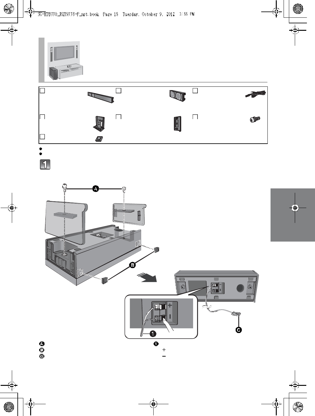
Supplied items
Check the supplied accessories before using this unit.
Product numbers are correct as of December 2012. These may be subject to change.
For U.S.A. and Puerto Rico:
To order accessories, refer to Accessory Purchases (United States and Puerto Rico) on page 38.
For Canada: To order accessories, call the dealer from whom you have made your purchase.
The supplied AC power supply cord is for use with this unit only.
Do not use it with other equipment. Also, do not use cords from other equipment with this unit.
The illustrations shown may differ from your unit.
Operations in this Owners Manual are described mainly with the remote control, but you can
perform the operations on the main unit if the controls are the same.
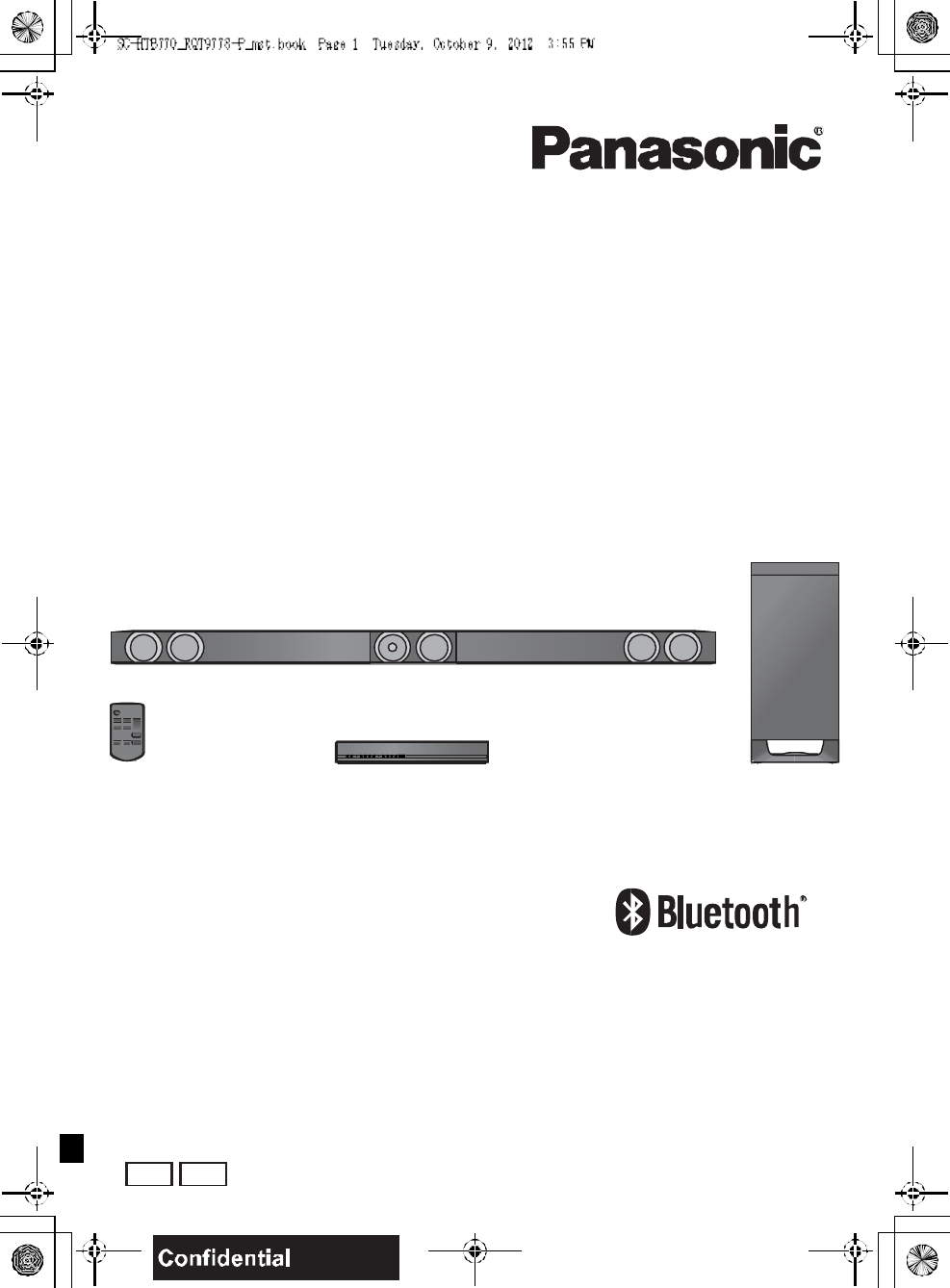
This unit (SC-HTB770)
1 Main unit
(SU-HTB77 0)
1 Active
subwoofer
(SB-HWA770)
1Center speaker
(SB-HTB770)
2 Front speakers
(SB-HTB570)
Accessories
1 Remote control
(with a battery)
(N2QAYC000083)
2 AC power supply
cords
(K2CB2YY00084)
3Speaker cables
(REEX1266A: RED)
(REEX1267A: WHITE)
(REEX12 68: GREEN)
Length: 3 m (9.8 ft)
1Metal bracket
(RML0760A)
6 Screws
(XYN5+J14FJK)
2 Speaker feet
(RKAX0042-K)
2Stand nec ks
(RGK2444)
2Side caps
(RGK2445: R)
(RGK2446: L)
2Leg stands
(RGK2463)
2 Support legs
(RGK2464)
2 Speaker bases
(RGK2465)
(ONLY FOR CANADA)
The enclosed French
Canadian label sheet
corresponds to the
English display on the
remote control and the
top and rear of the main
unit and active
subwoofer.
RQT9778 7
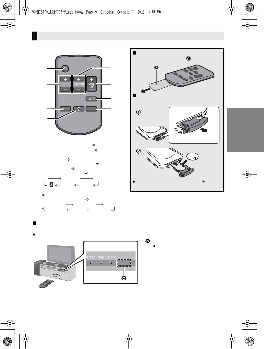
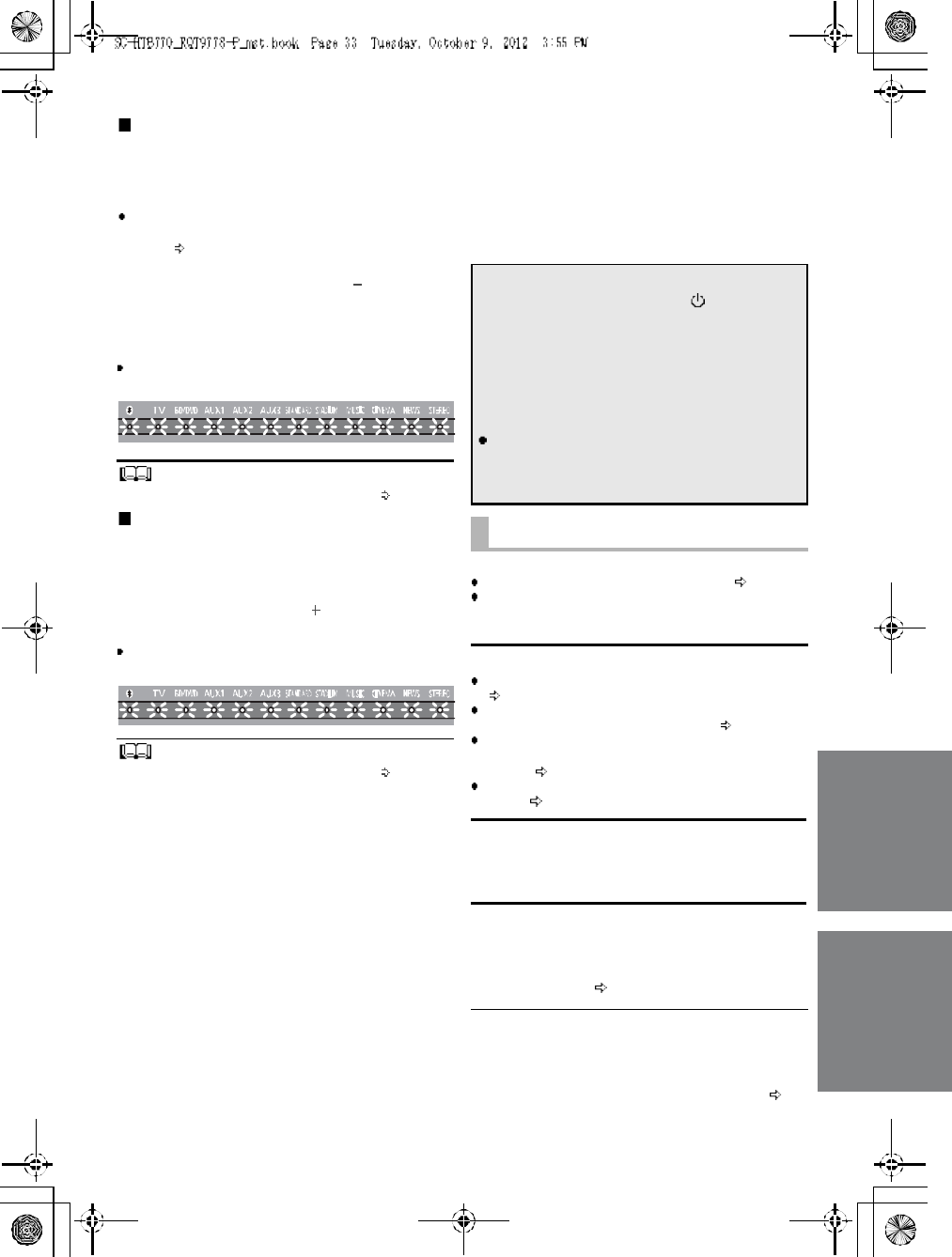
Control reference guide
1Standby/on switch ( /I)
Press to switch the main unit from on to
standby mode or vice versa. In standby mode,
the main unit is still consuming a small amount
of power.
2 Adjust the volume of this unit
3 Select the input source
TVBD/DVDAUX1
AUX3 AUX2
4 Input selector indicators
Bluetooth® indicator
Lights blue when the Bluetooth® device is
the audio source
TV indicator
Lights green when the TV is the audio
source
BD/DVD indicator
Lights amber when the device connected
to the BD/DVD terminal is the audio
source
AUX1 indicator
Lights amber when the device connected
to the AUX1 terminal is the audio source
AUX2 indicator
Lights amber when the device connected
to the AUX2 terminal is the audio source
AUX3 indicator
Lights amber when the device connected
to the AUX3 terminal is the audio source
5Sound mode indicators
STANDARD indicator
Lights when STANDARD is the current
sound mode
STADIUM/Dolby® Digital indicator
Lights when STADIUM is the current
sound mode
MUSIC/DTS indicator
Lights when MUSIC is the current sound
mode
CINEMA/PCM indicator
Lights when CINEMA is the current sound
mode
NEWS indicator
Lights when NEWS is the current sound
mode
STEREO indicator
Lights when STEREO is the current sound
mode
6 Remote control signal sensor ( 9)
7 WIRELESS LINK indicator ( 27)
The indicators will also blink in various conditions ( 37)
To indicate the current audio format, refer to page 31 (Audio format indicator)
This unit (Front)
7
123
4 56
Main unit
Active subwoofer
8R QT 97 78
1 AC IN terminal ( 26)
2 Speaker terminals ( 26)
3 TV terminal ( 24)
4 AUX3 terminal ( 25)
5 USB port (for service use only)
6 AUX2 terminal ( 25)
7 AUX1 terminal ( 25)
8 BD/DVD terminal ( 25)
9 HDMI OUT terminal (ARC compatible) ( 24)
10 Active subwoofer on/off button
The I/D SET button is only used when the main unit is not paired with the active subwoofer ( 35)
This unit (Rear)
A C IN A V IN TV (A RC)
BD/DVDBD/DVDAUX1
(H D M I1)(H D M I2)
AUX2
(H D M I3)
AV O UT
DIGITAL
AUDIO
IN
TV
(O PT 1)
AUX3
(O PT 2)
SPEAKERS/HAUT-PARLEURS
66 6
R
CEN TER
FOR
SER VICE O NL Y
12 3 4 5 6 7 8 9
10
1
RQT9778 9
1 Turn the main unit on or off ( 28)
2 Adjust the dialog effect level ( 28)
3 Adjust the output level of the active subwoofer
(bass sound) ( 28)
4Adjust the volume of this unit (28)
5 Mute the sound ( 28)
6 Select the input source ( 28)
TVBD/DVDAUX1
AUX3 AUX2
7 Select the Bluetooth® device as the source
( 28)
8 Select the sound mode ( 28)
STANDARD STADIUM MUSIC
STEREO NEWSCINEMA
Remote control
Before using for the first time
Remove the insulation sheet .
To replace a button-type battery
Battery type: CR2025 (Lithium battery)
Set the button-type battery with its ( ) mark
facing upward.
Remote control operation range
The remote control signal sensor is located on the main unit.
Use the remote control within the correct operation range.
Remote control signal sensor
Operation range
Distance: Within approx. 7 m
(23 ft) directly in front
Angle: Approx. 30o
left and right
10 R QT 97 78
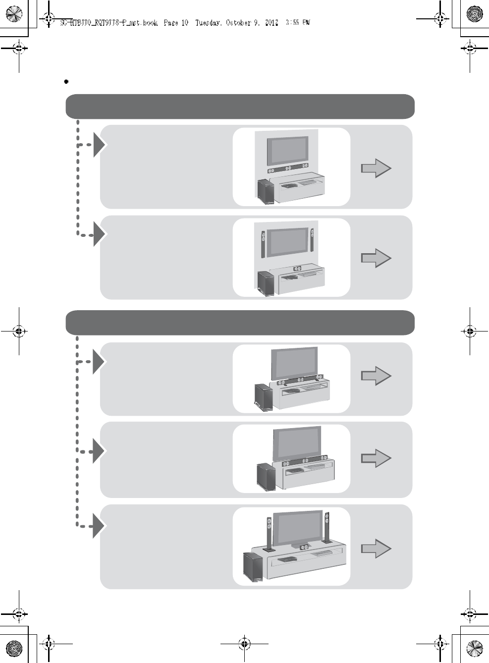
Step 1 Selecting the placement method
Choose a placement method that suits you best.
When attaching the speakers to a wall
When placing the speakers on a table
Place the speakers
horizontally
Page 12
Place the front speakers
vertically
Place the speakers using
the leg stands
Place the front speakers
using the speaker bases
Page 15
Page 18
Page 19
Page 20
Place the speakers
using the support legs
and speaker feet
RQT9778 11
Use a screwdriver ( ) for assembling the speakers.
Do not hold the speakers in one hand to avoid injury, you may drop the speakers when carrying them.
When carrying the active subwoofer
To avoid interference, maintain the following distances between the main unit/active subwoofer
and other electronic devices that use the same radio frequency (2.4 GHz band).
Place the active subwoofer within a few meters of the main unit and in a horizontal position with the top panel faced upward.
Do not use this unit in a metal ca binet.
Placing the active subwoofer too close to the walls and corners can result in excessive bass. Cover walls and windows with
thick curtains.
If irregular coloring occurs on your TV, turn the TV off for about 30 minutes. If it persists, move the speakers further away from
the TV.
Keep magnetized items away. Magnetize d cards, watches, etc., can be damaged if placed too close to the active subwoofer
and the speakers.
Caution
This unit is to be used only as indicated in these instructions. Failure to do so may lead to damage to the
amplifier and/or the speakers, and may result in the risk of fire. Consult a qualified service person if damage
has occurred or if you experience a sudden change in performance.
Do not attempt to attach these speakers to a wall using methods other than those described in this manual.
The speaker system
When attaching the speakers to a wall
The wall or pillar on which the speakers are to be attached should be capable of supporting 33 kg (72.8 lbs) per screw.
Con sultation with a qualified installation specialist is recommended when attaching the speakers to a wall. Improper attachment
may result in damage to the wall and speakers, and personal injury.
When placing the speakers in front of the TV
The speakers may block or interfere with the TVs various sensors (C.A.T.S. (Contrast Automatic Tracking System) sensor,
remo te control sensor, etc.) and the 3D Eyewear transmitters on a 3D compatible TV.
If the stands are being used
Cha nge the height of the stands and/or move the speakers further away from the TV. If the TV still does not function correctly,
try removing the stands.
If the stands are not used
Move the speakers further away from the TV. If the TV still does not function properly, try placing them beside the TV ( 10).
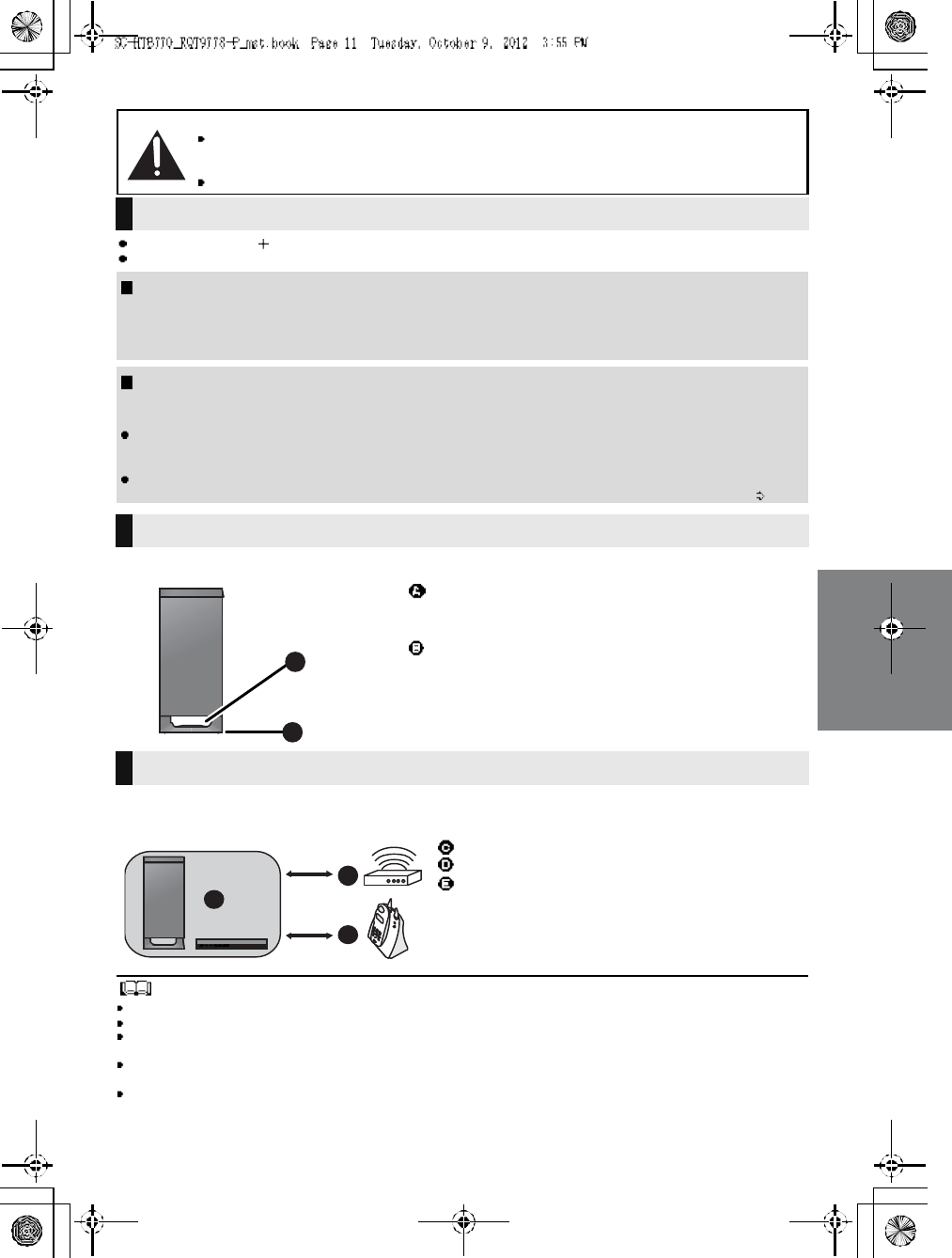
The active subwoofer
Do not hold the active subwoofer from this
opening.
The parts inside may get damaged.
Always hold the bottom of the active subwoofer when
moving it.
Wireless interference
Main unit/active subwoofer
Wireless LAN: approx. 2 m (6 1/2ft)
Cordless phone and other electronic devices:
approx. 2 m (6 1/2ft)
12 R QT 97 78
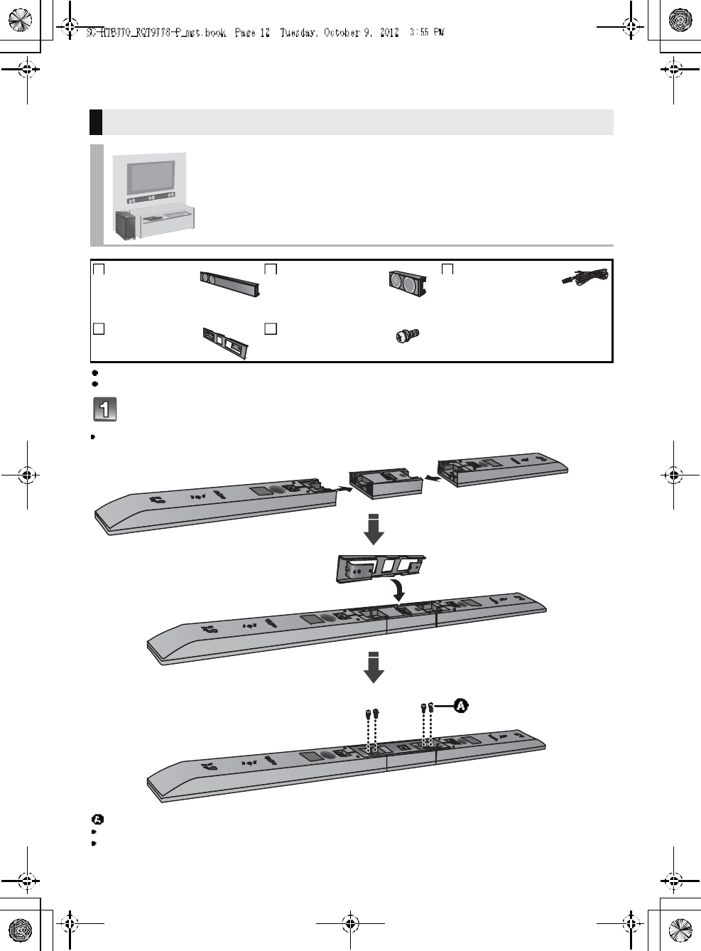
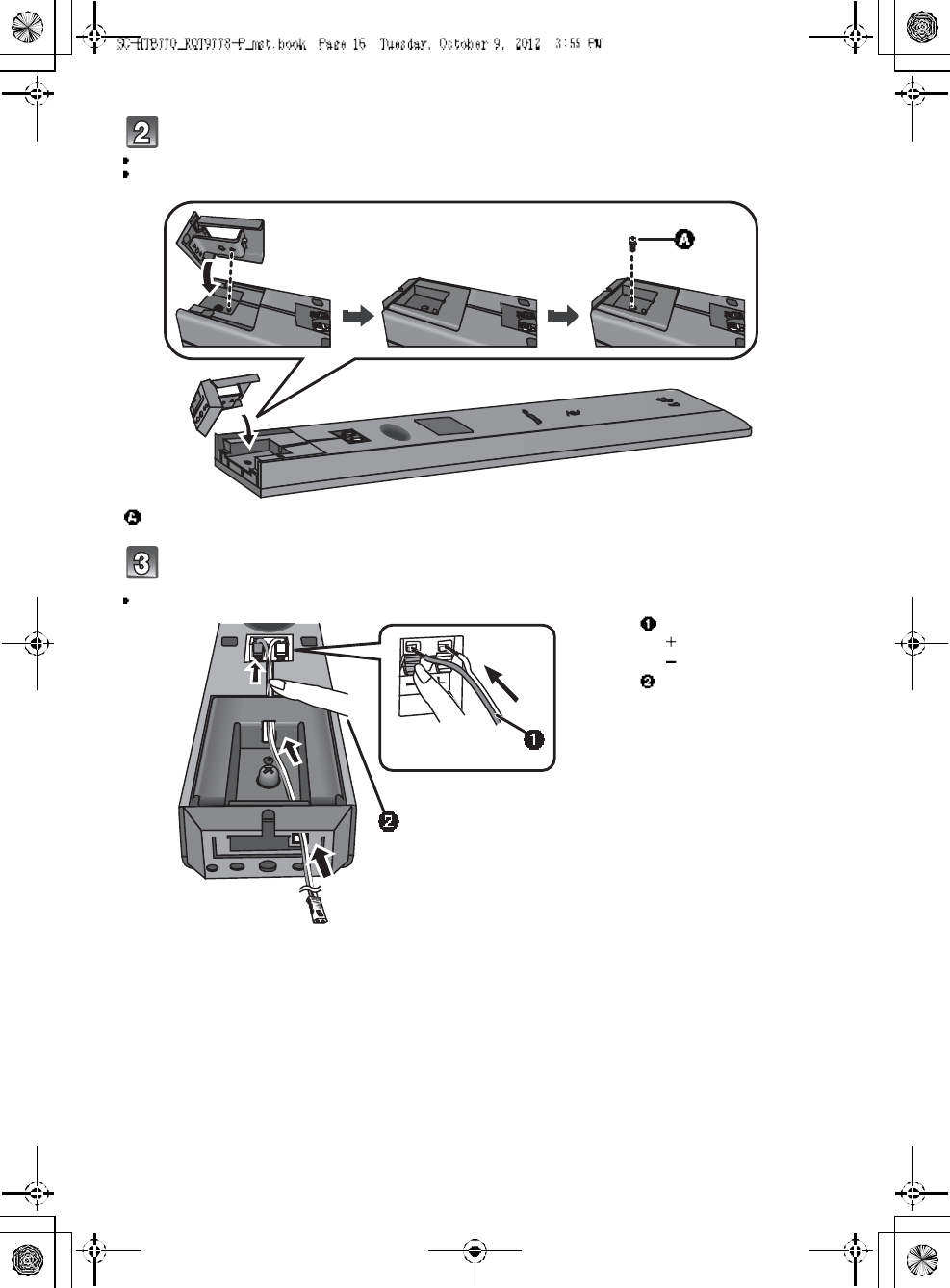
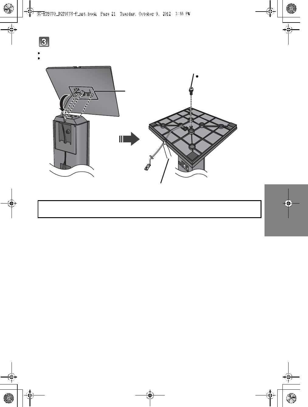
Step 2 Assembling the speakers
For a safety measure to prevent the speakers from falling, refer to page 22.
To prevent damage or scratches, lay down a soft cloth and perform the assembly on it.
Assemble the speakers.
The two front speakers are interchangeable.
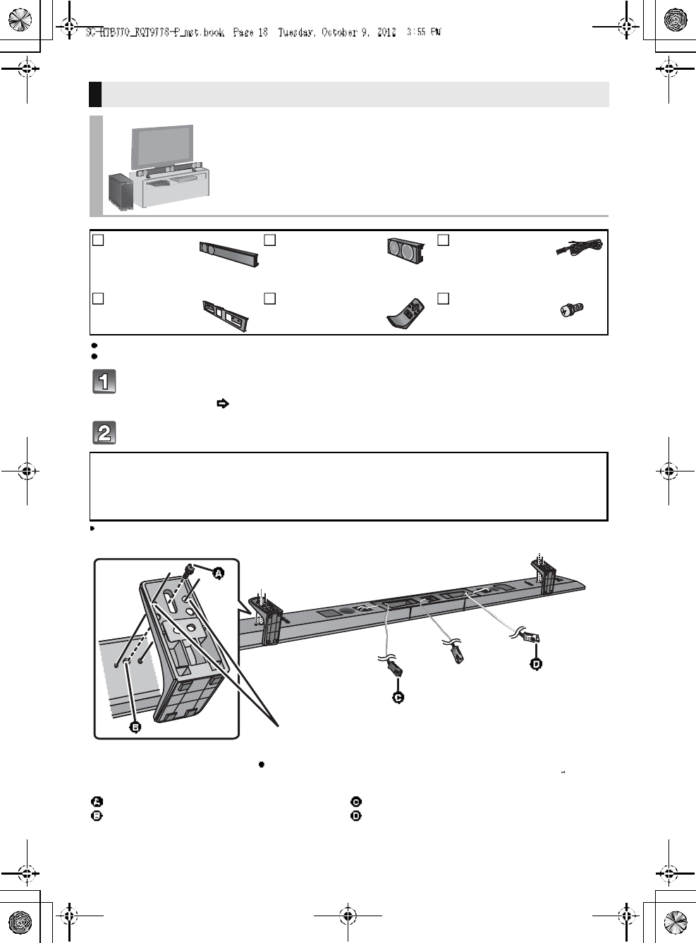
When attaching the speakers to a wall
Place the speakers horizontally
2Front
speakers
1 Center speaker 3 Speaker cables
WHITE: Left
RED: Right
GREEN: Center
1Metal bracket 4 Screws
Screw (supplied)
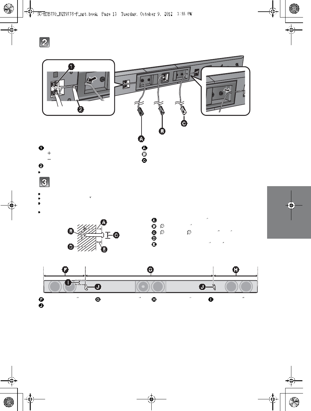
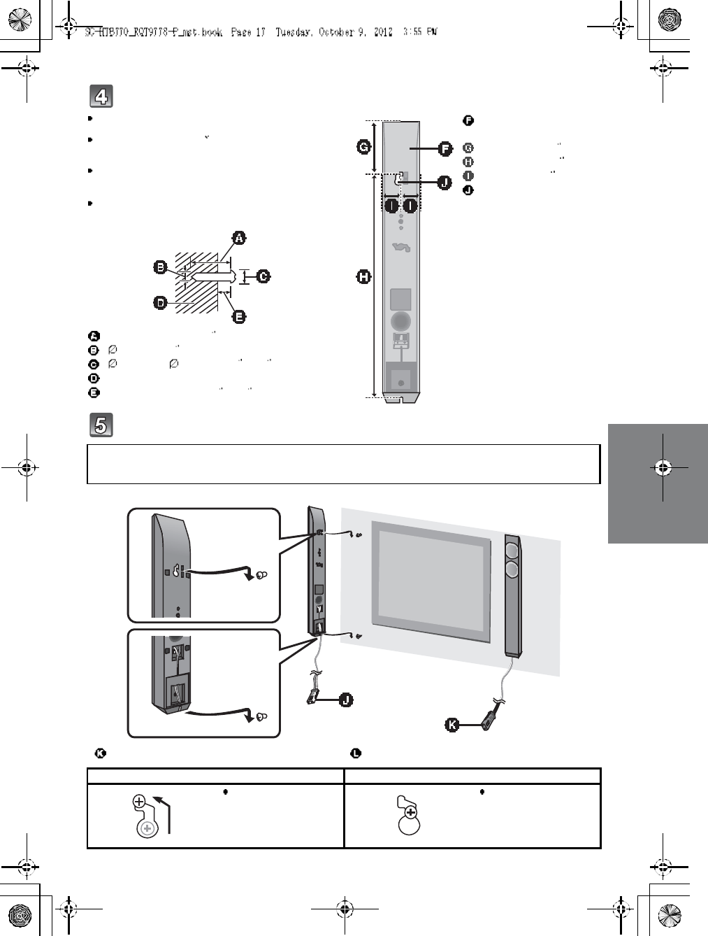
Be sure to insert the screws following the order as indicated in the illustration.
Keep the screws out of reach of children to prevent swallowing.
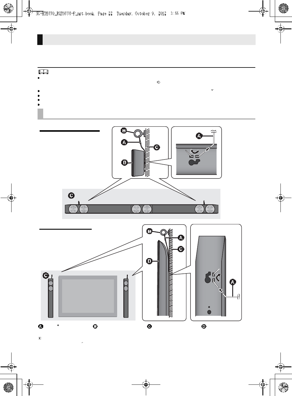
RQT9778 13
Connect the speaker cables.
Insert the wire fully, taking care not to insert beyond the wire insulation.
Drive a screw into the wall.
Use the measurements indicated below to identify the screwing positions on the wall.
Leave at least 20 mm (25/32 ) of space above and on each side of the speaker to allow enough space for fitting the speaker.
The position on the wall where the screw is to be attached, as well as the screw, should be capable of supporting over 33 kg
(72.8 lbs).
Keep the screws out of reach of children to prevent swallowing.
Insert the wire fully.
: White
: Blue line
Press into th e groove.
Right speaker connector
Center speaker connector
Left speaker connector
At least 30 mm (1 3/16 )
4.0 mm (5
/32 )
7.0 mm to 9.4 mm (9
/32 to 3
/8)
Wall or pillar
5.5 mm to 6.5 mm (7/32 to 1/4)
248 mm (9 3/4)745 mm (29 11
/32 )238 mm (9 3/8)20 mm (25
/32 )
Wall mounting hole
Pu sh
Red
White
Green
Front view (semi-transparent image)
14 R QT 97 78
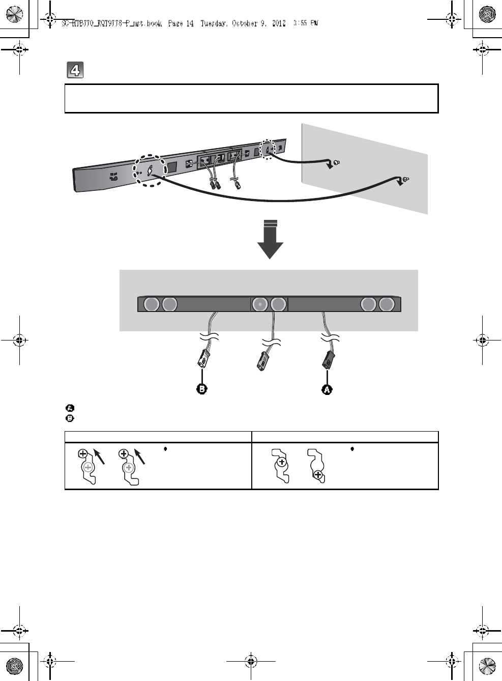
Fit the speaker securely onto the screw(s).
Red connector: The speaker attached to the red connector cable is to be place on the right side
White connector: The speaker attached to the white connector cable is to be place on the left side
Right speaker connector
Left speaker connector
DO DO NOT
Move the speaker so
that the screw is in this
position.
In this position, the
speaker will likely fall if
moved to the left or
right.
Red
White
RQT9778 15
For a safety measure to prevent the speakers from falling, refer to page 22.
To prevent damage or scratches, lay down a soft cloth and perform the assembly on it.
Attach the side caps and speaker feet to the center speaker and connect
the speaker cable.
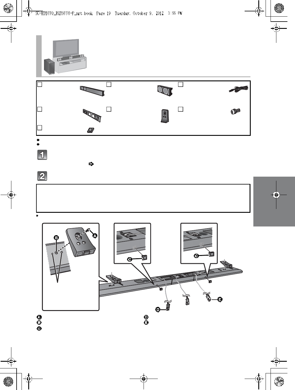
Place the front speakers vertically
2Front
speakers
1 Center speaker 3 Speaker cables
WHITE: Left
RED: Right
GREEN: Center
2Stand nec ks 2 Side caps 4 Screws
2 Speaker feet
Screw (supplied)
Speaker foot (supplied)
Center speaker connector
Insert the wire fully.
: White
: Blue line
Pu sh
Green
16 R QT 97 78
Attach the stand neck.
The two front speakers are interchangeable.
Keep the screws out of reach of children to prevent swallowing.
Connect the speaker cables.
Insert the wire fully, taking care not to insert beyond the wire insulation.
Screw (supplied)
Insert the wire fully.
: White
: Blue line
Press into the groove.
Pu sh
RQT9778 17
Drive a screw into the wall.
Fit the front speaker(s) securely onto the screw(s).
Use the measurements indicated below to identify the
screwing positions on the wall.
Leave at least 20 mm (25/32 ) of space above and on each
side of the front speaker to allow enough space for fitting
the front speaker.
The position in the wall where the screw is to be attached
as well as the screw should be capable of supporting over
33kg (72.8 lb s).
Keep the screws out of reach of children to prevent
swallowing.
At least 30 mm (1 3/16 )
4.0 mm (5
/32 )
7.0 mm to 9.4 mm (9/32 to 3/8)
Wall or pillar
5.5 mm to 6.5 mm (7/32 to 1/4)
Front speaker
(Rear view)
100 mm (3 15/16 )
436 mm (17 5/32 )
34 mm (1 11
/32 )
Wall mounting hole
Red connector: The speaker attached to the red connector cable is to be place on the right side.
White connector: The speaker attached to the whi te connector cable is to be place on the left side.
Left speaker connector Right speaker connector
DO DO NOT
Move the front speaker
so that the screw is in
this po si tio n.
In thi s positi on, the front
speaker will likely fall if
moved to the left or
right.
Red
White
18 R QT 97 78
For a safety measure to prevent the speakers from falling, refer to page 22.
To prevent damage or scratches, lay down a soft cloth and perform the assembly on it.
Assemble the speakers following steps 1 and 2 of Place the speakers
horizontally ( 12).
Attach the leg stands .
Keep the screws out of reach of children to prevent swallowing.
When placing the speakers on a table
Place the speakers using the leg stands
2Front
speakers
1 Center speaker 3 Speaker cables
WHITE: Left
RED: Right
GREEN: Center
1Metal bracket 2Leg stands 6 Screws
Red connector: With the speaker facing down, the speaker attached to the red connector cable is to
be place on the left side.
White connector: With the speaker facing down, the speaker attached to the white connector cable is
to be place on the right side.
Screw (supplied)
Screw hole
Right speaker connector
Left speaker connector
Align the higher or lower holes with the projecting parts on the
speaker.
By changing the position that the stand is attached to the
projecting parts, the height can be adjusted by 10 mm (13
/32 ).
Red
White
RQT9778 19
For a safety measure to prevent the speakers from falling, refer to page 22.
To prevent damage or scratches, lay down a soft cloth and perform the assembly on it.
Assemble the speakers following steps 1 and 2 of Place the speakers
horizontally ( 12).
Attach the support legs and speaker feet.
Keep the screws and the speaker feet out of reach of children to prevent swallowing.
Place the speakers using the support legs and
speaker feet
2Front
speakers
1 Center speaker 3 Speaker cables
WHITE: Left
RED: Right
GREEN: Center
1Metal bracket 2 Support legs 6 Screws
2 Speaker feet
Red connector: With the speaker facing down, the speaker attached to the red connector cable is to
be place on the left side.
White connector: With the speaker facing down, the speaker attached to the whi te connector cable is
to be place on the right side.
Screw (supplied)
Screw hole
Speaker foot (supplied)
Right speaker connector
Left speaker connector
Align the projecting
parts on the speaker
with support leg.
Red
White
20 R QT 97 78
For a safety measure to prevent the speakers from falling, refer to page 22.
To prevent damage or scratches, lay down a soft cloth and perform the assembly on it.
Assemble the speakers following step 1 and 2 of Place the speakers
vertically ( 15).
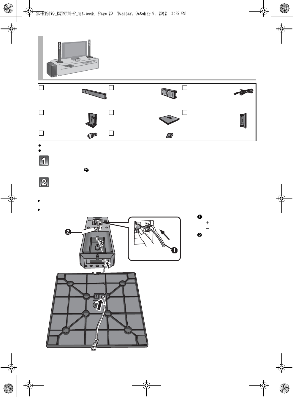
Insert the speaker cable through the speaker base and connect the
speaker cables.
Be sure to insert the speaker cable through the threading hole as indicated in the illustration. (If the speaker cable is twist ed, it
might not fit through the opening. Straighten the speaker cable before inserting.)
Insert the wire fully, taking care not to insert beyond the wire insulation.
Place the front speakers using the speaker
bases
2Front
speakers
1 Center speaker 3 Speaker cables
WHITE: Left
RED: Right
GREEN: Center
2Stand nec ks 2Speaker bases 2 Side caps
6 Screws 2 Speaker feet
Insert the wire fully.
: White
: Blue line
Press into the groove.
Pu sh
RQT9778 21
Attach the speaker base to the front speaker.
The two front speakers are interchangeable.
Keep the screws out of reach of children to prevent swallowing.
Red connector: The speaker attached to the red connector cable is to be place on the right side.
White connector: The speaker attached to the whi te connector cable is to be place on the left side.
Align the projecting
parts with the holes
on the speaker.
Press into th e groove.
Screw (supplied)
Tighten securely.
22 R QT 97 78
To prevent the speakers from falling, it is recommended, as an additional
protection measure, to attach the speakers to the wall or table with a fall
prevention cord (hereafter cord).
Consultation with a qualified installation specialist concerning the appropriate procedure when attaching to a concrete wall or a
surface that may not have strong enough support is recommended ( 13, 17). Improper attachment may resu lt in damage to
the wall and speakers, and personal injury.
Use a cord that is capable of supporting over 10 k g (22.05 lbs) (with a diameter of about 1.5 mm (1/16 )).
The safety holder is to minimize the possibility of damage and harm, but it does not guarantee this effect.
Keep the screws out of reach of children to prevent swallowing.
Make sure that the slack of the cord is minimal.
Additional speaker fall prevention measures
When attaching the speakers to a wall
Cord Screw eye Wall Wall-mounted
speakers
If the cord cannot be threaded through the holes, try bending the cord in 2 locations,
about 10 mm (13/32 ) apart from the tip, at an angle of 45o (as illustrated above).
Horizontal placement
Vertical placement
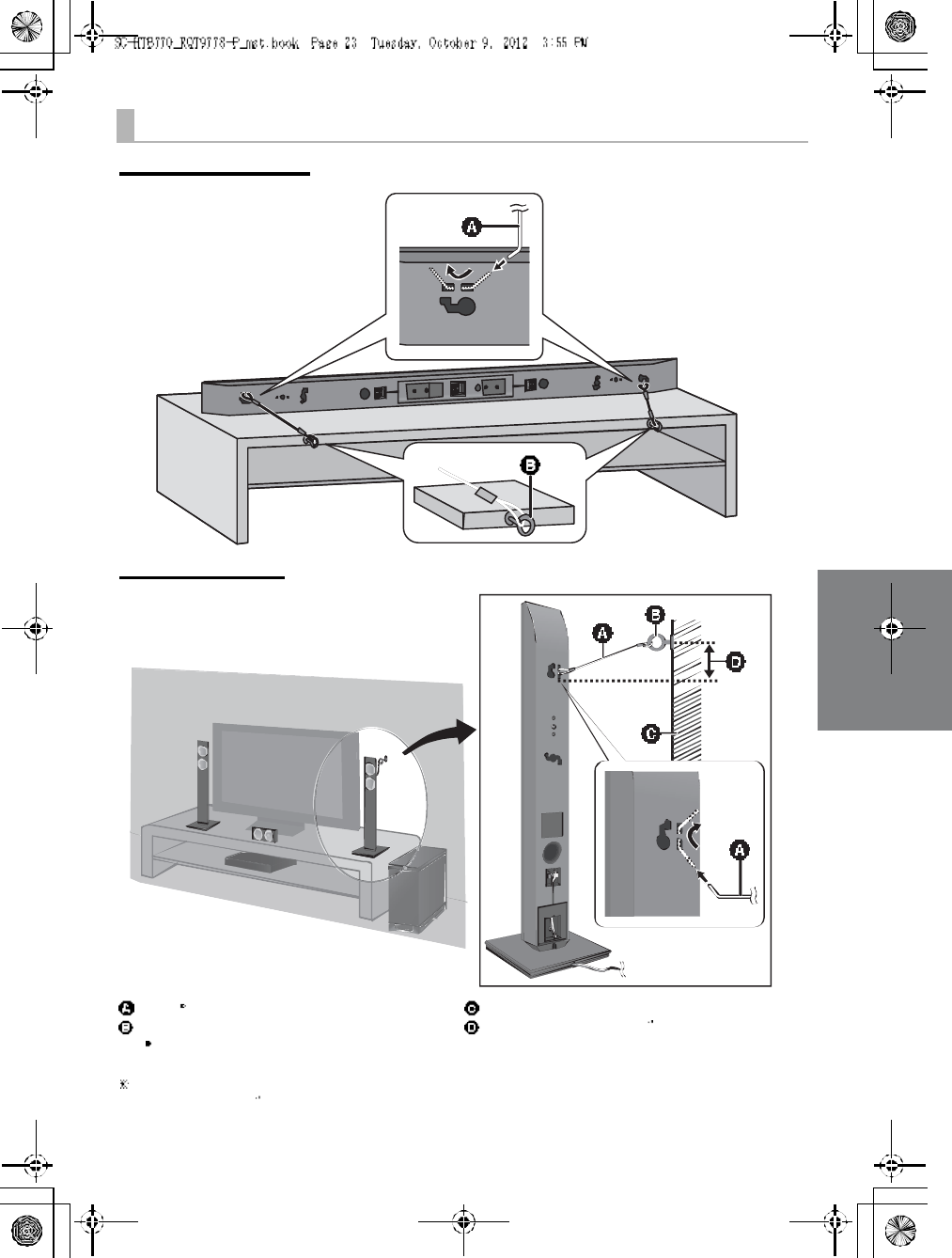
RQT9778 23
When placing the speakers on a table
Horizontal placement
Vertical placement
Cord
Screw eye
Dependin g on the placement of the speakers, the
screwing position of the screw eye may differ.
Wall
Approx. 150 mm (5 29
/32 )
If the cord cannot be threaded through the holes, try bending the cord in 2 locations,
about 10 mm (13/32 ) apart from the tip, at an angle of 45o (as illustrated above).
24 R QT 97 78
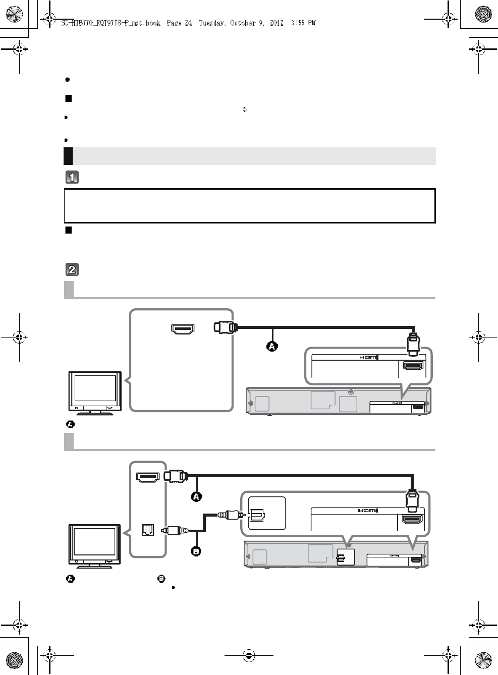
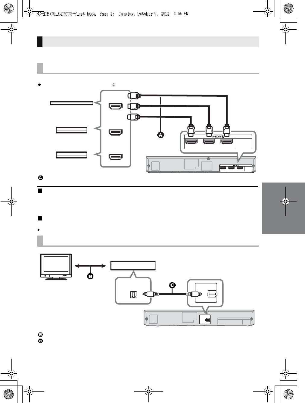
Step 3 Connections
Turn off all equipment before connection and read the appropriate owners manual.
Do not connect the AC power supply cord until all other connections are complete.
HDMI
The HDMI connection supports VIERA Link HDAVI Control ( 30) when used with a compatible Panasonic TV.
Use the High Speed HDMI Cables. It is recommended that you use Panasonics HDMI cable.
Recommended part number (High Speed HDMI cable):
RP-CDHS15 (1.5 m/4.9 ft), RP-CDHS30 (3.0 m/9.8 ft), RP-CDHS50 (5.0 m/16.4 ft), etc.
Non-HDMI-compliant cables cannot be utilized.
Verify if the TVs HDMI terminal is labeled HDMI (ARC).
What is ARC?
ARC is an abbreviation of Audio Return Channel, also known as HDMI ARC. It refers to one of the HDMI functions. When you
connect the ma in unit to the terminal labeled HDMI (ARC)on the TV, the optical digital audio cable that is u sually required in
order to listen to sound from a TV is no longer required, and TV pictures and sound can be enjoyed with a single HDMI cable.
Make the connection.
Connection with the TV
Connection differs depending on the label printed next to the HDMI terminal.
Labeled HDMI (ARC): Connection [A]
Not Labeled HDMI (ARC): Connection [B]
[A] Labeled HDMI (ARC)
HDMI cable
[B] Not labeled HDMI (ARC)
HDMI cable Optical digital audio cable
When you use the optical digital audio cable, insert the tip correctly into the terminal.
AC IN
TV (ARC)
AV OUT
DIGITAL
AU DIO
IN
S PE AK E RS /H AUT- P ARLE U RS
HDMI IN (ARC)
TV (ARC)
AV OUT
Be sure to connect to
the TVs ARC
compatible terminal.
(Refer to th e operating
instructions for the TV.)
TV
AC IN
TV (ARC)
AV OUT
DIGITAL
AU DIO
IN
TV
( OPT1)
S PE AK E RS /H AUT- P ARLE U RS
HDMI IN
OPTICAL
OUT
TV (ARC)
AV OUT
D I GI T AL
AUDIO
IN
TV
(OPT1)
TV
RQT9778 25
You can direct the audio signal from the connected Blu-ray DiscTM player, DVD player, Set Top Box, etc.
to this unit.
Preparation
Connect the main unit to the TV ( 24).
HDMI standby pass-through
Even if the main unit is in standby mode, the audio and/or vide o signal from the device connected to the BD/DVD, AUX1 or AUX2
terminal will be sent to the TV connected to the HDMI OUT terminal (the sound will not be output from this unit). Wh en devices
are connected to all BD/DVD, AUX1 and AUX2 terminals, audio and/or video signal of the device whose input is lastly selected is
output.
3D compatibility
Compatible with FULL HD 3D TV and Blu-ray DiscTM player.
The main unit can through pass the 3D video signal from a 3D compatible Blu-ray DiscTM player to a FULL HD 3D TV.
Connection with other devices
When the device has an HDMI terminal
HDMI cable
When the device has an optical digital audio output terminal
Refer to the operating instructions of the respective devices for the optimal connection
Optical digital audio cable
AC IN A V IN BD/DVDBD/DVDAU X1 ( HDMI 1)( HDMI 2)
AU X2
( HDMI 3)
DIGITAL
AU DIO
IN
S PE AK E RS /H AUT- P ARLE U RS
AV IN
BD/DVDBD/DVDA U X1
(HDMI1)(HDMI2)
A U X2
(HDMI3)
HDMI OUT
HDMI OUT
HDMI OUT
e.g., Set top box
e.g., Blu-ray DiscTM player
e.g., Video game console
AC IN
DIGITAL
AU DIO
IN
AU X3
( OPT2)
S PE AK E RS /H AUT- P ARLE U RS
D I GI T AL
AUDIO
IN
A U X3
(OPT2)
OPTICAL OUT
e.g., Set top box
TV
26 R QT 97 78
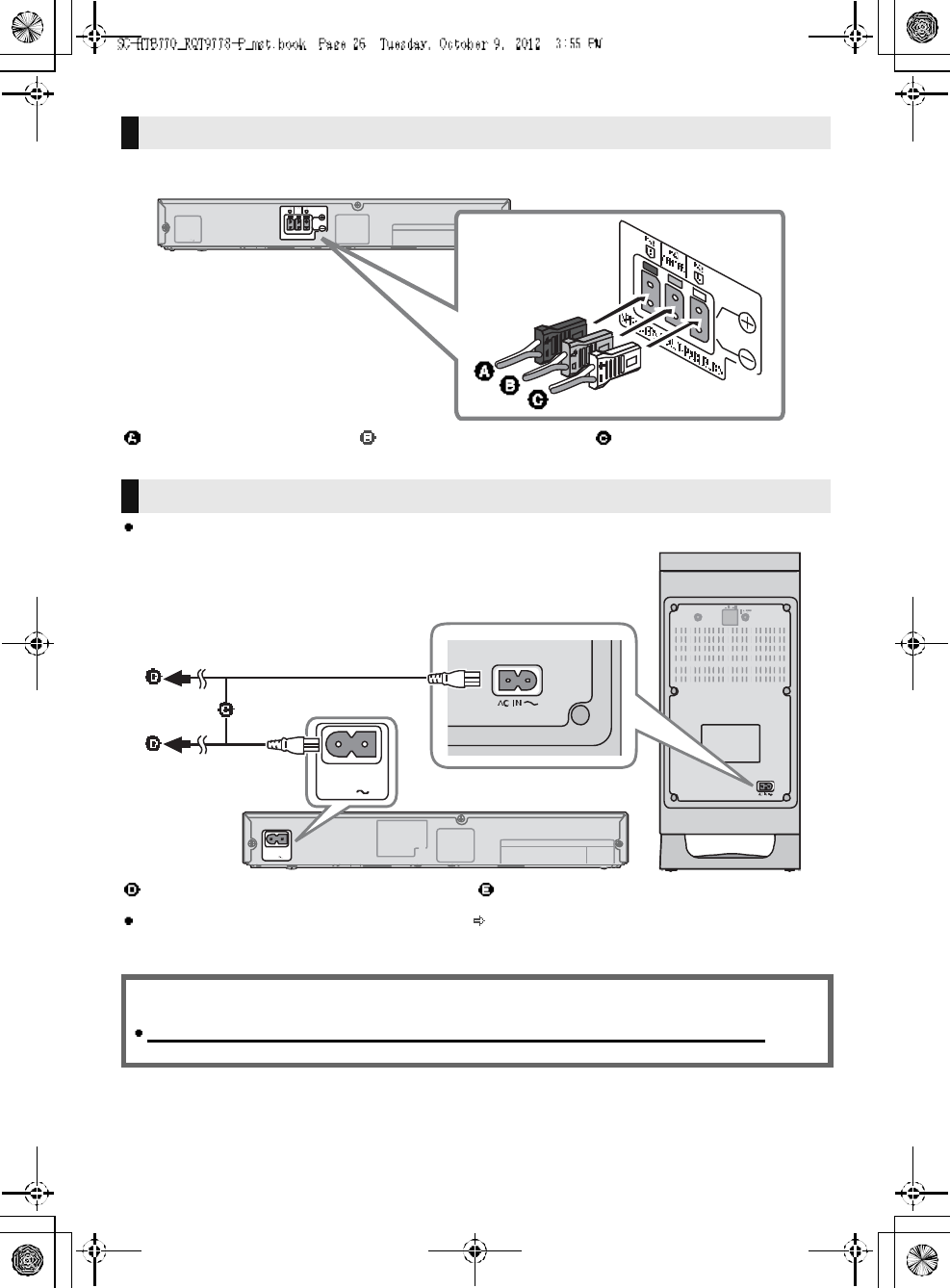
Match the connector shape and connect to the terminals of the same color.
Connect only after all other connections are complete.
This unit consumes a small amount of AC power ( 35) even when it is turned off. In the interest of
power conservation, if you will not be using this unit for a long time, unplug it from the household AC
outlet.
Speaker cable connection
RED
Right speaker connector
GREEN
Center speaker connector
WH ITE
Left speaker connector
AC power supply cord connection
AC power supply cord To a household AC outlet
Saving energy
The main unit is designed to conserve its power consumption and save energy.
The main unit will automatically switch to standby mode when
no signal is input and no operation is performed for approx. 30 minutes.
RQT9778 27
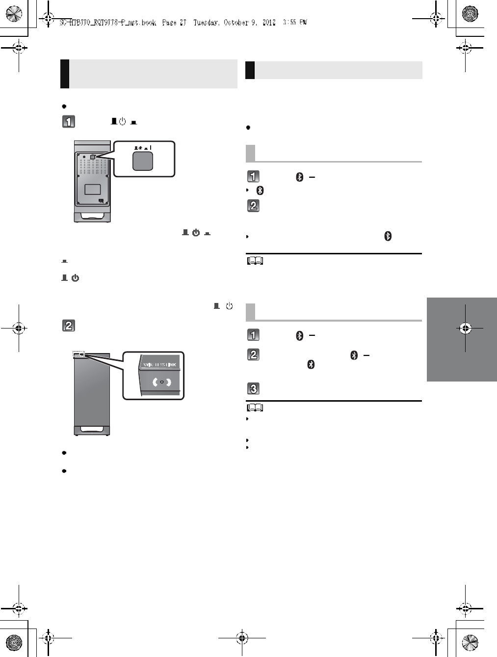
Preparation
Turn on the main unit.
Press [ I].
Active subwoofer on/off button [ , I]
Use this button to turn the active subwoo fer on and
off.
I:
The active subwoofer is on
:
The active subwoofer is off
The active subwoofer will still consume a small
amount of power even when it is turned off ( , )
Check that the wireless link is
activated.
WIRELESS LINK indicator lights
Red:
The wireless link is not activated.
Green:
The wireless link is activated.
By using the Bluetooth® connection, you can listen
to the sound from the Bluetooth® audio device
from th is unit wirele ssly
Preparation
Turn on the Bluetooth® feature of the device and
place the device near this unit.
Press [, PAIRING].
indicator will blink quickly.
Select SC-HTB770 from the
Bluetooth® devices Bluetooth®
menu.
Once the Bluetooth® device is connected, the indicator
stops flashing and lights up.
Refer to the operating instructions of the Bluetooth ®
device for
further instruction on how to connect a Bluetooth ® device.
If prompted for the passkey on the Bluetooth® device, enter
0000.
Press [, PAIRING].
Press and hold the [ , PAIRING]
until the indicator flashes
quickly.
Repeat step 2 of Pairing a device.
You can register up to 8devices with this unit. If a 9th device
is paired, the device that has not been used for the longest
time will be replaced.
This unit can only be connected to one device at a time.
To chang e the sound quality, refer to Blu etooth®
communication mode on page 31.
Active subwoofer wireless
connection Bluetooth® connection
Pairing a device
Pairing additional devices
28 R QT 97 78
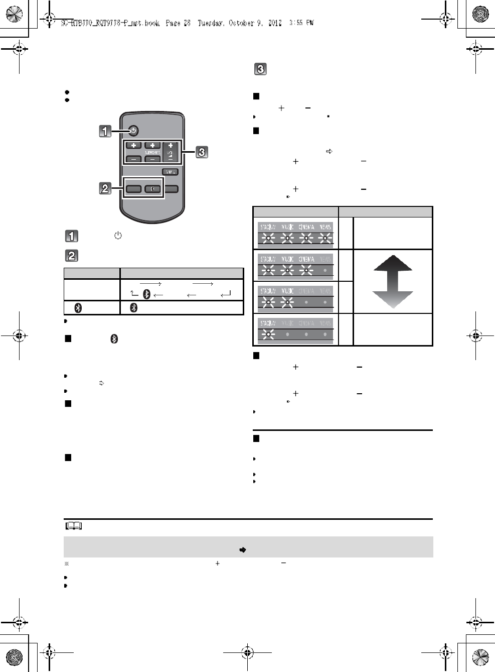
Using this unit
Preparation
Turn on the active subwoofer.
Turn on the TV and/or connected device.
Press [ ] to turn on the main unit.
Select the source.
This remote control cannot be used to control the operations
of the connected devices.
When is selected as the source
On the Bluetooth® device:
Select this uni t as the output sour ce of the Bluetooth®
device and start the p layback.
Make sure that the Bluetooth® device is already paired with
this unit. ( 27)
Playback may pause when a different source is selected.
When BD/DVD , AUX1 or AUX2
is selected as the source
On the connected device:
Select the TVs input for this un it and start the playba ck on
the conne cted device.
When AUX3 is selected as the
source
On the connected device:
Select the TVs input for the device connected to AUX3
termin al and start the pla yback on the conne cted device .
Adjust the volume and sound effect
level.
To adjust the volume of this unit
Press [ VOL ].
Volume range: 1 to 100
To adjust the dialog effect level
This setting will change the level of the Clear-
mode dialog effect. ( 29)
1 Press [ DIALOG LEVEL ] to display the
current level.
2 While the level is displayed:
Press [ DIALOG LEVEL ] to adjust the
level.
To adjust the subwoofer level
1 Press [ SUBWOOFER ] to display the
current level.
2 While the level is displayed:
Press [ SUBWOOFER ] to adjust the
level.
The level indication pattern is the same as dialog effect
level.
To mute the sound
Press [MUTE].
While muting, the sound mode indicators blink
simultaneously.
To cancel, press the button again or adjust the volume.
Muting is canceled if the main unit is turned off.
The sound mo de indicators blin k from left to right ( ) or from right to left ( ) while adjusting.
The indicators will not blink when it has reached the maximum or minimum.
If there is sound coming out of the TVs speakers, reduce the volume of the TV to its minimum.
If the main unit is turned off with the volume setting in the greater half (above 50), the main unit will automatically lower the
volume to the middle (50) when the main unit is turned on (Volume limitation).
To turn this function off, refer to page 33.
Press To select
[INPUT
SELECTOR]
TVBD/DVDAUX1
AUX3 AUX2
[] (Bluetooth®
)
Indication Effect level
4Highest
3
2
1Lowest
If the main unit does not operate as expected or sound is unusual, return the settings to the
factory preset and operate the system again. ( 33)
RQT9778 29
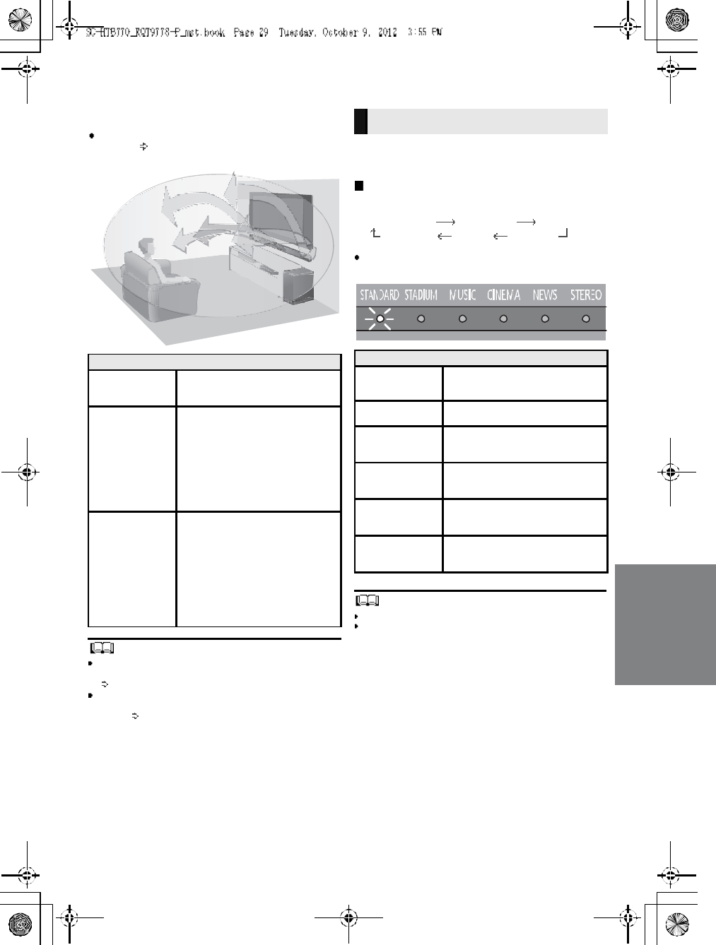
3D sound
This unit provi des a feel ing that the sound and the i mage
ar e as one.
To cha nge the applied effect, refer to Aud io output
modes. ( right)
To turn off Dolby Virtual Speaker and the 3D surround
effects, select STEREO as the audio output mode.
(right)
To turn off the 3D surround and the Clear-mode dialog
effects, refer to Only using the Dolby Virtual Speaker
effect. ( 32)
By changing the aud io ou tput mode , it is possible to enjoy
the sound that is sui table to the TV prog ram or image fro m
the conne cted device.
To select the sound mode
Press [SOUND].
STANDARDSTADIUMMUSIC
STEREO NEWS CINEM A
The i ndi cator for the selected sound mode lig hts.
E.g ., STANDAR D
The setting is maintained until it is changed again.
When usin g the optical digital aud io cable, Dolby Virtual
Speaker and the 3D surround effect will be temporarily
canceled if the audio signals sampling frequency is greater
than 48 kHz.
3D sound
Dolby Virtual
Speaker
With this effect you can enjoy a
surrou nd sound e ffect simi lar to
5.1ch.
3D surround
effect
Adding to the Dol by Virtual
Speaker e ffect, Panasonic has
applie d its own sound field
contr olli ng techn ology to expand
the sou nd field forwards,
backwards, upwards, and
downwa rds, provi ding a sound
with depth and force that better
matche s 3D image s.
Clear-mode
dialog
Sports comm entary and di alogs
from TV dramas are he ar d as if the
sound is comin g from the TV,
gi vi ng the feeling that the sound
and the image are one.
Also, the dialog will stand out from
the other sou nds during nor mal
volu me playback and when the
volu me is lowered for night time
viewi ng.
e.g., Image of 3D sound field
Audio output modes
Sound mode
STANDARD
(Factory preset)
Produces a sound best suited for
dr amas an d comedy shows.
STADIUMProduces a hig hly realistic soun d
for live broadcasts of sports.
MUSIC
Re-creates the sound of musical
instruments and songs with an
expansive sound.
CINEMA
Produces a powerful , three-
dimentional sound unique to
movies.
NEWS
Enha nces the voices o f news and
sports commentaries for clear er
he ari ng.
STERE O
You can play a ny source in stereo.
Dol by Virtua l Speaker and 3D
surr oun d effects are turne d off.
30 R QT 97 78
Linked operations with the TV
(VIERA LinkTMHDAVI ControlTM )
Preparation
Con firm that the HDMI connection has been made.
(24, 2 5)
Set the HDAVI Control oper ation s on the connecte d
equipment (e.g., TV).
For the optimal HDAVI Co ntrol operations chan ge
the foll owing settings on the connected TV 1.
Set the default speaker settings to this unit.2
Set the speaker selection settings to this unit.
Turn o n all HDAVI Control com patibl e equipment
and select the TVs in put for this unit so that the
HDAVI Control function works prope rly.
If a device is co nne cte d t o th e HDMI IN te rminal, st art
pla y to che ck tha t the picture is di splaye d on the TV
correctly.
When the connection or settings are changed,
repeat this procedure.
1 The availability and function of the settings may vary
depending on the TV. Refer to the operating instructions
for the TV for details.
2 If the TV has a default speaker setting within the VIERA
Link setting items, choosing this unit as the default
speaker will automatically change the speaker selection to
this unit.
VIERA Link HDAVI Control, based on the control functions
provided by HDMI which is an industry standard known as
HDMI CEC (Consumer Electronics Control), is a unique
function that we have developed and added. As such, its
operation with other manufacturers equipment that
supports HDMI CEC cannot be guarante ed.
This unit supports HDAVI Control 5 function.
HDAVI Control 5 is the newest standard (current as of
November, 2 011) for Panasonics HDAVI Control compatible
equipment. This standard is compatible with Panasonics
conventional HDAVI equipment.
Please refer to individual manuals for other manufacturers
equipment supporting VIERA Link function.
To make sure that the audio is outpu t from this unit, turn
the main unit o n by using the TVs remo te control a nd
sele cting home theater from the sp eaker menu of VIERA
Li nk menu. The avail abil ity an d function of th e settings
may var y depe nd ing on the TV. Refer to t he op er ating
instructions for the TV for details.
Speaker control
You can se lect whethe r audio output is from this unit or
the TV speake rs by u sing the TV menu se ttings.
Home theater
This unit is active.
When this unit is in standby mode, changing the TV
speakers to this unit in the VIERA Link menu will
auto matically turn this unit on and select TV as the source.
You can control the volume setting of this unit using the
volume or mute button on the TV remote control.
If you turn off this unit, TV speakers will be automatically
activated.
Audio will automa tically be output from this unit if the TV is
compatible to VIERA Link HDAVI Control 4 or later.
TV
TV spe aker s are active.
The volume of this unit is set to its minimum.
Autom atic input switching
When th e fo llowin g operatio ns a re per formed, this unit will
automatica lly change the inpu t to the corr espondi ng
source.
When play starts on an HDMI connected device. 3
When the TV input or the TV channel is changed.
3 If the speaker output setting on the TV is set to this unit,
th e TV and this unit turn on automatically (Power on link).
Power off link
When the TV is turned off, the main unit also turns off
automatica lly. ( This function does not wo rk when
Bl ue to oth® is the source.)
Automatic lip-sync function
(for HDAVI Control 3 or later)
Del ay between au dio and video is automaticall y adjusted
by adding t ime-l ag to the au dio output, enabl ing you to
enjoy smooth audio for the pi cture.
Th e delay information is automatically set if the TV is
co mpatible to VIERA Link HDAVI Control 3 or later and the
VIERA Link is set to on.
What is VIERA Link HDAVI
Control?
VIERA LinkTM is a new name for EZ SyncTM.
VIERA Link HDAVI Control is a convenient
function that offers linked operations of this
unit, and a Panasonic TV (VIERA) under
HDAVI Control.
You can use this function by connecting the
equipment with an HDMI cable. See the
operating instructions for connected
equipment for operational details.
What you can do with
VIERA Link HDAVI
Control
RQT9778 31
Advanced operations
To di splay the cur rent audio format,
Press and hold [SOUND] for more than
4 sec.
The current audio format is indicated for 5 s ec.
The a udi o format status is also ind icated for 5 sec if the
audio fo rmat on the se lected source (TV, Blu-r ay Disc/
DVD Player, etc.) is changed.
Cha ng e the du al au dio from m ain to seconda ry.
This setting wi ll only work if the audio outpu t setting on
the connected TV or player, etc. is set to "Bitstream"
and dual audio is available in the aud io sou rce.
Press and hold [MUTE] for more than
4 sec.
While the setting is displayed, press
[MUTE] to change the setting.
The indicator for the selected setting blinks for 20 sec and
then exits the setting mode.
The setting is maintained until it is changed aga in.
The same setting is used for all digital audio sources.
With this functio n, you can pr even t sudde n loud sounds.
The outpu t will be reduced automati cally when the input
exceeds a certain level.
Press and hold [INPUT SELE CTOR]
on remote controller for more than
4sec.
While the setting is displayed, press
[INPUT SELECTOR] to change the
setting.
The indicator for the selected setting blinks for 20 sec and
then exits the setting mode.
The setting changes each time [INPUT SELECTOR] is
pressed.
The setting is maintained until it is changed again.
Default setting of this function is OFF.
You can select d ifferent mod es to suit the type of
connections which emp hasis on connectivity or high
quality audio.
Make su re that a Bluetooth® device i s alrea dy pair ed
with this unit. ( 27)
Disable the Bluetooth® connection of
the device.
indicator will blink slowly.
Press [LINK MODE, ] to display the
current mode.
While the mode is displayed, press
[LINK MODE, ] to select the mode.
The setting changes each time [LINK MODE, ] is
pressed.
The indicator for the selected setting blinks for 10 sec and
then exits the setting mode.
The setting is maintained until it is changed again.
Audio format indicator
STADIUM indicator blinks:
Dolby Digital is the audio format.
MUSIC indicator blinks:
DTS is the audio format.
CINEMA indicator blinks:
PCM or LPCM is the audio format.
Changing the dual audio
STAND ARD indicator blinks ( ):
Main (Factory preset)
STEREO indicator blinks ( ):
Secondary
(SAP: Secondary Audio Program)
, : Main and secondary
Auto gain control
STANDARD indicator blinks:
Auto gain control is on.
STEREO indicator blinks:
Auto gain control is off.
(Factory preset)
Bluetooth® communication
mode
STANDARD indicator blinks:
MODE1 (Factory preset)
Emphasis on connectivity
STEREO indicator blinks:
MODE2
Emphasis on audio quality
32 R QT 97 78
Dep en ding on your p referen ce, It is possi ble to tur n off the
3D sur round effect and the clear-mod e dia log effect.
While pressing and holding [SOUND]
on the remote control, press and
hold [VOL ] on t he main unit for
more than 4 sec.
While the setting is displayed, press
[SOUND] to change the setting.
The setting changes each time [ SOUND] is presse d.
The indicator for the selected setting blinks for 20 sec and
then exits the setting mode.
This setting will be reset to on when this unit is turned off.
When off is selected, the dialog effect level cannot be
adjusted.
You can tur n of f di mmer mode a nd keep the LED
ind icators bright.
While pressing and holding [INPUT
SELECTOR] on the remote control, press
and hold [ VOL] on the main unit to turn
off Dimmer mode.
The indicator for the current condition will turn brighter.
The setting is maintained until it is changed again.
Default setting of this function is on.
To turn on d immer mode, repeat the operation above.
After performancing the operation, the indicator for the
current condition will be dim.
Remote control code
When other Panasonic de vices r espond to this units
re mote contro l, ch ang e the remote control code on the
mai n unit and the remote contr ol.
Preparation
Turn off all other Panasonic products.
Turn on the mai n unit.
Change the remote control code to code 2:
1 Aim the remote control at this units remote
control sensor.
2 Press and hold [MUTE] and [ ] on the remote
control for more than 4 sec.
Al l the indicators will bl ink for 10 sec when t he code of
this unit is changed.
The se tting is maintai ned until it i s changed again.
If this unit does not operate after changing the code, re peat
steps 1 and 2.
To change the remote control code to code 1, repeat the
steps above, but replace []with [INPUT SELECTOR].
To reduce the clear-mode dialog effect
When the di alog d oe s not sound natural while the vol ume
is set low, it is possible to reduce the dialog enhancing
effect a s foll ows:
While pressing and holding [SOUND] on the
remote control, press and hold [ VOL] on the
main unit for more than 2 sec.
All the indicators will blink once when the clear-mode dialog
effect is reduced.
Even if clear-mode dialog effect is reduced, dialog effect
level is still adjustable.
To reset the setting, return to the factory preset. ( 33)
Only using the Dolby
Virtual Speaker effect
STANDARD indicator blinks:
3D surround effect and clear-mode
dialog effect is on.
STEREO indicator blinks:
3D surround effect and clear-mode
dialog effect is off.
Dimmer mode
Others
RQT9778 33
To turn off VIERA Link HDAVI
Control
When HDAVI Control com patibl e equipment doe s not
work well with this unit, for example, it is possible to turn
off this function as follows:
When VIERA Link is turned off the ARC function is not
availab le. Be sur e to conn ect the optica l digital a ud io
cable. ( 24)
1 While pressing and holding [MUTE] on the
remote control, press and hold [ VOL] on the
main unit for more than 4 sec.
2 After the setting has changed, turn off all the
connected devices and then turn them on
again.
All the in dicators will blink once when VIERA Link HDAVI
Control is turned off.
To reset the setting, return to the factory preset. ( right)
To turn off the volume limitation
If a state of the lowered volume disturbs you every time
this uni t turns on, for example, it is possible to turn off this
function as follows:
While pressing and holding [MUTE] on the remote
control, press and hold [VOL ] on the main unit
for more than 2 sec.
All the in dicators will blink once when the volume limitation
is turned off.
To reset the setting, return to the factory preset. ( right)
Troubleshooting
Before requ esting service, ma ke the following checks. If
you a re in doubt about some of the check poi nts, or if the
solu ti ons indicated in the following guide do not solve the
pr obl em, r efer to Custom er Services Directory ( United
States and Puerto Rico) o n page 38 i f you reside in the
U.S. A. or Puer to Rico, o r re fe r t o WARRANTY SERVI CE
on p age 39 if you reside in Cana da.
No power.
Inser t the A C power supply cord securely. ( 26)
After turn ing the main unit on, if the indicators blink and
the main unit immediately turns off, unplug the AC
power supply cord a nd consult your dealer.
The remote control does not work properly.
The b attery is dep leted. Rep lace i t with a new one.
(9)
It is possible tha t the insulation she et h as no t be en
re moved . Remove the insulation shee t. ( 9)
It may be necessary to set the code of the remote
contr ol ag ain a fter chang ing the battery of the remote
con tr ol. ( 32)
Use the remote control within the co rrect opera ti on
range. ( 9)
The TV indicator blinks.
Rem ove the AC power suppl y cor d and consul t your
dealer. If ther e are any other indi cators blinking , be sure
to infor m your dealer about the blinking i ndi ca tors.
The main uni t is automatically switched to
standby mode.
The main unit w ill automatically switch to standby mod e
whe n no signa l i s input and no o per ation i s perform ed for
approx. 30 minutes. ( 26)
The main unit is turned off when the TVs
speakers are selected in the speaker control.
This is a normal feature when using VIERA Link (H DAVI
Con tr ol 4 or l ater). Please read the operatin g instructions
for the TV for details about its power save feature. ( 30)
To return to the factory preset.
While the main unit is on, press [ /I] on the main
unit for more than 4 sec.
(All the indicators will blink twice when the main
unit is reset.)
If thi s unit does not operate as expected,
returning the settings to the factory preset
may solve the problem.
The remote control code will return to when
the main unit is returned to the factory preset.
To change the remote control code, refer to
page 32.
General operation
34 R QT 97 78
This unit does not operate correctly.
If the HDMI cabl e is connected to the wrong terminal
(HDMI IN or HDMI OUT), this unit will not operate
corr ectly. Turn the main unit off, disconnect the AC po wer
supply cord and reconnect the HDMI cable(s). ( 24 , 2 5)
VIERA Link related operations no longer
function properly.
Che ck the VIERA Link setti ng on the connected
devices.
Have you tu rned the VIERA Link settings off? ( 33)
When the HDMI connections are changed, after a
power failure o r after the AC power supply cord h as
been removed, VIERA Link opera ti ons may not function
pr ope rly.
Turn o n all the devices tha t ar e connected to the TV
with an HDMI cable and then tur n the TV on .
Turn off the VIERA Link settings of the TV and turn it
on again. For details refer to the op erating
instructions for the TV.
While this unit and the TV ar e connected with the
HDMI cable, turn on the TV and then remove the
mai n uni ts AC power supply cord and reconnect it
again.
The first few seconds of audio cannot be heard
when using the HDMI connection.
This may occur dur ing DVD-Vid eo chapter playba ck.
Cha ng e the dig ital audio output setting on the connected
device from Bitstream to PCM.
When operating an HDMI compatible device of
a different brand, the main unit reacts in an
unwanted manner.
HDAVI Control commands may use a differ ent signal
depe nding on th e brand of the device. In thi s case, turn
VIERA Link off. ( 33)
Pairing cannot be done.
Che ck the Bluetooth® devi ce conditi on.
The device cannot be connected.
The pairi ng of the device was unsucce ssful. Try pairing
the device again.
The pairi ng of the device has been repl aced. P air the
device again. ( 27)
This unit might be connected to a differe nt device.
Disconnect the other device an d try pairi ng the device
again.
The device is connected but audio cannot be
heard through this unit.
For so me bui lt-in Bl uetooth® devices, you have to set the
audio o utput to SC- HTB7 70 manually. Read the
operati ng instructions for the device for details.
Sound from the device is uneven.
The device is out of the 10 m (33 ft) com muni cation
ra nge . Bring th e device closer to the main unit.
Remove any o bstacle between the m ain unit a nd the
device.
Swi tch off any wireless LAN device.
Select MODE1 for stab le communication. ( 31)
No sound (or image).
Turn muting off. ( 28)
Che ck the connections to the other devices. ( 24, 25)
Make su re that the received aud io signal is compati ble
with this unit. ( 35)
Turn this unit off and then on ag ain.
If this unit is connected to the TV with only an HDMI
cable, make sure that the TVs HDMI ter minal is labeled
HDMI (ARC). If not, connect using the optical digital
audio cable. ( 24)
If this unit is connected to a Panasonic TV and turned
on u sing the button on the mai n uni t or the remote
contr ol, sound might not be outpu t from this uni t. In this
case, turn the main unit on using the TVs remote
con trol. ( 30)
If the conn ections ar e cor rect, ther e might be a problem
with the cables. Redo the connections with di fferent
cables.
Check the audio output settings on the connected
device.
If the BD/DVD indicator flash es and there is no audio
output, try the following.
Turn the connected device off and then on.
Turn off this unit, remove the HDMI cable, then
reconnect the HDMI cable and turn this unit back
on.
The dual audio cannot be changed from main
to secondary.
If the audi o received fro m the connected device is not
Dolby Dual Mono or the output setting is not Bitstream,
the se tting cannot be changed fr om this unit. Chan ge the
setting o n the connected device.
The volume is lowered when this unit is turned
on.
If the main unit is turned off with the volume setting in the
gr eate r h alf (ab ove 50 ), the main unit will au tomatical ly
lo wer the vol ume to the mid dle (50) when the main unit is
turn ed o n. ( 33)
The dialog is too persistent or the dialog does
not sound natural.
This unit has a function to make the d ialog stand out wh en
the vol ume is low. ( 32)
HDMI
Bluetooth®
Sound
RQT9778 35
There is no audio.
The power of the main unit turns off
automatically.
(Wh en the ma in un it detects a problem, a safe ty measure
is activated a nd the main un it automatically switches to
standby mode.)
There is a problem with the amplifier.
Is the volume extremely high?
If so, lower the volume.
Is this unit placed in an extreme ly hot place?
If so, move this unit to a cooler place and wait a few
mom ents and then try to turn it on aga in.
If the prob lem persists, confirm the TV indi cator and
BD/DVD ind icator blink, tur n this unit off, remove the AC
power supply cord a nd consult your dealer. Plea se be
sure to r emember the i ndi cators that were b linking and
inform the dealer.
No power.
Ensure the AC power supply cord of the active subwoofer
is connected prop erly.
After turning the subwoofer on, it immediately
turns off.
Unp lug the AC power supply cord and consult yo ur de aler.
No sound from the subwoofer.
Check that the active subwoofer is turned on.
Check that the wireless link indicator lights green.
(27)
The wireless link indicator lights red.
There is no li nk between t his unit and the active
subwoofer.
Che ck tha t this un it is turned on.
Turn the active subwoofer off and then back on.
Alternatively, turn the active subwoofer off,
di sconnect the AC powe r supply co rd and then
re connect i t.
The active subwoofer and the main unit may n ot b e
paired correctly. Try the followin g operati on. (Wir eless
pairing)
Turn on the main uni t and active subwoofer.
Press [ID SET] on the rear of the active subwoofer.
(The WIRELESS LINK ind icator will li ght red and
gr een alternately.)
While pressi ng and h olding [INPUT SELECTOR] on
remote control, press and hold [VOL ] on the main
unit for more than 4 sec. (The BD/DVD ind icator will
bl ink and sound mode indicator s light up in
sequen ce.)
When the wireless pairing is successful, BD/DVD
indicator will stop flashing and WIRELESS LINK
indicator lights green.
Turn the main u nit off an d on.
Con sult your dealer if the problem persists.
Specifications
Active Subwoofer
AMPLIFIER SECTION
RMS output power
10 % total harmonic distortion
Subwoofer ch
120 W per channel (100 Hz, 8 )
Front ch (L, R ch)
60 W per channel (1 kHz, 6 )
Center ch (C ch)
60 W per channel (1 kHz, 6 )
Total RMS Dolby Digital mode power
300 W
FTC output power
1.0 % total harmonic distortion
Subwoofer ch
60Hzto120Hz40W(8 )
Front ch (L, R ch)
120 Hz to 20 kHz 25 W (6 )
Center ch (C ch)
120 Hz to 20 kHz 25 W (6 )
Total FTC Dolby Digital mode power
115 W
WIRELESS SECTION
Wireless module
Frequency Range 2.4 GHz band
Number of channels 3
TERMINAL SECTION
HDAVI Control
This unit supports HDAVI Control 5 function.
HDMI AV input (BD/DVD, AUX1) 2
Input connector Type A (19 pin)
HDMI AV output (TV (ARC)) 1
Output connector Type A (19 pin)
Digital audio input
Optical digital input (TV, AUX2) 2
Sampling frequency
32 kHz, 44.1 kHz, 48 kHz
88.2 kHz, 96 kHz (only LPCM)
Audio format
LPCM, Dolby Digital, DTS
36 R QT 97 78
1 Specifications are subject to chang e without notice.
2 Weight and dimensions are approximate.
3 Total harmonic distortion is measured by a digital spectrum
analyzer.
SPEAKER SECTION
Front speakers
2 way, 2 speaker system (Bass reflex type)
Speaker unit(s) Impedance 6
Woofer
6.5 cm (2 1/2) cone type 1
Tweeter
2.5 cm (1 ) semi-dome type 1
Frequency range 100 Hz to 30 kHz ( 16 dB)
150 Hz to 25 kHz ( 10 dB)
Center speaker
1 way, 1 speaker system
Speaker unit(s) Impedance 6
Full range
6.5 cm (2 1/2) cone type 1
Frequency range 100 Hz to 30 kHz ( 16 dB)
150 Hz to 25 kHz ( 10 dB)
Active subwoofer
1 way, 1 speaker system (Bass reflex type)
Woofer 16 cm (6 1/2) cone type 1
Frequency range 30 Hz to 180 Hz ( 16 d B)
35 Hz to 160 Hz ( 10 d B)
GENERAL
Power consumption Main unit: 37 W
Active subwoofer: 20 W
In standby condition
Main unit (When the other connected devicesare
turned off)
Approx. 0.25 W
Active subwoofer: Approx. 0.2 W
Power supply AC 120 V, 60 Hz
Dimensions (W HD)
Main unit
Cabinet dimension
310 mm 44 mm 195 mm
(12 7/32 123
/32 711
/16 )
Maximum outer dimension
310 mm 45 mm 202 mm
(12 7/32 125
/32 715
/16 )
Active subwoofer
180 mm 408 mm 306 mm
(7 3/32 16 1/16 12 1/16 )
Mass (Weight)
Main unit 1.1kg(2.4 lbs)
Active subwoofer 5.2kg(11.47 lbs)
Operating temperature range
0o
C to 40 oC ( 32 oF to 104 oF)
Operating humidity range
20 % to 80 % RH (no condensation)
SPEAKER GENERAL
Horizontal placement using the stands
Dimensions (W H D)
956 mm 102 mm 74 mm
(37 5/841/32 229
/32 )
Mass (Weight) 1.61 kg(3.7 lbs)
Horizontal placement using the speaker feet
and the support legs
Dimensions (W HD)
956 mm 78 mm 55 mm
(37 5/831/16 25
/32 )
Mass (Weight) 1.57 kg(3.5 lbs)
Horizontal placement (for wall mount)
Dimensions (W HD)
956 mm 75 mm 35 mm
(37 5/8215/16 13/8)
Mass (Weight) 1.54 kg(3.5 lbs)
Vertical placement using the speaker bases
Dimensions (W HD)
148 mm 528 mm 145 mm
(5 13
/16 20 25
/32 523
/32 )
Mass (Weight) 0.88 kg(1.98 lbs)
Vertical placement (for wall mount)
Dimensions (W H D)
75 mm 478 mm 35 mm
(2 15
/16 18 13/16 13/8)
Mass (Weight) 0.77 kg(1.76 lbs)
Bluetooth® SECTION
Bluetooth® system specification
V3.0
Wireless equipment classification
Class 2 (2.5 mW)
Supported profiles A2DP, AVRCP
Frequency band
2.4 GHz band
(Adaptive Frequency Hopping)
Operating dis tance
10 m (33 ft) Line of Sight
RQT9778 37
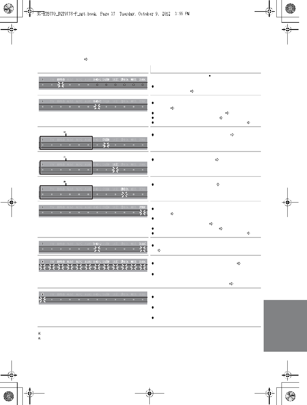
Indicator illumination
The indicators display the condition of this unit by flashing. The indicator patterns illustrated below are
displayed during normal operational conditions. They do not refer to the indications of a problem. Refer
to Troubleshooting ( 33) if the indicators do not light up as illustrated below.
1 Th e sele cted source i ndicator will also light.
2 The BD/DVD indicator stops blinking and ligh ts on ce the wireless pairing is successful.
Indicator Description
The BD/DVD indicator blinks 2 and sound mode
indicators light up in sequence for 1 minute.
When the mai n unit is in wireless pa iring mode wi th the
active subwoofer ( 35)
The indicator blinks for 20 sec.
When 3D sur round e ffect and cle ar-mod e dialog effect
ar e on ( 32)
When the dual audi o setti ng is Main ( 31)
When the auto gain contro l is on ( 31)
When the Bluetooth® communication is mode 1 ( 31)
The indicators blink for 5 sec.
When the audio format is Dolby Digital ( 31)
The indicator blinks for 5 sec.
When the audio format is DTS ( 31)
The indicators blink for 5 sec.
When the audio format is PCM ( 31)
The indicator blinks for 20 sec.
When 3D sur round e ffect and cle ar-mod e dialog effect
are off ( 32)
When the dual audi o setti ng is Secondary (SAP:
Secondar y Audi o Program) ( 31)
When the auto gain control is off ( 31)
When the Bluetooth® communication is mode 2 ( 31)
The indicators blink for 20 se c.
When the dual audi o setting is Main and Secon dary
(31)
The indicators blink for 10 sec.
When the remote con tr ol cod e is changed ( 32)
The indicators blink once.
When changing the setting (To reduce the cl ear -mod e
di alo g e ff ect, To turn o ff VIE RA Lin k HDAVI Cont ro l,
and To turn off the volume limi tatio n) ( 32)
Bluetooth® indicator blinks quickly.
When the ma in un it is re ady for pairin g
Bluetooth® indicator blinks slowly.
When the ma in un it is waiti ng to connect
Bluetooth® indicator turns on.
When the main unit is connected with a Bluetooth ®
device
38 R QT 97 78
Limited Warranty
(ONLY FOR U.S.A. AND PUERTO RICO)
Panasonic Consumer Marketing Company of North America,
Division of Panasonic Corporation of North Am erica
One Panasonic Way, Secaucus, New Jersey 07094
Panasonic Products Limited Warranty
Limited Warranty Coverage
(For USA and Puerto Rico Only)
If your product does not work prop erly be cause of a defect in materials or
workmanship, Pana sonic Consumer Marketing Company of North Am erica
(referred to a s the warranto r) will, for the length of the period indicated o n
the chart belo w, which starts with the date of original purchase (warranty
period), at its option either ( a) repair your p roduct with new or refurbished
parts, (b) replace it with a new or a re furbished equivalent value pro duct, or
(c) refund your purchase price. The decision to repair, replace or refund will
be made by th e warrantor.
During the La bor warranty period the re will be no charge for labor. During
the Parts w arranty period, there will be no charge for parts. This Lim ited
Warranty excludes both parts and labor for n on-rechargeable batteries,
antenna s, and cosmetic parts (cabinet). This w arranty only applies to
products purch ased and serviced in the U nited States or Pu erto R ico. T his
warranty is extended only to the original p urchaser of a new product which
was not sold as is.
Mail-In Service
Fo r assistance in the U.S.A. and Puerto Rico in o btaining repairs, ple ase
ship t he product prepaid to:
Pana sonic Exchange Center
4900 George McVay Drive
Suite B
McA llen, TX 78503
pan acare@u s.panasonic.com
Online Repair Request
To sub mit a new repair requ est and for qu ick repair status visit our Web Site
at www.panasonic.com/repair.
When shipping the unit, carefully pack, include all supplied accesso ries listed
in the Owners Manua l, and send it prepaid, adequately insured and packed
well in a carton box. When shippin g Lithium Ion batteries please visit our
Web Site at www.pan ason ic.com/BatteryHa ndling as Panasonic is
committed to providing the most up to date informat ion. Include a letter
detailing the comp laint, a return address and pro vide a daytime phone
number where you can be re ached . A valid registered receipt is required
under the Limited Warranty.
IF REPAI R IS NEEDED DURING THE WARRANTY PERIOD, THE
PURCHASER WILL BE REQUIRED TO FURNISH A SALES RECEIPT/
PROOF OF PURCHASE INDICATING DATE OF PURCHASE, AMOUNT
PAID AND PLACE OF PURCHASE. CUSTOMER WILL BE CHARGED
FOR THE REPAIR OF ANY UNIT RECEIVED WITHOUT SUCH PROOF
OF PURCHASE.
Limited Warranty Limits And Exclusions
Th is warranty ONLY COVER S failures due to defects in m aterials or
workmanship, a nd DOES NOT COVER normal wear and tear or cosmetic
damage . The warran ty ALSO DOES N OT COVER damages which occurred
in shipment , or failures which are caused by products not supplied by the
warranto r, or failures which result from accidents, misuse, abuse, neglect,
mishandling, misapplication, alteration, faulty installa tion,
set-up adjustments, misadjustment of con sumer controls, improper
maintenance, pow er line su rge, lig htning damage, mo dification, introduction
of sand, humidity or liquids, commercial u se such a s hotel, office, restaurant,
or other bu siness or rental use of th e product, or service by anyone other
than a Factory Service Center or oth er Authorized Servicer, or damage that
is attributable to acts of God.
THERE ARE NO EXPRESS WARRANTIES EXCEPT AS LI STED
UNDER LIMITED WARRANTY COVERAGE.
THE WARRANTOR IS NOT LIABLE FOR INCIDENTAL OR
CONSEQUENTIAL DAMAGES RESULTING FROM THE USE OF THIS
PRODU CT, OR ARISIN G OUT OF AN Y BREACH OF THI S
WAR RA NT Y.
(As examples, this excludes dama ges for lost time, travel to and fro m the
servicer, loss of or damage to media or ima ges, d ata or oth er mem ory or
re corded content. The items listed are not exclusive, but for illustration only.)
ALL EXPRESS AND IMPLIED WARRANTIES, INCLUDING THE
WARRANTY OF MERCHANTABILITY, ARE LIMITED TO THE PERIOD
OF THE LIMITED WARRANTY.
Some states do not allow the exclu sion or limitation of incidental or
consequential dama ges, or limitations on how lo ng a n implied warranty lasts,
so the exclusions may no t apply to you.
Th is warranty gives you specific le gal rig hts and you m ay also have other
rights which vary from state to state. If a prob lem w ith th is product d evelops
during or after the warrant y perio d, yo u may contact your deale r or Service
Center. If the proble m is not handled to you r satisfaction, then write to the
warrant ors Consumer Affairs Department at the addresses listed for the
warrant or.
PARTS AND SERVICE, WHICH ARE NOT COVERED BY THIS
LIMITED WARRANTY, ARE YOUR RESPONSIBILITY.
As of October 2012
Product or Part Name Parts Labo r
Home Theater Audio System 1 year 1 yea r
All included Accessories
(Except Non-Rechar geable Batteries) 90 days Not
Applicable
Only Non-Rechar geable Batteries 10 days Not
Applicable
Cust omer S er vi ce s Direc tor y (Un it ed St ate s and Pue rto Ri co)
Obtain Product Information and Operating Assistance; loc ate
your nearest Dealer or Serv ice Cente r; purchase Parts and
Acces sori es; or mak e Customer Servic e and Literat ure reque sts
by visiting our We b Si te at:
http://www.panasonic.c om/help
or, contact us via the web at:
http://www.panasonic.c om/contactinfo
You m ay a lso contact us directly at:
1-800-211-PANA (72 62)
Monday-Friday 9am-9pm,
Saturday-Sunday 10am-7pm EST
For hea ring or speech impaired TTY users, TTY: 1-8 77-833- 885 5
Ac ce ss ory P urcha se s (Unit ed St ate s and Pu ert o Rico )
Purchase Parts, Accessories and Instruction Books online for all
Panasonic Products by visitin g our Web Site at:
http://www.pstc.pan asonic.com
Or, send yo ur request by E-mail to:
npcparts@u s.panasoni c.com
You m ay a lso contact us directly at:
1-800-332-5368 (Phone) 1-800-237-9080 (Fax On ly)
(M onday-Friday 9 am-9pm EST )
Panasonic National Parts C enter
20421 84th Ave S., Ken t, WA 980 32
(We a ccept Visa, M asterCard, Discover Card, Ame rican Express)
For hea ring or speech impaired TTY users, TTY: 1-8 66-605- 127 7
The mod el nu m be r a nd s erial nu m be r of t his pro du ct can b e
found on either the back or the bottom of the unit.
Please note them in the space provided below and keep for future
r ef er e nce .
MODEL NUMBER SC-HTB77 0
SERIAL NUMBER
Us er me mo:
DATE OF PURCHASE ______________________________
DEALER NAME ___________________________________
DEALER ADDRESS________________________________
_________________________________________________
TELEPHONE NUMBER _____________________________
RQT9778 39
Limited Warranty (
ONLY FOR
CANADA)
Panasonic Canada Inc.
5770 Ambler Drive, Mississauga, Ontario L4 W 2T3
PANASONIC PRODUCT - LIMITED WARRANTY
Pana soni c Canad a Inc. war rants this pro duct to be free from defects in material a nd workmanship unde r normal use
and for a period as stated below fro m the date of original purch ase agrees to, at i ts option either (a) repair your produ ct
with new or refurbishe d parts, (b) replace it with a new or a re furbi shed equ ivalent value p roduct, or (c) r efund your
purchase price. The decision to repair, r eplace o r refund will be made by Pana sonic Can ada Inc.
Technics Audio Product - One (1) year, parts and labour
Panasonic BD/DVD Product - One (1) year, parts and labour
Panasonic Audio Receivers - One (1) year, parts and labour
Home Theat er S ys tems Product - One (1) year, parts and labour
This war ranty is given only to the or igina l pur chaser, or the person for wh om it was purcha sed as a gi ft, of a Panasonic
br and prod uct mentio ned above sold by an authorized Panasonic dealer in C anada and pu rchased a nd use d in
Can ad a, which pro du ct was no t sold as is, and which pro du ct was delive red to yo u in new condi tion in the origi nal
packaging.
IN ORDER TO BE ELIGIBLE TO RECEIVE WARRANTY SERVICE HEREUNDER, A PURCHASE RECEIPT OR
OTHER PROOF OF DATE OF ORIGINAL PURCHASE, SHOWING AMOUNT PAID AND PLACE OF PURCHASE IS
REQUIRED
LIMITATIONS AND EXCLUSIONS
This war ranty ONLY COVERS failures du e to defects in mater ials or workmansh ip, and DOES NOT COVER normal
wea r and te ar or cosmetic damage. The warran ty ALSO DOES NOT COVER damages which occu rred i n shipment, or
failures whi ch are caused b y products not supplied by Panasonic Canada I nc., or failur es which result from accidents,
misuse, abuse, negl ect, m ishandling, mi sapplicatio n, alteration, faulty installati on, set-u p adjustments, misadj ustment of
consumer controls, impr ope r maintenance, power line surge, lightning damage , modification, introd uction of sand,
humidi ty or liquids, commercial use such as hotel, office, restauran t, or other busine ss or rental u se of the product, or
service by anyone other than a n Authorized Servicer, or damag e that is attributable to acts of God.
Dry cell batteries ar e also excluded fr om coverage u nder this warr anty.
THIS EXPRESS, LIMITED WARRANTY IS IN LIEU OF ALL OTHER WARRANTIES, EXPRESS OR IMPLIED,
INCLUDING ANY IMPLIED WARRANTIES OF MERCHANTABILITY AND FITNESS FOR A PARTICULAR PURPOSE.
IN NO EVENT WILL PANASONIC CANADA INC. BE LIABLE FOR ANY SPECIAL, INDIRECT OR CONSEQUENTIAL
DAMAGES RESULTING FROM THE USE OF THIS PRODUCT OR ARISING OUT OF ANY BREACH OF ANY
EXPRESS OR IMPLIED WARRANTY. (As examples, this warranty excludes damages for lost time, travel to and from
the Authorized Servicer, loss of or damage to media or images, data or other mem ory or re corded content. This list of
items is not exhaustive, but for illustration only.)
In certain i nstances, some jurisdictions do not a llow the exclusion or li mitati on of incidental or conseque ntial damages,
or the exclusio n of implied war rantie s, so the a bove li mitations and exclusions ma y not b e applicable . This warran ty
gi ves you specific legal rights a nd you m ay h ave other rights which vary d ep end ing on your provi nce or ter ritory.
WARRANTY SERVICE
For product operation and information assistance, please contact:
PRODUCT OPERATION ASSISTANCE
Customer Care Centre : Telephone #: 1-8 00- 561-5505
Fax #: (90 5) 238-2360
Email link: Supp ort contact us emai l on www.p anasoni c.ca
PRODUCT REPAIRS
Pl ease lo cate your n ea rest Authorized Servicentre .
Lin k: Sup por t Panasonic Servicentre ® loca tor on www.pan asoni c.ca
IF YOU SHIP THE PRODUCT TO A SERVICENTRE
Car efully pa ck and sen d pr epa id, adequately insured and pr efera bly in the origi nal carton.
Inclu de details of th e defect claime d, and p roof o f date of o rigina l purchase.
RQT9778-P
F1212R K0
-If you see this symbol-
Information on Disposal in other Countries outside the
European Union
This symbol is only valid in the European Union.
If you wish to discard this product, please contact
your local authorities or dealer and ask for the
correct method of disposal.