Panasonic of North America 11BT1301 Transmitter Module User Manual OI Manual SC HTB770 RQT9778 P 121012
Panasonic Corporation of North America Transmitter Module OI Manual SC HTB770 RQT9778 P 121012
Contents
- 1. OI Manual_SC-HTB370_RQT9777-P_121011
- 2. OI Manual_SC-HTB770_RQT9778-P_121012
OI Manual_SC-HTB770_RQT9778-P_121012
Owners Manual
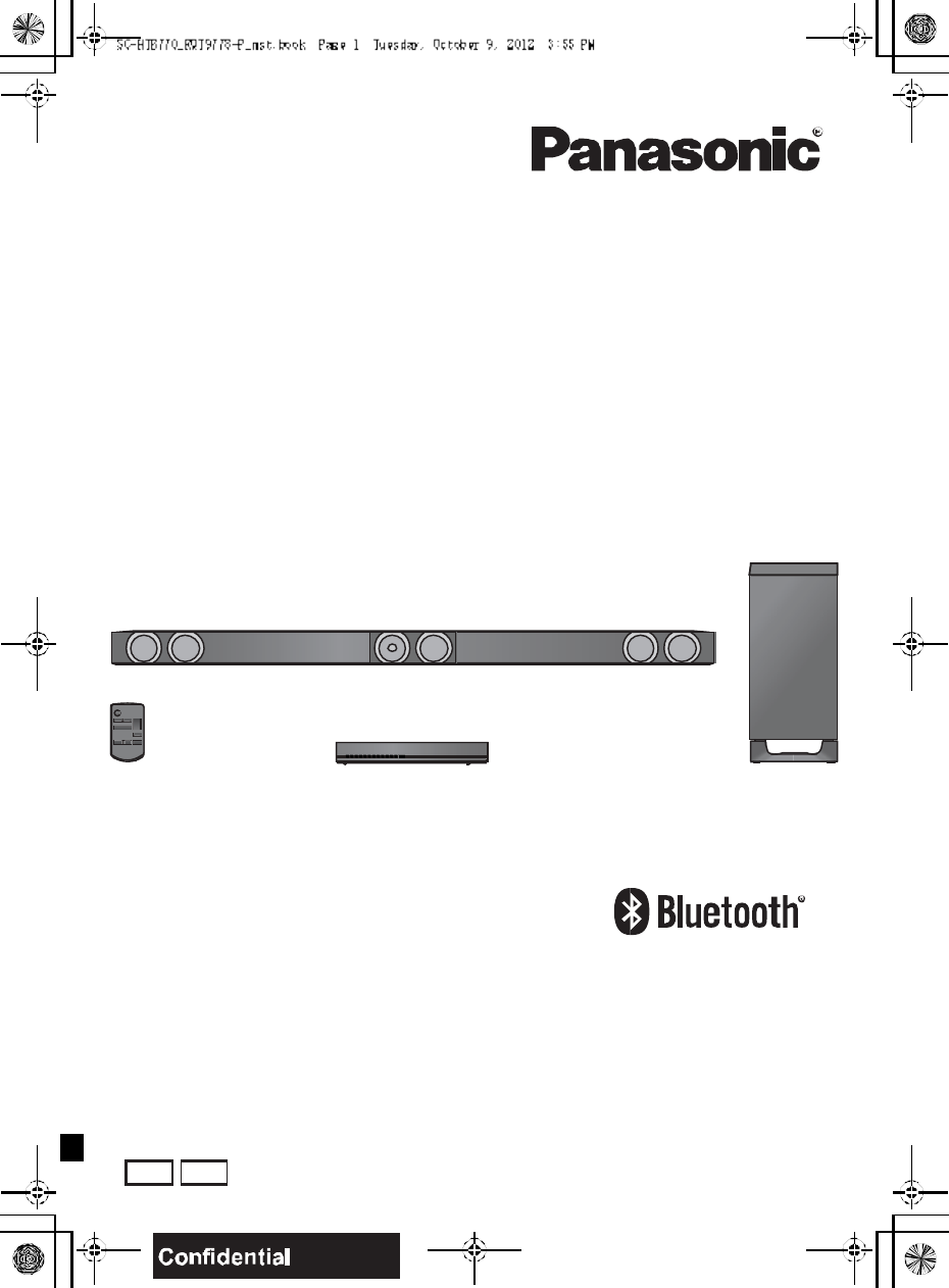
Home Theater Audio System
Model No. SC-HTB770
Thank you for purchasing this product.
Please read these instructions carefully before using this product,
and save this manual for future use.
If you have any questions, contact:
U.S.A. and Puerto Rico: 1-800-211-PANA (7262)
Canada: 1-800-561-5505
RQT9778-P
2R QT977 8
IMPORTANT SAFETY INSTRUCTIONS
Read these operating instructions carefully before using the unit. Follow the safety instructions on the
unit and the applicable safety instructions listed below. Keep these operating instructions handy for
future reference.
1 Read these instructions.
2 Keep these instructions.
3 Heed all warnings.
4 Follow all instructions.
5 Do not use this apparatus near water.
6 Clean only with dry cloth.
7 Do not block any ventilation openings. Install in
accordan ce with the manufacturer s instructions.
8 Do not install near a ny heat sources such as
radiators, heat registers, stoves, or other apparatus
(including amplifiers) that produce heat.
9 Do not defeat the safety purpose of the polarized or
grounding-type plug. A polarized plug has two blades
with one wider than the o ther.
A grounding-type plug has two blades and a third
grounding prong. The wide blade or the thi rd prong
are provided for your safety. If the provided plug does
not fit into your outlet, consult a n electri cian for
replacement of the obsolete outlet.
10 Protect the power cord fro m being walked on or
pinched pa rticularly at plugs, convenience
receptacles, and the point where they exit from the
apparatus.
11 Only use attachments/accessories sp ecified by the
manufacturer.
12 Use only with the cart, stand, tripod,
bracket, or table specified by the
manufacturer, or sold with the
apparatus. When a cart is used, use
caution when moving the cart/
apparatus combination to avoid injury
from tip-over.
13 Unplug thi s apparatu s during lightning storms or
when unu sed for long periods of time.
14 Refer all servicing to qualified service personnel.
Servicin g is required when the apparatus has been
damaged in any way, such as power-supply cord or
plug is damaged, liquid has been spilled or objects
have fallen into th e apparatus, the apparatus has
been exposed to rain or moisture, does not operate
normally, or has been dropped.
Unit
To reduce the risk of fire, electric shock or product
damage,
Do not expose this unit to rain, moisture, dripping or
splashing .
Do not place objects filled with liquids, such a s vases,
on this un it.
Use only the recommended accessories.
Do not re move covers.
Do not repa ir this unit by yourself. Refer servicing to
qualified service personnel.
Power cord
Install this unit so that the power cord can be unpl ugged
from the socket outlet immediately if any problem
occurs.
Button-type battery (Lithium battery)
Risk of fire, explosion and burns. Do not di sassemble,
heat above 60 oC (140 oF) or incinerate.
WARNING
DO NOT INGEST BATTERY,
CHEMICAL BURN HAZARD
This product contains a coin/button cell battery. If the
coin/button cell battery is swallowed, it can cause
severe internal bu rns in just 2 hours and can lead to
death. Keep new and used batteries away from
children. If the battery compartment does no t close
securely, stop using the product and keep it away from
children. If you think batteries might have been
swallowed or placed inside any par t of the body, seek
immediate med ical attention.
If any electrolyte should come into contact with your
hands or clothes, wash it off thoroughly with water.
If any electrolyte should come into contact with your
eyes, never rub the eyes. Rinse eyes thoroughly wi th
water, and then consult a doctor.
<For USA-California o nly>
This product co ntains a CR Coin Cell Lithium Battery
which contains Perchlorate Material special handling
may apply.
See www.dtsc.ca.gov/hazardouswaste/perchlorate.
R QT977 8 3
Unit
Do not pl ace sour ces of naked flames, such as lighted
candles, on this unit.
Placement
To reduce the risk of fire, electric shock o r product
damage,
Do not install or place this unit in a bookcase, built-in
cabinet or in an other confined space. Ensure this unit
is well ventilated.
Do not o bstruct this units ve ntilation openings with
newspapers, tablecloths, curtains, and similar items.
Button-type battery (Lithium battery)
Danger o f explosion if battery is incorrectly replace d.
Replace only with the type recommended by the
manufacturer.
Keep out of reach of child ren.
Insert with poles aligned.
Mishandling of b atteries can cause electrolyte leakage
and may cause a fire.
Remove the battery if you do not intend to use the
remote control for a long period of time. Store in a
cool, dark place.
Do not heat or expose to flame.
Do not leave the battery(ies) in a car exp osed to
direct sunlight for a long p eriod of time with doors and
windows closed.
Do not touch the terminals ( and ) with metal
objects.
Do not r echarge, disassemble, remodel, heat or
throw into fire.
When disposing the batteries, please contact yo ur local
authoritie s or dealer and ask for the correct method of
disposal.
CAUTION
THE FOLLOWING APPLIES ONLY IN THE
U.S.A.
FCC Note:
This equipment has been tested and found to comply with
the limits for a Cla ss B digital dev ic e, p urs uan t to Pa rt 15
of the FCC Rules.
These limits are designed to provide reasonable
protection against harmful interference in a residential
installation. This equipment generates, uses and can
radiate radio frequency energy and, if not installed and
used in accordance with the instructions, may cause
harmful interference to radio communications.
However, there is no guarantee that interference will not
occur in a particular installation. If this equipment does
cause harmful interference to radio or television reception,
which can be determined by turning the equipment off and
on, the user is encouraged to try to correct the
interference by one or more of the following measures:
Reorient or relocate the receiving antenna.
Increase the separation between the equipment and
receiver.
Connect the equipment into an outlet on a circuit
different from that to which the receiver is connected.
Consult the dealer or an experienced radio/TV
technician for help.
Any unauthorized changes or modifications to this
equipment would void the users authority to operate this
d ev i ce.
This device complies with Part 15 of the FCC Rules.
Operation is subject to the following tw o conditions:
(1) This device may not cause harmful interference, and
(2) this device must accept any interference received,
including interference that may cause undesired
operation.
Responsible Party:
Panasonic Corporation of North America
One Panasonic Way,
S ec au cu s, NJ 07 0 94
Support Contact:
Panasonic Consumer Marketing Company of
North America
Telephone No.: 1-800-211-PANA (7262)
THE FOLLOWING APPLIES ONLY IN
CANADA.
This device complies with RSS-GEN, RSS-210 of the IC
Rules. Operation is subject to the following two conditions:
(1) This device may not cause harmful interference,
(2) This device must accept any interference received,
including interference that may cause undesired operation
of the device.
THE FOLLOWING APPLIES IN THE U.S.A.
AND CANA DA
This transmitter must not be co-located or operated in
conjunction with any other antenna or transmitter.
This equipment complies with FCC/IC radiation exposure
limits set forth for an uncontrolled environment and meets
the FCC radio frequency (R F) Exposure Guidelines in
Supplement C to OET65 and RSS-102 of the IC radio
frequency (RF) Exposure rules. This equipment has very
low levels of RF energy that is deem ed to comply without
maximu m permi ssiv e ex po su r e ev alua ti o n (M P E ). B ut it is
desirable that it should be installed and operated keeping
the radiator at least 20 cm (7 7
/8)or more away from
persons body (excluding extremities: hands, wrists, feet
and ankles).
4R QT977 8
Unit care
Clean this unit with a soft, dry cloth
When dir t is heavy, wring a cloth moistened in water
tightly to wipe the dirt, and then wip e it with a dry cloth.
When cleaning this unit, use a fine cloth. Do not use
tissues or other materials (towels, etc.) that can fall
apart. Small grains may get stuck inside the speaker
cover.
Never use alcohol, paint thinner or benzine to clean this
unit.
Before using chemically-treated cloth, carefully read the
instructions that came with the cloth.
About Bluetooth®
Frequency band used
This unit uses the 2.4 G Hz frequency band.
Certification of this device
This unit conforms to freq uency r estrictions and has
received certification based on frequency laws. Thus, a
wireless permit is not necessary.
The actio n below are punishable by law in some
countries:
Taking apart or mod ifying the unit.
Removing specification indications.
Restrictions of use
Wireless transmission and /or usag e with all Bluetoo th®
equipped device s is not guaranteed.
All devices must conform to standards set by Bluetooth
SIG, Inc.
Depending on the specifications and settin gs of a
device, it can fail to connect or some operations can be
different.
This unit supports Bluetooth® security features. But
depending on the operating environment a nd/or
settings, this security is p ossibly not sufficient. Transmit
data wirelessly to this unit with caution.
This unit cannot transmit data to a Bluetooth® device.
Range of use
Use this device at a maximum range of 10 m (33 ft).
The range can decrease depending on the enviro nment,
obstacles or interference.
Interference from other devices
When other devices use the same frequency as this
unit,this unit may operate inco rrectly or the sound may
be distorted.
To prevent interference from other devices:
Keep this unit away from other devices that emit
radio freq uency interference.
Do not use this system and a wireless LAN device at
the same time. Switch off any wireless LAN de vice.
Intended usage
This unit is for normal, gen eral use only.
Do not use this unit near an equipment or in an
environment that is sensitive to radio frequency
interferen ce (example: airports, hospitals, laboratories,
etc).
Manufactured under license from Dolby Laboratories.
Dolby, Pro Logic, and the double-D symbol are trademarks
of Dolby Laboratories.
Manufactured under license under U.S. Patent Nos:
5,956,674; 5,974,380; 6,487,535 & other U.S. and
worldwide patents issued & pending.
DTS, the Symbol, & DTS and the Symbol together are
registered trademarks & DTS Digital Surround and the DTS
logos are trademarks of DTS, Inc. Product includes
software.
© DTS , I nc . All Rig hts Reserved.
HDMI, the HDMI Logo, and High-Definition Multimedia
Interface are trademarks or registered trademarks of HDMI
Licensing LLC in the United States and other countries.
HDAVI Control is a trademark of Panasonic Corporation.
VIERA Link is a trademark of Panasonic Corporation.
EZ Sync is a trademark of Panasonic Corporation.
The Bluetooth® word mark and logos are owned by the
Bluetooth SIG, Inc. and any use of such marks by
Panasonic Corporation is under license. Other trademarks
and trade names are those of their respective owners.
Panasonic bears no responsibility for data
and/or information that is compromised
during a wireless transmission.
R QT977 8 5
Table of contents
IMPORTANT SAFETY INSTRUCTIONS .......................................................................... 2
Unit care ........................................................................................................................... 4
About Bluetooth®............................................................................................................. 4
Table of contents ............................................................................................................. 5
Before use
Supplied items ................................................................................................................. 6
This unit (SC-HTB770) ............................................................................................................... 6
Accessories................................................................................................................................ 6
Control reference guide .................................................................................................. 7
This unit (Front).......................................................................................................................... 7
This unit (Rear) .......................................................................................................................... 8
Remote control ........................................................................................................................... 9
Getting started
Step 1 Selecting the placement method ..................................................................... 10
The speaker system ................................................................................................................. 11
The active subwoofer ............................................................................................................... 11
Wireless interference ............................................................................................................... 11
Step 2 Assembling the speakers................................................................................. 12
When attaching the speakers to a wall .................................................................................... 12
When placing the speakers on a table..................................................................................... 18
Additional speaker fall prevention measures ........................................................................... 22
Step 3 Connections ...................................................................................................... 24
Connection with the TV ............................................................................................................ 24
Connection with other devices ................................................................................................. 25
Speaker cable connection ........................................................................................................ 26
AC power supply cord connection............................................................................................ 26
Active subwoofer wireless connection ..................................................................................... 27
Bluetooth® connection.............................................................................................................. 27
Operations
Using this unit................................................................................................................ 28
3D sound ........................................................................................................................ 29
Audio output modes ................................................................................................................. 29
Linked operations with the TV
(VIERA LinkTMHDAVI ControlTM).......................................................................... 30
Advanced operations .................................................................................................... 31
Reference
Troubleshooting............................................................................................................. 33
Specifications ................................................................................................................ 35
Indicator illumination..................................................................................................... 37
Limited Warranty
(ONLY FOR U.S.A. AND PUERTO RICO) ................................................................. 38
Limited Warranty (ONLY FOR CANADA)..................................................................... 39
6R QT977 8
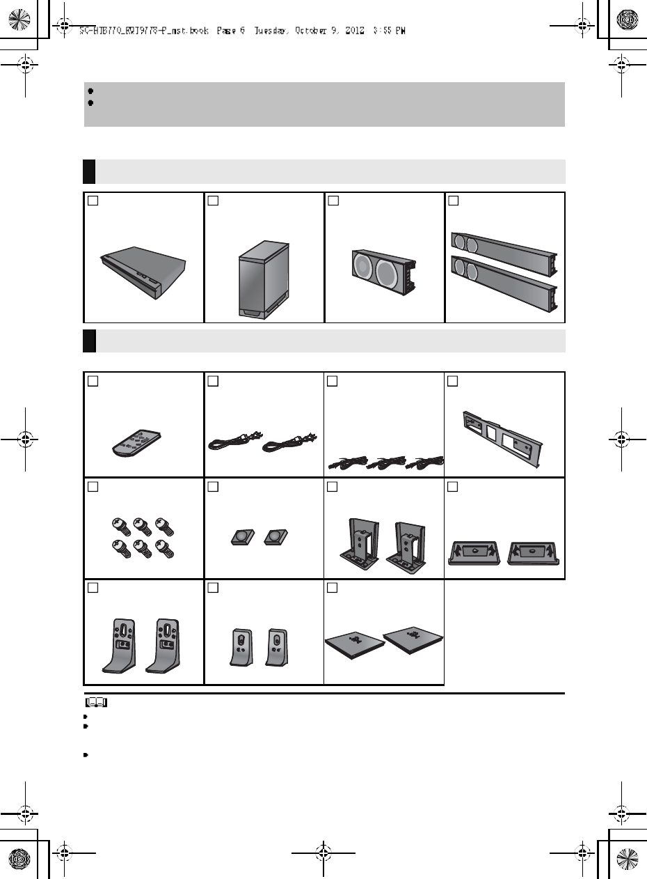
Supplied items
Check the supplied accessories before using this unit.
Product numbers are correct as of December 2012. These may be subject to change.
For U.S.A. and Puerto Rico:
To order accessories, refer to Accessory Purchases (United States and Puerto Rico) on page 38.
For Canada: To order accessories, call the dealer from whom you have made your purchase.
The supplied AC power supply cord is for use with this unit only.
Do not use it with other equipment. Also, do not use cords from other equipment with this unit.
The illustrations shown may differ from your unit.
Operations in this Owners Manual are described mainly with the remote control, but you can
perform the operations on the main unit if the controls are the same.
This unit (SC-HTB770)
1 Main unit
(SU-HTB770)
1 Active
sub woofer
(SB-HWA770)
1Center speaker
(SB-HTB770)
2 Front speakers
(SB-HTB570)
Accessories
1 Remote co ntrol
(with a battery)
(N2QAYC000083)
2 AC power supply
cords
(K2CB2YY00084)
3Speaker cables
(REEX1266A: RED)
(REEX1267A: WHITE)
(REEX1268: GREEN)
Length: 3 m (9.8 ft)
1Metal bracket
(RML0760A)
6 Screws
(XYN5+J14FJK)
2 Speaker feet
(RKAX0042-K)
2Stand necks
(RGK2444)
2Side caps
(RGK2445: R)
(RGK2446: L)
2Leg stands
(RGK2463)
2 Su pport legs
(RGK2464)
2 Speaker bases
(RGK2465)
(O NLY FOR CANADA)
The enclosed French
Canadian label sheet
corresponds to the
English display on the
remote control and the
top and rear of the main
unit and active
subwoofer.
R QT977 8 7
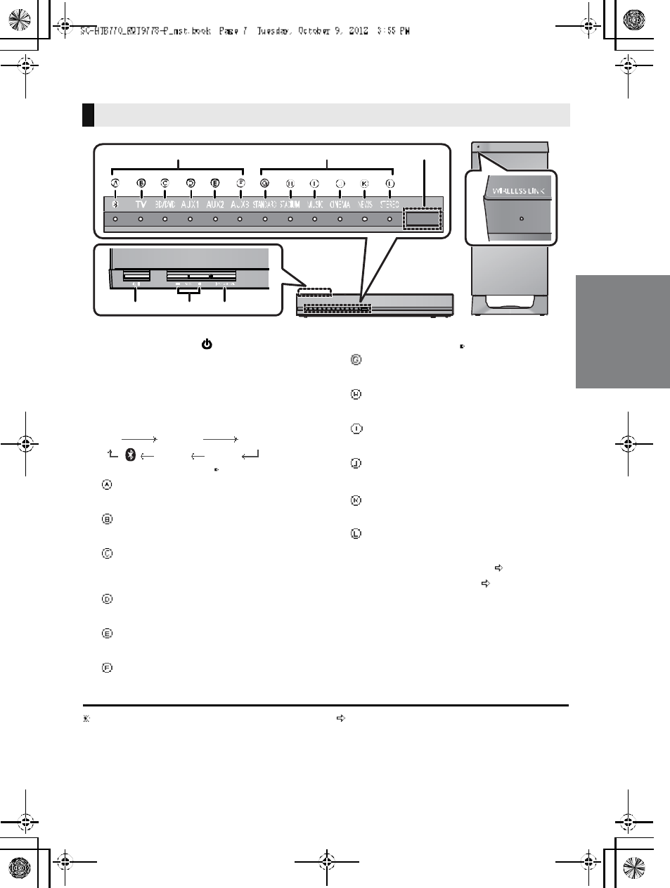
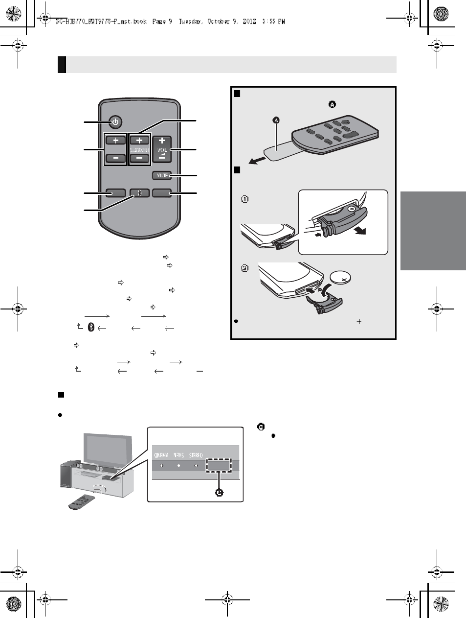
Control reference guide
1Standby/on switch ( /I)
Press to switch the main unit from on to
standby mode or vice versa. In standby mode,
the main unit is still consuming a small amount
of power.
2 Adjust the volume of this unit
3 Select the input source
TVBD/DVDAUX1
AUX3 AUX2
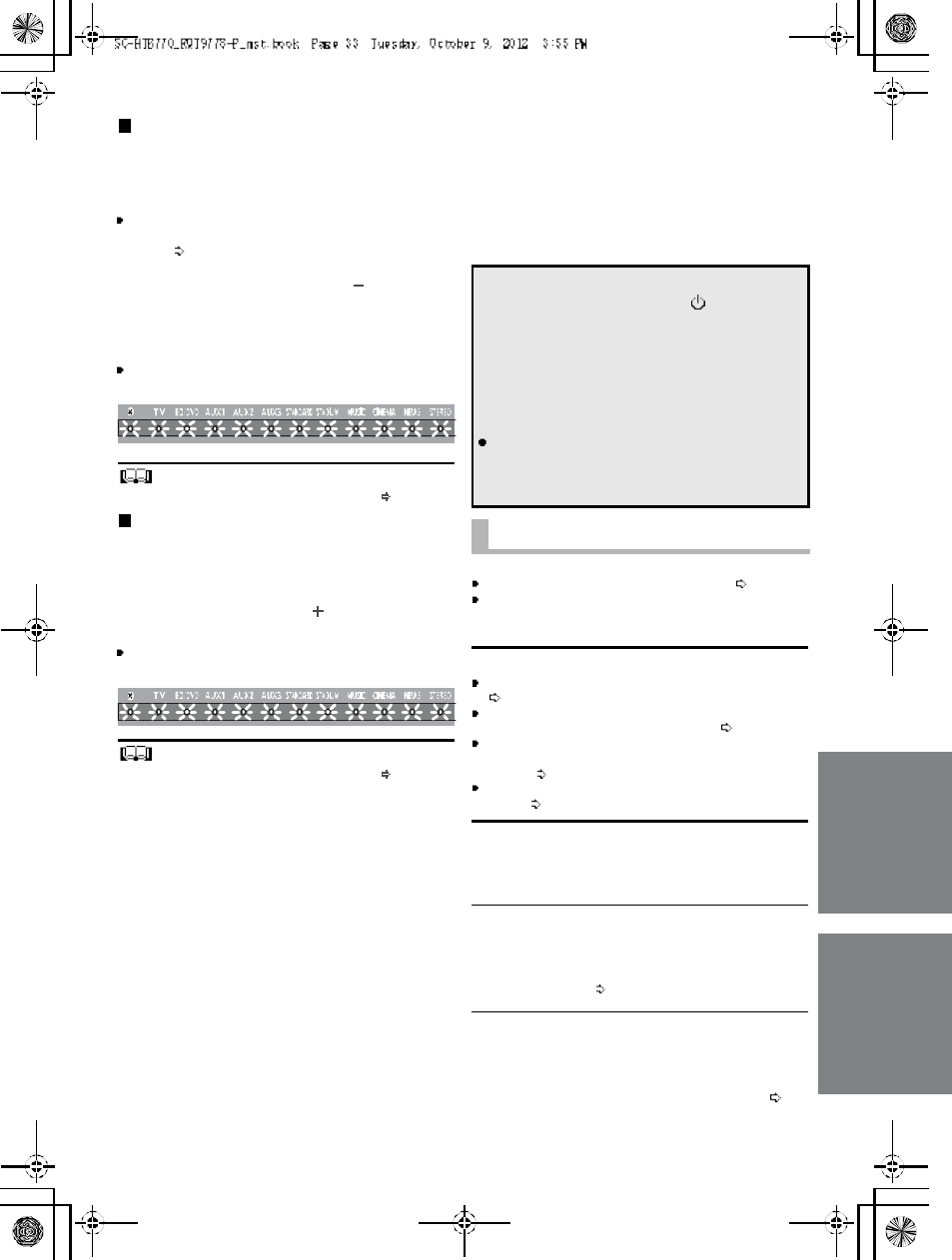
4 Input selector indicators
Bluetooth® indicator
Lights blue when the Bluetooth® device is
the audio source
TV indicator
Lights green when the TV is the audio
source
BD /DVD i n di cator
Lights amber when the device connected
to the BD/DVD terminal is the audio
source
AUX1 indicator
Lights amber when the device connected
to the AUX1 terminal is the audio source
AUX2 indicator
Lights amber when the device connected
to the AUX2 terminal is the audio source
AUX3 indicator
Lights amber when the device connected
to the AUX3 terminal is the audio source
5Sound mode indicators
STANDARD indicator
Lights when STANDARD is the current
sound mode
STADIUM/Dolby
® Digital indicator
Lights when STADIUM is the current
sound mode
MUSIC/DTS indicator
Lights when MUSIC is the current sound
mode
CINEMA/PCM indicator
Lights when CINEMA is the current sound
mode
NEWS indicator
Lights when NEWS is the current sound
mode
STEREO indicator
Lights when STEREO is the current sound
mode
6 Remote control signal sensor ( 9)
7 WIRELESS LINK indicator ( 27)
The indicators will also blink in various conditions ( 37)
To indicate the current audio format, refer to page 31 (Audio format indicator)
This unit (Front)
7
123
4 56
M a in un it
Active subwoofer
8R QT977 8
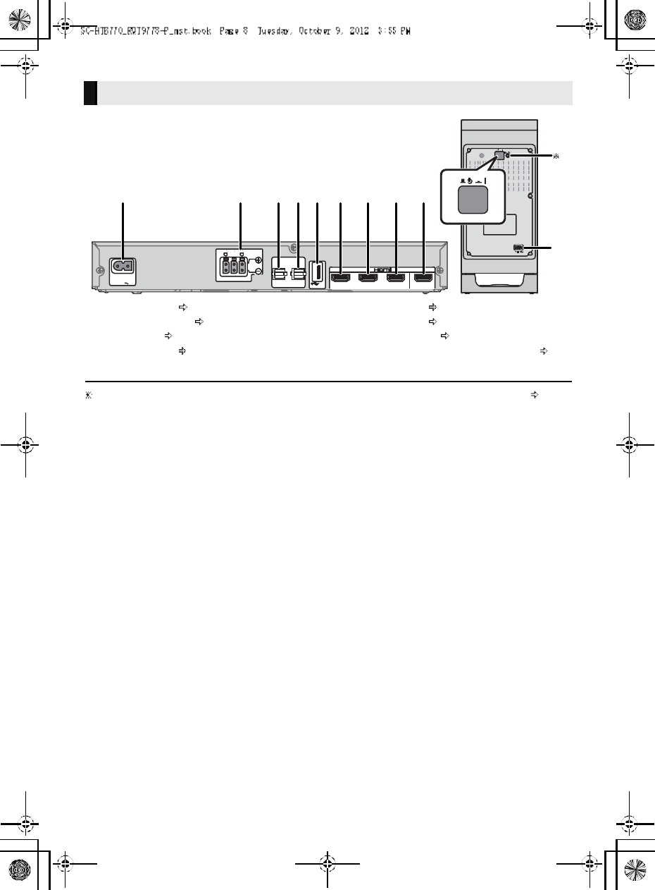
1 AC IN terminal ( 26)
2 Speaker terminals ( 26)
3 TV terminal ( 24)
4 AUX3 terminal ( 25)
5 USB port (for service use only)
6 AUX2 terminal ( 25)
7 AUX1 terminal ( 25)
8 BD/DVD terminal ( 25)
9 HDMI OUT terminal (ARC compatible) ( 24)
10 Active subwoofer on/off button
The I/D SET button is only used when the main unit is not paired with the active subwoofer ( 35)
This unit (Rear)
A C IN A V IN TV (ARC)
BD/DVDBD/DVDAUX1
(H D M I1)(HDMI2)
AUX2
(HDMI3)
AV OU T
D IGITA L
A U DIO
IN
TV
(O PT 1)
AUX3
(O PT2 )
SPEAKERS/HAUT-PARLEURS
66 6
R
CEN TER
FOR
SER VICE ON LY
12 3 4 5 6 7 8 9
10
1
R QT977 8 9
1 Turn the main unit on or off ( 28)
2 Adjust the dialog effect level ( 28)
3 Adjust the output level of the active subwoofer
(bass sound) ( 28)
4Adjust the volume of this unit (28)
5 Mute the sound ( 28)
6 Select the input source ( 28)
TVBD/DVDAUX1
AUX3 AUX2
7 Select the Bluetooth® device as the source
(28)
8 Select the sound mode ( 28)
STANDARDSTADIUMMUSIC
STEREO NEWS CINEMA
Remote control
Before using for the first time
Remove the insulation sheet .
To replace a button-type battery
Battery type: CR2025 (Lithium battery)
Set the button-type battery with its ( ) mark
facing upward.
Remote control operation range
The remote control signal sensor is located on the main unit.
Use the remote control within the correct operation range.
Remote control signal sensor
Operation rang e
Distance: Within approx. 7 m
(23 ft) directly in front
Angle: Approx. 30o
left and right
10 R QT977 8
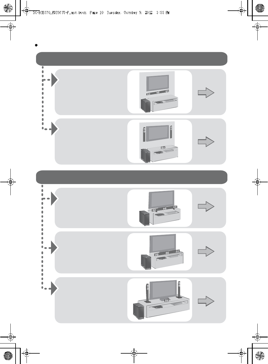
Step 1 Selecting the placement method
Choose a placement method that suits you best.
When attaching the speakers to a wall
When placing the speakers on a table
Place the speakers
horizontally
Page 12
Place the front speakers
vertically
Place the speakers using
the leg stands
Place the front speakers
using the speaker bases
Page 15
Page 18
Page 19
Page 20
Place the speakers
using the support legs
and speaker feet
R QT977 8 11
Use a screwdriver ( ) for assembling the speakers.
Do not hold the speakers in one hand to avoid injury, you may drop the speakers when carrying them.
When carrying the active subwoofer
To avoid interference, maintain the following distances between the main unit/active subwoofer
and other electronic devices that use the same radio frequency (2.4 GHz band).
Place the active subwoofer within a few meters of the main unit and in a horizontal position with the top panel faced upward.
Do not use this unit in a metal cabinet.
Placing the active subwoofer too close to the walls and corners can result in excessive bass. Cover walls and windows with
thick curtains.
If irregular coloring occurs on your TV, turn the TV off for about 30 minutes. If it persists, move the speakers further away from
the TV.
Keep magnetized items away. Magnetized cards, watches, etc., can be damaged if placed too close to the active subwoofer
and the speakers.
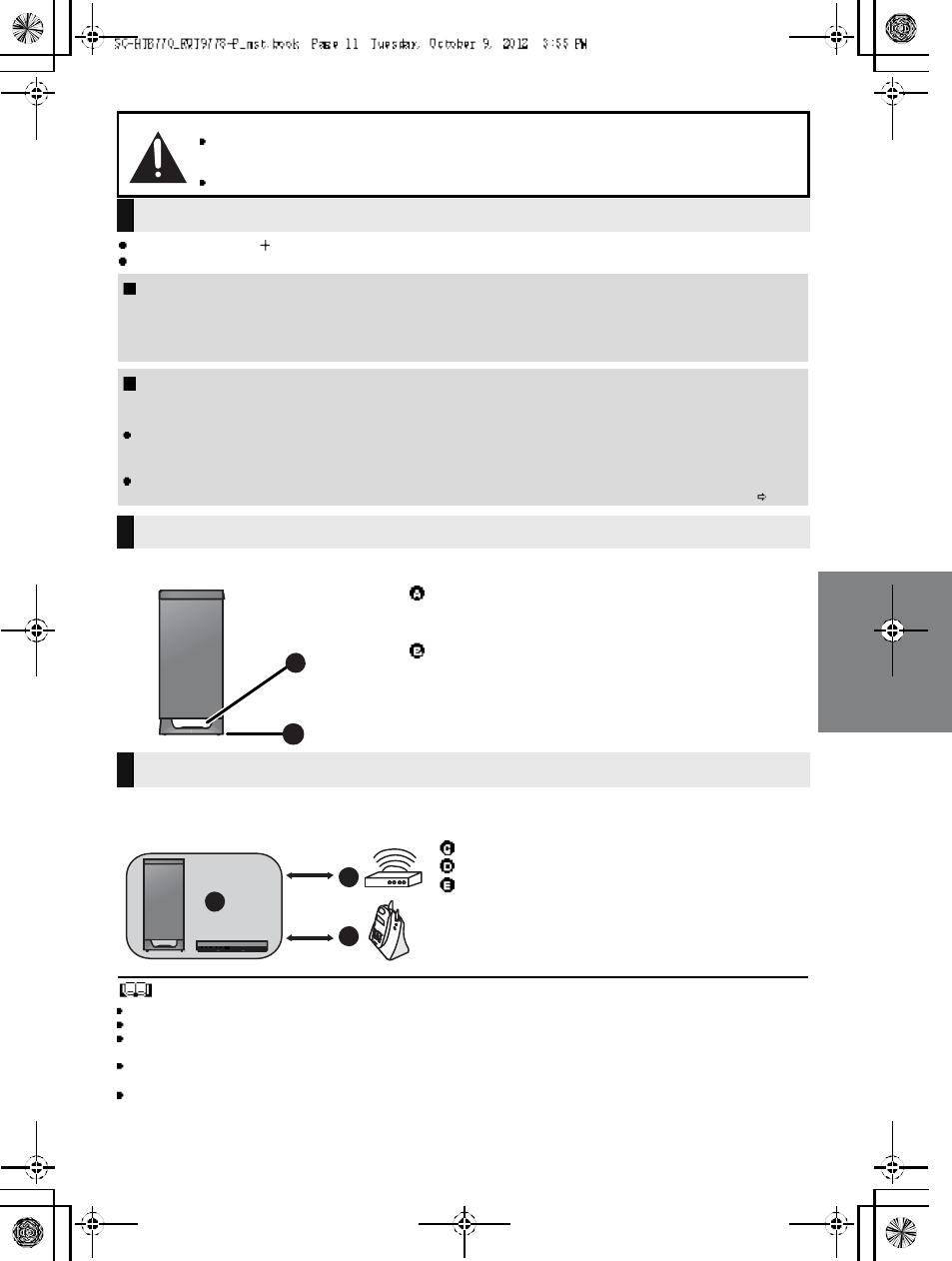
Caution
This unit is to be used only as indicated in these instructions. Failure to do so may lead to damage to the
amplifier and/or the speakers, and may result in the risk of fire. Consult a qualified service person if damage
has occurred or if you experience a sudden change in performance.
Do not attem pt to attach these speakers to a wall using methods other than those described in this manual.
The speaker system
When attaching the speakers to a wall
The wall or pillar on which the speakers are to be attached should be capable of supporting 33 kg (72.8 lbs) per screw.
Consultation with a qualified installation specialist is recommended when attaching the speakers to a wall. Improper attachment
may result in damage to the wall and speakers, and personal injury.
When placing the speakers in front of the TV
The speakers may block or interfere with the TVs various sensors (C.A.T.S. (Contrast Automatic Tracking System) sensor,
remote control sensor, etc.) and the 3D Eyewear transmitters on a 3D compatible TV.
If the stands are being used
Change the height of the stands and/or move the speakers further away from the TV. If the TV still does not function correctly,
try removing the stands.
If the stands are not used
Move the speakers further away from the TV. If the TV still does not function properly, try placing them beside the TV ( 10).
The active subwoofer
Do not hold the active subwoofer from this
opening .
The parts inside may get damaged.
Always hold the bottom of the active subwoofer when
moving it.
Wireless interference
Main unit/active subwoofer
Wireless LAN: approx. 2 m (6 1/2ft)
Cordless phone and other electronic devices:
approx. 2 m (6 1
/2ft)
12 R QT977 8
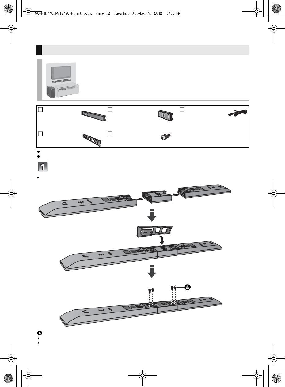
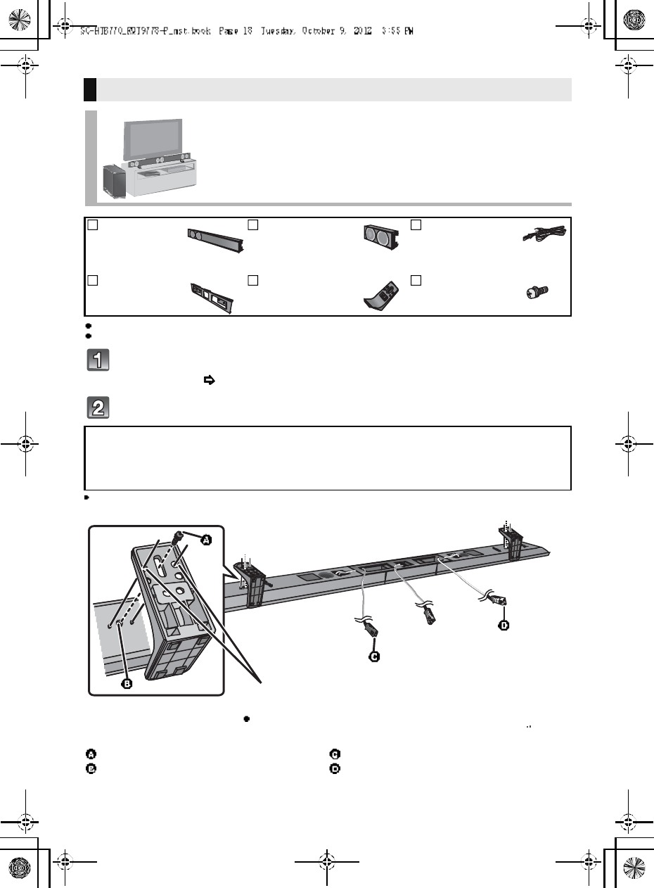
Step 2 Assembling the speakers
For a safety measure to prevent the speakers from falling, refer to page 22.
To prevent damage or scratches, lay down a soft cloth and perform the assembly on it.
Assemble the speakers.
Th e two front speakers are interchangeable.
When attaching the speakers to a wall
Place the speakers horizontally
2Fr ont
speakers
1 Center speaker 3 Speaker cables
WHITE: Left
RED: Right
GREEN: Center
1Metal bracket 4 Screws
Screw (supplied)
Be sure to insert the screws following the order as indicated in the illustration.
Keep the screws out of reach of children to prevent swallowing.
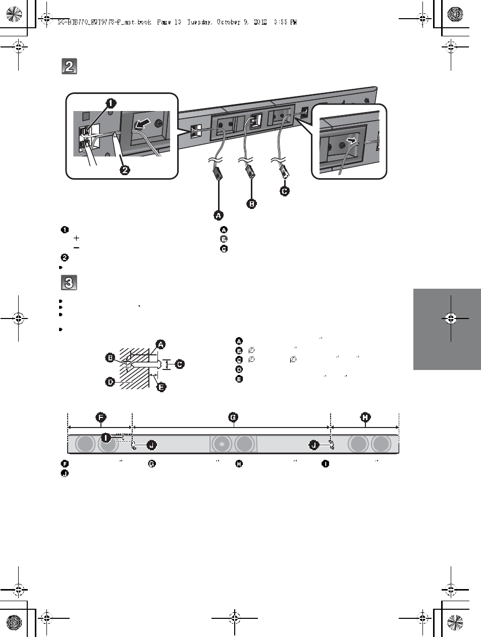
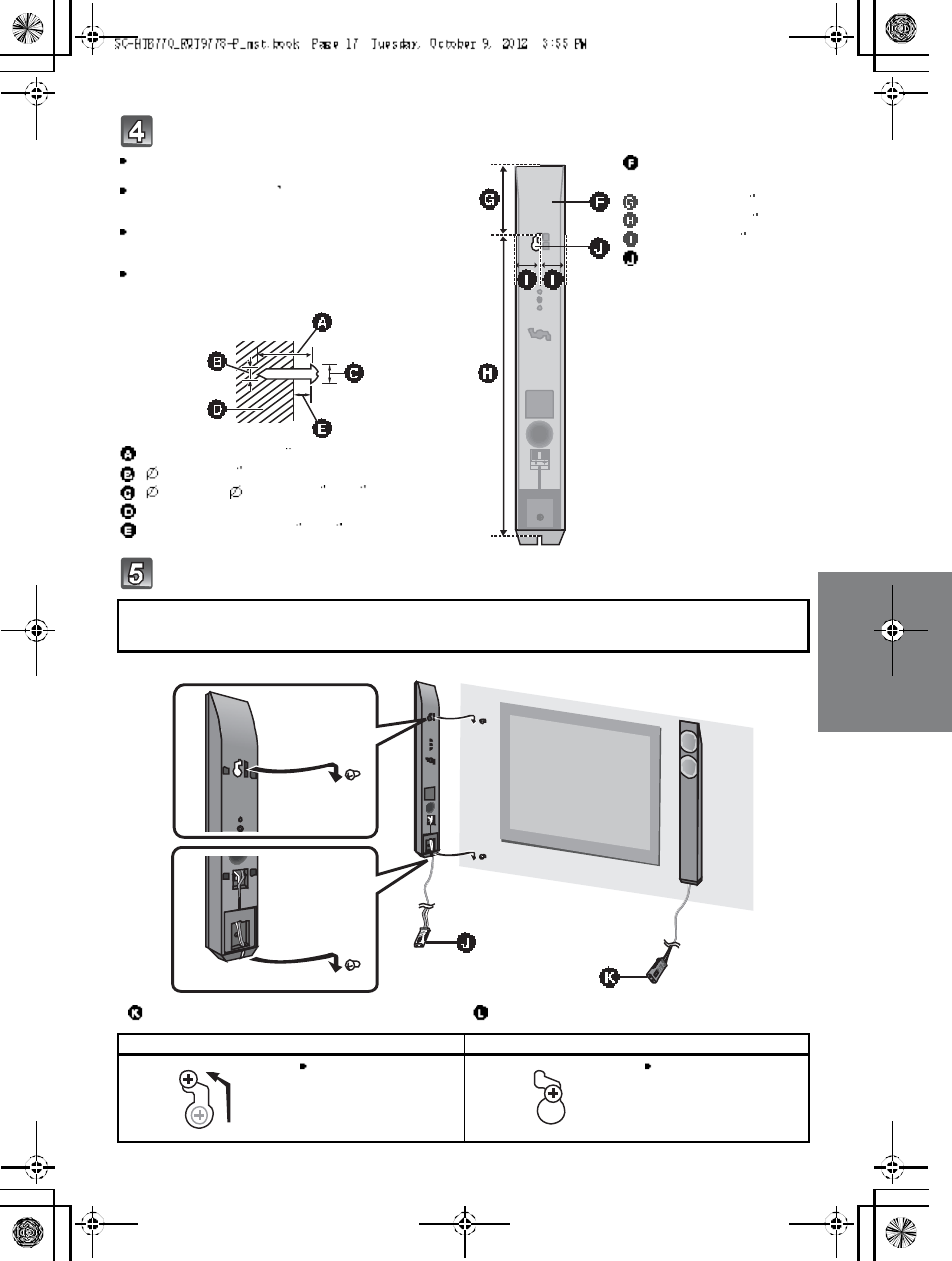
R QT977 8 13
Connect the speaker cables.
Insert the wire fully, taking care not to insert beyond the wire insulation.
Dr ive a screw into the wall.
Use the measurem ents indicated below to identify the screwing positions on the wall.
Leave at least 20 mm (25
/32 ) of space above and on each side of the speaker to allow enough space for fitting the speaker.
The position on the wall where the screw is to be attached, as well as the screw, should be capable of supporting over 33 kg
( 7 2. 8 l bs ).
Keep the screws out of reach of children to prevent swallowing.
Insert the wire fully.
: White
: Blue line
Press into the groove.
Right speaker connector
Center speaker connector
Left speaker connector
At least 30 mm (1 3/16 )
4.0 mm (5/32 )
7.0 mm to 9.4 mm (9/32 to 3/8)
Wall or pillar
5.5 mm to 6.5 mm (7/32 to 1/4)
248 mm (9 3
/4)745 mm (29 11
/32 )238 mm (9 3
/8)20 mm (25 /32 )
Wall mounting hole
Push
R ed
White
Green
Front view (semi-transparent image)
14 R QT977 8
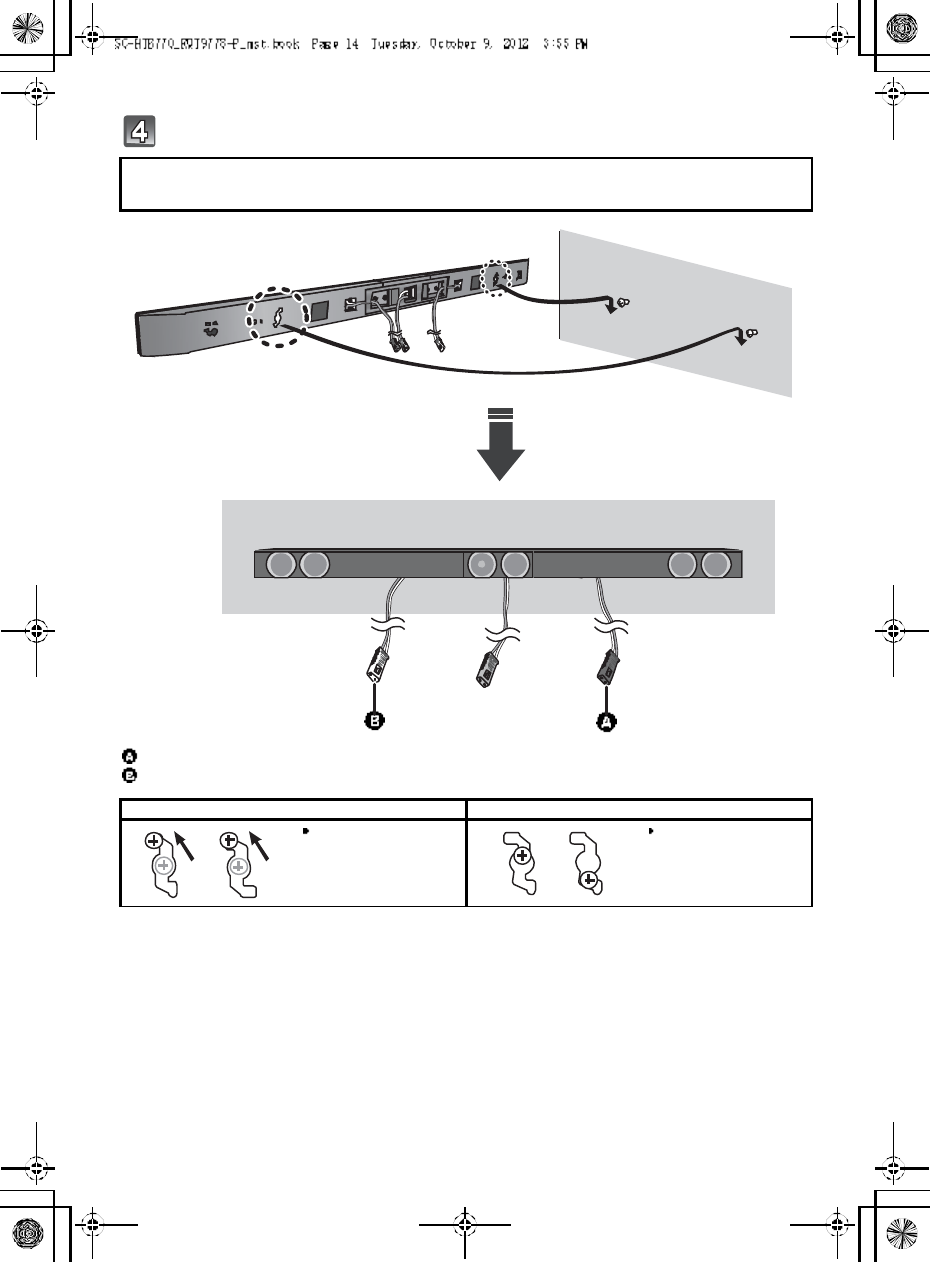
Fit the speaker securely onto the screw(s).
R ed co nn ect or: The speaker attached to the red connector cable is to be place on the right side
White conn ector: The speaker attached to the white connector cable is to be place on the left side
Right speaker connector
Left speaker connector
DO DO NOT
Move the speaker so
that the screw is i n this
position.
In this position, the
speaker will likely fall if
moved to the left or
right.
R ed
White
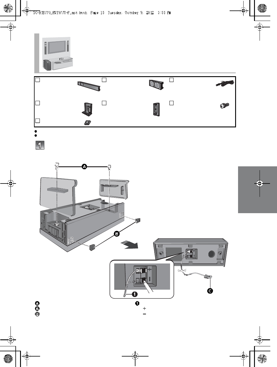
R QT977 8 15
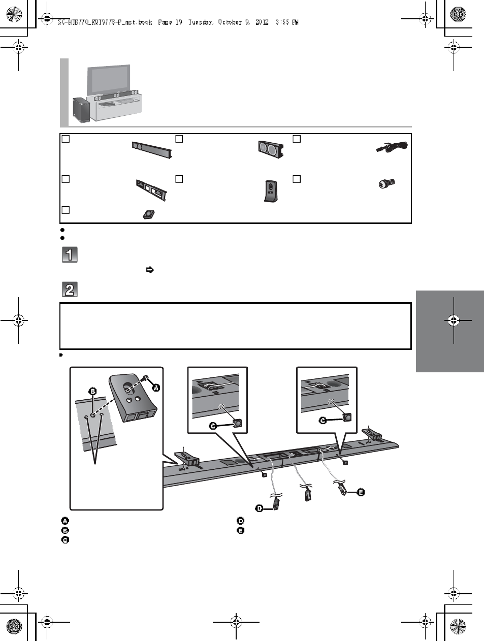
For a safety measure to prevent the speakers from falling, refer to page 22.
To prevent damage or scratches, lay down a soft cloth and perform the assembly on it.
Attach the side caps and speaker feet to the center speaker and connect
the speaker cable.
Place the front speakers vertically
2Fro nt
speakers
1 Center speaker 3 Speaker cables
WHITE: Left
RED: Right
GREEN: Center
2Stand necks 2 Side caps 4 Scr ew s
2 Speaker feet
Screw (supplied)
Speaker foot (supplied)
Center speaker connector
Insert the wire fully.
: White
: Blue line
Push
Green
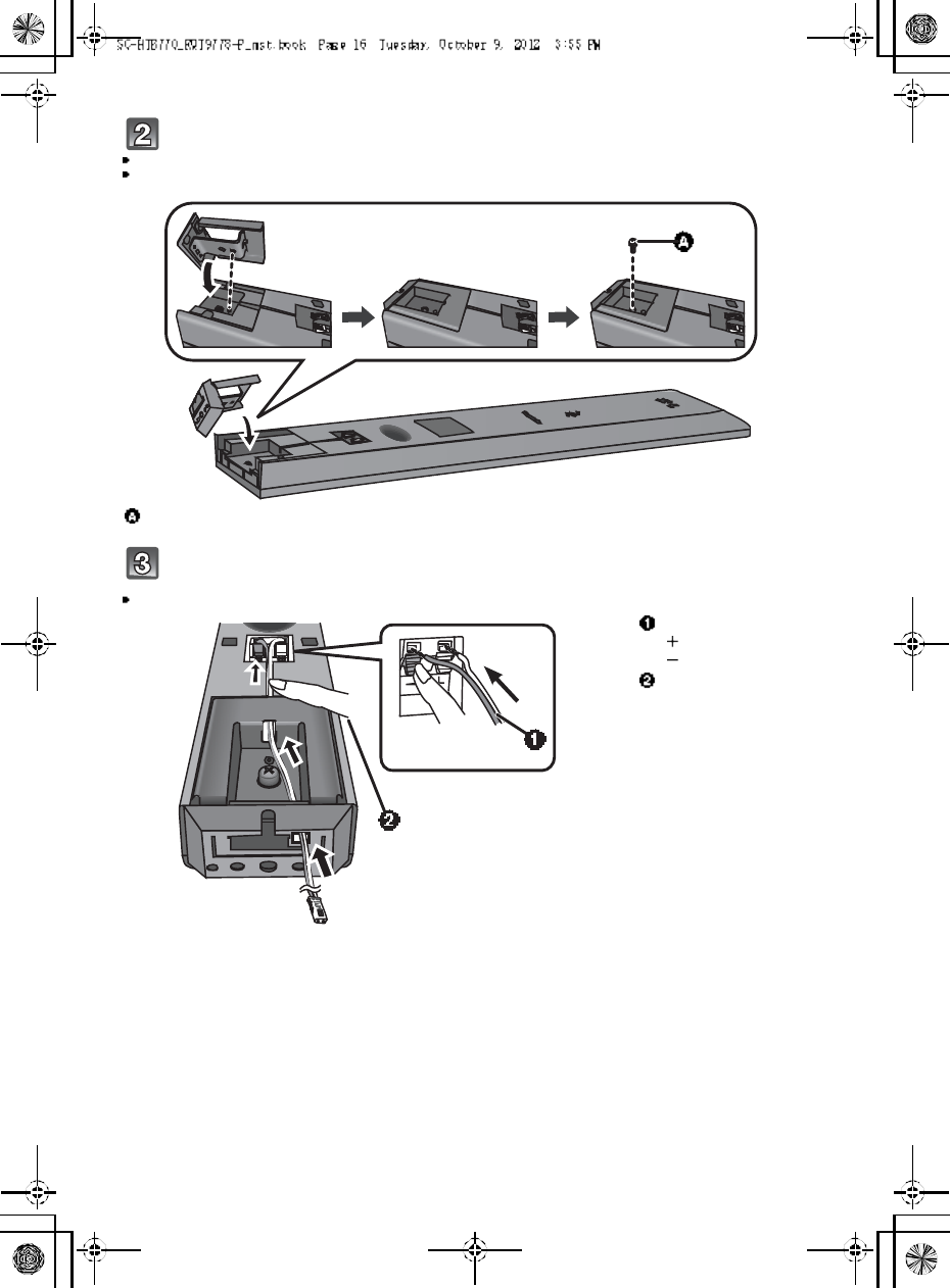
16 R QT977 8
Attach the stand neck.
Th e two front speakers are interchangeable.
Keep the screws out of reach of children to prevent swallowing.
Connect the speaker cables.
Insert the wire fully, taking care not to insert beyond the wire insulation.
Screw (supplied)
Insert the wire fully.
: White
: Blue line
Press into the groove.
Push
R QT977 8 17
Dr ive a screw into the wall.
Fit the front speaker(s) securely onto the screw(s).
Use the measurements indicated below to identify the
screwing positions on the wall.
Leave at least 20 mm (25/32 ) of space above and on each
sid e of the front speaker to allow enough space for fitting
the front speaker.
The position in the wall where the screw is to be attached
as well as the screw should be capable of supporting over
33kg (72.8 lbs).
Keep the screws out of reach of children to prevent
swallowing.
At least 30 mm (1 3/16 )
4.0 mm (5/32 )
7.0 mm to 9.4 mm (9/32 to 3/8)
Wall or pillar
5.5 mm to 6.5 mm (7/32 to 1/4)
Front speaker
(Rear view)
100 mm (3 15
/16 )
436 mm (17 5/32 )
34 mm (1 11
/32 )
Wall mounting hole
R ed co nn ect or: The speaker attached to the red connector cable is to be place on the right side.
White conn ector: The speaker attached to the white connector cable is to be place on the left side.
Left speaker connector Right speaker connector
DO DO NOT
Move the front sp eaker
so that the screw is in
this position.
In this position, the front
speaker will likely fall if
moved to the left or
right.
R ed
White
18 R QT977 8
For a safety measure to prevent the speakers from falling, refer to page 22.
To prevent damage or scratches, lay down a soft cloth and perform the assembly on it.
Assemble the speakers following steps 1 and 2 of Place the speakers
horizontally ( 12).
Attach the leg stands.
Keep the screws out of reach of children to prevent swallowing.
When placing the speakers on a table
Place the speakers using the leg stands
2Fr ont
speakers
1 Center speaker 3 Speaker cables
WHITE: Left
RED: Right
GREEN: Center
1Metal bracket 2Leg stands 6 Scr ew s
R ed co nn ect or: With the speaker facing down, the speaker attached to thered connector cable is to
be place on the left side.
White conn ector: With the speaker facing down, the speaker attached to the white connector cable is
to be place on the right side.
Screw (supplied)
Screw hole
Right speaker connector
Left speaker connector
Align the higher or lower holes with the projecting parts on the
speaker.
By changing the position that the stand is attached to the
projecting parts, the height can be adjusted by 10 mm (13
/32 ).
R ed
White
R QT977 8 19
For a safety measure to prevent the speakers from falling, refer to page 22.
To prevent damage or scratches, lay down a soft cloth and perform the assembly on it.
Assemble the speakers following steps 1 and 2 of Place the speakers
horizontally ( 12).
Attach the support legs and speaker feet.
Keep the screws and the speaker feet out of reach of children to prevent swallowing.
Place the speakers using the support legs and
speaker feet
2Fro nt
speakers
1 Center speaker 3 Speaker cables
WHITE: Left
RED: Right
GREEN: Center
1Metal bracket 2 Support legs 6 Scr ew s
2 Speaker feet
R ed co nn ect or: With the speaker facing down, the speaker attached to the red connector cable is to
be place on the left side.
White conn ector: With the speaker facing down, the speaker attached to the white connector cable is
to be place on the right side.
Screw (supplied)
Screw hole
Speaker foot (supplied)
Right speaker connector
Left speaker connector
Align the projecting
parts on the speaker
with support leg.
R ed
White
20 R QT977 8
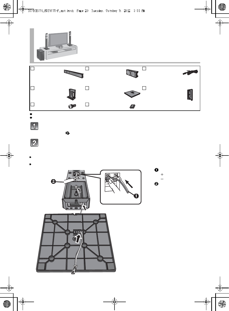
For a safety measure to prevent the speakers from falling, refer to page 22.
To prevent damage or scratches, lay down a soft cloth and perform the assembly on it.
Assemble the speakers following step 1 and 2 of Place the speakers
vertically ( 15).
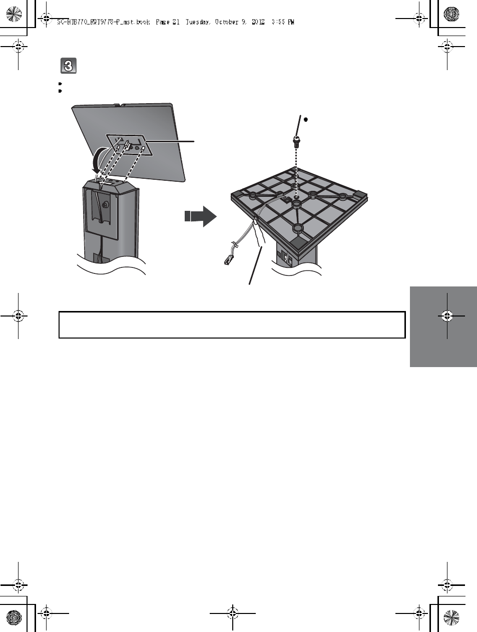
Insert the speaker cable through the speaker base and connect the
speaker cables.
Be sure to insert the speaker cable through the threading hole as indicated in the illustration. (If the speaker cable is twisted, it
might not fit through the opening. Straighten the speaker cable before inserting.)
Insert the wire fully, taking care not to insert beyond the wire insulation.
Place the front speakers using the speaker
bases
2Fr ont
speakers
1 Center speaker 3 Speaker cables
WHITE: Left
RED: Right
GREEN: Center
2Stand necks 2Speaker bases 2 Side caps
6 Scr ew s 2 Speaker feet
Insert the wire fully.
: White
: Blue line
Press into the groove.
Push
R QT977 8 21
Attach the speaker base to the front speaker.
Th e two front speakers are interchangeable.
Keep the screws out of reach of children to prevent swallowing.
R ed co nn ect or: The speaker attached to the red connector cable is to be place on the right side.
White conn ector: The speaker attached to the white connector cable is to be place on the left side.
Align the projecting
parts with the holes
on the speaker.
Press into the groove.
Screw (supplied)
Tighten securely.
22 R QT977 8
To prevent the speakers from falling, it is recommended, as an additional
protection measure, to attach the speakers to the wall or table with a fall
prevention cord (hereafter cord).
Consultation with a qualified installation specialist concerning the appropriate procedure when attaching to a concrete wall or a
surface that may not have strong enough support is recommended ( 13, 17). Improper attachment may result in damage to
the wall and speakers, and personal injury.
Use a cord that is capable of supporting over 10 kg (22.05 lbs) (with a diameter of about 1.5 mm (1/16 )).
The safety holder is to minimize the possibility of dam age and harm, but it does not guarantee this effect.
Keep the screws out of reach of children to prevent swallowing.
Make sure that the slack of the cord is minimal.
Additional speaker fall prevention measures
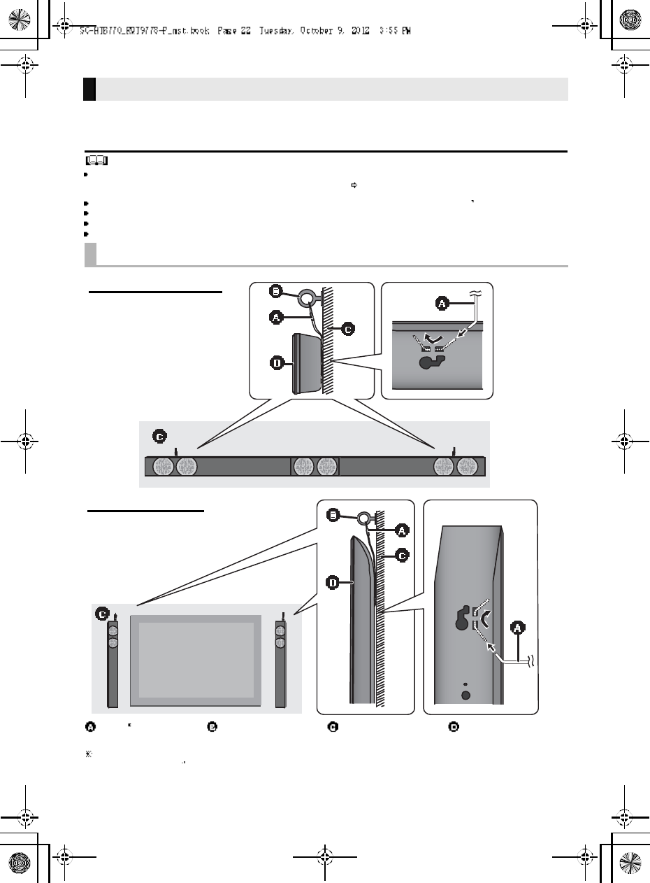
When attaching the speakers to a wall
Cord Screw eye Wall Wall-mounted
speakers
If the cord cannot be threaded through the holes, try bending the cord in 2 locations,
about 10 mm (13
/32 ) apart from the tip, at an angle of 45o (as illustrated above).
Horizontal placement
Vertical placement
R QT977 8 23
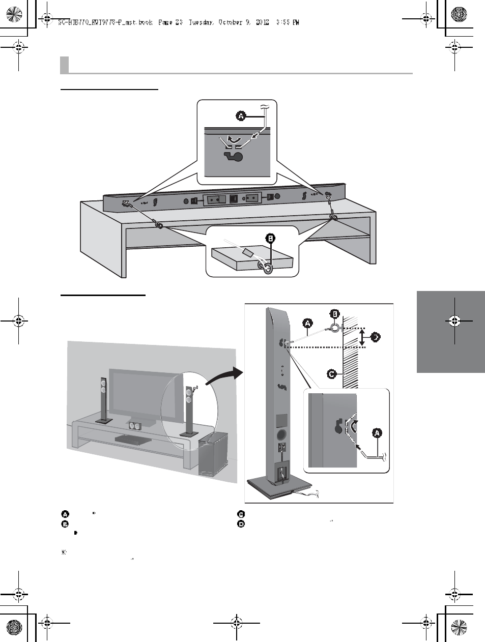
When placing the speakers on a table
Horizontal placement
Vertical placement
Cord
Screw eye
Depending on the placement of the speakers, the
screwing position of the screw eye may differ.
Wall
Approx. 150 mm (5 29 /32 )
If the cord cannot be threaded through the holes, try bending the cord in 2 locations,
about 10 mm (13 /32 ) apart from the tip, at an angle of 45o (as illustrated above).
24 R QT977 8
Step 3 Connections
Turn off all equipment before connection and read the appropriate owners manual.
Do not connect the AC power supply cord until all other connections are complete.
HDMI
The HDMI connection supports VIERA Link HDAVI Control ( 30) when used with a compatible Panasonic TV.
Use the High Speed HDMI Cables. It is recommended that you use Panasonics HDMI cable.
Recommended part number (High Speed HDMI cable):
RP -CDHS15 (1.5 m/4.9 ft), RP -CDHS 30 (3.0 m/9.8 ft), RP-CDHS 50 (5.0 m/16.4 ft), et c.
Non-HDMI-compliant cables cannot be utilized.
Verify if the TVs HDMI terminal is labeled HDMI (ARC).
What is ARC?
ARC is an abbreviation of Audio Return Channel, also known as H DMI ARC. It refers to one of the HDMI functions. When you
connect the main unit to the terminal labeled HDMI (ARC)on the TV, the optical digital audio cable that is usually required in
order to listen to sound from a TV is no longer required, and TV pictures and sound can be enjoyed with a single HDMI cable.
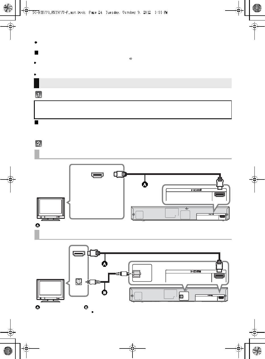
Make the connection.
Connection with the TV
Connection differs depending on the label printed next to the HDMI terminal.
Labeled HDMI (ARC): Connection [A]
Not Labeled HDMI (ARC): Connection [B]
[A] Labeled HDMI (ARC)
HDMI cable
[B] Not labeled HDMI (ARC)
HDMI cable Optical digital audio cable
When you use the optical digital audio cable, insert the tip correctly into the terminal.
A C IN
TV (A RC)
AV OUT
DIGITAL
AUD IO
IN
S P E AKE RS / HAU T -P ARL EUR S
HDMI IN (ARC)
TV (A R C)
AV OUT
Be sure to connect to
the TVs ARC
compatible terminal.
(Refer to the operating
instructions for the TV.)
TV
A C IN
TV (A RC)
AV OUT
DIGITAL
AUD IO
IN
TV
( OPT1)
S P E AKE RS / HAU T -P ARL EUR S
HDM I IN
OPTICAL
OUT
TV (A R C)
AV OUT
DIGITAL
AUDIO
IN
TV
(OPT1)
TV
R QT977 8 25
You can direct the audio signal from the connected Blu-ray DiscTM player, DVD player, Set Top Box, etc.
to this unit.
Preparation
Connect the main unit to the TV ( 24).
HDMI standby pass-through
Even if the main unit is in standby mode, the audio and/or video signal from the device connected to the BD/DVD, AUX1 or AUX2
terminal will be sent to the TV connected to the HDMI OUT terminal (the sound will not be output from this unit). When devices
a re c on n ec te d to all BD/DVD , AUX1 and AUX2 terminals, audio and/or video signal of the device whose input is lastly selected is
output.
3D compatibility
Compatible with FULL HD 3D TV and Blu-ray DiscTM player.
The main unit can through pass the 3D video signal from a 3D compatible Blu-ray DiscTM pla yer to a FU LL HD 3D TV.
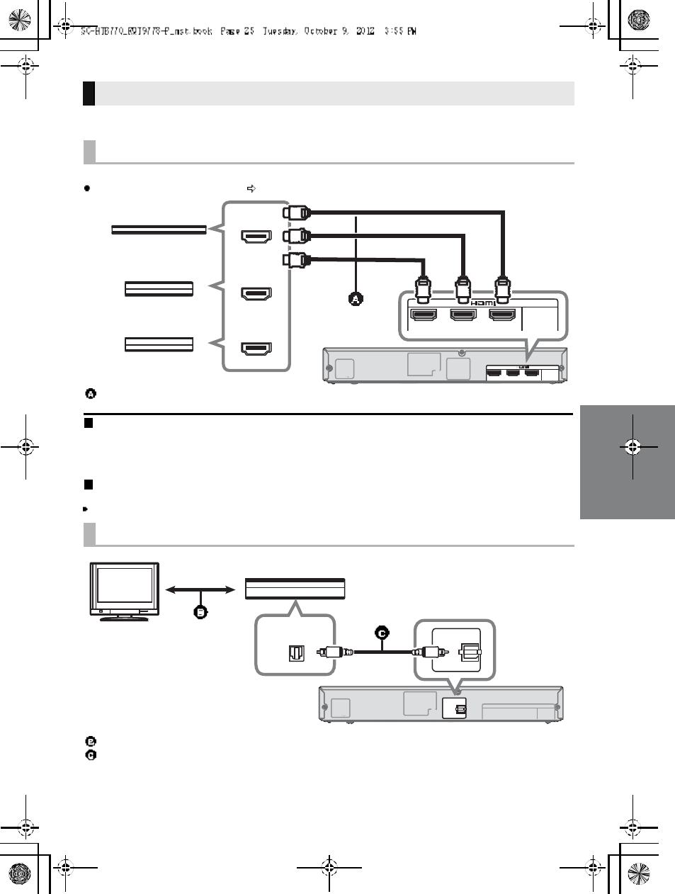
Connection with other devices
When the device has an HDMI terminal
HDMI cable
When the device has an optical digital audio output terminal
Refer to the operating instructions of the respective devices for the optimal connection
Optical digital audio cable
A C IN AV IN BD/ D VDBD/ D VDAU X1 ( HDMI1)( HDMI 2)
AU X2
( HDMI 3)
DIGITAL
AUD IO
IN
S P E AKE RS / HAU T -P ARL EUR S
AV IN
BD/DVDBD/DVDAUX1 (HDMI1)(HDMI2)
AUX2
(HDMI3)
HDM I OUT
HDM I OUT
HDM I OUT
e.g., Set top box
e.g., Blu-ray DiscTM player
e.g., Video game console
A C IN
DIGITAL
AUD IO
IN
AU X3
( OPT2)
S P E AKE RS / HAU T -P ARL EUR S
DIGITAL
AUDIO
IN
AUX3
(OPT2)
OPTICAL OUT
e.g., Set top box
TV
26 R QT977 8
Match the connector shape and connect to the terminals of the same color.
Connect only after all other connections are complete.
This unit consumes a small amount of AC power ( 35) even when it is turned off. In the interest of
power conservation, if you will not be using this unit for a long time, unplug it from the household AC
outlet.
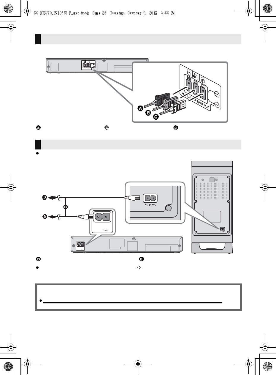
Speaker cable connection
RED
Right speaker connector
GREEN
Center speaker connector
WHITE
Left speaker connector
AC power supply cord connection
AC power supp ly cord To a household AC outlet
Saving energy
The main unit is designed to conserve its power consumption and save energy.
The main unit will automatically switch to standby mode when
no signal is input and no operation is performed for approx. 30 minutes.
R QT977 8 27
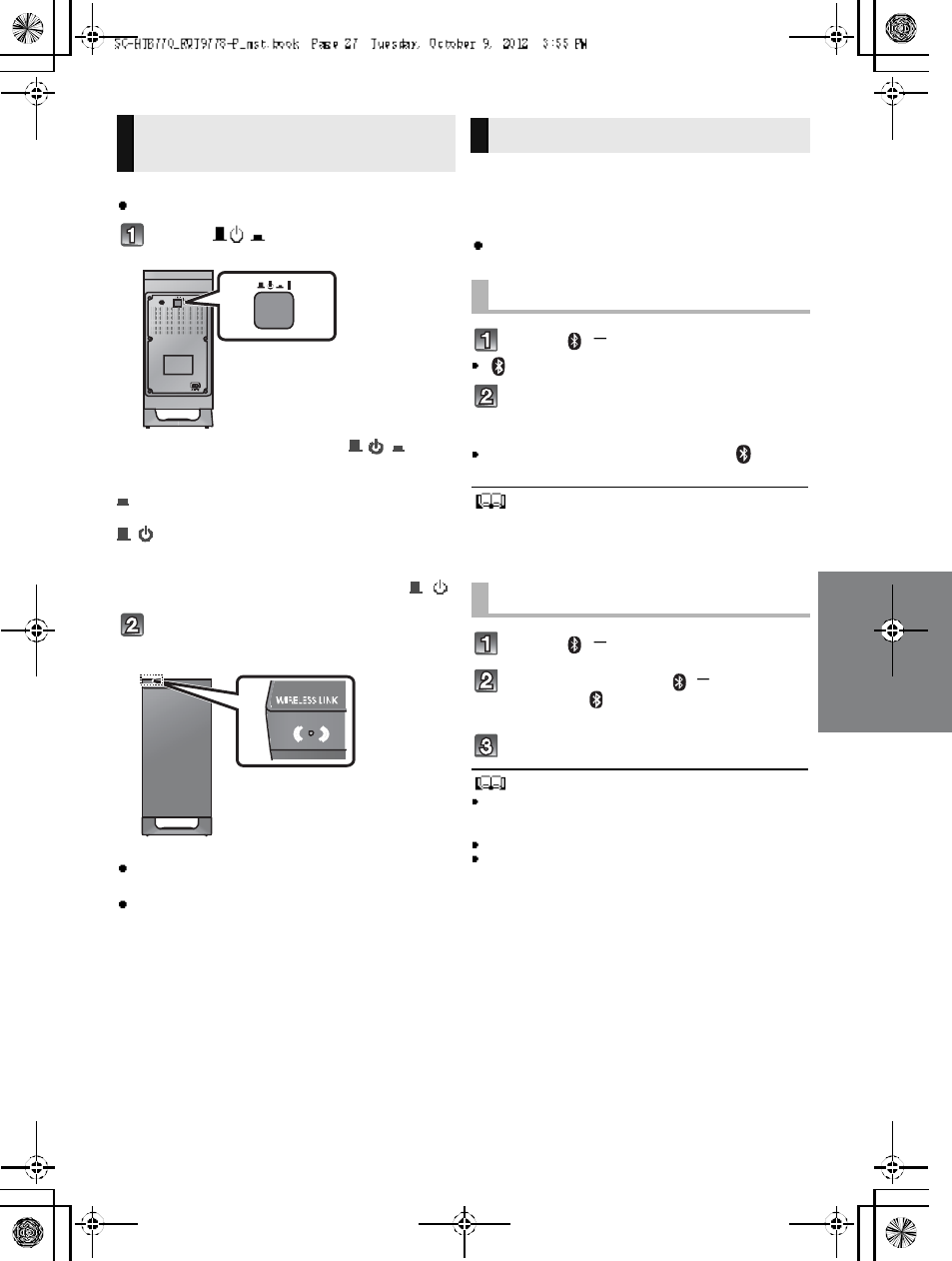
Preparation
Turn on the main unit.
Press [ I].
Active subwoo fer on/off bu tton [ , I]
Use this button to turn the active subwoofer on and
o f f.
I:
The active subwoofer is on
:
The active subwoofer is off
The active subwoofer will still consume a small
amount of power even when it is turned off ( , )
Check that the wireless link is
activated.
WIRELESS LINK indicator lights
Red:
The wireless link is not activated.
Green:
The wireless link is activated.
By using the Bluetooth® connection, you can listen
to the sound from the Bluetooth® audio device
from this unit wirelessly
Preparation
Turn on the Bluetooth® feature of the device and
place the device near this unit.
Press [ , PAIRING].
indicator will blink quickly.
Select SC-HTB770 from the
Bluetooth® devices Bluetooth®
menu.
O nc e t h e B l u et oo th ® device is connected, the indicator
stops flashing and lights up.
Refer to the operating instructions of the Bluetooth® device for
further instruction on how to connect a Bluetooth
® device.
If prompted for the passkey on the Bluetooth
® device, enter
0000.
Press [ , PAIRING].
Press and hold the [ , PAIRING]
until the indicator flashes
qui ckly.
Repeat step 2 of Pairing a device.
You c an regist er up to 8dev ice s with this u nit . If a 9th device
is paired, the device that has not been used for the longest
time will be replaced.
This unit can only be connected to one device at a time.
To change the sound quality, refer to Bluetooth
®
communication mode on page 31.
Active subwoofer wireless
connection Bluetooth® connection
Pairing a device
Pairing additional devices
28 R QT977 8
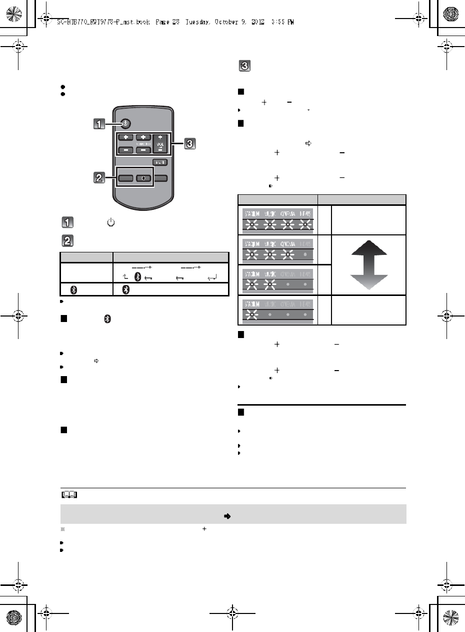
Using this unit
Preparation
Turn on the active subwoofer.
Turn on the TV and/or connected device.
Press [ ] to tu rn on the main unit.
Sel ect the sou rce.
This remote control cannot be used to control the operations
of the connected devices.
When is selected as the source
On the Bluetooth® device:
Select this unit as the output source of the Bluetooth®
device and start the playback.
Make sure that the Bluetooth®
device is already paired with
this unit. ( 2 7)
Playback may pause when a different source is selected.
When BD/DVD , AUX1 or AUX2
is selected as the source
On the connected device:
Select the TVs input for this unit and start the playb ack on
the connected device.
When AUX3 is selected as the
source
On the connected device:
Select the TVs input for the device connected to AUX3
terminal and start the playback on the connected device.
Adjust the volume and sound effect
level.
To adjust the volume of this unit
Press [ VOL ].
Volum e range: 1 to 100
To adj ust the dial og effect level
This setting will change the level of the Clear-
mode dialog effect. ( 29)
1 Press [ DIALOG LEVEL ] to display the
current level.
2 While the level is displayed:
Press [ DIALOG LEVEL ] to adjust the
level.
To adjust the subwoofer level
1 Press [ SUBWOOFER ] to display the
current level.
2 While the level is displayed:
Press [ SUBWOOFER ] to adjust the
level.
The level indication pattern is the same as dialog effect
level.
To mute the sound
Press [MUTE].
While muting, the sound mode indicators blink
simultaneously.
To cancel, press the button again or adjust the volume.
Muting is canceled if the main unit is turned off.
The sound mode indicators b lin k f rom left to rig ht ( ) or from right t o left ( ) wh ile adju sting .
The indicators will not blink when it has reached the maximum or minimum.
If there is sound coming out of the TVs speakers, reduce the volume of the TV to its minimum.
If the main unit is turned off with the volume setting in the greater half (above 50), the main unit will automatically lower the
volume to the middle (50) when the main unit is turned on (Volume limitation).
To turn this function off, refer to page 33.
Press To select
[IN PUT
SELECTOR]
TVBD/DVDAUX1
AUX3 AUX2
[] (Bluetooth®)
Indication Effect level
4Highest
3
2
1Lowest
If the main unit does not operate as expected or sound is unusual, return the settings to the
factory preset and operate the system again. ( 33)
R QT977 8 29
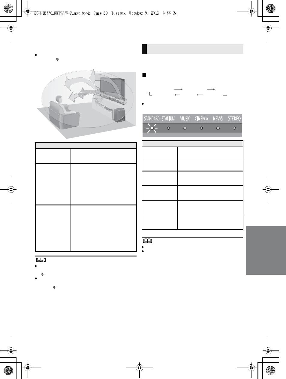
3D sound
This unit provides a feeling that the sound and the image
are as one.
To change the applied effect, refer to Audio output
modes. ( right)
To turn off Dolby Virtual Speaker and the 3D surround
effects, select STEREO as the audio output mode.
(right)
To turn off the 3D surround and the Clear-mode dialog
effects, refer to Only using the Dolby Virtual Speaker
e ffect . ( 3 2)
By changing the a udio output mode, i t is possible to enjoy
the sou nd that is sui table to the TV program or image from
the connected device.
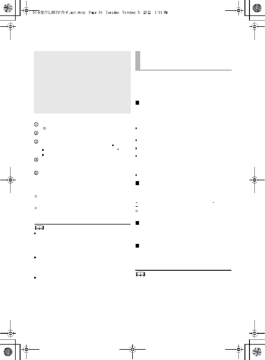
To select the sound mode
Press [SOUND].
STANDARDSTADIUMMU SIC
STEREO NEWS CINEMA
The indicator for the selected sound mode lights.
E.g., STANDARD
The setting is maintained until it is changed again.
When using the optical digital audio cable, Dolby Virtual
Speaker and the 3D surround effect will be temporarily
canceled if the audio signals sampling frequency is greater
than 48 kHz.
3D sou nd
Dolby Virtual
Speaker
With this effect you can enjoy a
surround sound effect similar to
5.1ch.
3D surr ound
effect
Adding to the Dolby Virtual
Speaker effect, Panasonic h as
applied its own sou nd field
control ling technology to expand
the sound field fo rwards,
backwards, upwards, and
downwards, providing a sound
with depth and fo rce that better
matches 3D images.
Clear-mode
dialog
Sports commentary and dialogs
from TV dramas are heard as if the
sound is coming from the TV,
giving the feeling that the sound
and the image are one.
Also, the dialog will stand out from
the other sounds during n ormal
volume playback and when the
volume is lowered for night time
viewing.
e.g., Image of 3D sound field
Audio output modes
Sound m ode
STANDARD
(Factory preset)
Produces a sou nd best suited for
dramas and comedy shows.
STAD IUMProduces a highly realistic sound
for live broadcasts of sports.
MUSIC
Re-crea tes the sound of musical
instruments and songs with an
expansive sound.
CINEM A
Produces a powerful, three-
dimenti onal sound unique to
movies.
NEWS
Enhances the voices of news and
sports commentaries for clearer
hearing.
STEREO
You can play any source in stereo.
Dolby Virtu al Speaker and 3D
surround effects are turned off.
30 R QT977 8
Linked operations with the TV
(VIERA LinkTMHDAVI ControlTM)
Preparation
Confirm that the HDMI connection has be en made.
(24, 25)
Set th e HDAV I Control operations on the connecte d
equipment (e.g., TV).
For the o ptimal HDAVI Control operations change
the following settings on the connected TV 1.
Set the default speaker settings to this unit.2
Set the speaker selection settings to this unit.
Turn on all HDAVI Control compatible equipment
and select the TVs input for this unit s o t hat th e
HDAVI Control function works properly.
If a device is connected to the HDMI IN terminal, start
play to check that the picture is displayed on the TV
correctly.
When the connection or settin gs are changed,
repeat this procedure.
1 The availability and function of the settings may vary
depending on the TV. Refer to the operating instructions
for the TV for details.
2 If the TV ha s a d efault sp eak er s ettin g with in the V IE RA
Link setting items, choosing this unit as the default
speaker will automatically change the speaker selection to
this unit.
VIERA Link HDAVI Control, based on the control functions
provided by HDMI which is an industry standard known as
HDMI CEC (Consumer Electronics Control), is a unique
function that we have developed and added. As such, its
operation with other manufacturers equipment that
supports HDMI CEC cannot be guaranteed.
This unit supports HDAVI Control 5 function.
HDAVI Control 5 is the newest standard (current as of
November, 2011) for Panasonics HDAVI Control compatible
equipment. This standard is compatible with Panasonics
conventional HDAVI equipment.
Please refer to individual manuals for other manufacturers
equipment supporting VIER A Link function.
To make sure that the audio is output from this unit, turn
the main unit on by using the TVs remote co ntrol and
selecting home theater from the speaker menu of VIERA
Link menu. The availability and function of the settings
may va ry depending on the TV. Refer to the operating
instructions for the TV for details.
Speaker control
You can select whether audio output is from this unit or
the TV speakers by using the TV menu settings.
Home theater
This unit is active.
W h en this unit is in standby mode, changing the TV
speakers to this unit in the VIERA Link menu will
a ut om at ic all y tu rn this unit on and select TV as the source.
Yo u ca n cont r ol t he volume se t ting of this unit using the
volume or m ute button on the TV remote control.
If yo u turn off this unit, TV speakers will be automatically
activated.
Audio will automatically be output from this unit if the TV is
compatible to VIERA Link HDAVI Control 4 or later.
TV
TV speakers are active.
The volume of this unit is se t t o its minimum.
Automatic input switching
When the following operations are performed, this unit will
automa tically change the input to the corresponding
source.
When play starts on an HDMI connected device. 3
When the TV input or the TV channel is changed.
3 If th e sp eak er ou tp ut s et tin g on t he TV is se t to this unit,
the TV and this unit turn on automatically (Power on link).
Power off link
When the TV is turned off, the main unit also turns o ff
automatically. (This function does not work when
Bluetooth® is the source.)
Automatic lip-sync function
(for HDAVI Control 3 or later)
Delay between audio and video is automatically adjusted
by addi ng time- lag to the audio ou tput, enabling you to
enjoy smooth audio for the pictur e.
The delay information is automatically set if the TV is
compatible to VIERA Link HDAVI Control 3 or later and the
VIERA Link is set to on.
What is VIERA Link HDAVI
Control?
VIERA Link TM is a new name for EZ SyncTM.
VIERA Link HDAVI Control is a convenient
function that offers linked operations of this
unit, and a Panasonic TV (VIERA) under
HDAVI Control.
You can use this function by connecting the
equipment with an HDMI cable. See the
operating instructions for connected
equipment for operational details.
What you can do with
VIERA Link HDAVI
Control
R QT977 8 31
Advanced operations
To display the current au dio format,
Press and hold [SOUND] for more than
4 sec.
The current audio format is indicated for 5 sec.
The audio format status is also indicated for 5 sec if the
audio format on the selected source (TV, Blu-ray Disc/
DVD Player, etc.) is changed.
Change the dual audio from main to secondary.
This setting will only work if the audio outp ut settin g on
the connected TV or player, etc. is set to "Bitstream"
and dual audio is available in the audio source.
Press and h old [MUTE] for more than
4 sec.
While the setting is displayed, press
[MUTE] to change the setting.
The indicator for the selected setting blinks for 20 sec and
then exits the setting mode.
The setting is maintained until it is changed again.
The same setting is used for all digital audio sources.
With this function, you can prevent sudden loud sounds.
The output will be reduced automatically when the input
exceeds a certain level.
Press and hold [INPUT SELECTOR]
on remote controller for more than
4sec.
While the setting is displayed, press
[INPUT SELECTOR] to change the
setting.
The indicator for the selected setting blinks for 20 sec and
then exits the setting mode.
The setting changes each time [INPUT SELECTOR] is
pressed.
The setting is maintained until it is changed again.
Default se t ting of th is f unc tion is O FF.
You can select different modes to suit the type of
connections which emphasis on connectivity or high
quality audio.
Make su re that a Bluetoo th® device is already paired
with this unit. ( 27)
Disable the Bluetooth® connection of
the device.
indicator will blink slowly.
Press [LINK MODE, ] to display the
current mode.
While the mode is displayed, press
[LINK MODE, ] to select the mode.
The setting changes each time [LINK MODE, ] is
pressed.
The indicator for the selected setting blinks for 10 sec and
then exits the setting mode.
The setting is maintained until it is changed again.
Audio format indicator
STADIUM indicator blinks:
Dolby Digital is the audio format.
MUSIC indicator blinks:
DTS is the audio format.
CINEMA indicator blinks:
PCM or LPCM is the audio format.
Changing the dual audio
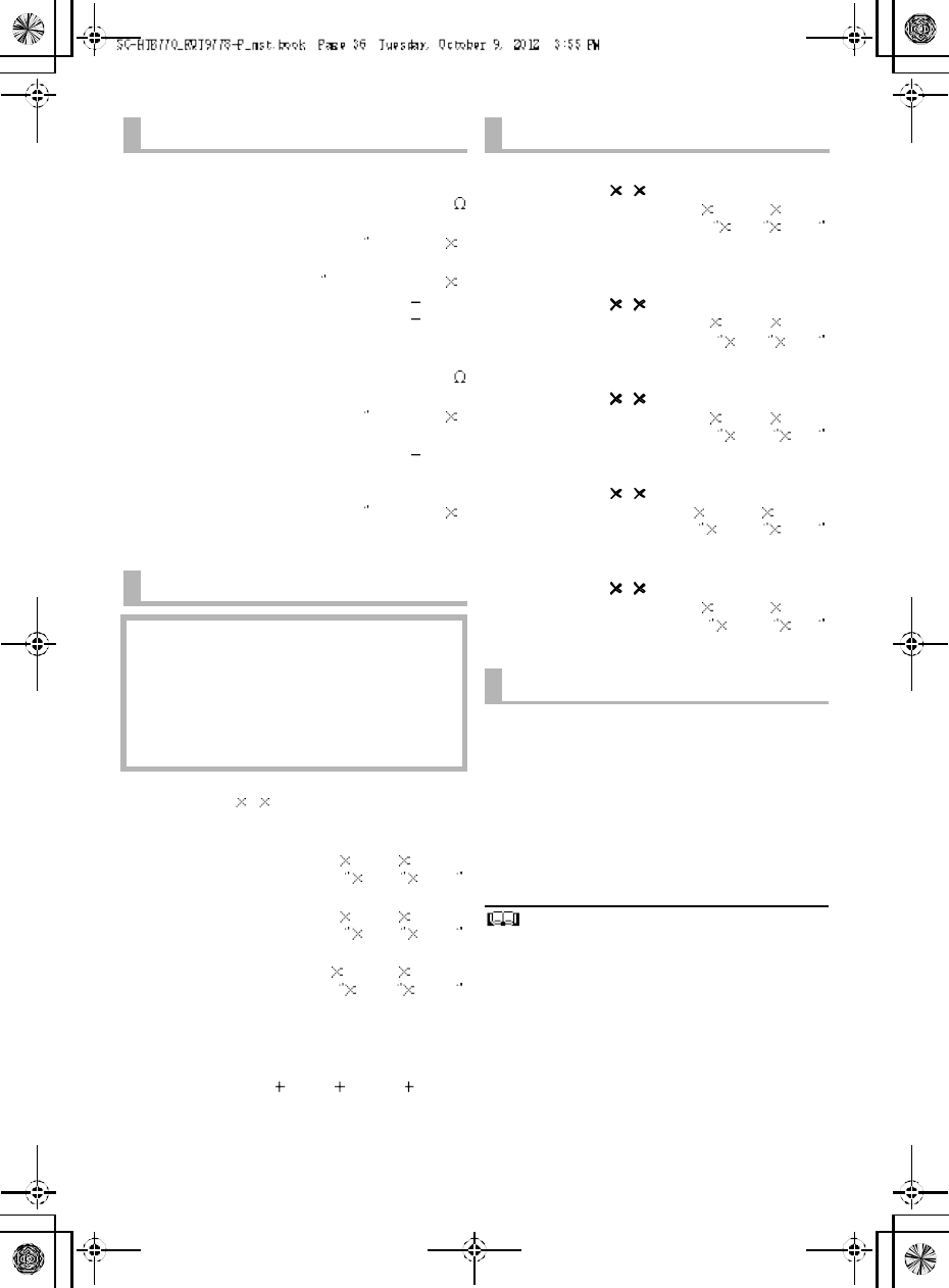
STANDARD indicator blinks ( ):
M a in (Factory preset)
STEREO indicator blinks ( ):
Secondary
(SAP: Secondary Audio Program)
, : Main and secondary
Auto gain control
STANDARD indicator blinks:
Auto gain control is on.
STEREO indicator blinks:
Auto gain control is off.
(Factory preset)
Bluetooth® communication
mode
STANDARD indicator blinks:
MODE1 (Factory preset)
Emphasis on connectivity
STEREO indicator blinks:
MODE2
Emphasis on audio quality
32 R QT977 8
Depending on your preferen ce, It is possible to turn off the
3D surround effect a nd the clear-mode dialog effect.
While pressing and holding [SOUND]
on the remote control, press and
hold [VOL ] on the main unit for
more than 4 sec.
Whi le th e setti ng is di spl ayed, press
[SOUND] to change the setting.
The setting changes each time [SOUND] is pressed.
The indicator for the selected setting blinks for 20 sec and
then exits the setting mode.
This setting will be reset to on when this unit is turned off.
When off is selected, the dialog effect level cannot be
adjusted.
You can turn off dimmer mode and keep the LED
indicators bright.
While pressing and holding [INPUT
SELECTOR] on the remote control, press
and hold [ VOL] on the main unit to turn
off Dimmer mode.
The indicator for the current condition will turn brighter.
The setting is maintained until it is changed again.
Default setting of this function is on.
To turn on dimmer mode, repeat the operation above.
After performancing the operation, the indicator for the
current condition will be dim.
Remote control code
When other Panasonic devices respond to this units
remote control, change the remote control code on the
main un it and the remote control.
Preparation
Turn off all other Panasonic products.
Turn on the main unit.
Change the remote control code to code 2:
1 Aim the remote control at this units remote
control sensor.
2 Press and hold [MUTE] and [ ] on the remote
control for more than 4 sec.
All the indicators will blink for 10 sec when the code of
this unit is changed.
The setting is maintained until it is changed again.
If this unit does not operate after changing the code, repeat
steps 1 and 2.
To change the remote control code to code 1, repeat the
steps above, but replace []with [INPUT SELECTOR].
To reduce the clear-mode dialog effect
When the dialog does not sound natural while the volume
is set low, it is p ossible to reduce the dialog enhancing
effect as follows:
While pressing and holding [SOUND] on the
remote control, press and hold [ VOL] on the
main unit for more than 2 sec.
All the indicators will blink once when the clear-mode dialog
effect is reduced.
Even if clear-mode dialog effect is reduced, dialog effect
level is still adjustable.
To reset th e setting, re turn to the f ac to ry p res et. ( 3 3)
Only using the Dolby
Virtual Speaker effect
STANDARD indicator blinks:
3D surround effect and clear-mode
dialog effect is on.
STEREO indicator blinks:
3D surround effect and clear-mode
dialog effect is off.
Dimmer mode
Others
R QT977 8 33
To turn off VIERA Link HDAVI
Control
When HDAVI Control compa tible equipment does not
work well with this unit, for example, it is possible to turn
off this function as fo llows:
When VIERA Link is turn ed off the ARC function is not
available. Be sure to connect the optical digital audio
cable. ( 24)
1 While pressing and holding [MUTE] on the
remote control, press and hold [ VOL] on the
main unit for more than 4 sec.
2 After the setting has changed, turn off all the
connected devices and then turn them on
again.
All the indicators will blink once when VIERA Link HDAVI
Control is turned off.
To re se t the se ttin g, re turn to t he f ac to ry preset. ( right)
To turn off the volume limitation
If a state of the lowe red volume disturbs you every time
this unit turns on, for example, it is possible to turn off this
function as follows:
While pressing and holding [MUTE] on the remote
control, press and hold [VOL ] on the main unit
for more than 2 sec.
All the indicators will blink once when the volum e limitation
is turned off.
To re se t the se ttin g, re turn to t he f ac to ry preset. ( right)
Troubleshooting
Before re questing service, make the following checks. If
you are in doubt about some of the check points, or if the
solutions indicated in the following guide do not solve the
problem, refer to Customer Services Directory (United
States and Puerto Rico) on page 38 if you re side in the
U.S.A. o r Puerto Rico, or refer to WARRANTY SERVICE
on page 39 if you reside in Canada.
No power.
Insert the AC power supply cord securely. ( 26)
After turning the main unit on, if the indicators blink a nd
the main unit immediately turns off, unplug the AC
power supply cord and consult you r dealer.
The remote control does not work properly.
The battery is depleted. Replace it with a new one.
(9)
It is possible that the insulation sheet has not been
removed. Remove the insulation sheet. ( 9)
It may be necessary to set the code of the remote
control again after changing the battery of the remote
control. ( 32)
Use the remote control within the correct operation
range. ( 9)
The TV indicator blinks.
Remove the AC power supply cord and consult yo ur
dealer. If there are any oth er indicators blinking, be sure
to inform your dealer about the blinking indicators.
The main unit is automatically switched to
standby mode.
The main unit wi ll automatically switch to standby mode
when no signal is input and no operation is performed for
approx. 30 minutes. ( 26)
The main unit is turned off when the TVs
speakers are selected in the speaker control.
This is a normal feature when using VIERA Link (HDAVI
Control 4 or later). Please read the operatin g instructions
for the TV for detail s about its power save fea ture. ( 30)
To return to the factory preset.
While the main unit is on, press [ /I] on the main
unit for more than 4 sec.
(All the indicators will blink twice when the main
unit is reset.)
If this unit does not operate as expected,
returning the settings to the factory preset
may solve the problem.
The remote control code will return to when
the main unit is returned to the factory preset.
To change the remote control code, refer to
page 32.
General operation

34 R QT977 8
This unit does not operate correctly.
If the HDMI cable is connected to the wrong terminal
(HDMI IN or HDMI OUT), this unit will not operate
correctly. Turn the main unit off, disconnect the AC power
supply cord and reconnect the HDMI cable(s). ( 24, 25)
VIERA Link related operations no longer
function properly.
Check the VIERA Link setting on the connected
devices.
Have you turned the VIERA Link settings off? ( 33)
When the HDMI connectio ns are changed , after a
power failure or afte r the AC power supply cord has
been removed, VIERA Link operations may not function
properly.
Turn on all the devices that are connected to the TV
with an HDMI cable and then turn the TV on.
Turn off the VIERA Link settings of the TV and turn it
on again. For details refer to the operating
instructions for the TV.
While this unit and the TV are connected with the
HDMI ca ble, turn on the TV and then remove the
main uni ts AC power supply cord and reconnect it
again.
The first few seconds of audio cannot be heard
wh en using the HDMI co nn ection.
This may occur during DVD-Video chapter playback.
Change the digital audio output setting on the connected
device from Bitstre am to PCM.
When operating an HDMI compatible device of
a different brand, the main unit reacts in an
unwanted manner.
HDAVI Control commands may use a different si gnal
depending on the brand of the device. In th is case, turn
VIERA Link off. ( 33)
Pairing cannot be done.
Check the Bluetooth® device condition.
The device cannot be connected.
The pairing of the device was unsuccessful. Try pairing
the device again.
The pairing of the device has been replaced . Pair the
device again. ( 27)
This unit might be connected to a different device.
Disconnect the other device and try pairing the device
again.
The device is connected but audio can not be
heard through this unit.
For some built-in Bluetooth® devices, you have to set the
audio output to SC-HTB770 manually. Read the
operating instructions for the device for detai ls.
Sound from the device is uneven.
The device is out of the 10 m (33 ft) communication
range. Brin g the device closer to the main unit.
Remove any obstacle between the main unit and the
device.
Switch off any wireless LAN device.
Select MODE1 fo r stable communication. ( 31)
No sound (or image).
Turn muting off. ( 28)
Check the connections to the other devices. ( 24, 25)
Make sure that the received audio signal is compatible
with this unit. ( 35)
Turn this unit off and then on again.
Ifthis unit is conne cted to the TV with only an HDMI
cable, make sure th at the TVs HDMI terminal is labeled
HDMI (ARC). If not, connect using the optical digital
audio cable. ( 24)
Ifthis unit is conne cted to a Panasonic TV and turned
on using the button on the main unit or the remote
control, sound might not be output from this unit. In this
case, turn the main unit on using the TVs remote
control. ( 30)
If the connections are correct, there might be a problem
with the cables. Redo the connections with different
cables.
Check the audio output settings on the connected
device.
If the BD/DVD indicator flashes and the re is no audio
output, try the following.
Turn the connected device off and then o n.
Turn off this unit, remove the HDMI cable, then
reconnect the HDMI cable and turn this unit back
on.
The dual audio can not be changed fro m main
to secondary.
If the audio received from the connected de vice is not
Dolby Dual Mono or the output setting is not Bitstream,
the setting cannot be changed from this unit. Change the
setting o n the connected device.
The volume is lowered when this unit is turned
on.
If the main unit is turne d off with the volume setting in the
greater half (above 50), the main unit will automatically
lower the volume to the middle (50) when the main unit is
turned o n. ( 33)
The dialog is too persistent or the dialog does
not sou nd natural.
This u nit has a function to make the dialog stand out when
the volume is low. ( 32)
HDMI
Bluetooth®
Sound
R QT977 8 35
There is no audio.
The power of the main unit turns off
automatically.
(When the main unit detects a problem, a safety measure
is activated and the main unit automatically switches to
standby mode.)
There is a problem with the amplifier.
Is the volu me extremely high?
If so, lower the volume.
Isthis unit placed in an extremely hot place ?
If so, move this unit to a cooler place and wait a few
moments and then try to turn it on again.
If the problem persists, con firm the TV indicator and
BD/DVD indicator blink, turn this unit off, remove the AC
power supply cord and consult your deal er. Please be
sure to remember the indicators that were blinking and
inform th e dealer.
No power.
Ensure the AC power supply cord of the active subwoofer
is connected properly.
After turning the subwoofer on, it immediately
tu rns off.
Unplug the AC power supply cord and consult your dealer.
No sound from the subwoofer.
Check that the a ctive su bwoofer is turned on.
Check that the wireless link indicator lights green.
(27)
The wireless link indicator lights red.
There is no link between this unit and the active
subwoofer.
Check that this unit is turned on.
Turn the active subwoofer off and then back on.
Alternatively, turn the active subwoofer off,
discon nect the AC powe r supply cord and then
reconnect it.
The active subwoofer an d the main unit may not be
paired corr ectly. Try the following op eration. (Wireless
pairing)
Turn on the main unit and active subwoofer.
Press [ID SET] on the rear of the active subwoofer.
(The WIRELESS LINK indicator will light red and
green alternately.)
While pressing and holding [INPUT SELECTOR] on
remote control, press an d hold [VOL ] on the main
unit for more than 4 sec. (The BD/DVD indicator will
blink and sound mode indicators light up in
sequence.)
When the wireless pairing is successful, BD/DVD
indicator will stop flashing and WIRELESS LINK
indicator lights green.
Turn the main unit off and on.
Consult your dealer if the problem persists.
Specifications
Active Subwoofer
AMPLIFIER SECTION
RMS ou tput power
10 % total harmonic distortion
Subwoofer ch
120 W per channel (100 Hz, 8 )
Fro nt ch (L, R ch)
60 W per channel (1 kHz, 6 )
Center ch (C ch)
60 W per channel (1 kHz, 6 )
Total RMS Dolby Digital mode power
300 W
FTC output pow er
1.0 % total harmonic distortion
Subwoofer ch
60Hzto120Hz40W(8 )
Fro nt ch (L, R ch)
120 Hz to 20 kHz 25 W (6 )
Center ch (C ch)
120 Hz to 20 kHz 25 W (6 )
Total FTC Dolby Digital m ode power
115 W
WIRELESS SECTION
Wireless module
Frequency Range 2.4 GHz band
Number of channels 3
TERMINAL SECTION
HDAVI Co ntro l
This unit supports HDAVI Control 5 function.
HDMI AV input (BD/DVD, AUX1) 2
Inp ut connector Type A (19 pin)
HDMI AV output (TV (ARC)) 1
Output con nector Type A (19 pin)
Digital audio input
Optical digital input (TV, AUX2) 2
Sampling frequency
32 kHz, 44.1 kHz, 48 kHz
88.2 kHz, 96 kHz (only LPCM)
Audio form at
LPCM, Dolby Digital, DTS
36 R QT977 8
1 Specifications are subject to change without notice.
2 Weight and dimensions are approximate.
3 Total harmonic distortion is measured by a digital spectrum
analyzer.
SPEAKER SECTION
Front speakers
2 way, 2 speaker system (Bass reflex type)
Speaker unit(s) Impedance 6
Woofer
6.5 cm (2 1/2) cone type 1
Tweeter
2.5 cm (1 ) semi-dome type 1
Frequency range 100 Hz to 30 kHz ( 16 dB)
150 Hz to 25 kHz ( 10 dB)
Center speaker
1 way, 1 speaker system
Speaker unit(s) Impedance 6
Full r ange
6.5 cm (2 1/2) cone type 1
Frequency range 100 Hz to 30 kHz ( 16 dB)
150 Hz to 25 kHz ( 10 dB)
Active subwoofer
1 way, 1 speaker system (Bass reflex type)
Woofer 16 cm (6 1/2) cone type 1
Frequency range 30 Hz to 180 Hz ( 16 dB)
35 Hz to 160 Hz ( 10 dB)
GENERAL
Pow er consump tion Main unit: 37 W
Active subwoofer: 20 W
In standby condition
Main unit (When the other connected devicesare
turned off)
Approx. 0.25 W
Active subwoofer: Approx. 0.2 W
Power sup ply AC 120 V, 60 Hz
Dimensions (W HD)
Main unit
Cabinet dim ension
310 mm 44 mm 195 mm
(12 7
/32 123 /32 711
/16 )
Maximum outer dimension
310 mm 45 mm 202 mm
(12 7
/32 125 /32 715
/16 )
Active subwoofer
180 mm 408 mm 306 mm
(7 3/32 16 1/16 12 1/16 )
Mass (Weight)
Main unit 1.1kg(2.4 lbs)
Active subwoofer 5.2kg(11.47 lbs)
Operating temperature range
0oC to 40 o
C ( 32 oF to 104 oF)
Op erating humidity range
20 % to 80 % RH (no condensation)
SPEAKER GENERA L
Horizontal placement using the stands
Dimensions (W HD)
956 mm 102 mm 74 mm
( 37 5/841/32 229
/32 )
Mass (Weight) 1.61 kg(3.7 lbs)
Horizontal placement using the speaker feet
and the support legs
Dimensions (W HD)
956 mm 78 mm 55 mm
(37 5/831
/16 25/32 )
Mass (Weight) 1.57 kg(3.5 lbs)
Horizontal placement (for wall mount)
Dimensions (W HD)
956 mm 75 mm 35 mm
(37 5/8215 /16 13/8)
Mass (Weight) 1.54 kg(3.5 lbs)
Vertical placement using the speaker bases
Dimensions (W HD)
148 mm 528 mm 145 mm
(5 13 /16 20 25 /32 523
/32 )
Mass (Weight) 0.88 kg(1.98 lbs)
Vertical placement (for wall mount)
Dimensions (W HD)
75 mm 478 mm 35 mm
(2 15 /16 18 13 /16 13/8)
Mass (Weight) 0.77 kg(1.76 lbs)
Bluetooth® SECTION
B lue to oth ® system specification
V3.0
Wireless equipment classification
Class 2 (2.5 mW)
Supported profiles A2DP, AVRCP
Fr equency band
2.4 GHz band
(Adaptive Frequency Hopping)
Operating distance
10 m (33 ft) Line of Sight
R QT977 8 37
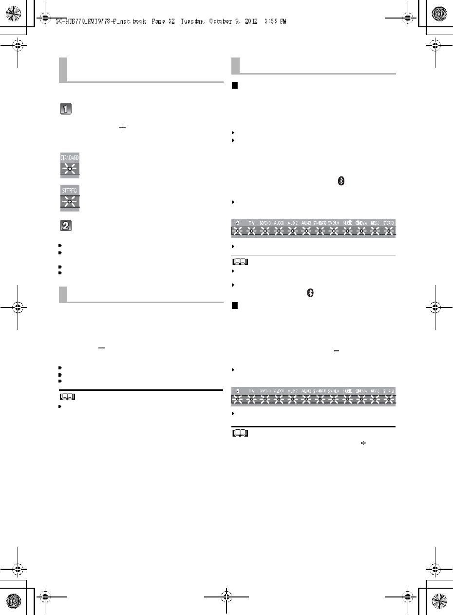
Indicator illumination
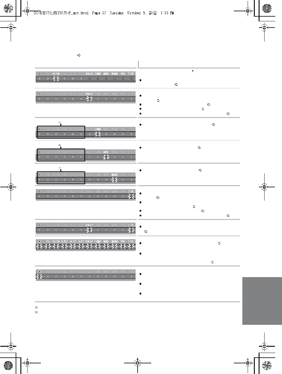
The indicators display the condition of this unit by flashing. The indicator patterns illustrated below are
displayed during normal operational conditions. They do not refer to the indications of a problem. Refer
to Troubleshooting ( 33) if the indicators do not light up as illustrated below.
1 The selected source indicator will also light.
2 The BD/DVD indicator stops blin king and lights once the wireless pair ing is successful.
Indicator Description
The BD/DVD indicator blinks 2 and soun d mo de
indicators light up in sequence for 1 minute.
When the main unit is in wireless pairing mode with the
active subwoofe r ( 35)
The indicator blinks for 20 sec.
When 3D surround effect and clea r-mode dialog effect
are on ( 32)
When the dual audio setting is Ma in ( 31)
When the auto gain control is on ( 31)
When the Bluetooth® communication i s mode 1 ( 31)
The indicators blink for 5 sec.
When the audio format is Dolby Digital ( 31)
The indicator blinks for 5 sec.
When the audio format is DTS ( 31)
The indicators blink for 5 sec.
When the audio format is PCM ( 31)
The indicator blinks for 20 sec.
When 3D surround effect and clea r-mode dialog effect
are off ( 32)
When the dual audio setting is Secondary (SAP:
Secondary Audio Program) ( 31)
When the auto gain control is off ( 31)
When the Bluetooth® communication i s mode 2 ( 31)
The indicators blink for 20 sec.
When the dual audio setting is Ma in and Secondary
(31)
The indicators blink for 10 sec.
When the remote control code is changed ( 32)
The indicators blink once.
When changing the setting (To reduce the clear- mode
dialog effect, To turn off VIERA Link HDAVI Control,
and To turn off the volume limitation) ( 32)
B lu eto oth® indicator blinks quickly.
When the main unit is rea dy for pairing
B lu eto oth® indicator blinks slowly.
When the main unit is waiting to connect
B lu eto oth® indicator turns on.
When the main unit is connected with a Bluetooth®
device
38 R QT977 8
Limited Warranty
(ONLY FOR U.S.A. AND PUERTO RICO)
Panasonic Consumer Marketing Company of North America,
Division of Panasonic Corporation of North America
One Pa nasonic Way, Secaucus, New Je rse y 070 94
Panasonic Products Limited Warranty
Limited Warranty Coverage
(For USA and Puerto Rico Only)
If your product does not work properly because of a defect in materials or
workmanship, Panasonic Consumer Marketing Company of North America
(referred to as the warrantor) will, for the length of the period indicated on
the chart below, which starts with the date of original purchase (warranty
period), at its option either (a) repair your product with new or refurbished
parts, (b) replace it with a new or a refurbished equivalent value product, or
(c) refund your purchase pr ice. The decision to repair, replace or refund will
be made by the warrantor.
During the Labor warranty period there will be no charge for labor. During
the Parts warranty per iod, there will be no charge for parts. This Limited
Warranty excludes both parts and labor for non-rechargeable batteries,
antennas, and cosmetic parts (cabinet). This warranty only applies to
products purchased and ser viced in the United States or Puerto Rico. This
warranty is extended only to the original purchaser of a new product which
was not sold as is.
Mail-In Service
For assistance in the U.S.A. and Puerto Rico in obtaining repairs, please
ship the product prepaid to:
Pan asonic Exchange Center
4900 George McVay Drive
Suite B
McAllen , TX 78503
panacare@us.panasonic.com
Online Repair Request
To submit a new repair request and for quick repair status visit our Web Site
at www.panasonic.com/repair.
When shipping the unit, carefully pack, include all supplied accessories listed
in the Owners Manual, and send it prepaid, adequately insured and packed
well in a carton box. When shipping Lithium Ion batteries please visit our
Web Site at www.panasonic.com/BatteryHandling as Panasonic is
committed to providing the most up to date information. Include a letter
detailing the complaint, a r eturn address and provide a daytime phone
number where you can be reached. A valid registered receipt is required
under the Limited War ranty.
IF REPAIR IS NEED ED DURING THE WARRAN TY PER IOD, THE
PURCHA SER WIL L BE REQ UIRED TO FURN ISH A SALES RECEIPT/
PROOF OF PURCHA SE INDICATIN G DATE OF PURCH ASE, AMOUNT
PAID AND PLAC E OF PUR CHASE. CUSTOMER WIL L BE CHA RGED
FOR TH E REPAIR OF ANY UNIT R EC EIVED WITHOUT SUCH PROOF
OF PURCHA SE.
Limited Warranty Limits And Exclusions
This warranty ONLY COVERS failures due to defects in materials or
workmanship, and DOES NOT COVER normal wear and tear or cosmetic
damage. The warranty ALSO DOES NOT COVER damages which occurred
in shipment, or failures which are caused by products not supplied by the
warrantor, or failures which result from accidents, misuse, abuse, neglect,
mishandling, misapplication, alteration, faulty installation,
set-up adjustments, misadjustment of consumer controls, improper
maintenance, power line surge, lightning damage, modification, introduction
of sand, humidity or liquids, commercial use such as hotel, office, restaurant,
or other business or rental use of the product, or service by anyone other
than a Factory Service Center or other Authorized Servicer, or damage that
is attributable to acts of God.
THERE A RE NO EXPRESS WARRANTIES EXCEPT AS LISTED
UND ER LIMIT ED WARRANTY COVERAG E.
THE WARRA NTOR IS N OT LIABLE FOR INCIDENTAL OR
CONSEQUENT IAL DA MAGES RESULTING FROM THE U SE OF TH IS
PRODUCT, OR ARISING OUT OF ANY BREACH O F THIS
WA RRANT Y.
(As examples, this excludes damages for lost time, travel to and from the
servicer, loss of or damage to media or images, data or other memory or
recorded content. The items listed are not exclusive, but for illustration only.)
ALL EXPR ESS AND IMPL IED WARRA NTIES, INCLU DING THE
WA RRANT Y OF MERC HANTABIL ITY, ARE L IMITED TO THE PERIOD
OF THE L IMITED WA RRANT Y.
Some states do not allow the exclusion or limitation of incidental or
consequential damages, or limitations on how long an implied warranty lasts,
so the exclusions may not apply to you.
This warranty gives you specific legal rights and you may also have other
rights which vary from state to state. If a problem with this product develops
during or after the warranty period, you may contact your dealer or Service
Center. If the problem is not handled to your satisfaction, then write to the
warrantors Consumer Affairs Department at the addresses listed for the
warrantor.
PAR TS AND SERVICE, WHICH ARE NOT C OVERED BY THIS
LIMITED WARR ANTY, A RE YOUR RESPON SIB ILITY.
As of October 2012
Product or Part Name Parts Labor
Home Theater Audio System 1 year 1 year
All included Accessories
(Except Non-Rechargeable Batteries) 90 days Not
Applicable
Only Non-Rechargeable Batteries 10 days Not
Applicable
Customer Services Directory (United States and Puerto Rico)
Obtain Pro duct Informatio n and Operating Assistance; locate
your nearest Dealer or Service Center; purch ase Parts and
Accessories; or make Customer Service an d Literature requests
by visiting our Web Site at:
http://www.p anasonic.com/help
or, contact us via the web at:
ht tp ://www.p anasonic.com/ contact inf o
You may also contact us directly at:
1-800-211-PANA (7262)
Monday-Friday 9am-9pm,
Saturday-Sunday 10am-7pm EST
For hearing or speech impaired TTY users, TTY: 1-877-833-8855
Acce ssory Purchases (Unite d Sta te s and Puerto Rico)
Purchase Parts, Accessories and Instruction Books online for all
Panasonic Products by visiting our Web Site at:
http://www.pstc.panasonic.com
Or, send your request by E-mail to:
npcparts@us.panasonic.com
You may also contact us directly at:
1-800-332-5368 (Phone) 1-800- 237-9080 (Fax Only)
(Monday-Friday 9am-9pm EST)
Panasonic National Parts Center
20421 84th Ave S., Kent, WA 98032
(We accept Visa, MasterCard, Discover Card, American Express)
For hearing or speech impaired TTY users, TTY: 1-866-605-1277
The mo del number an d serial nu mber of t hi s pr odu ct can be
fo und on eithe r the back o r t he b ott om of th e u nit.
Please no te th em in th e spa ce provi ded below and keep fo r fu tur e
r efer en ce.
MODEL NUMBER SC-HTB770
SERIA L NUMBER
User memo:
DATE OF PURCHA SE _ ___ ___ ___ ___ __ ___ ___ ___ ___ __ _
DEA LER NAME ___ ___ ___ __ ___ ___ ___ ___ ___ __ ___ ___ _
DEA LER ADDRESS ___ __ ___ ___ ___ ___ ___ ___ __ ___ ___ _
__ ___ ___ __ ___ ___ ___ ___ __ ___ ___ ___ ___ __ ___ ___ ___ __
TELEPHONE NUMBER ___ ___ __ ___ ___ ___ ___ ___ __ ___ _
R QT977 8 39
Limited Warranty (
ONLY FOR
CANADA)
Panasonic Canada Inc.
5770 Ambler Drive, Mississauga, Ontario L4W 2T3
PANASONIC PRODUCT - LIMITED WARRANTY
Panasonic Canada Inc. warrants this prod uct to be free from defects in material and workma nship under normal use
and for a period as stated below from the date of original purchase agrees to, at its option either (a) repair your product
with new or refurbished parts, (b) replace it with a new or a refurbi shed equivalent value product, or (c) refun d your
purchase price. The decision to repair, replace or refund will be made by Panasonic Canada Inc.
Technics Audio Product - One (1) year, parts and labour
Panasonic BD/DVD Product - One (1) year, parts and labour
Panasonic Audio Receivers - One (1) year, parts and labour
Home Theater Systems Product - One (1) year, parts and labour
This war ranty is given only to the orig inal purch aser, or the person for whom it was purchased as a gift, of a Panasonic
brand product me ntioned above sold by an authorized Panasonic dealer in Canada and purchased and used in
Canada, which product was not sol d as is, and which product was delivered to you in new condition in the original
packaging.
IN ORDER TO BE ELIGIBLE TO RECEIVE WARRANTY SERVICE HEREUNDER, A PURCHASE RECEIPT OR
OT HER P ROOF OF DATE OF ORIGINA L PU RC HASE, SHOW ING AMOU NT PAI D AN D PL ACE OF PURCHASE IS
REQUIRED
LIMITATIONS AND EXCLUSIONS
This war ranty ONLY COVERS failures due to defects in materials or wor kmanship, and DOES NOT COVE R normal
wear and tear or co smetic damage. The warranty ALS O DOES NOT COVER damages which occurred in shipment, or
failures which are caused by products not supplied by Panasonic Canada Inc., or failures which result from accidents,
misuse, abuse, negle ct, mishandling, misapplication, alteration, faulty installation, set-up adju stments, misadjustment of
consumer controls, impr oper maintenance , power line sur ge, lightning damage, mo dification, introdu ction of sand,
humidity or liquids, commercial use such as hotel, office, restaurant, or other business or renta l use of the product, or
service by anyone other than an Authorized Servicer, or damage that is attributable to acts of God.
Dry cell batteries are also excluded from coverage under this warranty.
THIS EXPRESS, LIMITED WARRANTY IS IN L IEU OF ALL OTHER WARRANTIES, EXPRESS OR IMPLIED,
INCLUDING ANY IMPLIED WARRANTIES OF MERCHANTABILITY AND FITNESS FOR A PARTICULAR PURPOSE.
IN NO EVENT WILL PANASONIC CANADA INC. BE LIABLE FOR ANY SPECIAL, INDIRECT OR CONSEQUENTIAL
DAMAGE S RESULTING FROM THE USE OF THIS PRODUCT OR ARISING OUT OF ANY BREACH OF ANY
EXPRESS OR IMPLIED WARRANTY. (As exampl es, this warranty excludes dama ges for lost time, travel to and from
the Authorized Servicer, l oss of or damage to media or ima ges, data or other memory or recorde d content. This list of
items is not exha ustive, but for illustration o nly.)
In certain instances, some jur isdictions do not allow th e exclusion or limitation of incidental or consequential da mages,
or the exclusion of implied warranties, so the above limitations and exclusions may not be applicable. This warr anty
gives you specific legal rights and you may have other rights which vary depending on your p rovince or territory.
WARRANTY SERVICE
For product operation and information assistance, please contact:
PRO DU CT OPERATION ASSISTAN CE
Customer Care Centre: Telephone #: 1-800-561 -5505
Fax #: (905) 238-2360
Email lin k: Supp ort contact us email on www.panasonic.ca
PRO DU CT REPAIRS
Please lo cate your nearest Author ized Servicentre.
Link: Support Panasonic Servicentre® locator on www.panasonic.ca
IF YOU SHIP THE PROD UCT T O A SE RVI CEN TRE
Carefully pack and send prepaid, a dequately insured and preferably i n the original carton.
Include details of the defect claimed, and proof of date of original purchase.
RQT9778-P
F1212RK 0
-If you see this symbol-
Inform ation o n Disposal in other Countries outside the
Euro pean Union
This symbol is only valid in the European Union.
If you wish to discard this product, please contact
your local authorities or dealer and ask for the
correct method of disposal.