Panasonic of North America 96NKX-UDS124 DECT 6.0 Cordless Telephone Base Station for SIP server or PBX User Manual Installation Guide English
Panasonic Corporation of North America DECT 6.0 Cordless Telephone Base Station for SIP server or PBX Installation Guide English
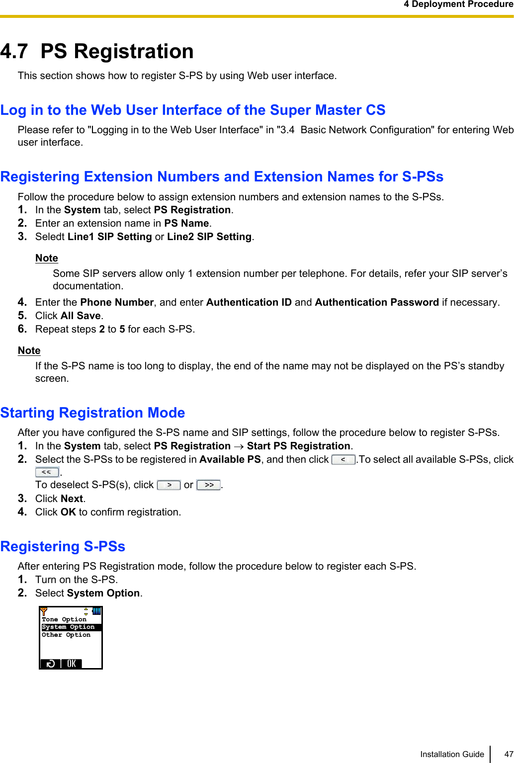
User manual
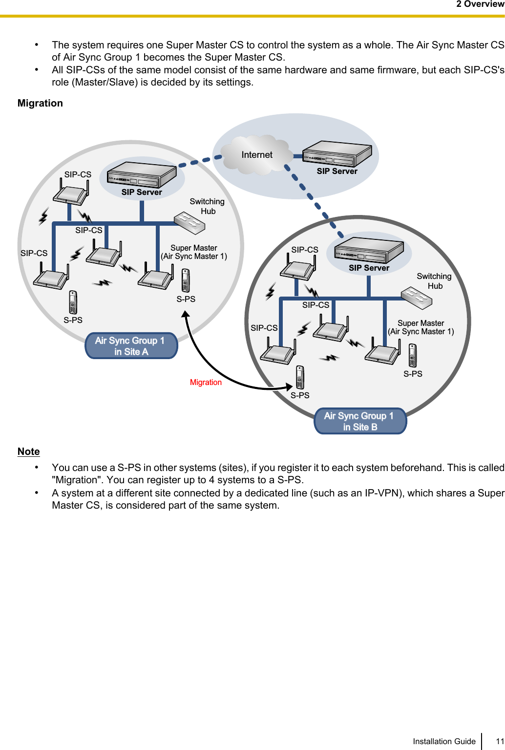
![•The SIP-CS must only be installed and serviced by qualified service personnel. The SIP-CS should beused as-is from the time of purchase; it should not be disassembled or modified. Disassembly ormodification can cause a fire, electric shock, or damage to the SIP-CS.•Make sure that the wall that the SIP-CS will be attached to is strong enough to support the SIP-CS (approx.330 g [11.6 oz]). If not, it is necessary for the wall to be reinforced.•Only use the wall-mounting equipment (screws, washers, wall mounting plate) included with the SIP-CS.•When the SIP-CS is no longer in use, make sure to detach it from the wall.•Disconnect the SIP-CS from the AC outlet, disconnect the LAN cable, and contact the dealer if:–The AC adaptor cord or AC plug becomes damaged or frayed.–The SIP-CS is exposed to rain, water, or any other liquid.–The SIP-CS is dropped or damaged.–Internal components are exposed due to damage.–The SIP-CS does not operate properly.–Performance deteriorates.•Disconnect the SIP-CS from the AC outlet and disconnect the LAN cable if the SIP-CS emits smoke, anabnormal smell, or makes unusual noise. These conditions can cause fire or electric shock. Confirm thatsmoke has stopped and contact an authorized service center.•Clean the AC plug periodically with a soft, dry cloth to remove dust and other debris.•If using an AC adaptor, use the optional AC adaptor KX-A239 (PQLV206YB), KX-A239X(PQLV206YB).•If damage to the SIP-CS exposes any internal parts, immediately disconnect the cable or cord. If the poweris supplied from the network to the SIP-CS (Power-over-Ethernet), disconnect the Ethernet cables.Otherwise, disconnect the AC adaptor cord. Then return the SIP-CS to a service center.•The SIP-CS should only be connected to a power supply of the type shown on the label on the SIP-CS.•Completely insert the AC adaptor/power plug into the AC outlet. Failure to do so may cause electric shockand/or excessive heat resulting in a fire.CAUTION•Do not stretch or bend the cables. Also, do not allow anything to rest on the cables.•Do not bundle cables that are connected to the SIP-CS with the AC power cords of machines locatednearby.•To prevent malfunction, deformity, overheating, rust, and discolouration, do not install or place equipmentin the following types of locations:–Locations where air ventilation is poor.–Locations that may be exposed to sulphurous gas, such as near hot springs.–Near devices that emit heat, such as heaters.–Near devices that emit electromagnetic noise, such as radios or televisions.–Near devices that emit high-frequency noise, such as sewing machines or welders.•The SIP-CS and the cables should never be placed near or over a radiator or other heat source.•The SIP-CS should not be placed outdoors (use indoors).•The SIP-CS should not be placed near high-voltage equipment.4 Installation Guide1 For Your Safety](https://usermanual.wiki/Panasonic-of-North-America/96NKX-UDS124/User-Guide-1708719-Page-4.png)
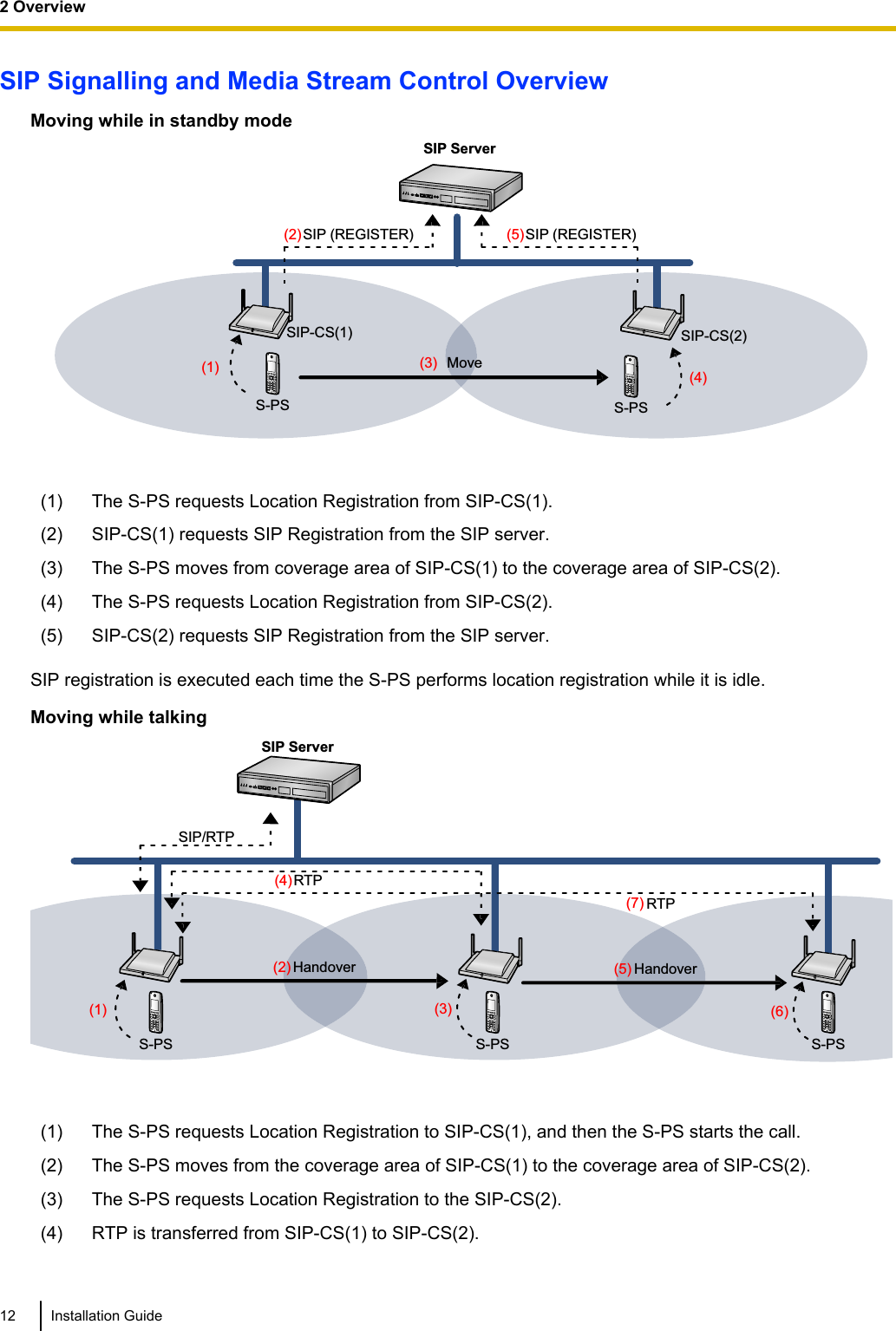
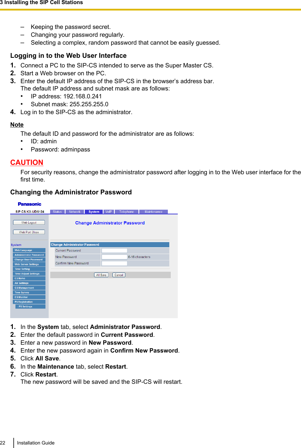
![•The SIP-CS should not be placed on a metal object.•The SIP-CS should be kept free of dust, moisture, high temperature (more than 40 °C [104 °F]), lowtemperature (less than 0 °C [32 °F]), and vibration, and should not be exposed to direct sunlight.•When driving the screws into the wall, be careful to avoid touching any metal laths, wire laths or metalplates in the wall.•Use cables that are fire-resistant or fireproof.•Make sure the cables are securely fastened to the wall.•The AC adaptor is used as the main disconnect device. Ensure that the AC adaptor is located near theSIP-CS and is easily accessible.•Disconnect the AC adaptor cord and all cables from the SIP-CS before cleaning. Clean the SIP-CS with asoft, dry cloth. Do not use liquid, aerosol cleaners, abrasive powders, or chemical agents to clean theSIP-CS.•When left unused for a long period of time, disconnect the SIP-CS from the AC outlet. When the SIP-CSreceives power from a PoE power supply, disconnect the LAN cable.•Medical—consult the manufacturer of any personal medical devices, such as pacemakers, to determineif they are adequately shielded from external RF (radio frequency) energy. (The SIP-CS operates in thefrequency range of 1920 MHz to 1930 MHz, and the output peak power level is less than 0.12 W.) Do notuse the SIP-CS in health care facilities if any regulations posted in the area instruct you not to do so.Hospitals or health care facilities may be using equipment that could be sensitive to external RF (radiofrequency) energy.•To ensure the security of private conversations, only connect the SIP-CS to a secure network.•To prevent unauthorized access, only connect the SIP-CS to a network that is properly managed.•Make sure all personal computers that are connected to the SIP-CS employ up-to-date security measures.•To avoid unauthorized access and possible abuse of your phone system, we strongly recommend:–Keeping the password secret.–Changing your password regularly.–Selecting a complex, random password that cannot be easily guessed.•Maintain the distances listed in "Required Distances between Equipment" in the Installation Guide betweenequipment in order to prevent noise, interference or the disconnection of a conversation. (The distancemay vary depending on the environment.)NoticeSAFETY REQUIREMENTS•Before connecting the SIP-CS, confirm that the SIP-CS supports the intended operating environment.•If the SIP-CS does not operate properly, disconnect the AC adaptor cord and LAN cable, then connectagain.•The SIP-CS may not operate in the event of a power failure.•Do not move the SIP-CS while it is in use.•Satisfactory operation, interoperability, and compatibility cannot be guaranteed with all equipmentconnected to the SIP-CS, nor with all services provided by telecommunications providers over networksconnected to the SIP-CS.SECURITY REQUIREMENTS•Privacy of communications may not be ensured when using the wireless systems.•Keep a copy of all important data (such as your network information) before sending the machine forrepair.Installation Guide 51 For Your Safety](https://usermanual.wiki/Panasonic-of-North-America/96NKX-UDS124/User-Guide-1708719-Page-5.png)
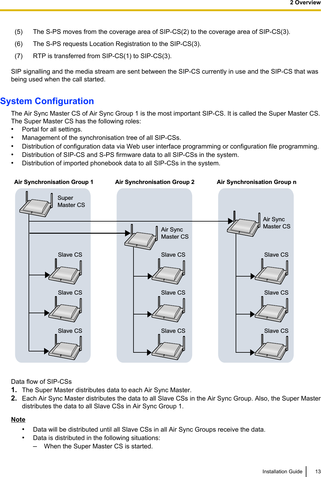
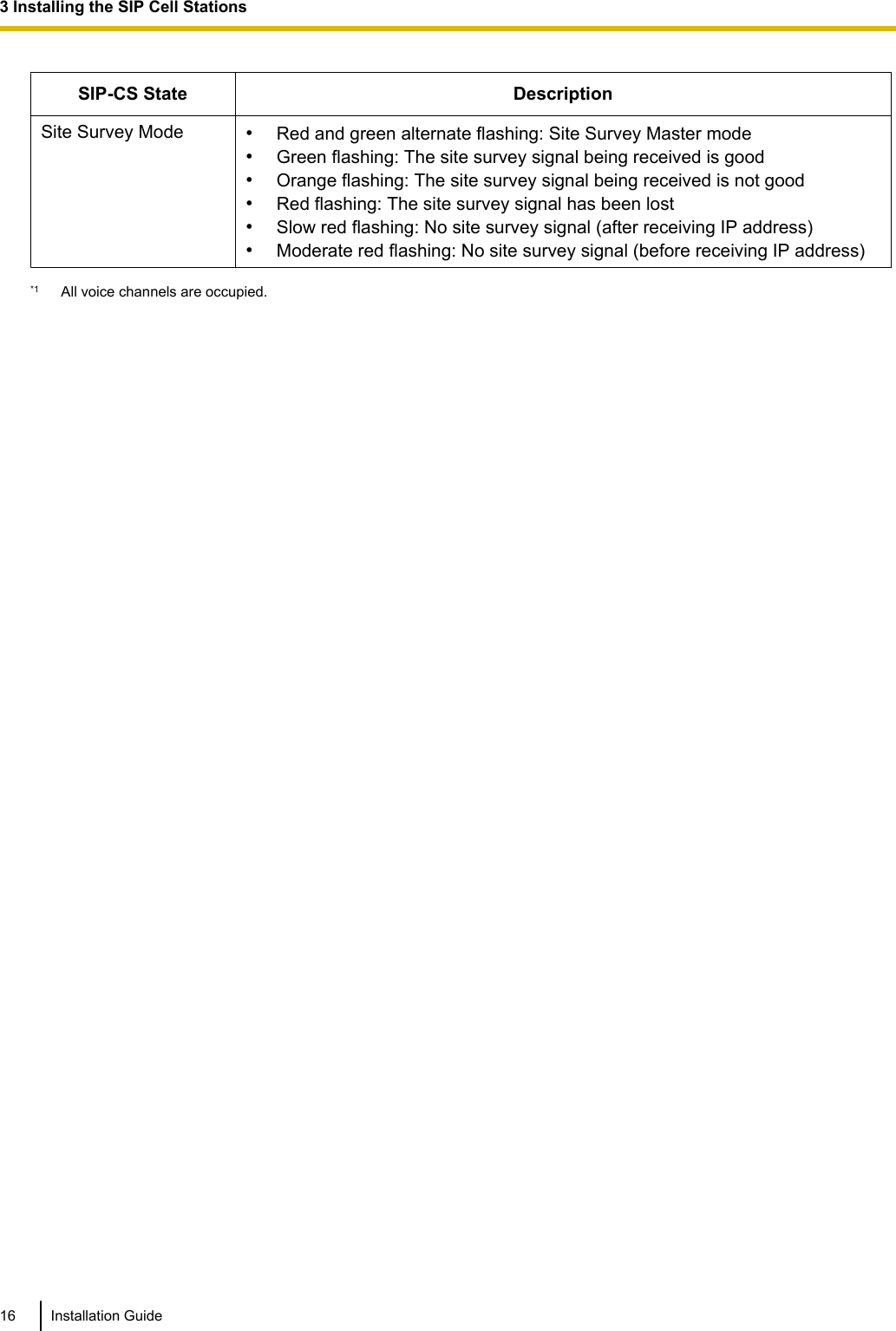
![3 Installing the SIP Cell Stations3.1 Overview of SIP Cell StationsNames and LocationsLEDAntennasCS ID Number(ID: xxxxxxxxxx)RJ45 ModularRESET SwitchDC JackMAC AddressUnpackingUnpack the box and check the items below:SIP Cell Station 1Wall Mounting Plate 1Screws 2Washers 2LED IndicationsSIP-CS State DescriptionGeneral Operation •OFF: Power Off/SIP-CS Software downloading•Green ON: Stand-by (no active calls)•Slow Green Flashing: Talk (active calls)•Moderate Green Flashing: Busy*1•Red ON: Fault•Slow Red Flashing: Out of Service/Starting up (data link establishment ® AirSynchronisation)•Moderate Red Flashing: Starting up (power on ® data link establishment)•Amber ON: Stand-by (unstable synchronisation [no active calls])•Slow Amber Flashing: Talk (unstable synchronisation [active calls])•Moderate Amber Flashing: Busy*1 (unstable synchronisation)NoteLED flashing patterns are as follows:•Slow Flashing: 60 times per minute•Moderate Flashing: 120 times per minuteInstallation Guide 153 Installing the SIP Cell Stations](https://usermanual.wiki/Panasonic-of-North-America/96NKX-UDS124/User-Guide-1708719-Page-15.png)
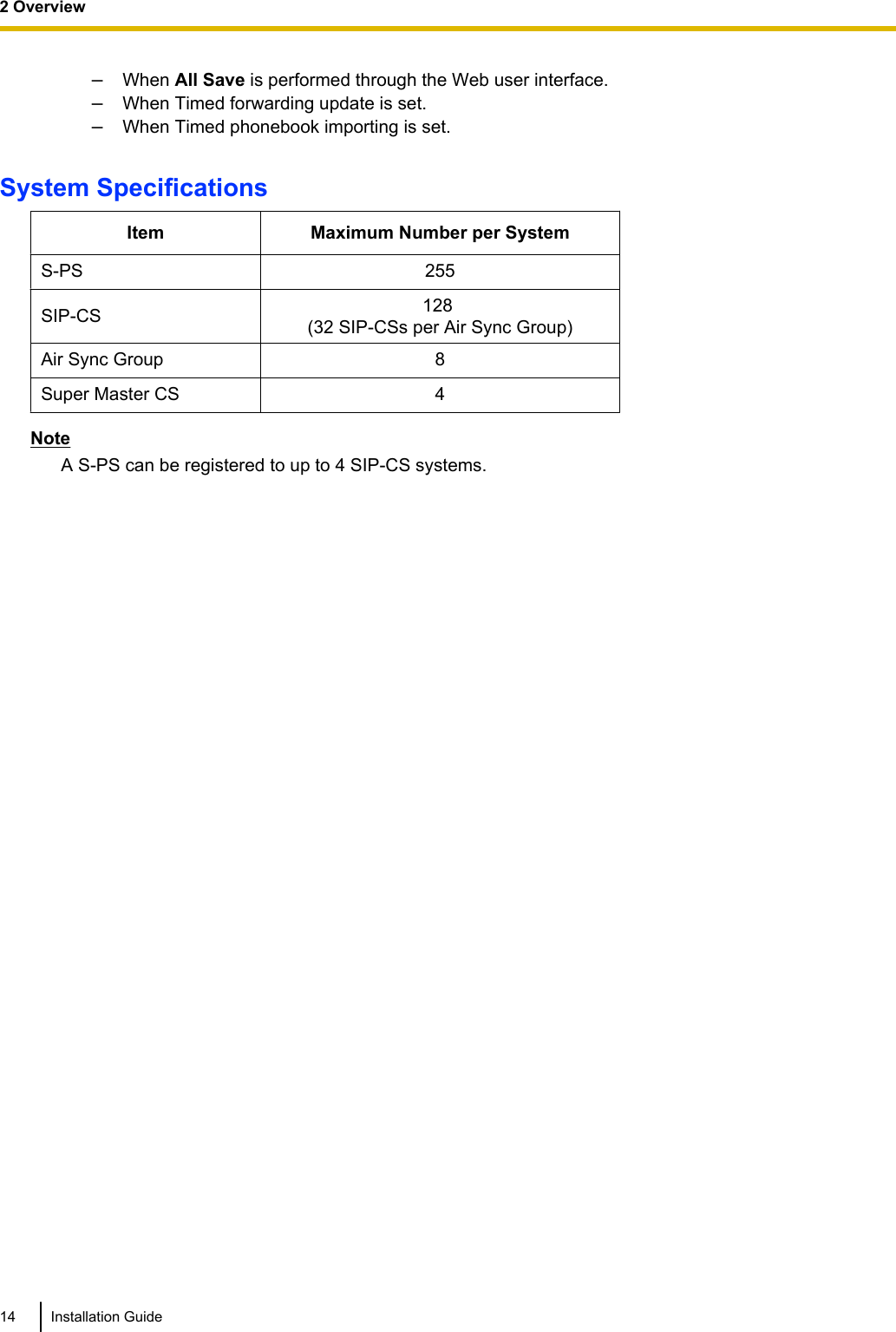
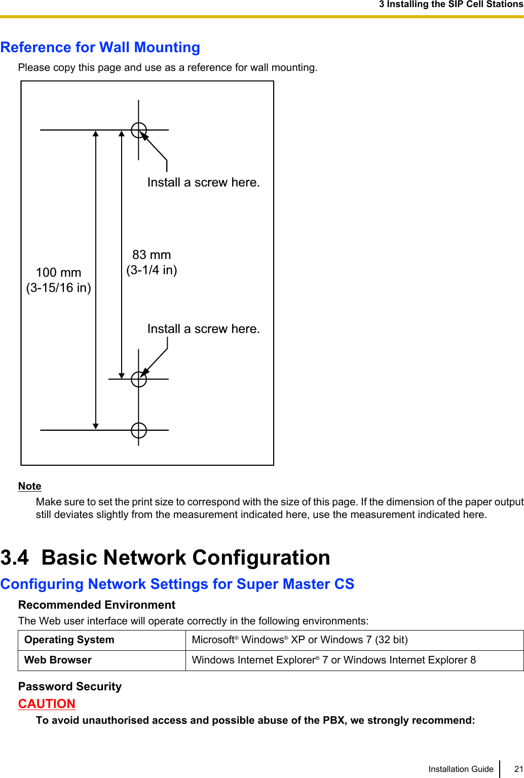
![3.3 Wall MountingMountingWARNING•Make sure that the wall that the CS will be attached to is strong enough to support the CS(approx. 330 g [11.6 oz]). If not, it is necessary for the wall to be reinforced.•Only use the wall-mounting equipment (screws, washers, wall mounting plate) included withthe CS.•When the CS is no longer in use, make sure to detach it from the wall.CAUTION•When driving the screws into the wall, be careful to avoid touching any metal laths, wire laths or metalplates in the wall.•Do not stretch or bend the cables. Also, do not allow anything to rest on the cables.•Use cables that are fire-resistant or fireproof.•The CS and the cables should never be placed near or over a radiator or other heat source.•Do not bundle cables that are connected to the CS with the AC power cords of machines locatednearby.•Make sure the cables are securely fastened to the wall.1. Place the reference for wall mounting on the wall to mark the 2 screw positions.2. Install the 2 screws and washers (included) into the wall.Note•Make sure that the screw heads are at the same distance from the wall.•Install the screws perpendicular to the wall.3. Insert the upper and lower tabs of the wall mounting plate into the designated openings in the base unit.TabsWall Mounting Plate (PSKL1032Y4)4. Slide the wall mounting plate in the direction of the arrow until it clicks.Installation Guide 193 Installing the SIP Cell Stations](https://usermanual.wiki/Panasonic-of-North-America/96NKX-UDS124/User-Guide-1708719-Page-19.png)
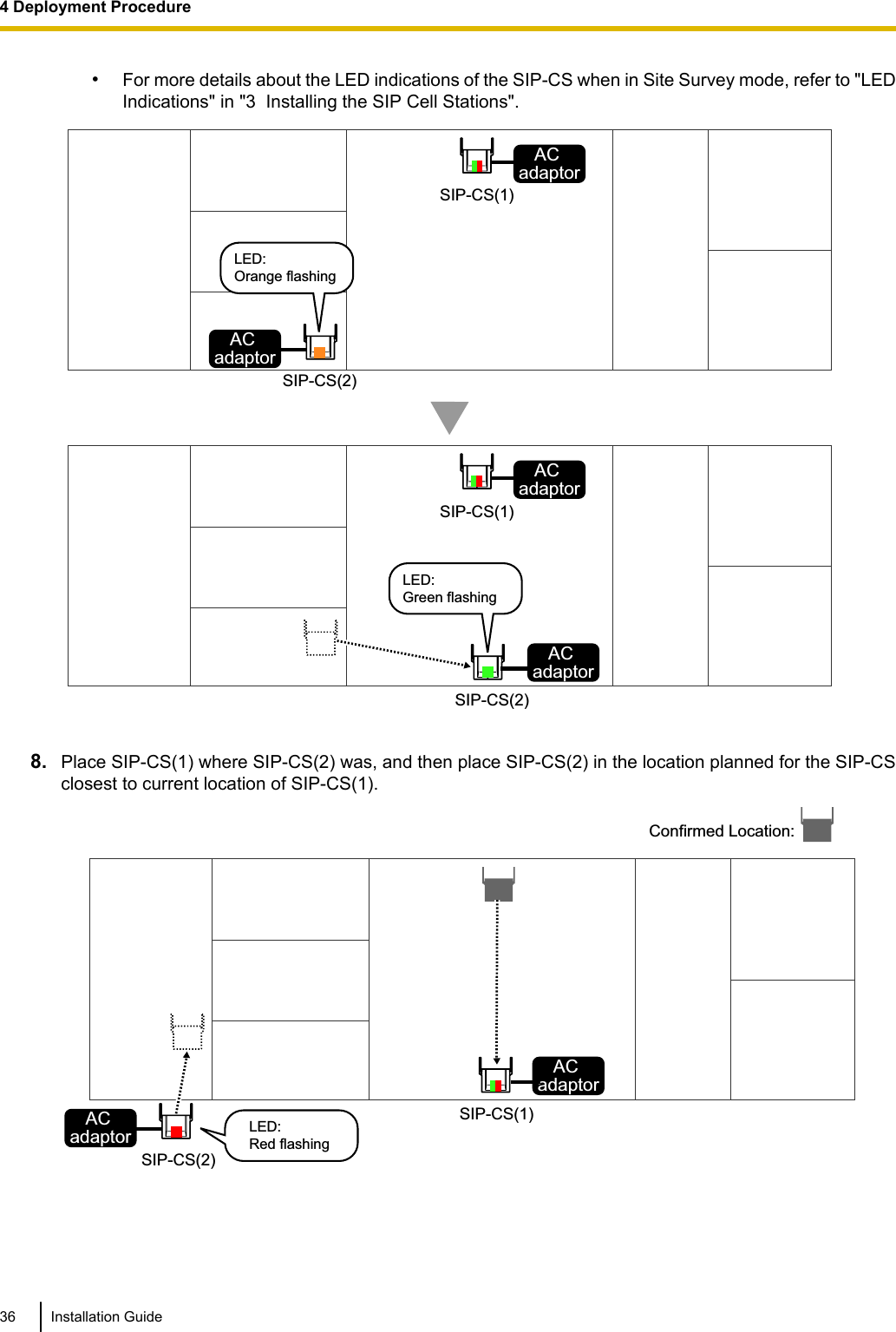
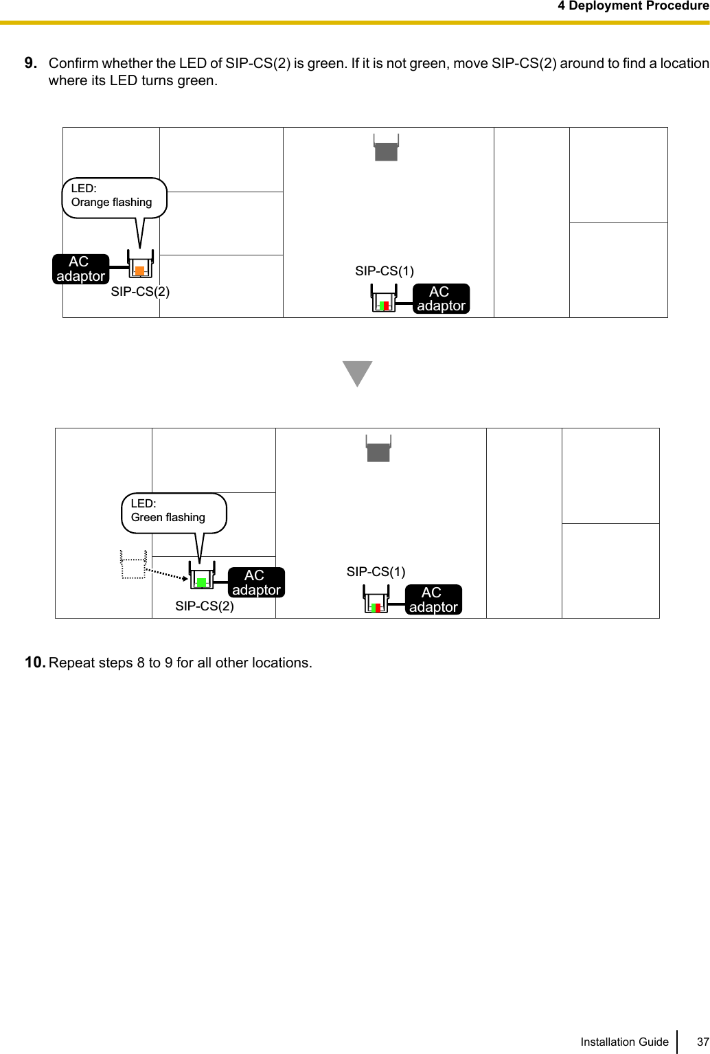
![3. Once SIP-CS(1) turns on, release the RESET switch, and then press the RESET switch again.SIP-CS(1) will enter Site Survey Master mode.4. Turn on SIP-CS(2) normally. SIP-CS(2) will enter Site Survey Slave mode automatically when it receivesa signal from SIP-CS(1).5. Place SIP-CS(1) where the Air Sync Master CS is planned to be located.Planned Location for Air Sync Master CSAC adaptor Planned Location:SIP-CS(1) (Site Survey Master Mode)LED:Red and green alternate flashing6. Place SIP-CS(2) in the location planned for the SIP-CS closest to the Air Sync Master CS (currentlySIP-CS[1]).AC adaptorAC adaptorSIP-CS(1) SIP-CS(2) (Site Survey Slave Mode)LED:Red flashing7. Confirm whether the LED of SIP-CS(2) is green.If it is not green, move SIP-CS(2) around to find a location where its LED turns green.Note•The LED indicates radio signal strength levels for air synchronisation. For details, refer to "CSCoverage Area for Establishing Conversations" in "4.2 Site Planning".Installation Guide 354 Deployment Procedure](https://usermanual.wiki/Panasonic-of-North-America/96NKX-UDS124/User-Guide-1708719-Page-35.png)
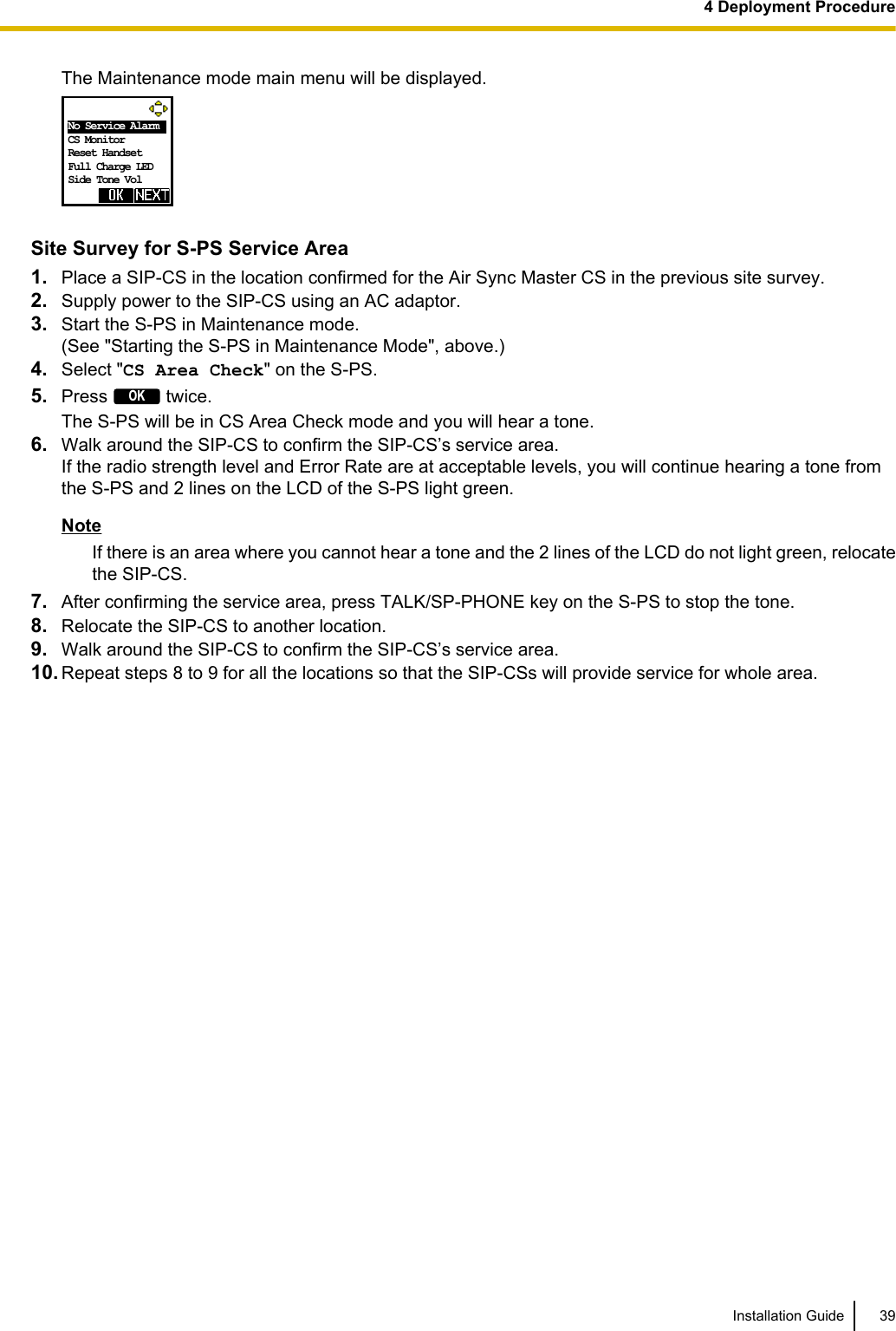
![Site Survey for S-PS Service AreaEach S-PS has a CS Area Check mode that monitors the state of the radio link to the SIP-CS to check theS-PS service area for establishing conversations. In CS Area Check mode, the following are displayed on theS-PS with a refresh interval of 2 seconds: the SIP-CS ID of the SIP-CS to which the S-PS is connected, theradio strength level, and the Error Rate. For each confirmed SIP-CS location, set the S-PS to CS Area Checkmode, and then place a SIP-CS at that location to measure the coverage area. Then, record the results on themap of the installation site. This site survey requires 1 S-PS and 1 SIP-CS.NoticeConduct the site survey starting with the confirmed location for Air Sync Master CS, and then go to closestlocation next.Before Site Survey for S-PS Service AreaChecking the SIP-CS ID NumberCheck the SIP-CS ID number label attached to the SIP-CS.The SIP-CS ID number is attached to the rear side of the SIP-CS.Starting the S-PS in Maintenance ModeThe S-PS must be in Maintenance mode to conduct a site survey.To enter Maintenance mode, follow the procedure below:NoteBefore using an S-PS, the battery must be inserted and then charged for the specified amount of time. Fordetails, refer to the documentation for the S-PS.1. The S-PS should be in a powered off state. If the S-PS is turned on, turn it off by pressing and holding thePOWER/CANCEL key.2. Turn on the S-PS by pressing and holding the POWER/CANCEL key. 3. After turning on the S-PS, a blank screen will be displayed. At this time, press and hold the TALK/SP-PHONE key for about 7 seconds, and then release the key.The S-PS will start in Maintenance mode. Maintenace Mode Ver.01.00 NoteWhen it takes more than 7 seconds to start Maintenance mode, follow the procedure below to returnstand by screen:a. Press the left soft key.b. Press [8] ® [1].The Maintenance mode main menu will be displayed.4. Press OK.38 Installation Guide4 Deployment Procedure](https://usermanual.wiki/Panasonic-of-North-America/96NKX-UDS124/User-Guide-1708719-Page-38.png)
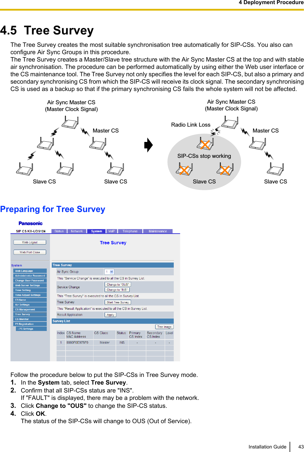
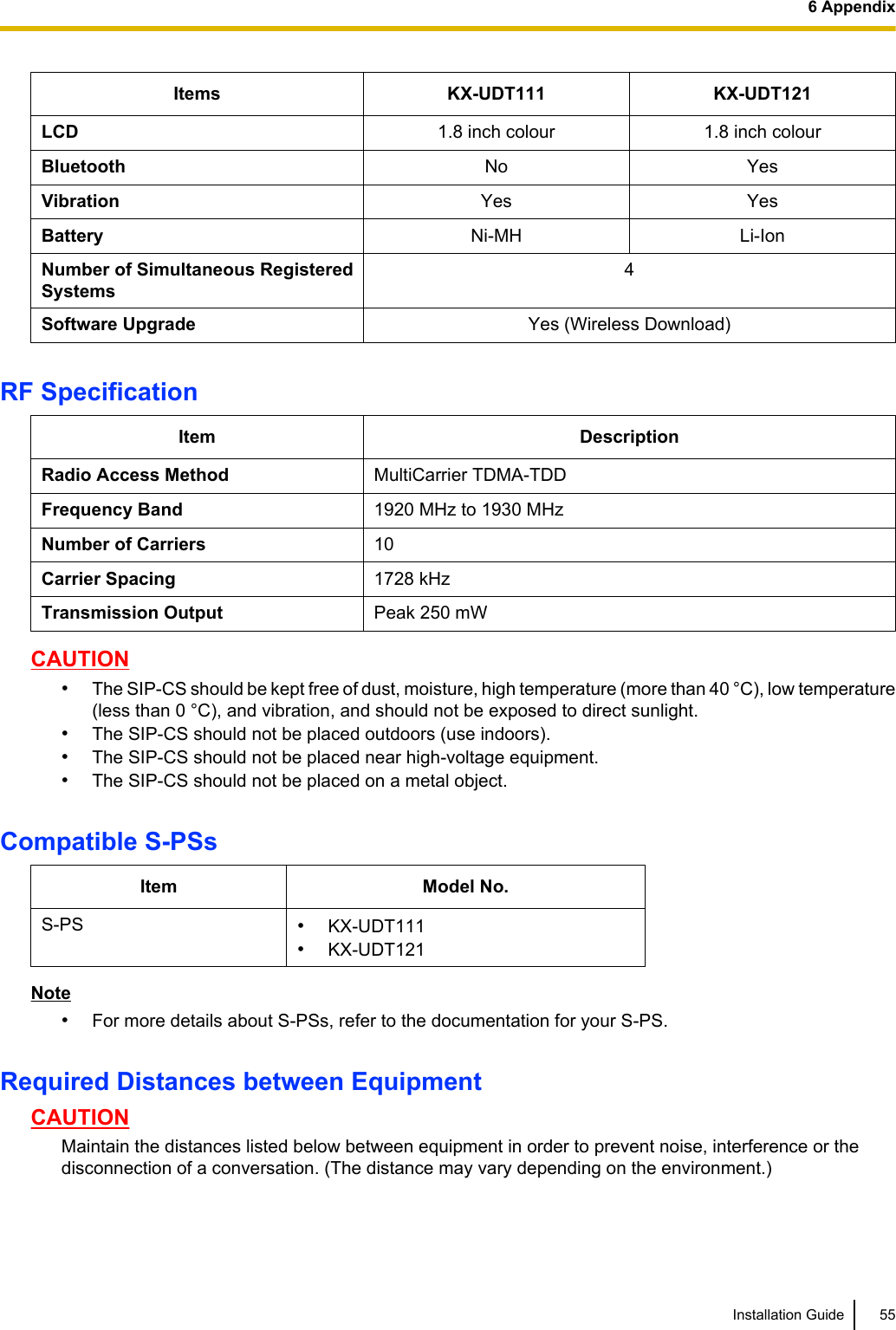
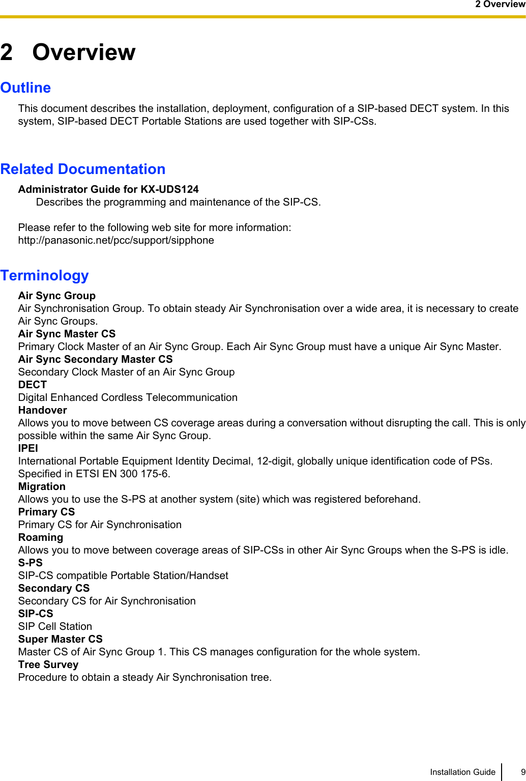
![6 AppendixSIP-CS SpecificationType 4 channel CS with wideband audioSupported Audio WidebandNarrowbandRadio Method DECTVoIP Signalling Protocol SIPIP Port Number Flexible Setting YesLocal Setting Yes (through Web application)Site Survey Mode Yes (through Web application)Initialisation Yes (through Web application)Maximum Simultaneous Calls 4Power Supply PoE (IEEE 802.3af)Optional AC adaptor(KX-A239 [PQLV206YB]/KX-A239X [PQLV206YB])Codec G.722 for Wideband(Used for LAN and broadband remote IP network)G.711 for Narrowband(Used for LAN and broadband remote IP network)G.729a for Narrowband(Used for narrowband remote IP network)LAN Port 10 BASE-T100 BASE-TXVLAN Yes (802.1Q)IP Addressing DHCPStatic IP Address SettingSoftware Upgrade YesBuilt-in VPN NoWeight 290 gSize (W) 190 mm ´ (H) 133.9 mm ´ (D) 39.3 mmPS SpecificationItems KX-UDT111 KX-UDT121Type Standard Slim & LightRadio Technology54 Installation Guide6 Appendix](https://usermanual.wiki/Panasonic-of-North-America/96NKX-UDS124/User-Guide-1708719-Page-54.png)