Panasonic of North America 96NKX-UDS124 DECT 6.0 Cordless Telephone Base Station for SIP server or PBX User Manual Installation Guide English
Panasonic Corporation of North America DECT 6.0 Cordless Telephone Base Station for SIP server or PBX Installation Guide English
User manual
Model No.
KX-UDS124
DECT 6.0 Cell Station Unit (SIP)
Installation Guide
Thank you for purchasing this Panasonic product.
Please read this manual carefully before using this product and save this manual for future use.
KX-UDS124: Software File Version 01.000 or later

Table of Contents
1 For Your Safety ........................................................................................3
2 Overview ...................................................................................................9
3 Installing the SIP Cell Stations .............................................................15
3.1 Overview of SIP Cell Stations ........................................................................................15
3.2 Connecting SIP Cell Stations .........................................................................................17
3.3 Wall Mounting ..................................................................................................................19
3.4 Basic Network Configuration .........................................................................................21
4 Deployment Procedure ..........................................................................25
4.1 Overview ..........................................................................................................................25
4.2 Site Planning ...................................................................................................................27
4.3 Site Survey .......................................................................................................................34
4.4 CS Registration ...............................................................................................................41
4.5 Tree Survey ......................................................................................................................43
4.6 Configuration ...................................................................................................................45
4.7 PS Registration ...............................................................................................................47
4.8 PS Area Check .................................................................................................................51
5 Troubleshooting .....................................................................................52
6 Appendix .................................................................................................54
2 Installation Guide
Table of Contents
1 For Your Safety
To prevent personal injury and/or damage to property, be sure to observe the following safety precautions.
The following symbols classify and describe the level of hazard and injury caused when this unit is
operated or handled improperly.
WARNING
This notice means that misuse could result in
death or serious injury.
CAUTION
This notice means that misuse could result in injury
or damage to property.
The following types of symbols are used to classify and describe the type of instructions to be
observed.
This symbol is used to alert users to a specific operating procedure that must not be performed.
This symbol is used to alert users to a specific operating procedure that must be followed in
order to operate the unit safely.
WARNING
•Do not connect or disconnect the AC plug with wet hands.
•Do not touch the SIP-CS, AC adaptor, or AC adaptor cord during a lightning storm.
•Do not allow anything to rest on the AC adaptor cord or LAN cable. Do not locate the SIP-CS where the
AC adaptor cord or LAN cable may be stepped on or tripped on.
•When installing or testing a SIP-CS with an external AC adaptor, the AC adaptor should be plugged into
a wall outlet or floor-mounted AC outlet. Do not connect the AC adaptor to a ceiling-mounted AC outlet, as
the weight of the adaptor may cause it to become disconnected.
•Make sure that you do not short the battery or cables.
•Never attempt to insert wires, pins, etc. into the vents or other holes of the SIP-CS.
•Do not splash water on the AC adaptor or the power cord, nor get them wet. Doing so can result in fire,
electric shock, or injury. If they do get wet, immediately disconnect the AC adaptor and power cord, and
contact an authorized service center.
•Do not touch the AC adaptor for extended periods of time. Doing so can lead to low-degree burns.
•Do not make power connections that exceed the ratings for the AC outlet or power equipment. If the power
rating of a surge protector, etc. is exceeded, it can cause a fire due to heat buildup.
•Care should be taken so that objects do not fall onto, and liquids are not spilled into, the SIP-CS. Do not
subject the SIP-CS to excessive smoke, dust, moisture, mechanical vibration, shock, or direct sunlight.
•Do not place heavy objects on top of the SIP-CS.
•Do not mount the SIP-CS in a manner other than that described in this manual.
Installation Guide 3
1 For Your Safety
•The SIP-CS must only be installed and serviced by qualified service personnel. The SIP-CS should be
used as-is from the time of purchase; it should not be disassembled or modified. Disassembly or
modification can cause a fire, electric shock, or damage to the SIP-CS.
•Make sure that the wall that the SIP-CS will be attached to is strong enough to support the SIP-CS (approx.
330 g [11.6 oz]). If not, it is necessary for the wall to be reinforced.
•Only use the wall-mounting equipment (screws, washers, wall mounting plate) included with the SIP-CS.
•When the SIP-CS is no longer in use, make sure to detach it from the wall.
•Disconnect the SIP-CS from the AC outlet, disconnect the LAN cable, and contact the dealer if:
–The AC adaptor cord or AC plug becomes damaged or frayed.
–The SIP-CS is exposed to rain, water, or any other liquid.
–The SIP-CS is dropped or damaged.
–Internal components are exposed due to damage.
–The SIP-CS does not operate properly.
–Performance deteriorates.
•Disconnect the SIP-CS from the AC outlet and disconnect the LAN cable if the SIP-CS emits smoke, an
abnormal smell, or makes unusual noise. These conditions can cause fire or electric shock. Confirm that
smoke has stopped and contact an authorized service center.
•Clean the AC plug periodically with a soft, dry cloth to remove dust and other debris.
•If using an AC adaptor, use the optional AC adaptor KX-A239 (PQLV206YB), KX-A239X(PQLV206YB).
•If damage to the SIP-CS exposes any internal parts, immediately disconnect the cable or cord. If the power
is supplied from the network to the SIP-CS (Power-over-Ethernet), disconnect the Ethernet cables.
Otherwise, disconnect the AC adaptor cord. Then return the SIP-CS to a service center.
•The SIP-CS should only be connected to a power supply of the type shown on the label on the SIP-CS.
•Completely insert the AC adaptor/power plug into the AC outlet. Failure to do so may cause electric shock
and/or excessive heat resulting in a fire.
CAUTION
•Do not stretch or bend the cables. Also, do not allow anything to rest on the cables.
•Do not bundle cables that are connected to the SIP-CS with the AC power cords of machines located
nearby.
•To prevent malfunction, deformity, overheating, rust, and discolouration, do not install or place equipment
in the following types of locations:
–Locations where air ventilation is poor.
–Locations that may be exposed to sulphurous gas, such as near hot springs.
–Near devices that emit heat, such as heaters.
–Near devices that emit electromagnetic noise, such as radios or televisions.
–Near devices that emit high-frequency noise, such as sewing machines or welders.
•The SIP-CS and the cables should never be placed near or over a radiator or other heat source.
•The SIP-CS should not be placed outdoors (use indoors).
•The SIP-CS should not be placed near high-voltage equipment.
4 Installation Guide
1 For Your Safety

•The SIP-CS should not be placed on a metal object.
•The SIP-CS should be kept free of dust, moisture, high temperature (more than 40 °C [104 °F]), low
temperature (less than 0 °C [32 °F]), and vibration, and should not be exposed to direct sunlight.
•When driving the screws into the wall, be careful to avoid touching any metal laths, wire laths or metal
plates in the wall.
•Use cables that are fire-resistant or fireproof.
•Make sure the cables are securely fastened to the wall.
•The AC adaptor is used as the main disconnect device. Ensure that the AC adaptor is located near the
SIP-CS and is easily accessible.
•Disconnect the AC adaptor cord and all cables from the SIP-CS before cleaning. Clean the SIP-CS with a
soft, dry cloth. Do not use liquid, aerosol cleaners, abrasive powders, or chemical agents to clean the
SIP-CS.
•When left unused for a long period of time, disconnect the SIP-CS from the AC outlet. When the SIP-CS
receives power from a PoE power supply, disconnect the LAN cable.
•Medical—consult the manufacturer of any personal medical devices, such as pacemakers, to determine
if they are adequately shielded from external RF (radio frequency) energy. (The SIP-CS operates in the
frequency range of 1920 MHz to 1930 MHz, and the output peak power level is less than 0.12 W.) Do not
use the SIP-CS in health care facilities if any regulations posted in the area instruct you not to do so.
Hospitals or health care facilities may be using equipment that could be sensitive to external RF (radio
frequency) energy.
•To ensure the security of private conversations, only connect the SIP-CS to a secure network.
•To prevent unauthorized access, only connect the SIP-CS to a network that is properly managed.
•Make sure all personal computers that are connected to the SIP-CS employ up-to-date security measures.
•To avoid unauthorized access and possible abuse of your phone system, we strongly recommend:
–Keeping the password secret.
–Changing your password regularly.
–Selecting a complex, random password that cannot be easily guessed.
•Maintain the distances listed in "Required Distances between Equipment" in the Installation Guide between
equipment in order to prevent noise, interference or the disconnection of a conversation. (The distance
may vary depending on the environment.)
Notice
SAFETY REQUIREMENTS
•Before connecting the SIP-CS, confirm that the SIP-CS supports the intended operating environment.
•If the SIP-CS does not operate properly, disconnect the AC adaptor cord and LAN cable, then connect
again.
•The SIP-CS may not operate in the event of a power failure.
•Do not move the SIP-CS while it is in use.
•Satisfactory operation, interoperability, and compatibility cannot be guaranteed with all equipment
connected to the SIP-CS, nor with all services provided by telecommunications providers over networks
connected to the SIP-CS.
SECURITY REQUIREMENTS
•Privacy of communications may not be ensured when using the wireless systems.
•Keep a copy of all important data (such as your network information) before sending the machine for
repair.
Installation Guide 5
1 For Your Safety

•The SIP-CS can store your private/confidential information. To protect your privacy/confidentiality, we
recommend that you initialize the SIP-CS to erase all user data and restore the factory default settings
before you dispose, transfer or return the SIP-CS.
6 Installation Guide
1 For Your Safety

Additional Information
F.C.C. AND INDUSTRY CANADA RELEVANT INFORMATION
CAUTION
Any changes or modifications not expressly approved by the party responsible for compliance could void
the user's authority to operate this device.
Privacy of communications may not be ensured when using this unit.
Notice
FCC ID can be found on the back of this unit.
Note
This equipment has been tested and found to comply with the limits for a Class B digital device, pursuant
to Part 15 of the FCC Rules. These limits are designed to provide reasonable protection against harmful
interference in a residential installation. This equipment generates, uses, and can radiate radio frequency
energy and, if not installed and used in accordance with the instructions, may cause harmful interference
to radio communications. However, there is no guarantee that interference will not occur in a particular
installation. If this equipment does cause harmful interference to radio or television reception, which can
be determined by turning the equipment off and on, the user is encouraged to try to correct the interference
by one or more of the following measures:
•Reorient or relocate the receiving antenna.
•Increase the distance between the equipment and receiver.
•Connect the equipment to an outlet on a circuit different from that to which the receiver is connected.
•Consult the dealer or an experienced radio/TV technician for help.
Some wireless telephones operate at frequencies that may cause interference to nearby TVs and VCRs.
To minimize or prevent such interference, the base of the wireless telephone should not be placed near
or on top of a TV or VCR. If interference is experienced, move the wireless telephone further away from
the TV or VCR. This will often reduce, or eliminate, interference.
RF Exposure Warning:
This product complies with FCC/IC radiation exposure limits set forth for an uncontrolled environment. To
comply with FCC/IC RF exposure requirements, this product must be installed and operated in accordance
with the provided instructions. The installed unit requires a minimum 20 cm (8 inches) of spacing between the
antenna and a person’s body (excluding hands, wrists and feet) during wireless modes of operation.
This transmitter must not be co-located or operated in conjunction with any other antennas or transmitters.
For Users in Canada Only
This Class B digital apparatus complies with Canadian ICES-003.
Note
Operation is subject to the following two conditions: (1) this device may not cause interference, and (2) this
device must accept any interference, including interference that may cause undesired operation of the
device.
Privacy of communications may not be ensured when using this telephone. Some wireless telephones
operate at frequencies that may cause interference to nearby TVs and VCRs. To minimize or prevent such
interference, the base of the wireless telephone should not be placed near, or on top of, a TV or VCR. If
Installation Guide 7
1 For Your Safety

interference is experienced, move the wireless telephone further away from the TV or VCR. This will often
reduce, or eliminate, interference.
8 Installation Guide
1 For Your Safety

2 Overview
Outline
This document describes the installation, deployment, configuration of a SIP-based DECT system. In this
system, SIP-based DECT Portable Stations are used together with SIP-CSs.
Related Documentation
Administrator Guide for KX-UDS124
Describes the programming and maintenance of the SIP-CS.
Please refer to the following web site for more information:
http://panasonic.net/pcc/support/sipphone
Terminology
Air Sync Group
Air Synchronisation Group. To obtain steady Air Synchronisation over a wide area, it is necessary to create
Air Sync Groups.
Air Sync Master CS
Primary Clock Master of an Air Sync Group. Each Air Sync Group must have a unique Air Sync Master.
Air Sync Secondary Master CS
Secondary Clock Master of an Air Sync Group
DECT
Digital Enhanced Cordless Telecommunication
Handover
Allows you to move between CS coverage areas during a conversation without disrupting the call. This is only
possible within the same Air Sync Group.
IPEI
International Portable Equipment Identity Decimal, 12-digit, globally unique identification code of PSs.
Specified in ETSI EN 300 175-6.
Migration
Allows you to use the S-PS at another system (site) which was registered beforehand.
Primary CS
Primary CS for Air Synchronisation
Roaming
Allows you to move between coverage areas of SIP-CSs in other Air Sync Groups when the S-PS is idle.
S-PS
SIP-CS compatible Portable Station/Handset
Secondary CS
Secondary CS for Air Synchronisation
SIP-CS
SIP Cell Station
Super Master CS
Master CS of Air Sync Group 1. This CS manages configuration for the whole system.
Tree Survey
Procedure to obtain a steady Air Synchronisation tree.
Installation Guide 9
2 Overview
System Overview
The SIP-CS can be connected to a SIP server via a LAN and supports S-PSs for making calls. The SIP-CS
allows for easy and cost-saving installation using an existing IP network infrastructure. Air synchronisation
technology is used for synchronising each SIP-CS.
The SIP-CS provides the following:
–Wireless systems using a converged voice and data network infrastructure.
–Wireless branch offices and wireless solutions by long distance installation on larger premises when
located on the same network.
–Reliable wireless communication using DECT technology over an IP network.
–High quality voice communication.
–Easy maintenance using Air Download.
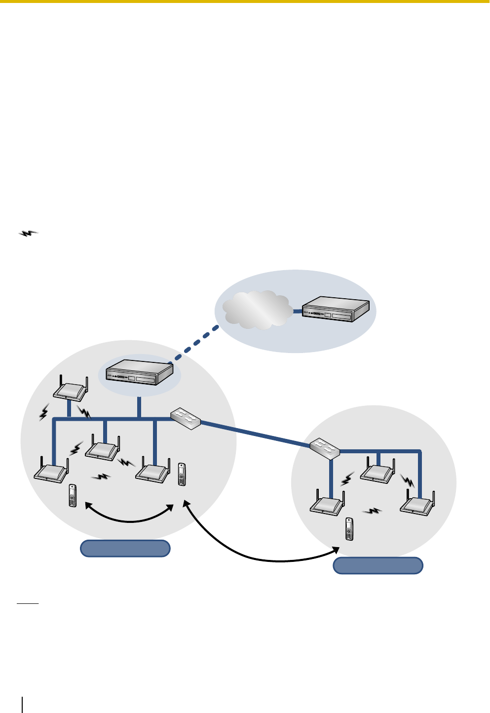
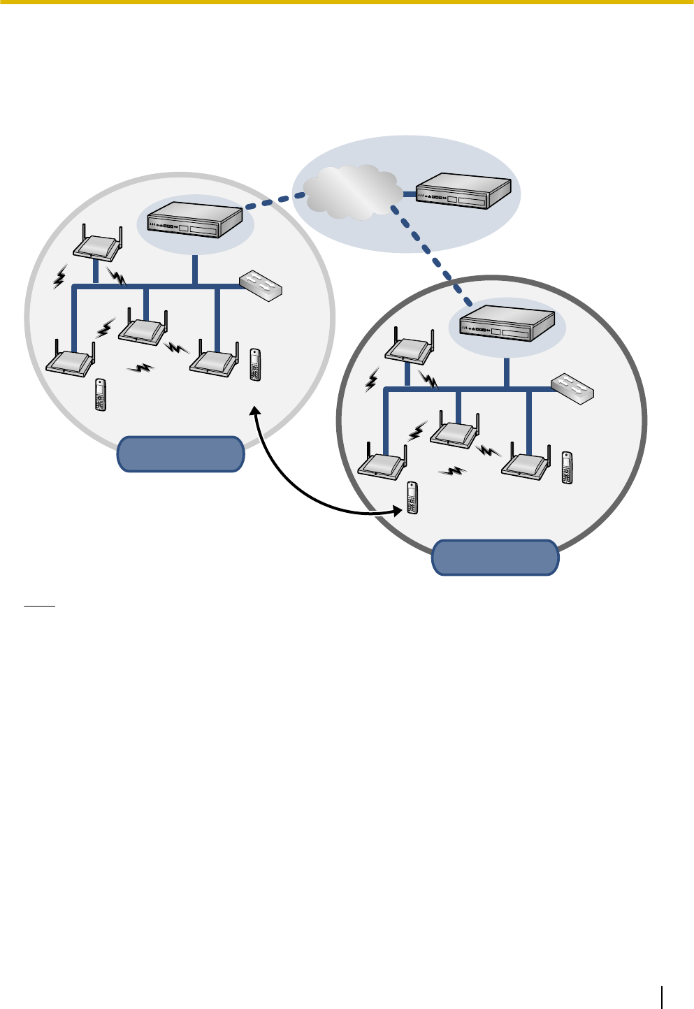
The following is an example of SIP-CS installation using an IP network.
To obtain steady Air Synchronisation, create two or more Air Sync Groups to cover a wide area, as shown
below.
: Handover is working.
Roaming
S-PS
Switching
Hub
SIP-CS
Super Master
(Air Sync Master 1)
SIP-CS
Air Sync Group 1
Air Sync Group 1
S-PS
Handover
SIP Server
SIP-CS
SIP Server
SIP-CS
Air Sync Group 2
Air Sync Group 2
Switching
Hub
SIP-CS SIP-CS
S-PS
Roaming
Internet
Note
•You can move between the coverage areas of SIP-CSs during a conversation, without disrupting the
call. This is called "Handover" and is only possible within the same Air Sync Group. You cannot move
between Air Sync Groups during a conversation. You can only move between Air Sync Groups when
in idle status. This is called "Roaming".
•Each Air Sync Group requires an Air Sync Master CS.
10 Installation Guide
2 Overview
•The system requires one Super Master CS to control the system as a whole. The Air Sync Master CS
of Air Sync Group 1 becomes the Super Master CS.
•All SIP-CSs of the same model consist of the same hardware and same firmware, but each SIP-CS's
role (Master/Slave) is decided by its settings.
Migration
S-PS
Switching
Hub
SIP-CS
Super Master
(Air Sync Master 1)
SIP-CS
Air Sync Group 1
Air Sync Group 1
in Site A
in Site A
S-PS
SIP-CS
S-PS
Switching
Hub
SIP-CS
Super Master
(Air Sync Master 1)
SIP-CS
Air Sync Group 1
Air Sync Group 1
in Site B
in Site B
S-PS
SIP Server
SIP-CS
SIP Server
Migration
Internet
SIP Server
Note
•You can use a S-PS in other systems (sites), if you register it to each system beforehand. This is called
"Migration". You can register up to 4 systems to a S-PS.
•A system at a different site connected by a dedicated line (such as an IP-VPN), which shares a Super
Master CS, is considered part of the same system.
Installation Guide 11
2 Overview
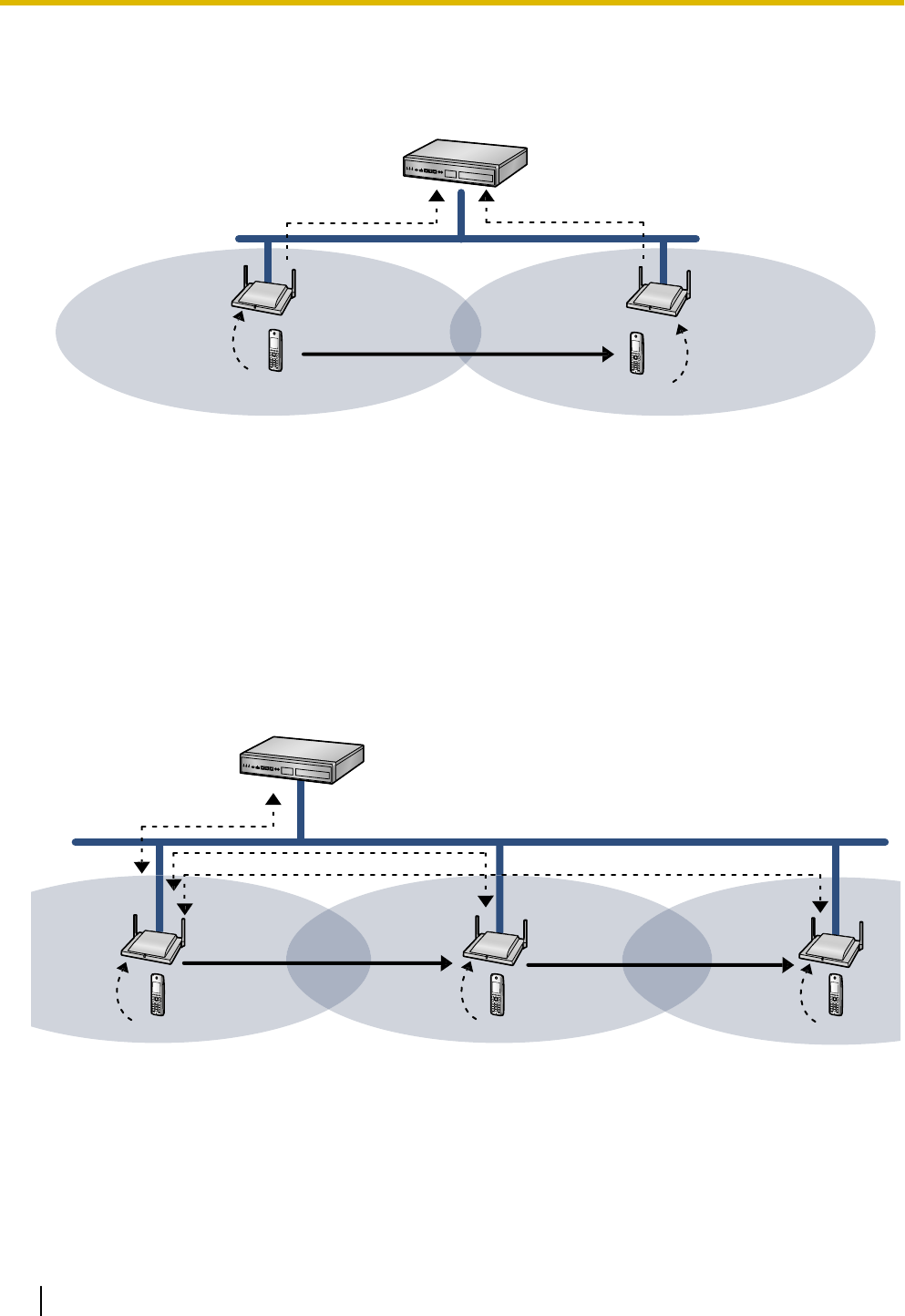
SIP Signalling and Media Stream Control Overview
Moving while in standby mode
SIP Server
S-PS S-PS
SIP (REGISTER)(2)
SIP-CS(1) SIP-CS(2)
(1) Move(3)
(4)
SIP (REGISTER)(5)
(1) The S-PS requests Location Registration from SIP-CS(1).
(2) SIP-CS(1) requests SIP Registration from the SIP server.
(3) The S-PS moves from coverage area of SIP-CS(1) to the coverage area of SIP-CS(2).
(4) The S-PS requests Location Registration from SIP-CS(2).
(5) SIP-CS(2) requests SIP Registration from the SIP server.
SIP registration is executed each time the S-PS performs location registration while it is idle.
Moving while talking
SIP Server
S-PS S-PS
SIP/RTP
(4)
Handover
(7)
Handover
S-PS
RTP
RTP
(1)
(2)
(3)
(5)
(6)
(1) The S-PS requests Location Registration to SIP-CS(1), and then the S-PS starts the call.
(2) The S-PS moves from the coverage area of SIP-CS(1) to the coverage area of SIP-CS(2).
(3) The S-PS requests Location Registration to the SIP-CS(2).
(4) RTP is transferred from SIP-CS(1) to SIP-CS(2).
12 Installation Guide
2 Overview
(5) The S-PS moves from the coverage area of SIP-CS(2) to the coverage area of SIP-CS(3).
(6) The S-PS requests Location Registration to the SIP-CS(3).
(7) RTP is transferred from SIP-CS(1) to SIP-CS(3).
SIP signalling and the media stream are sent between the SIP-CS currently in use and the SIP-CS that was
being used when the call started.
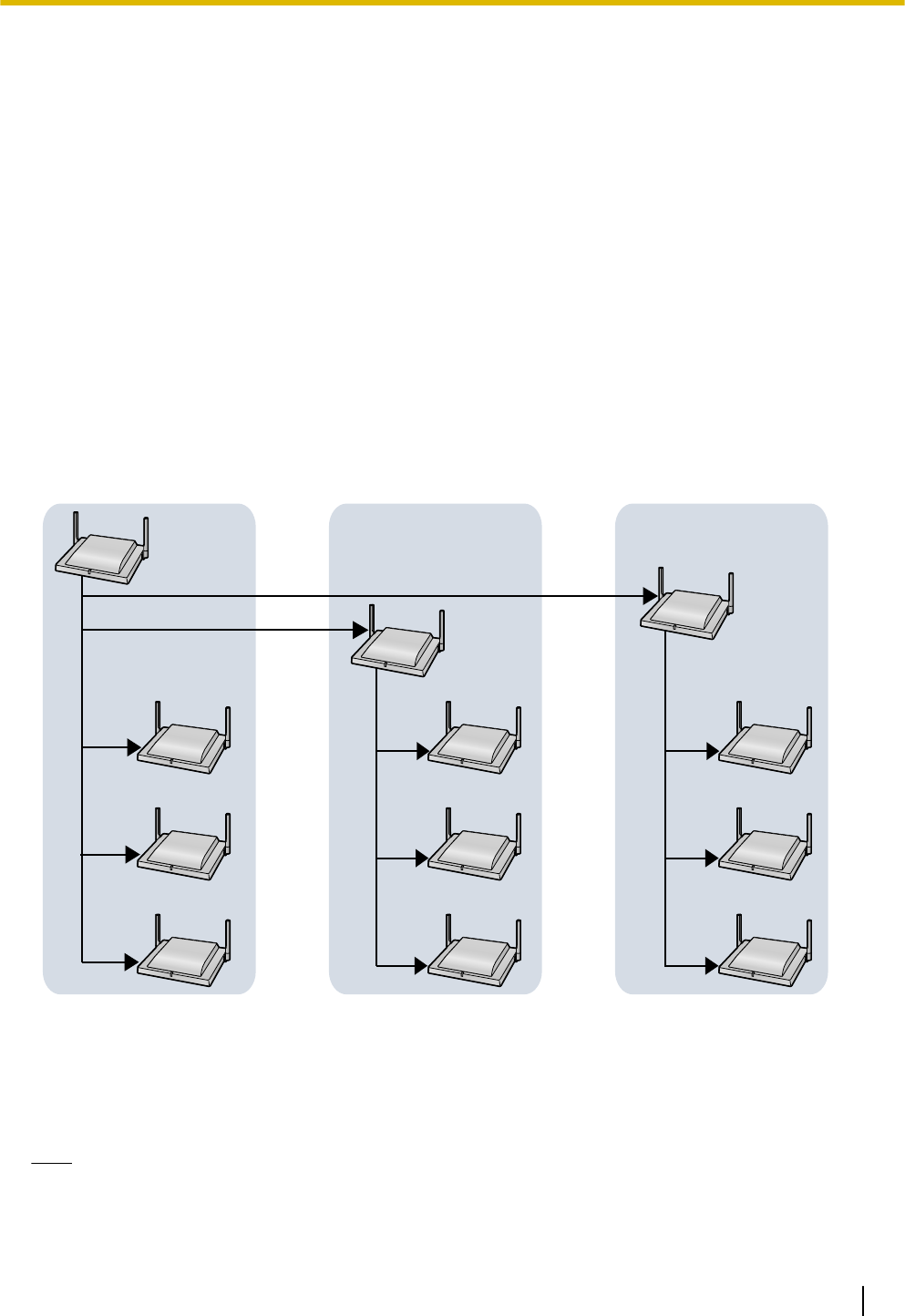
System Configuration
The Air Sync Master CS of Air Sync Group 1 is the most important SIP-CS. It is called the Super Master CS.
The Super Master CS has the following roles:
•Portal for all settings.
•Management of the synchronisation tree of all SIP-CSs.
•Distribution of configuration data via Web user interface programming or configuration file programming.
•Distribution of SIP-CS and S-PS firmware data to all SIP-CSs in the system.
•Distribution of imported phonebook data to all SIP-CSs in the system.
Super
Master CS
Air Synchronisation Group 1 Air Synchronisation Group 2 Air Synchronisation Group n
Air Sync
Master CS
Air Sync
Master CS
Slave CS
Slave CS
Slave CS
Slave CS
Slave CS
Slave CS
Slave CS
Slave CS
Slave CS
Data flow of SIP-CSs
1. The Super Master distributes data to each Air Sync Master.
2. Each Air Sync Master distributes the data to all Slave CSs in the Air Sync Group. Also, the Super Master
distributes the data to all Slave CSs in Air Sync Group 1.
Note
•Data will be distributed until all Slave CSs in all Air Sync Groups receive the data.
•Data is distributed in the following situations:
–When the Super Master CS is started.
Installation Guide 13
2 Overview

–When All Save is performed through the Web user interface.
–When Timed forwarding update is set.
–When Timed phonebook importing is set.
System Specifications
Item Maximum Number per System
S-PS 255
SIP-CS 128
(32 SIP-CSs per Air Sync Group)
Air Sync Group 8
Super Master CS 4
Note
A S-PS can be registered to up to 4 SIP-CS systems.
14 Installation Guide
2 Overview
3 Installing the SIP Cell Stations
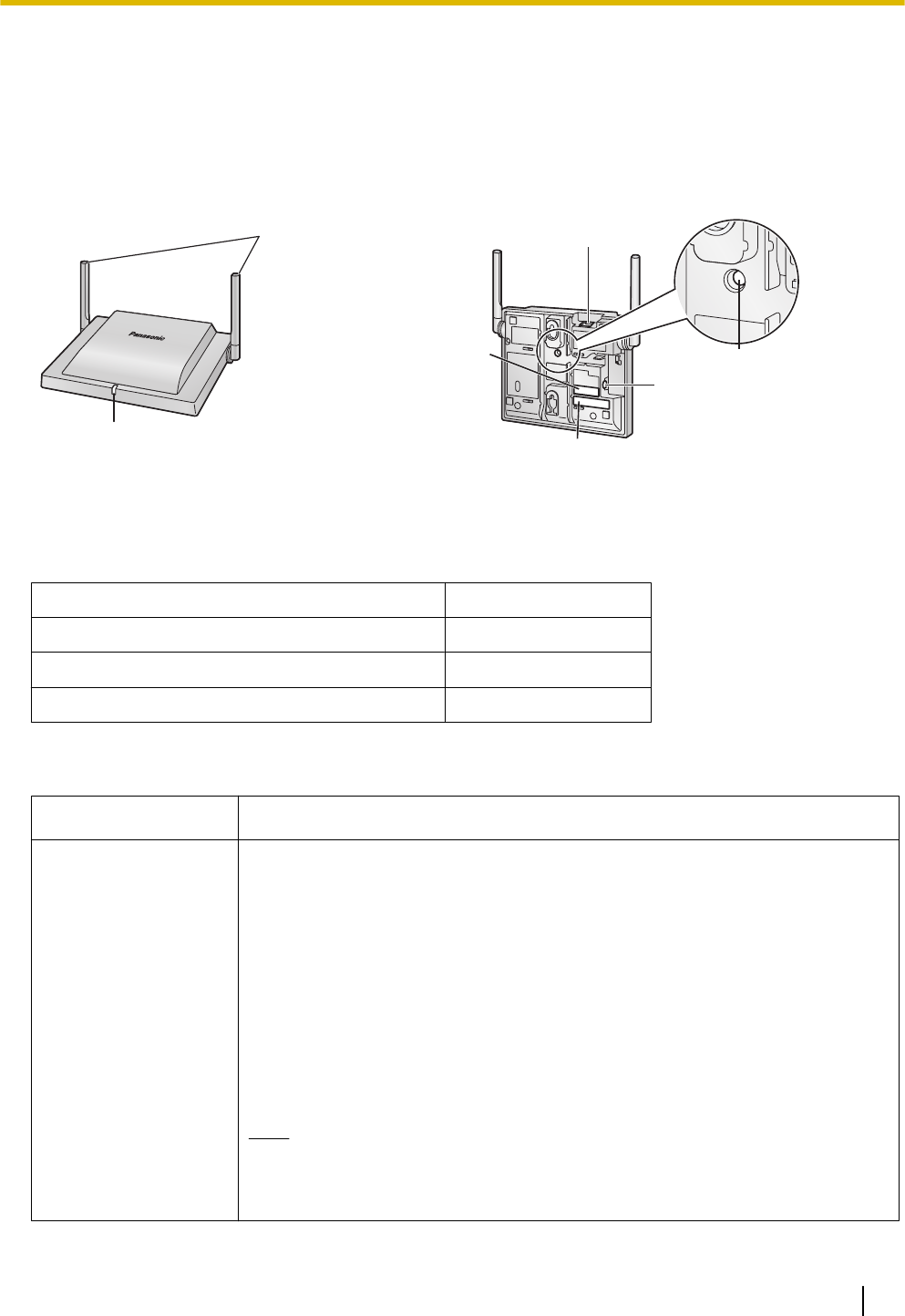
3.1 Overview of SIP Cell Stations
Names and Locations
LED
Antennas
CS ID Number
(ID: xxxxxxxxxx)
RJ45 Modular
RESET Switch
DC Jack
MAC Address
Unpacking
Unpack the box and check the items below:
SIP Cell Station 1
Wall Mounting Plate 1
Screws 2
Washers 2
LED Indications
SIP-CS State Description
General Operation •OFF: Power Off/SIP-CS Software downloading
•Green ON: Stand-by (no active calls)
•Slow Green Flashing: Talk (active calls)
•Moderate Green Flashing: Busy*1
•Red ON: Fault
•Slow Red Flashing: Out of Service/Starting up (data link establishment ® Air
Synchronisation)
•Moderate Red Flashing: Starting up (power on ® data link establishment)
•Amber ON: Stand-by (unstable synchronisation [no active calls])
•Slow Amber Flashing: Talk (unstable synchronisation [active calls])
•Moderate Amber Flashing: Busy*1 (unstable synchronisation)
Note
LED flashing patterns are as follows:
•Slow Flashing: 60 times per minute
•Moderate Flashing: 120 times per minute
Installation Guide 15
3 Installing the SIP Cell Stations

SIP-CS State Description
Site Survey Mode •Red and green alternate flashing: Site Survey Master mode
•Green flashing: The site survey signal being received is good
•Orange flashing: The site survey signal being received is not good
•Red flashing: The site survey signal has been lost
•Slow red flashing: No site survey signal (after receiving IP address)
•Moderate red flashing: No site survey signal (before receiving IP address)
*1 All voice channels are occupied.
16 Installation Guide
3 Installing the SIP Cell Stations
3.2 Connecting SIP Cell Stations
Connecting a SIP-CS to a LAN
Notice
•Connect the SIP-CSs to the LAN only after completing network settings. For details about network
settings, see "Configuring Network Settings for Super Master CS" in "4.3 Site Survey".
•When connecting a SIP-CS to the LAN, connect it to a switching hub.
Note
•Use an Ethernet straight cable with an RJ45 connector to connect the SIP-CS to a switching hub. The
cable should be a 10BASE-T/100BASE-TX CAT 5 (Category 5) or higher cable, and the diameter of
the cable must be 6.5 mm or less.
•It is possible to connect the SIP-CS to the LAN while registering the SIP-CS to the SIP server.
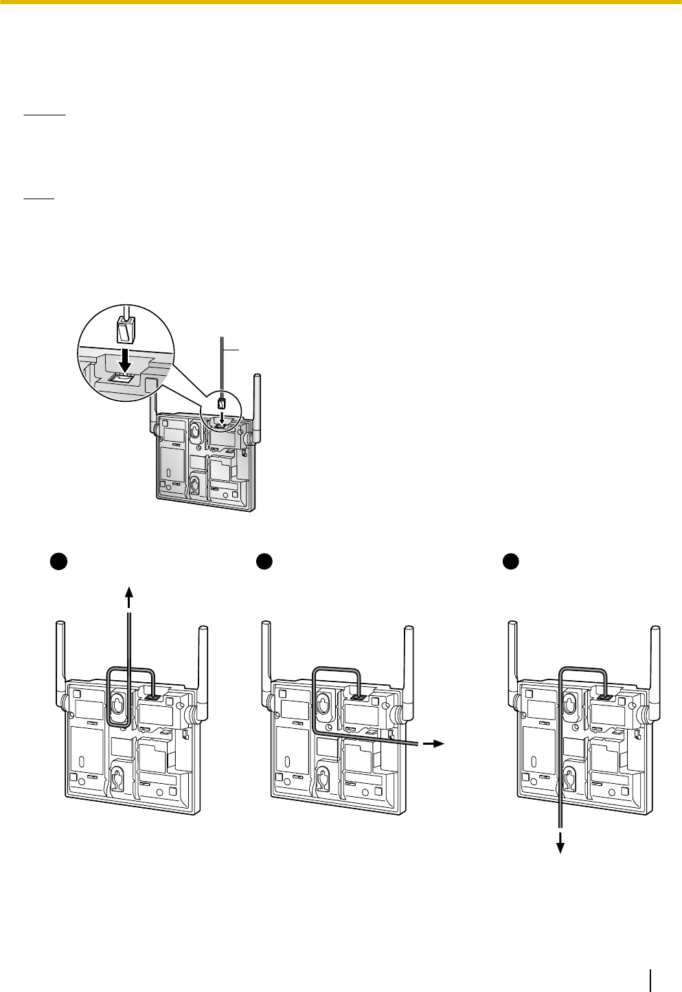
1. Connect the cable to the SIP-CS.
Ethernet Cable
2. Pass the cable through the groove of the SIP-CS in one of the following three ways.
To a Switching Hub
To a
Switching
Hub
To a Switching Hub
12 31
3. Connect the other end of the cable to the switching hub.
Installation Guide 17
3 Installing the SIP Cell Stations
Connecting an AC Adaptor to a SIP-CS
SIP-CSs comply with the IEEE 802.3af Power-over-Ethernet (PoE) standard. If PoE is available on your
network, these SIP-CSs can receive the necessary power supply from the network through the network cable.
In this case, no AC adaptor is needed for the SIP-CSs.
However, if PoE is not available, you will need to connect an AC adaptor to the SIP-CS.
WARNING
When installing or testing a SIP-CS with an external AC adaptor, the AC adaptor should be plugged
into a wall outlet or floor-mounted AC outlet. Do not connect the AC adaptor to a ceiling-mounted
AC outlet, as the weight of the adaptor may cause it to become disconnected.
Note
Use only the optional AC adaptor KX-A239 (PQLV206YB) or KX-A239X (PQLV206YB) for the SIP-CS.
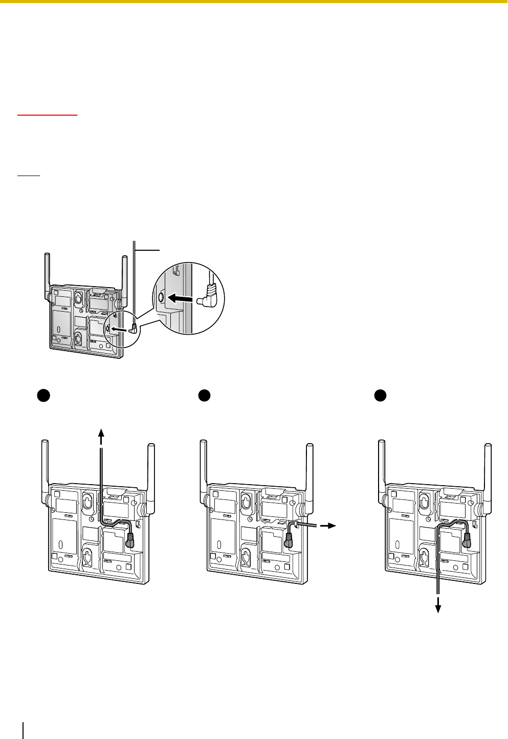
1. Connect the AC adaptor cord to the SIP-CS.
AC Adaptor Cord
2. Pass the cord through the groove of the SIP-CS in one of the following three ways.
To AC Adaptor
KX-A239
2
To AC Adaptor
KX-A239
3
To AC Adaptor
KX-A239
11
3. Connect the AC adaptor to an AC outlet.
18 Installation Guide
3 Installing the SIP Cell Stations
3.3 Wall Mounting
Mounting
WARNING
•Make sure that the wall that the CS will be attached to is strong enough to support the CS
(approx. 330 g [11.6 oz]). If not, it is necessary for the wall to be reinforced.
•Only use the wall-mounting equipment (screws, washers, wall mounting plate) included with
the CS.
•When the CS is no longer in use, make sure to detach it from the wall.
CAUTION
•When driving the screws into the wall, be careful to avoid touching any metal laths, wire laths or metal
plates in the wall.
•Do not stretch or bend the cables. Also, do not allow anything to rest on the cables.
•Use cables that are fire-resistant or fireproof.
•The CS and the cables should never be placed near or over a radiator or other heat source.
•Do not bundle cables that are connected to the CS with the AC power cords of machines located
nearby.
•Make sure the cables are securely fastened to the wall.
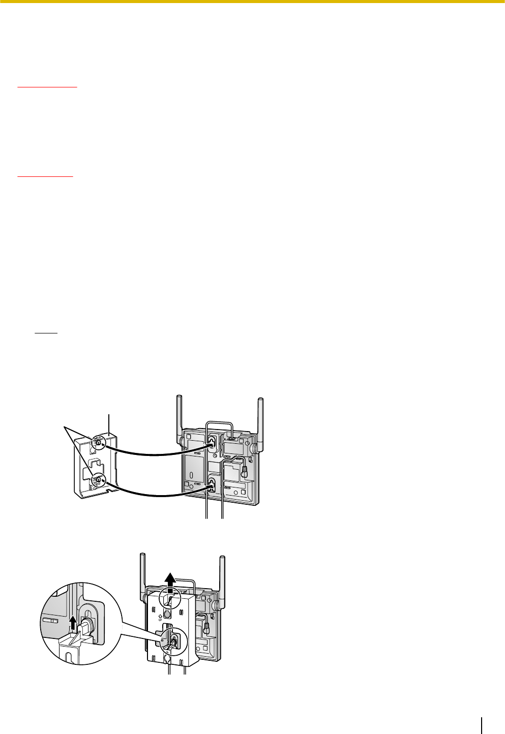
1. Place the reference for wall mounting on the wall to mark the 2 screw positions.
2. Install the 2 screws and washers (included) into the wall.
Note
•Make sure that the screw heads are at the same distance from the wall.
•Install the screws perpendicular to the wall.
3. Insert the upper and lower tabs of the wall mounting plate into the designated openings in the base unit.
Tabs
Wall Mounting Plate
(PSKL1032Y4)
4. Slide the wall mounting plate in the direction of the arrow until it clicks.
Installation Guide 19
3 Installing the SIP Cell Stations
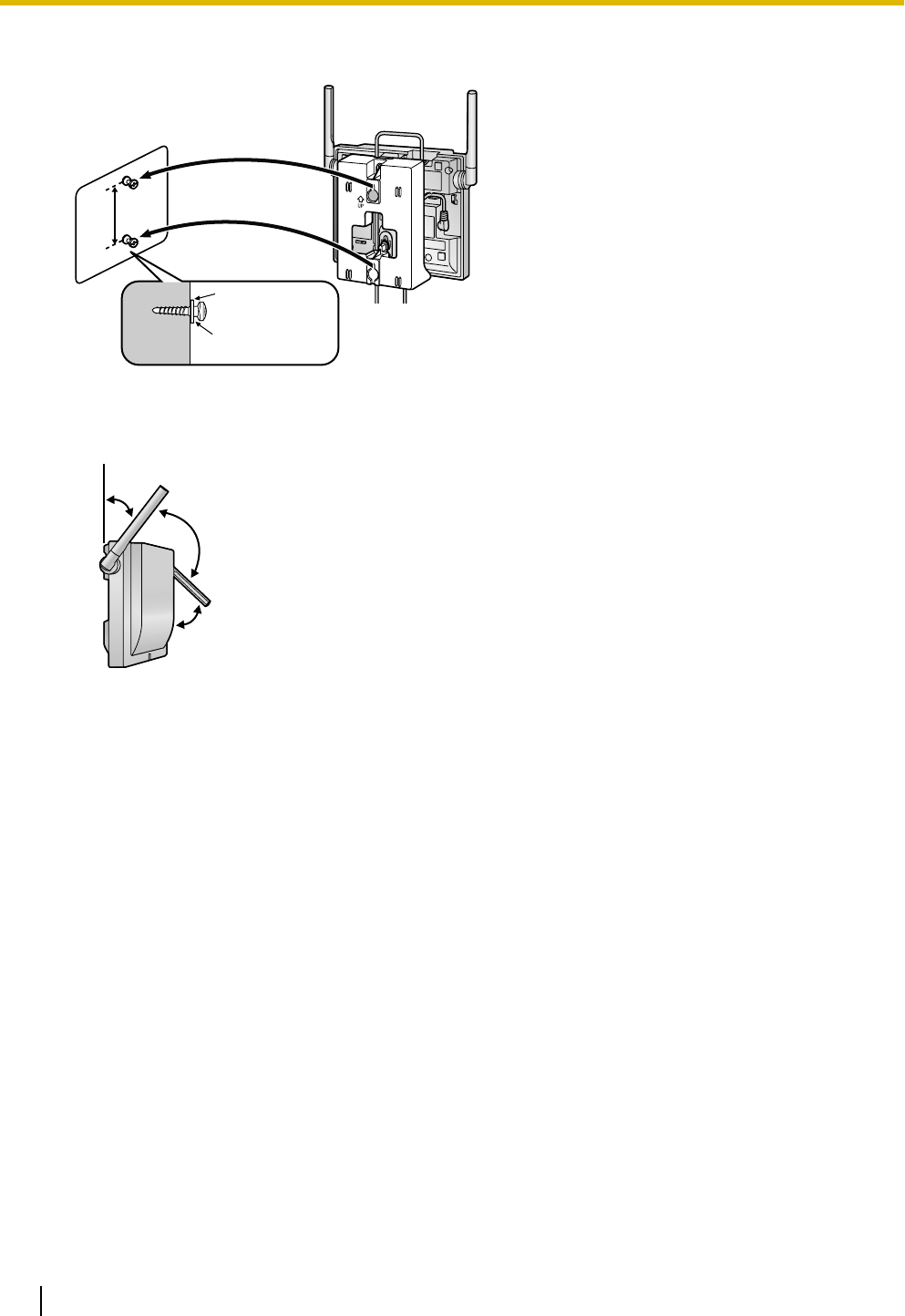
5. Hook the CS on the screw heads.
Washer
Drive the screw
to this point.
6. Place the antennas so that they are pointing in directions that are 90 degrees apart (for antenna diversity),
as follows:
45º
45º
90º
20 Installation Guide
3 Installing the SIP Cell Stations
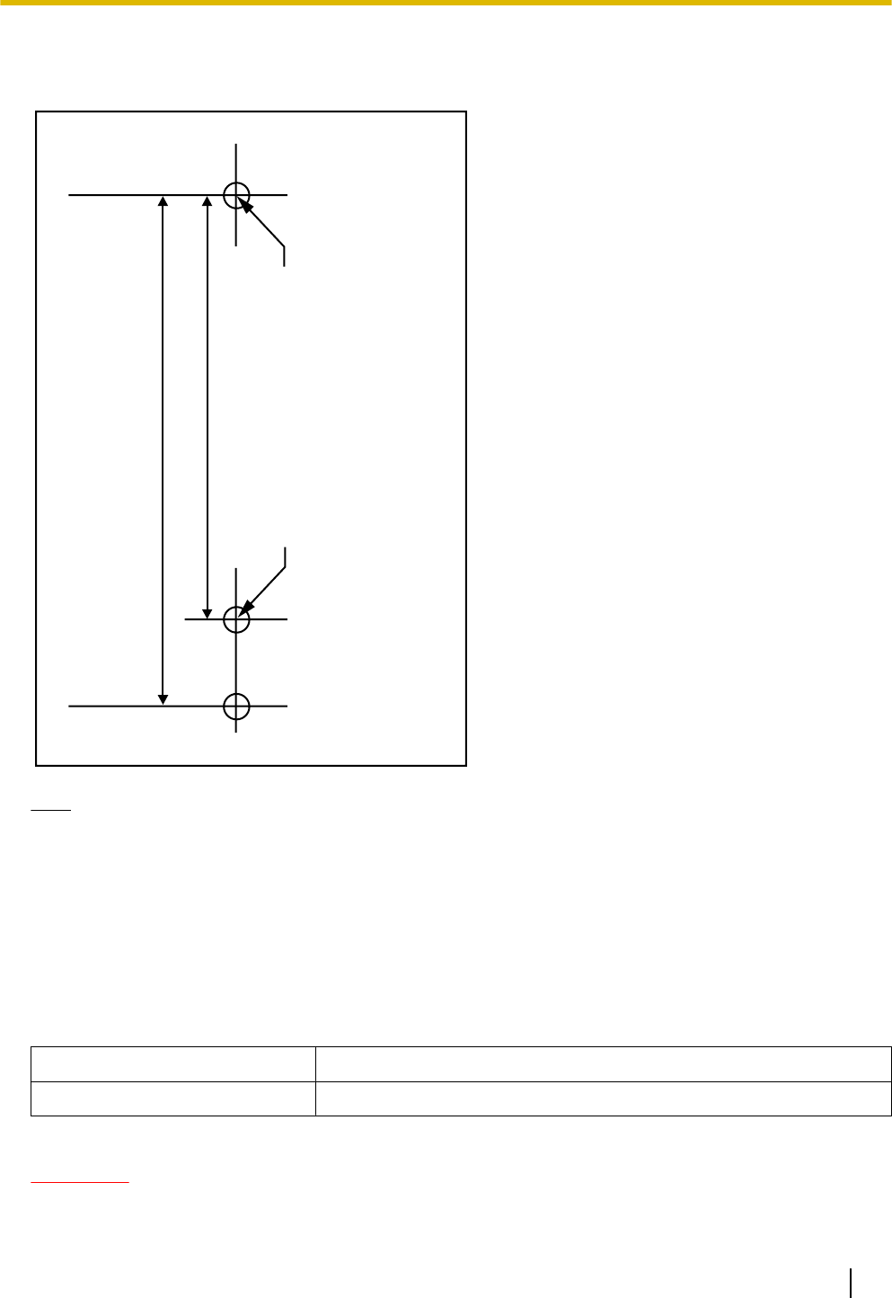
Reference for Wall Mounting
Please copy this page and use as a reference for wall mounting.
Install a screw here.
Install a screw here.
83 mm
(3-1/4 in)
100 mm
(3-15/16 in)
Note
Make sure to set the print size to correspond with the size of this page. If the dimension of the paper output
still deviates slightly from the measurement indicated here, use the measurement indicated here.
3.4 Basic Network Configuration
Configuring Network Settings for Super Master CS
Recommended Environment
The Web user interface will operate correctly in the following environments:
Operating System Microsoft® Windows® XP or Windows 7 (32 bit)
Web Browser Windows Internet Explorer® 7 or Windows Internet Explorer 8
Password Security
CAUTION
To avoid unauthorised access and possible abuse of the PBX, we strongly recommend:
Installation Guide 21
3 Installing the SIP Cell Stations
–Keeping the password secret.
–Changing your password regularly.
–Selecting a complex, random password that cannot be easily guessed.
Logging in to the Web User Interface
1. Connect a PC to the SIP-CS intended to serve as the Super Master CS.
2. Start a Web browser on the PC.
3. Enter the default IP address of the SIP-CS in the browser’s address bar.
The default IP address and subnet mask are as follows:
•IP address: 192.168.0.241
•Subnet mask: 255.255.255.0
4. Log in to the SIP-CS as the administrator.
Note
The default ID and password for the administrator are as follows:
•ID: admin
•Password: adminpass
CAUTION
For security reasons, change the administrator password after logging in to the Web user interface for the
first time.
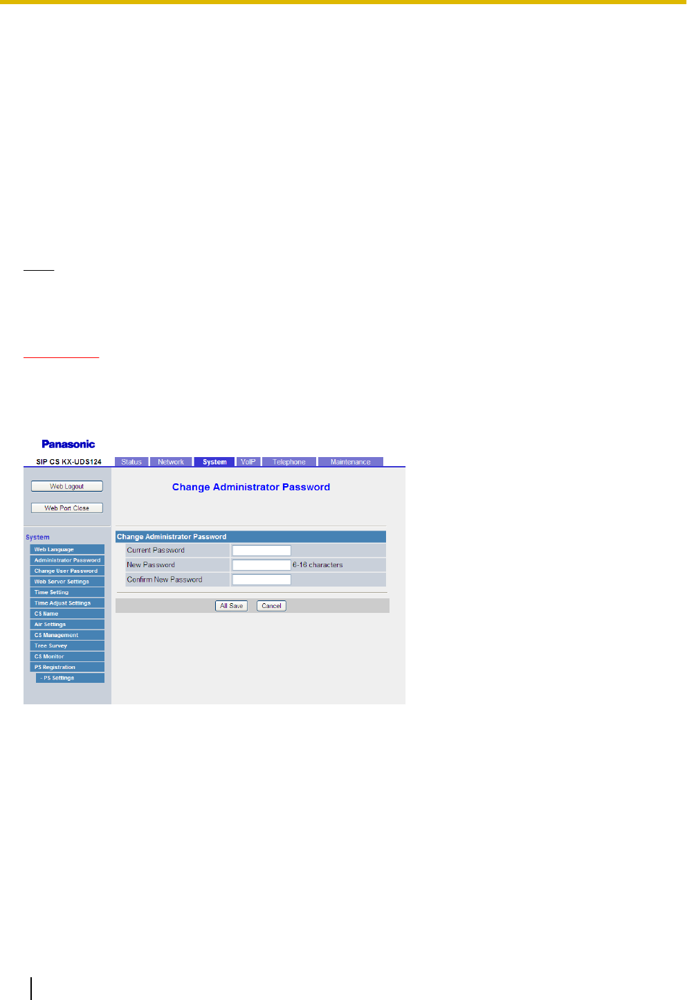
Changing the Administrator Password
1. In the System tab, select Administrator Password.
2. Enter the default password in Current Password.
3. Enter a new password in New Password.
4. Enter the new password again in Confirm New Password.
5. Click All Save.
6. In the Maintenance tab, select Restart.
7. Click Restart.
The new password will be saved and the SIP-CS will restart.
22 Installation Guide
3 Installing the SIP Cell Stations
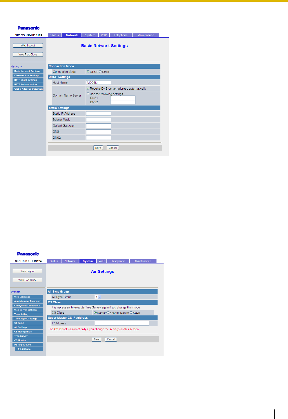
Assigning IP Address Information
255.255.255.0
192.168.0.99
The Super Master CS must have a static IP address. Follow the procedure below to configure static IP address
information.
1. In the Network tab, select Basic Network Settings.
2. Enter the IP address of the Super Master CS in Static IP Address.
3. Enter the subnet mask in Subnet Mask.
4. Enter the IP address of the default gateway in Default Gateway.
5. Enter the IP address of the primary DNS server in DNS1.
6. Enter the IP address of an secondary DNS server in DNS2.
7. Click Save.
Configuring Air Synchronisation Settings
Follow the procedure below to change the SIP-CS status to Master.
1. In the System tab, select Air Settings.
2. In CS Class, select Master.
3. Enter the IP address of the Super Master CS in IP Address.
Installation Guide 23
3 Installing the SIP Cell Stations

4. Click Save.
The SIP-CS will restart.
The SIP-CS is now set as the Super Master CS.
Connecting SIP-CSs to the LAN
Confirming the MAC Addresses of all the SIP-CSs
Before connecting the SIP-CSs to the LAN, confirm the MAC address of each SIP-CS.
The MAC address of each SIP-CS is required in a procedure described later. The MAC address is written on
the rear side of each SIP-CS.
Connecting SIP-CSs to the LAN
1. Disconnect the Super Master CS from the PC.
2. Place the Super Master CS in its planned location, and then connect it to the LAN.
3. Place the other SIP-CSs in their planned locations, and then connect them to the LAN.
All the SIP-CSs (except Super Master CS) will automatically acquire their IP address from the DHCP server.
24 Installation Guide
3 Installing the SIP Cell Stations

4 Deployment Procedure
The deployment procedure for establishing a wireless system is as follows.
4.1 Overview
1. Site Planning
Choose the optimal installation locations for SIP-CSs. Site planning requires careful preparation and thorough
testing.
2. Site Survey
Confirm the signal condition of the planned location using two un-registered CSs and one S-PS.
When connecting the wireless system, use extreme care in conducting the site survey. Site surveys can be
conducted using two KX-UDS124s. An incorrectly performed site survey can result in a poor service area,
frequent noise, disconnection of calls, and synchronisation failure of SIP-CSs.
3. CS Registration
Register all SIP-CSs in the system which the Air Sync Master CS is controlling.
4. Tree Survey
Create the synchronisation hierarchy for each Air Sync Group to provide stable Air Synchronisation.
There are 2 types of Tree Survey methods, as shown in the table below:
Tree Survey Type Description References
Web User Interface
Programming
Installing the SIP-CS after conducting a
Tree Survey by accessing the Web user
interface from a PC connected to the same
network.
This method provides an easier but less
accurate Tree Survey.
Refer to "Section 2 Web User
Interface Programming" in the
Administrator Guide.
CS Maintenance
Tool Programming
Installing the SIP-CS after conducting a
Tree Survey using the CS Maintenance
Tool installed on a PC connected to the
same network.
This method provides a more accurate
Tree Survey.
xxx
5. Configuration
Specify SIP server network informations, and SIP account information of extensions.
6. S-PS Registration
Register S-PSs to the Super Master CS.
Installation Guide 25
4 Deployment Procedure

7. S-PSs Area Check
Check the service area, sound quality, and handover operation under actual conditions.
26 Installation Guide
4 Deployment Procedure
4.2 Site Planning
In order to be able to move between coverage areas during a call (Handover), synchronisation between
SIP-CSs is necessary. If synchronisation between SIP-CSs has not been configured, handover will fail. The
source of synchronisation is called a Master CS and the target of synchronisation is called a Slave CS. An Air
Synchronisation Group is created with the Master/Slave CSs on different levels. The source of synchronisation
for each SIP-CS in an Air Synchronisation Group is called an Air Synchronisation Master CS.
The number of Master/Slave levels in an Air Synchronisation Group cannot exceed 8. To ensure that the
number of levels does not exceed 8, locate the Air Synchronisation Master CS in the centre of the group. A
greater number of levels can lead to instability in handover and Air Synchronisation.
The Master CS of Air Synchronisation Group 1 is called the Super Master CS and controls the whole system.
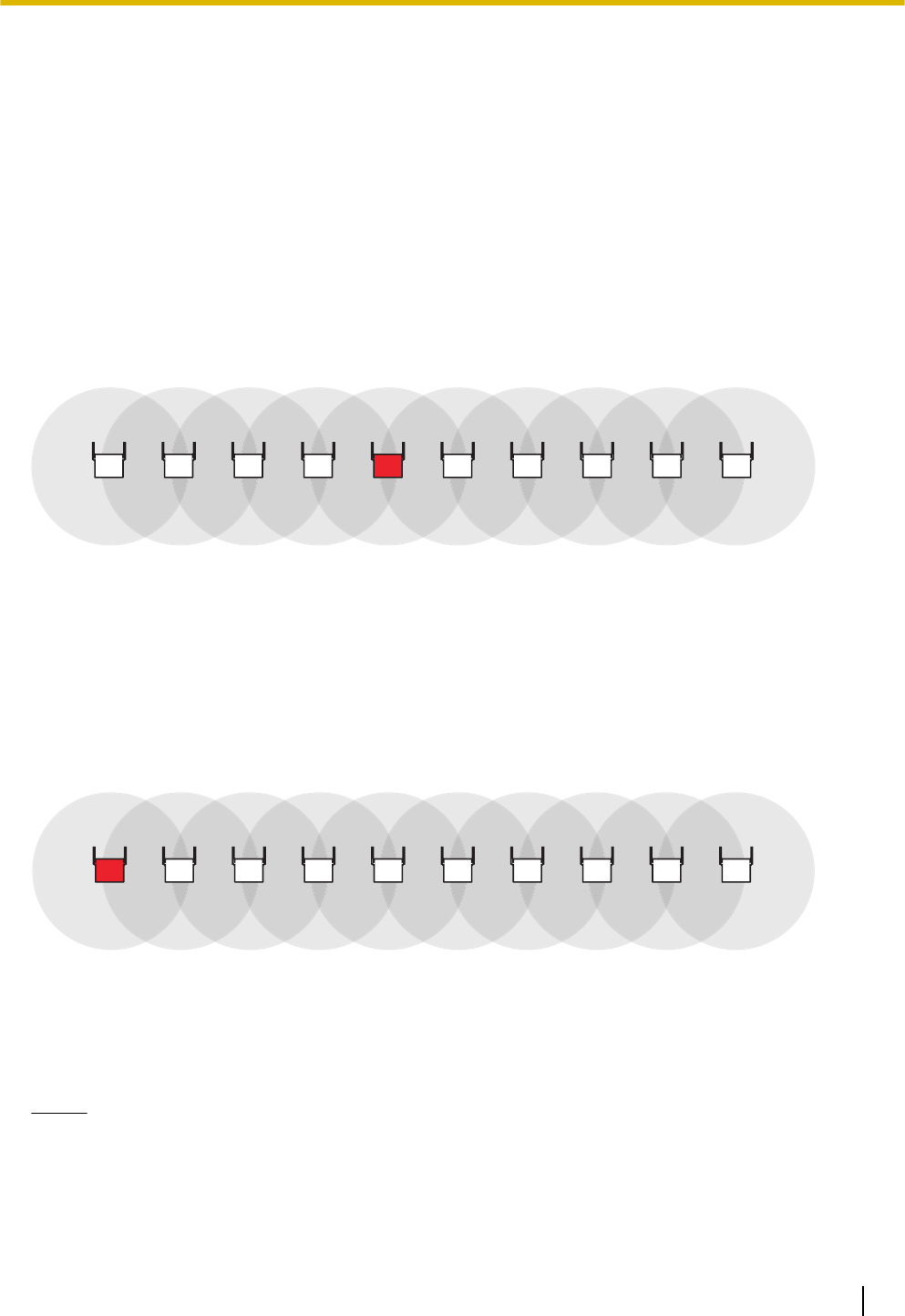
Good Example:
The Master CS is located in the centre of the installation site for each Air Sync Group.
1 98765432 10
Number of Master/Slave level: 5
Bad Example:
The Master CS is NOT located in the centre of the installation site for each Air Sync Group. Therefore, the
number of layers in the hierarchy exceeds 8.
1 98765432 10
Number of Master/Slave level: 10
Notice
•Choosing the best site for the SIP-CS requires careful planning and testing. The best location may not
always be convenient for installation.
•It is necessary to locate SIP-CSs within synchronisation range of other SIP-CSs, however, locating
SIP-CSs too close to each other can lead to interference and a reduction in the number of simultaneous
calls. In a regular office, the average distance between SIP-CSs should be approximately 30 m.
Installation Guide 27
4 Deployment Procedure
However, since walls, metallic shelves, etc. can weaken signals, Air Synchronisation may not be as
stable as planned. Conduct a site survey after installing the SIP-CSs, as described in the next chapter.
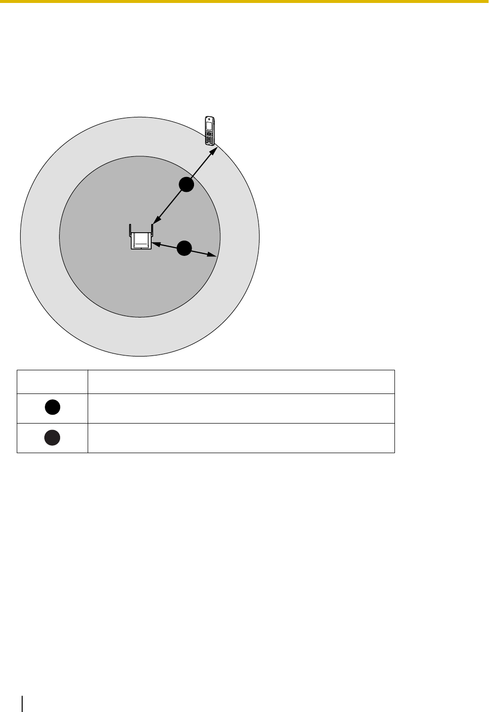
CS Coverage Area for Establishing Conversations
The example below shows the size of the area where one SIP-CS can provide service for S-PSs, if it is installed
in an area with no obstacles.
A
B
Area Description
A
Air Synchronisation coverage area
(Radius: About 1 m to 40 m)
B
S-PS coverage area
(Radius: About 1 m to 50 m)
Understanding Radio Waves
Characteristics of Radio Waves
The transmission of radio waves and the SIP-CS coverage area depend on the structure and materials of the
building.
Office equipment, such as computers and fax machines, can interfere with radio waves. Such equipment may
create noise or interfere with the performance of the S-PS.
The illustration below shows the special transmitting patterns of radio waves.
1. Radio waves are reflected by objects made of materials such as metal.
2. Radio waves are diffracted by objects such as metallic columns.
28 Installation Guide
4 Deployment Procedure
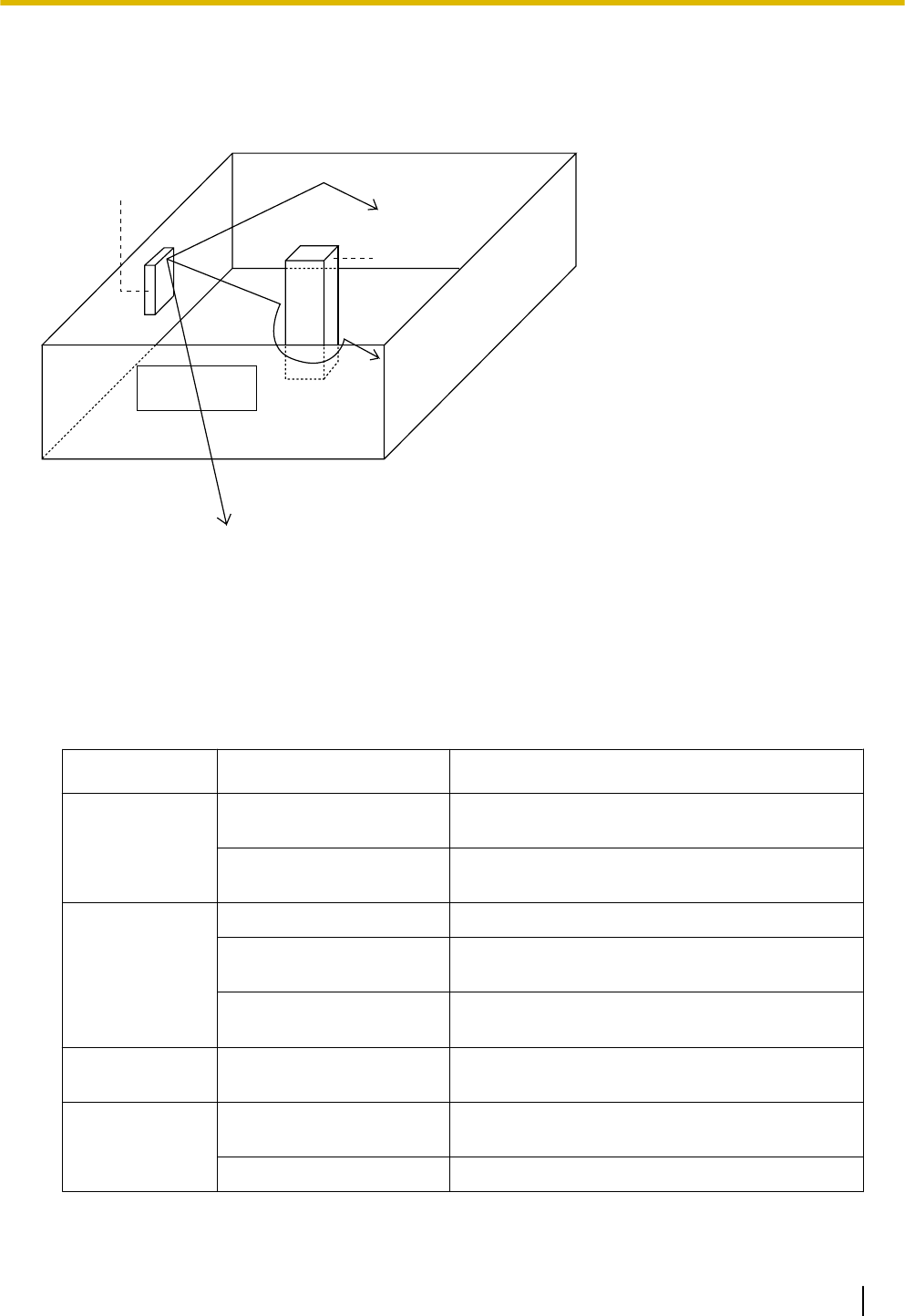
3. Radio waves penetrate objects made of materials such as glass.
SIP-CS
Column
3. Penetration
2. Diffraction
1. Reflection
Relationships Between Radio Waves and Building Structure and Materials
•The SIP-CS coverage area is affected more by the building materials and their thickness than the number
of obstacles.
•Radio waves tend to be reflected or diffracted by conductive objects and rarely penetrate them.
•Radio waves tend to penetrate insulated objects and are rarely reflected by them.
•Radio waves penetrate thin objects more than thick objects.
•The table below shows the transmission tendency of radio waves when they reach objects made from
various materials.
Object Material Transmission Tendency
Wall Concrete The thicker they are, the less radio waves
penetrate them.
Ferroconcrete Radio waves can penetrate them, but the more
iron there is, the more radio waves are reflected.
Window Glass Radio waves usually penetrate them.
Glass with wire net Radio waves can penetrate them, but tend to be
reflected.
Glass covered with
heat-resistant film
Radio waves are weakened considerably when
they penetrate windows.
Floor Ferroconcrete Radio waves can penetrate them, but the more
iron there is, the more radio waves are reflected.
Partition Steel Radio waves are reflected and rarely penetrate
them.
Plywood, Glass Radio waves usually penetrate them.
Installation Guide 29
4 Deployment Procedure
Object Material Transmission Tendency
Column Ferroconcrete Radio waves can penetrate them, but the more
iron there is, the more radio waves tend to be
reflected or diffracted.
Metal Radio waves tend to be reflected or diffracted.
Cabinet Steel Radio waves are usually reflected or diffracted,
and rarely penetrate them.
Wood Radio waves can penetrate them, but they are
weakened.
General Installation
Obtain a map of the SIP-CS installation site, identify the service area required by the user on the map, and
then plan the location of each SIP-CS.
It is recommended that you install the SIP-CS at a height of 2 m of more for less obstructions.
Follow the procedure below to perform site planning for general installation:
1. Decide where to install the first SIP-CS.
2. Install the second SIP-CS at a distance of about 30 m from the first SIP-CS. If you cannot maintain a
distance of 30 m due to building limitations, install the second SIP-CS as far away as possible in the
overlapping range of the Air Synchronisation coverage area.
Notice
Locate SIP-CSs so that places where most calls will be made are within the coverage area of as many
SIP-CSs as possible.
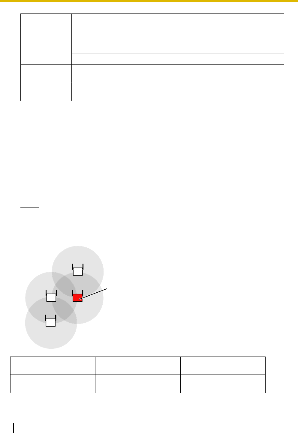
3. When you have covered the necessary area, make the SIP-CS that is adjacent to most other SIP-CSs into
the Air Sync Master CS.
Air Sync Master CS
SIP-CS(1)
SIP-CS(2)SIP-CS(3)
SIP-CS(4)
SIP-CS Overlapping Coverage Area Other SIP-CSs in the
Coverage Area
SIP-CS(1) SIP-CS(2)
SIP-CS(3)
SIP-CS(2)
30 Installation Guide
4 Deployment Procedure
SIP-CS Overlapping Coverage Area Other SIP-CSs in the
Coverage Area
SIP-CS(2)
SIP-CS(1)
SIP-CS(3)
SIP-CS(4)
SIP-CS(1)
SIP-CS(3)
SIP-CS(3)
SIP-CS(1)
SIP-CS(2)
SIP-CS(4)
SIP-CS(2)
SIP-CS(4)
SIP-CS(4) SIP-CS(2)
SIP-CS(3)
SIP-CS(3)
SIP-CS(2) and SIP-CS(3) are adjacent to most other SIP-CSs.
Therefore, in this case choose SIP-CS(2) or SIP-CS(3) as the Air Sync Master CS.
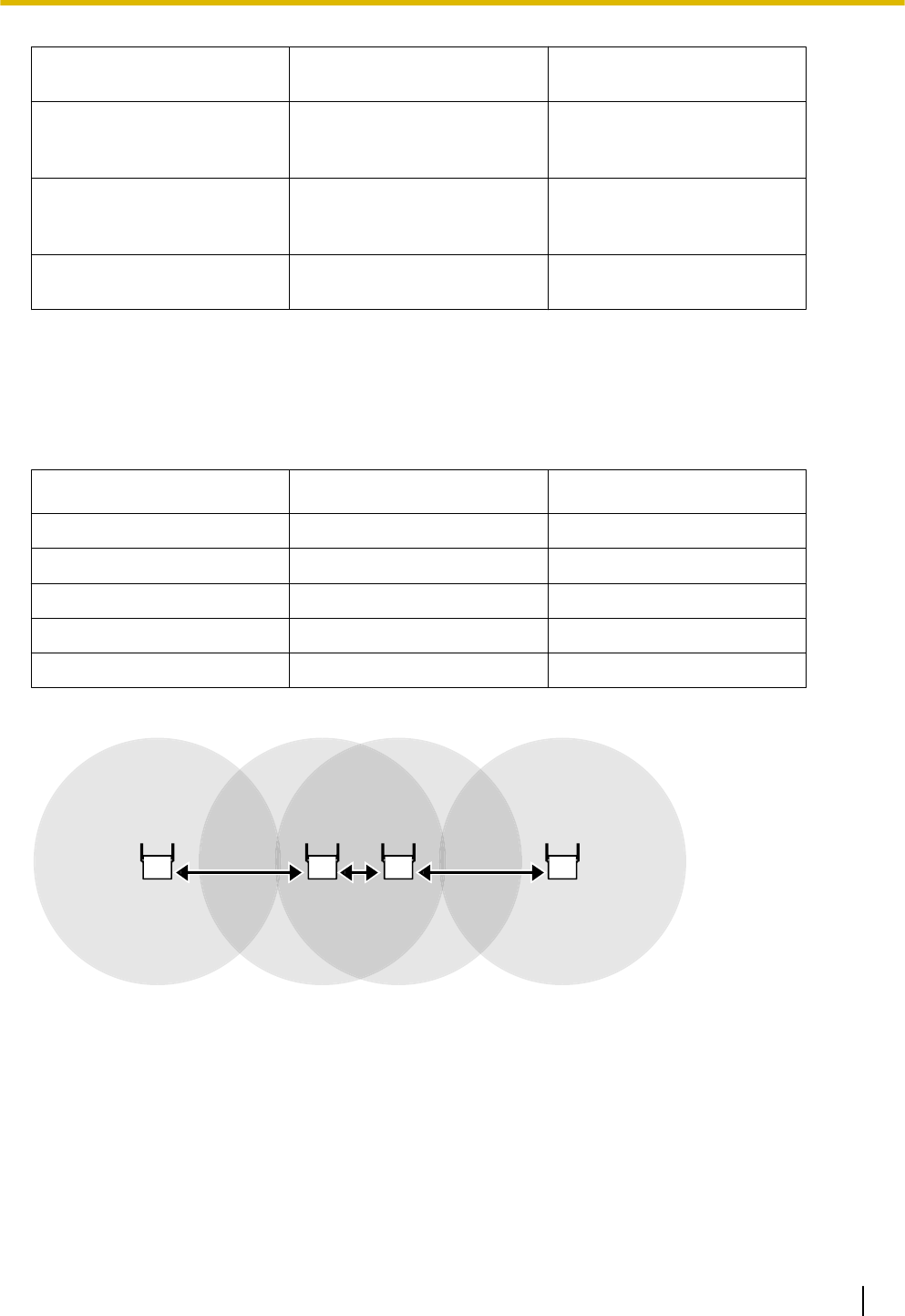
Adjoining Installation
When you want to make many simultaneous calls in a small area, locate SIP-CSs according to the table below.
Simultaneous Calls Number of CSs Distance between CSs
Up to 4 1 -
5 to 8 2 1 m
9 to 12 3 10 m
13 to 16 4 10 m
More than 17 Not Recommended Not Recommended
Example 1
1 m 30 m
30 m
Installation Guide 31
4 Deployment Procedure
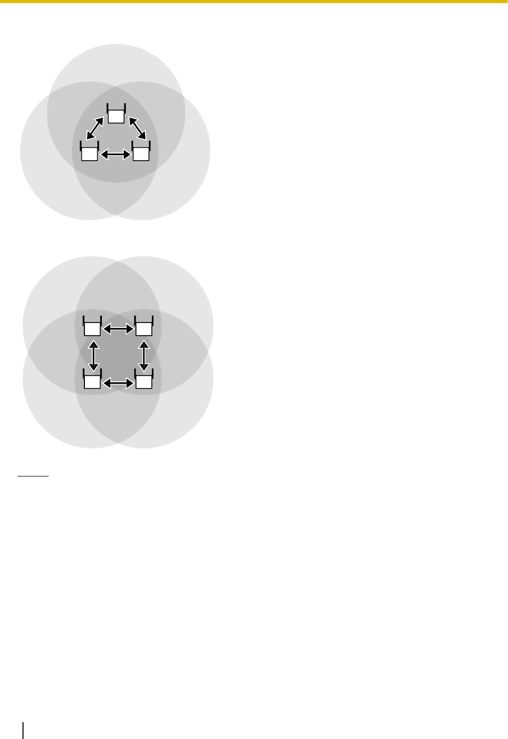
Example 2 (Vertical)
10 m 10 m
10 m
Example 3 (Vertical)
10 m
10 m 10 m
10 m
Notice
•It may not be possible to create an Air Sync Group that spans multiple floors, because the dividing
ceilings may weaken the signal too much. In this case, locate a connecting SIP-CS in the staircase
between each floor.
•When creating an Air Sync Group that spans multiple floors, make sure that you conduct a site survey
on each floor.
•Make the SIP-CS that is adjacent to most other SIP-CSs (in all 3 dimensions) into the Master CS.
Air Synchronisation
Air synchronisation assigns classifications to SIP-CS and establishes connections based on those
classifications. This creates a robust system where the whole system is not reliant upon one SIP-CS.
32 Installation Guide
4 Deployment Procedure
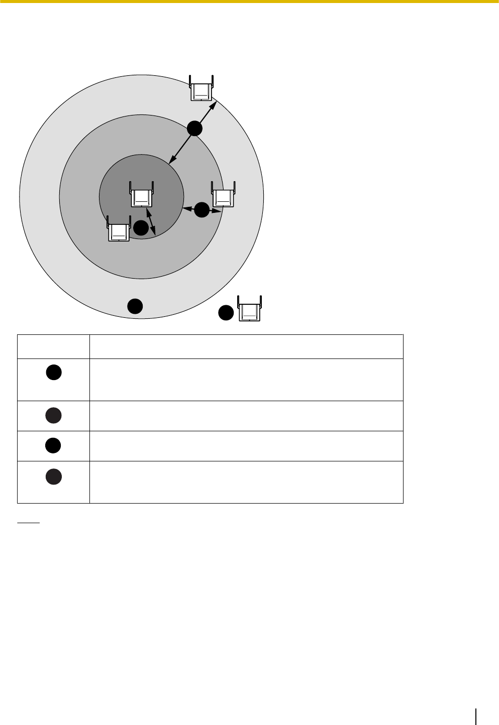
CS Coverage Area for Air Synchronisation between SIP-CSs
The example below shows the size of the area where one SIP-CS can synchronise with other SIP-CSs, if it is
installed in an area with no obstacles.
D
D
C
B
A
Area Description
A
Good Coverage Area:
Radio signal strength level is "Good" (20 m to 40 m).
Good synchronisation quality can be maintained.
B
Coverage Area
Radio signal strength level is "Bad" (about 20 m to 50 m).
C
Grey Zone:
Conversation will be intermittent.
D
Out of Service:
Too close (0 m to 1 m) or too far so that the radio signal is lost and
the SIP-CSs cannot be synchronised.
Note
For air synchronisation radio signal strength details, refer to "Site Survey Mode" in "LED Indications" table
found in "2 Overview".
Installation Guide 33
4 Deployment Procedure
4.3 Site Survey
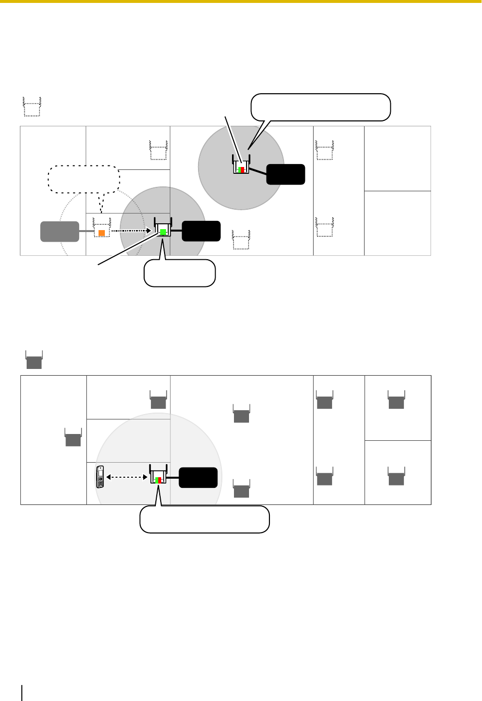
Confirming SIP-CS Coverage Area for Air Synchronisation between SIP-CSs
Confirm the radio signal strength of the SIP-CS at each planned location. The SIP-CS’s LED indicates the
strength of the wireless connection.
: Planned Location
AC
adaptor
AC
adaptor
AC
adaptor
Site Survey
Master Mode
Site Survey
Slave Mode
LED:
Orange flashing
LED:
Green flashing
LED:
Red and green alternate flashing
Confirming SIP-CS Coverage Area for Establishing Conversations
After confirming the SIP-CS coverage area for air synchronisation, confirm the speech quality. The speech
quality will be shown on the S-PS’s LCD.
AC
Adaptor
: Confirmed Location
LED:
Red and green alternate flashing
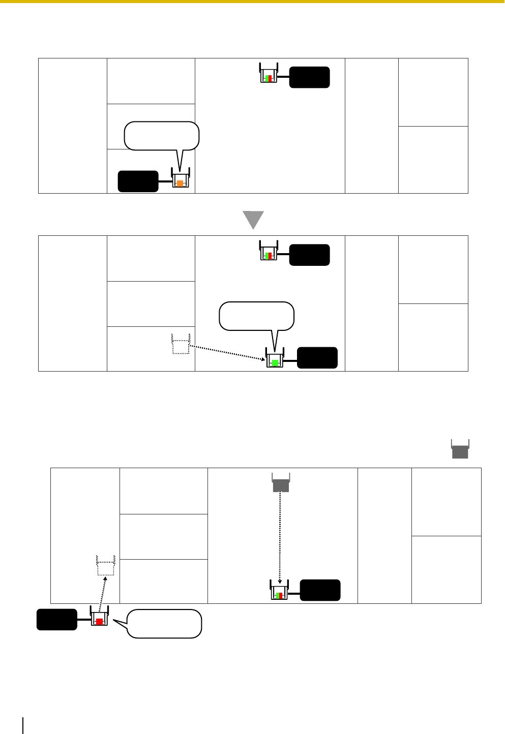
Site Survey for Air Synchronisation
After completing site planning, you can use 2 SIP-CSs to conduct the site survey to check radio signal strength.
Then, if necessary, modify the location of the SIP-CSs accordingly. You can check the radio signal strength
by the colour of the SIP-CS’s LED.
Confirming the Coverage Area for Air Synchronisation between SIP-CSs
1. Supply power to the 2 SIP-CSs using AC adaptors.
2. Turn on SIP-CS(1) by holding the RESET switch.
34 Installation Guide
4 Deployment Procedure
3. Once SIP-CS(1) turns on, release the RESET switch, and then press the RESET switch again.
SIP-CS(1) will enter Site Survey Master mode.
4. Turn on SIP-CS(2) normally. SIP-CS(2) will enter Site Survey Slave mode automatically when it receives
a signal from SIP-CS(1).
5. Place SIP-CS(1) where the Air Sync Master CS is planned to be located.
Planned Location for
Air Sync Master CS
AC
adaptor Planned Location:
SIP-CS(1)
(Site Survey
Master Mode)
LED:
Red and green alternate flashing
6. Place SIP-CS(2) in the location planned for the SIP-CS closest to the Air Sync Master CS (currently
SIP-CS[1]).
AC
adaptor
AC
adaptor
SIP-CS(1)
SIP-CS(2)
(Site Survey
Slave Mode)
LED:
Red flashing
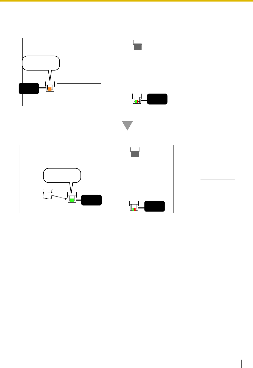
7. Confirm whether the LED of SIP-CS(2) is green.
If it is not green, move SIP-CS(2) around to find a location where its LED turns green.
Note
•The LED indicates radio signal strength levels for air synchronisation. For details, refer to "CS
Coverage Area for Establishing Conversations" in "4.2 Site Planning".
Installation Guide 35
4 Deployment Procedure
•For more details about the LED indications of the SIP-CS when in Site Survey mode, refer to "LED
Indications" in "3 Installing the SIP Cell Stations".
AC
adaptor
AC
adaptor
SIP-CS(1)
SIP-CS(2)
AC
adaptor
SIP-CS(1)
SIP-CS(2)
AC
adaptor
LED:
Orange flashing
LED:
Green flashing
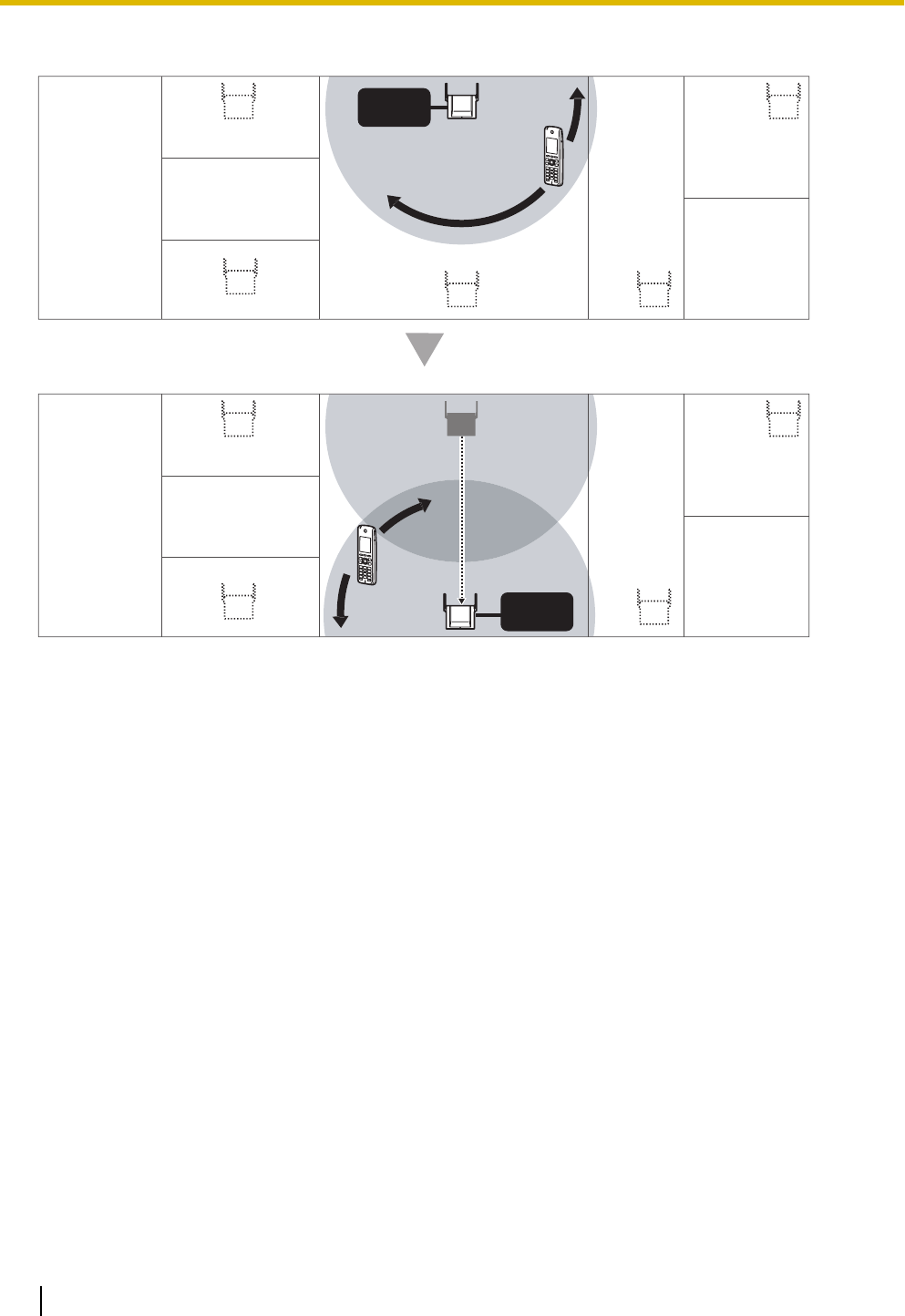
8. Place SIP-CS(1) where SIP-CS(2) was, and then place SIP-CS(2) in the location planned for the SIP-CS
closest to current location of SIP-CS(1).
AC
adaptor
SIP-CS(1)
SIP-CS(2)
AC
adaptor
Confirmed Location:
LED:
Red flashing
36 Installation Guide
4 Deployment Procedure
9. Confirm whether the LED of SIP-CS(2) is green. If it is not green, move SIP-CS(2) around to find a location
where its LED turns green.
AC
adaptor SIP-CS(1)
AC
adaptor
SIP-CS(1)
AC
adaptor
AC
adaptor
SIP-CS(2)
LED:
Orange flashing
SIP-CS(2)
LED:
Green flashing
10. Repeat steps 8 to 9 for all other locations.
Installation Guide 37
4 Deployment Procedure
Site Survey for S-PS Service Area
Each S-PS has a CS Area Check mode that monitors the state of the radio link to the SIP-CS to check the
S-PS service area for establishing conversations. In CS Area Check mode, the following are displayed on the
S-PS with a refresh interval of 2 seconds: the SIP-CS ID of the SIP-CS to which the S-PS is connected, the
radio strength level, and the Error Rate. For each confirmed SIP-CS location, set the S-PS to CS Area Check
mode, and then place a SIP-CS at that location to measure the coverage area. Then, record the results on the
map of the installation site. This site survey requires 1 S-PS and 1 SIP-CS.
Notice
Conduct the site survey starting with the confirmed location for Air Sync Master CS, and then go to closest
location next.
Before Site Survey for S-PS Service Area
Checking the SIP-CS ID Number
Check the SIP-CS ID number label attached to the SIP-CS.
The SIP-CS ID number is attached to the rear side of the SIP-CS.
Starting the S-PS in Maintenance Mode
The S-PS must be in Maintenance mode to conduct a site survey.
To enter Maintenance mode, follow the procedure below:
Note
Before using an S-PS, the battery must be inserted and then charged for the specified amount of time. For
details, refer to the documentation for the S-PS.
1. The S-PS should be in a powered off state. If the S-PS is turned on, turn it off by pressing and holding the
POWER/CANCEL key.
2. Turn on the S-PS by pressing and holding the POWER/CANCEL key.
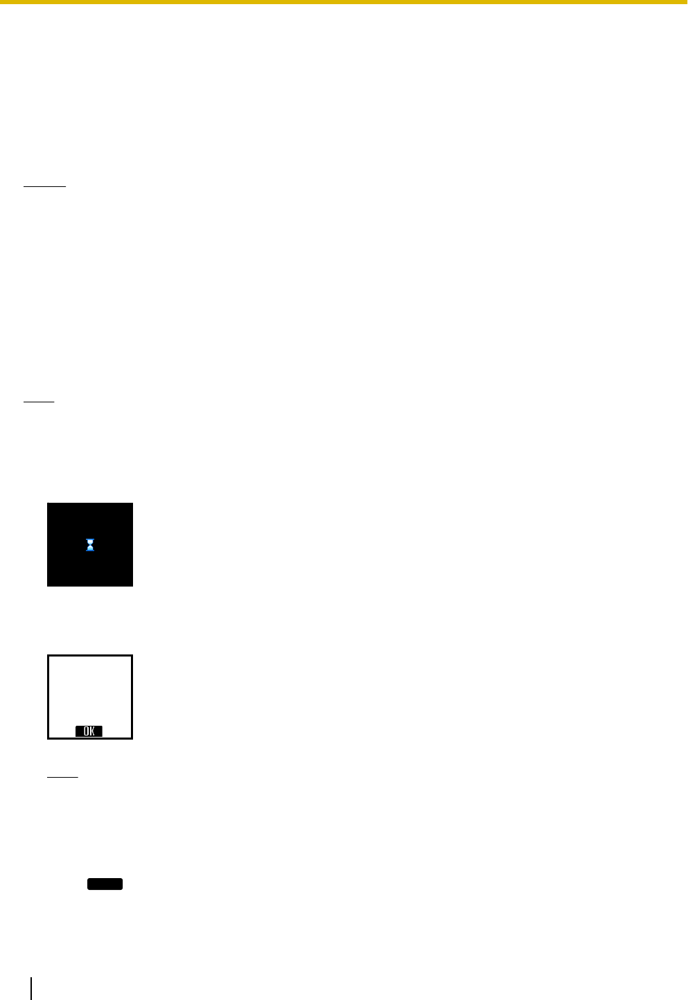
3. After turning on the S-PS, a blank screen will be displayed. At this time, press and hold the TALK/
SP-PHONE key for about 7 seconds, and then release the key.
The S-PS will start in Maintenance mode.
Maintenace Mode
Ver.01.00
Note
When it takes more than 7 seconds to start Maintenance mode, follow the procedure below to return
stand by screen:
a. Press the left soft key.
b. Press [8] ® [1].
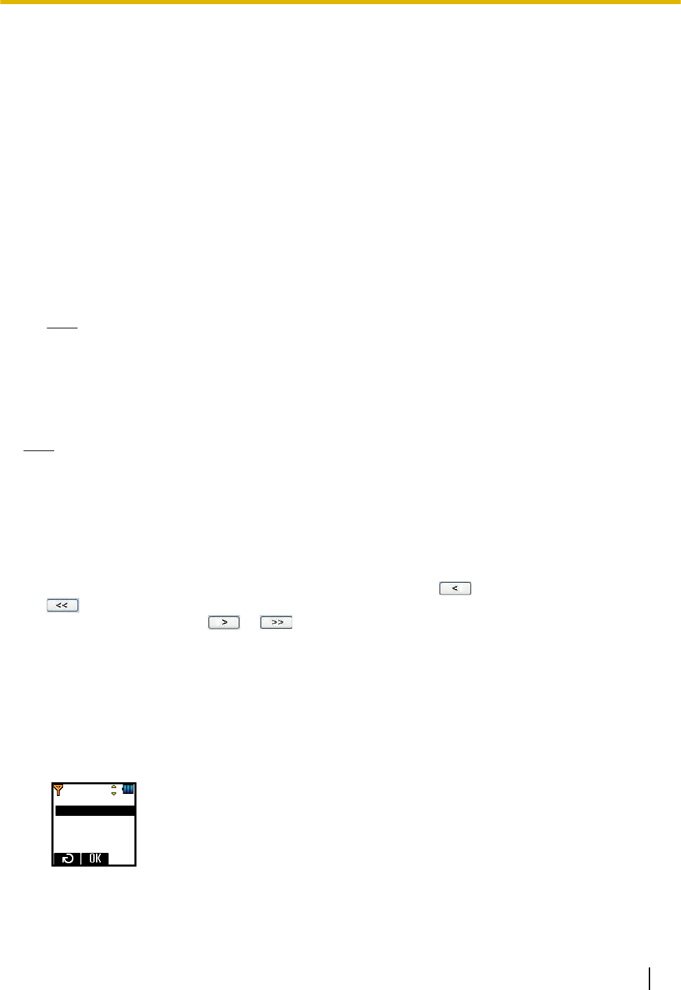
The Maintenance mode main menu will be displayed.
4. Press
OK
.
38 Installation Guide
4 Deployment Procedure
The Maintenance mode main menu will be displayed.
No Service Alarm
CS Monitor
Reset Handset
Full Charge LED
Side Tone Vol
Site Survey for S-PS Service Area
1. Place a SIP-CS in the location confirmed for the Air Sync Master CS in the previous site survey.
2. Supply power to the SIP-CS using an AC adaptor.
3. Start the S-PS in Maintenance mode.
(See "Starting the S-PS in Maintenance Mode", above.)
4. Select "CS Area Check" on the S-PS.
5. Press
OK
twice.
The S-PS will be in CS Area Check mode and you will hear a tone.
6. Walk around the SIP-CS to confirm the SIP-CS’s service area.
If the radio strength level and Error Rate are at acceptable levels, you will continue hearing a tone from
the S-PS and 2 lines on the LCD of the S-PS light green.
Note
If there is an area where you cannot hear a tone and the 2 lines of the LCD do not light green, relocate
the SIP-CS.
7. After confirming the service area, press TALK/SP-PHONE key on the S-PS to stop the tone.
8. Relocate the SIP-CS to another location.
9. Walk around the SIP-CS to confirm the SIP-CS’s service area.
10. Repeat steps 8 to 9 for all the locations so that the SIP-CSs will provide service for whole area.
Installation Guide 39
4 Deployment Procedure
Example:
AC
adaptor
AC
adaptor
40 Installation Guide
4 Deployment Procedure
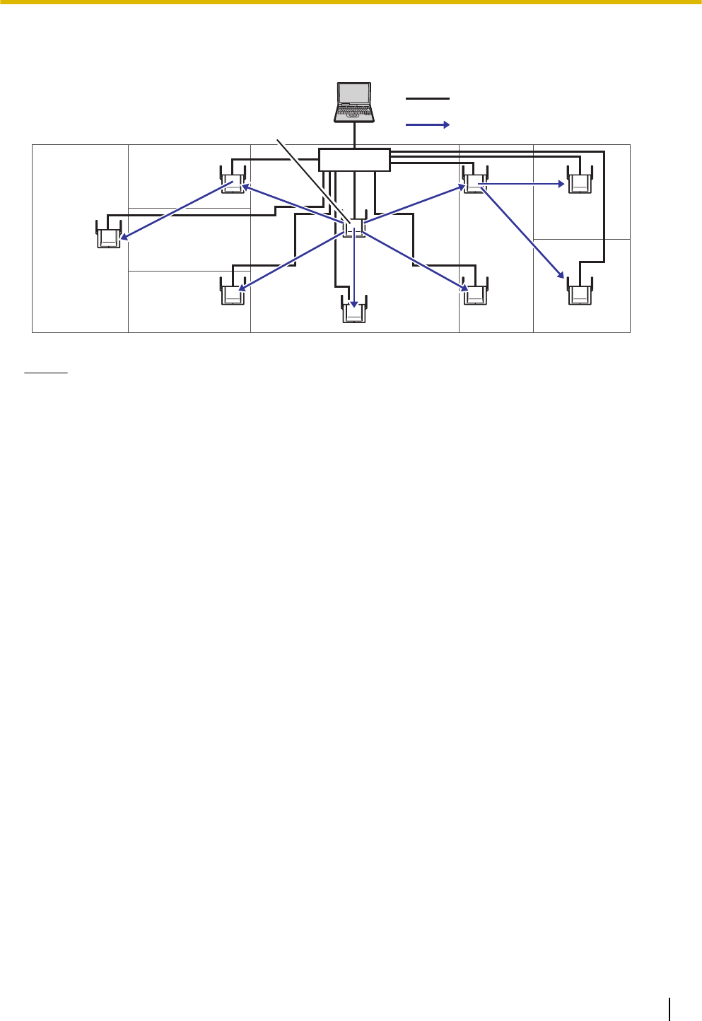
4.4 CS Registration
PoE Hub
Master CS
(Site Survey Mode)
: Ethernet Cable
: Air Synchronisation
Notice
•Connect each SIP-CS in the Air Sync Group to the network and turn them on.
•During CS Registration, make sure that all unregistered SIP-CSs that are not in the Air Sync Group
you are registering are turned off.
Confirming the MAC address of a SIP-CS
To register SIP-CSs to the Air Sync Master CS, the MAC address of each SIP-CS is required.
The MAC address is written on the rear side of each SIP-CS. Confirm the MAC address of each SIP-CS before
registering it.
Before registering
For the Super Master CS
Provide a static IP address which can be used on your network.
For details, refer to "Assigning IP Address Information" in "3.4 Basic Network Configuration".
For Air Sync Master CSs other than Super Master CS
Set the IP address of the Super Master CS.
In Pre Sync procedure, all the SIP-CSs in Site Survey mode will be registered to the Air Sync Master CS.
Confirm that all the LEDs of the SIP-CSs are green. If any LED is not green, revise the location of the SIP-CSs.
Installation Guide 41
4 Deployment Procedure
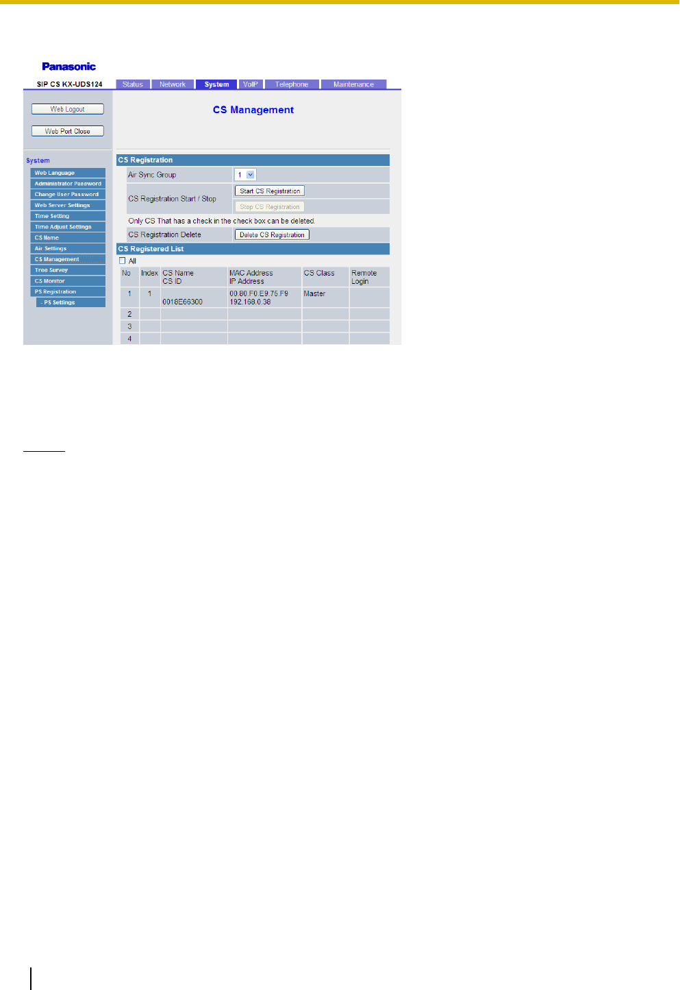
Registering SIP-CSs to the Super Master CS
1. In the System tab, select CS Management.
2. Select Air Sync Group.
3. Click Start CS Registration.
All the SIP-CSs on the LAN will be registered, and then displayed in CS Registered List.
Notice
You cannot register the following SIP-CSs:
•SIP-CSs that are not turned on
•SIP-CSs that are not connected to the network
•SIP-CSs for which no IP address has been set
•SIP-CSs that cannot receive radio signals
42 Installation Guide
4 Deployment Procedure
4.5 Tree Survey
The Tree Survey creates the most suitable synchronisation tree automatically for SIP-CSs. You also can
configure Air Sync Groups in this procedure.
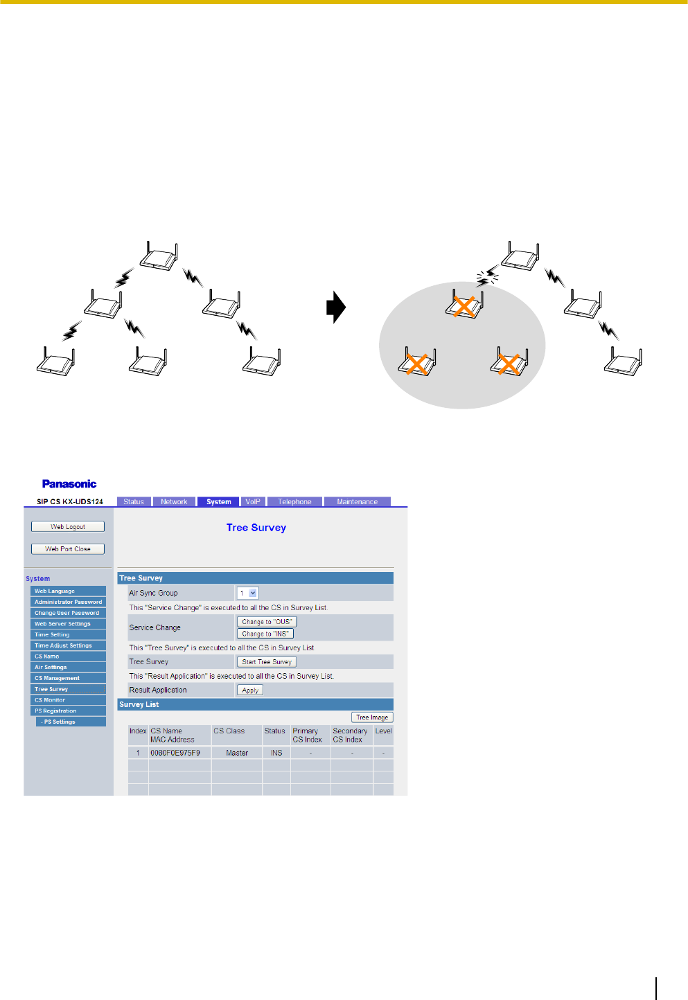
The Tree Survey creates a Master/Slave tree structure with the Air Sync Master CS at the top and with stable
air synchronisation. The procedure can be performed automatically by using either the Web user interface or
the CS maintenance tool. The Tree Survey not only specifies the level for each SIP-CS, but also a primary and
secondary synchronising CS from which the SIP-CS will receive its clock signal. The secondary synchronising
CS is used as a backup so that if the primary synchronising CS fails the whole system will not be affected.
Air Sync Master CS
(Master Clock Signal)
Master CS
Slave CS Slave CS
Air Sync Master CS
(Master Clock Signal)
Master CS
Slave CS Slave CS
Radio Link Loss
SIP-CSs stop working
Preparing for Tree Survey
Follow the procedure below to put the SIP-CSs in Tree Survey mode.
1. In the System tab, select Tree Survey.
2. Confirm that all SIP-CSs status are "INS".
If "FAULT" is displayed, there may be a problem with the network.
3. Click Change to "OUS" to change the SIP-CS status.
4. Click OK.
The status of the SIP-CSs will change to OUS (Out of Service).
Installation Guide 43
4 Deployment Procedure

Conducting Tree Survey
Conduct the Tree Survey once all the SIP-CSs are OUS.
1. In the System tab, select Tree Survey.
2. Click Start Tree Survey.
3. After the Tree Survey has completed, click Tree Image.
A connection diagram of the SIP-CSs is displayed.
Notice
If the Tree Survey will be conducted for 10 or more SIP-CSs, use the CS Maintenance Tool instead. For
details, refer to the Administrator Guide.
Note
If necessary, you can relocate SIP-CSs and conduct the Tree Survey again.
Putting the SIP-CSs in Service
Follow the procedure below to put the SIP-CSs back in service.
1. In the System tab, select Tree Survey.
2. Click Change to "INS" to change the SIP-CS status.
3. Click OK.
The status of the SIP-CSs will change to INS (In Service).
Applying the Tree Survey Results
Follow the procedure below to apply the parent-child settings from Tree Survey results to the registered
SIP-CSs.
1. In the System tab, select Tree Survey.
2. Click Apply.
3. Click OK.
44 Installation Guide
4 Deployment Procedure
4.6 Configuration
Specify SIP server network information, an extension name, and extension number.
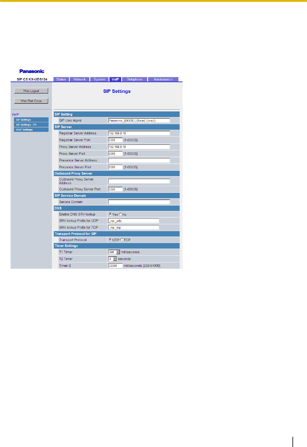
Specifying the SIP Server’s Information
Follow the procedure below to specify the IP address and port number of the SIP server to which the Super
Master CS is connected.
1. In the VoIP tab, select SIP Settings.
2. In Phone Number, enter the phone number of the SIP account.
3. In Regist Server Address, enter IP address of the SIP Registrar server.
4. In Regist Server Port, enter the port number of the SIP Registrar server that is set to communicate with
the SIP-CS.
5. In Proxy Server Address, enter the IP address of the SIP Proxy server.
6. In Proxy Server Port, enter the port number of the SIP Proxy server that is set to communicate with the
SIP-CS.
7. In Authentication ID, enter the Authentication ID of the SIP account.
8. In Authentication Password, enter the Authentication password of the SIP account.
9. Click All Save.
Installation Guide 45
4 Deployment Procedure

Specifying the Preferred Codec
Follow the procedure below to specify the codecs you want to use and their usage priorities.
1. In the VoIP tab, select VoIP Settings.
2. In CODEC Preferences, select a codec to use and specify its priority.
3. Click All Save.
46 Installation Guide
4 Deployment Procedure
4.7 PS Registration
This section shows how to register S-PS by using Web user interface.
Log in to the Web User Interface of the Super Master CS
Please refer to "Logging in to the Web User Interface" in "3.4 Basic Network Configuration" for entering Web
user interface.
Registering Extension Numbers and Extension Names for S-PSs
Follow the procedure below to assign extension numbers and extension names to the S-PSs.
1. In the System tab, select PS Registration.
2. Enter an extension name in PS Name.
3. Seledt Line1 SIP Setting or Line2 SIP Setting.
Note
Some SIP servers allow only 1 extension number per telephone. For details, refer your SIP server’s
documentation.
4. Enter the Phone Number, and enter Authentication ID and Authentication Password if necessary.
5. Click All Save.
6. Repeat steps 2 to 5 for each S-PS.
Note
If the S-PS name is too long to display, the end of the name may not be displayed on the PS’s standby
screen.
Starting Registration Mode
After you have configured the S-PS name and SIP settings, follow the procedure below to register S-PSs.
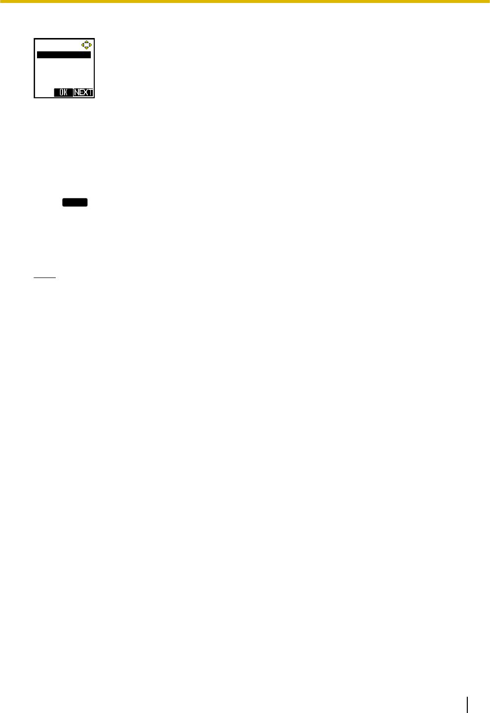
1. In the System tab, select PS Registration ® Start PS Registration.
2. Select the S-PSs to be registered in Available PS, and then click .To select all available S-PSs, click
.
To deselect S-PS(s), click or .
3. Click Next.
4. Click OK to confirm registration.
Registering S-PSs
After entering PS Registration mode, follow the procedure below to register each S-PS.
1. Turn on the S-PS.
2. Select System Option.
Tone Option
System Option
Other Option
Installation Guide 47
4 Deployment Procedure
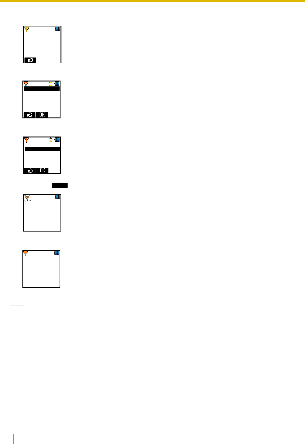
3. Enter the password.
Enter Password
_ _ _ _
4. Select Register H/S.
Register H/S
Cancel Base
Select Base
System Lock
Change PIN
5. Select a base number. You can register four separate bases on your S-PS.
Register H/S
Base 1
Base 2
Base 3
Base 4
6. Hold down
OK
until "Please wait…" is displayed.
Please Wait...
7. When registration has completed, "Registered" will be displayed.
Registered
Note
You can register multiple S-PSs continuously and simultaneously. However, PS Registration mode will
terminate if no registrations are detected within 2 minutes. All SIP-CSs controlled by the Super Master CS
will enter PS Registration mode at the same time as the Super Master CS. You can register a S-PS to any
of the SIP-CSs.
Checking Progress
You can check registration progress on the PS Registration screen.
If Registering is displayed on the left of the screen, you can check the registration status of each S-PS in the
Wireless Status field.
If Complete is displayed on the left of the screen, all S-PSs that selected for registration were registered
successfully.
48 Installation Guide
4 Deployment Procedure
Finishing Registration from S-PSs
After you have registered the S-PSs to the Air Sync Master CS, you must complete registration from each
S-PS individually.
1. Make sure that the S-PS is not registered.
Note
For details, refer to the documentation for the S-PS.
2. Press
OK
.
"HOLD DOWN OK TO REGISTER" is displayed.
3. Hold down
OK
until "Please wait…" is displayed.
4. When registration has completed, you will hear a confirmation tone and "Registered" will be displayed.
Unregistering S-PSs
If you want to unregister a specified PS, follow the procedure below.
1. Click the System tab, click PS Registration – Delete PS Registration.
2. Select the S-PSs to be unregistered in Available PS, and then click .
To select all available S-PSs, click . To deselect S-PS(s), click or .
3. Click Next.
4. Click OK to confirm unregistration.
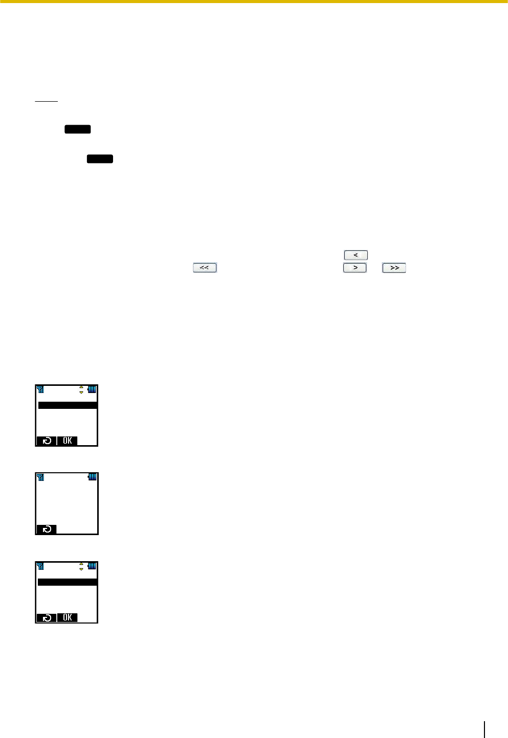
Unregistering a Base System from the S-PS
If the S-PS was outside the coverage area or was turned off when the above-mentioned unregistration
procedure was performed, you must unregister the base system manually.
1. Select "System Option".
Tone Option
System Option
Other Option
2. Enter the password.
Enter Password
_ _ _ _
3. Select "Cancel Base".
Register H/S
Cancel Base
Select Base
System Lock
Change PIN
Installation Guide 49
4 Deployment Procedure
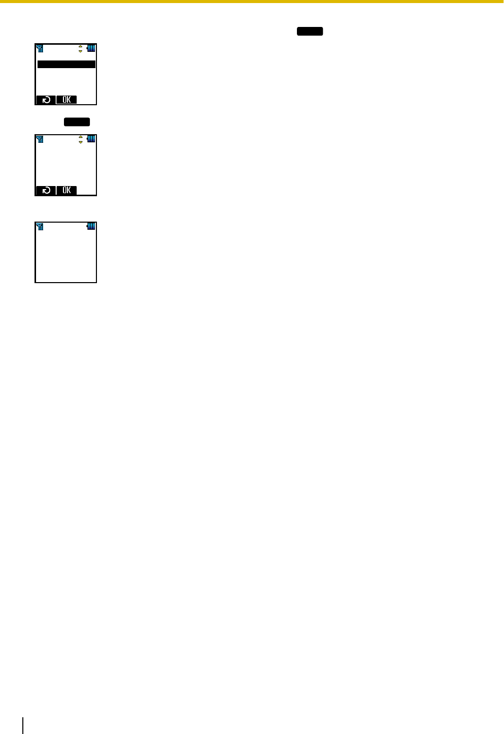
4. Select the base number for unregistration, and then press
OK
.
Cancel Base
Base 1
Base 2
Base 3
Base 4
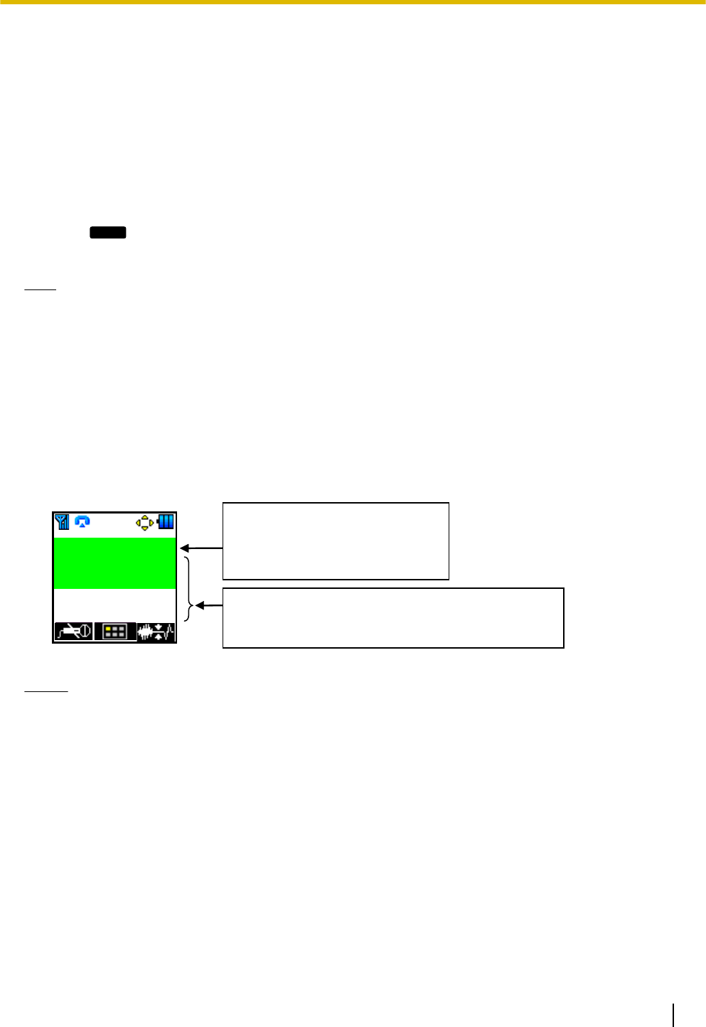
5. Press
OK
.
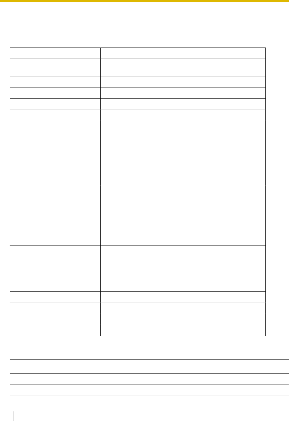
Delete?
Yes
When Unregistration has completed, "Deleted" will be displayed.
Deleted
50 Installation Guide
4 Deployment Procedure
4.8 PS Area Check
In this section, you can check the service area, handover and voice quality using 2 registered S-PSs under
actual conditions.
Entering S-PS Area Check mode
1. Start the S-PS in Maintenance mode.
For details, see "Starting the S-PS in Maintenance Mode" in "4.3 Site Survey".
2. Select "PS area check".
3. Press
OK
.
4. Repeat the procedure from 1 to 3 for another S-PS.
Note
Both S-PSs must be in PS Area check mode.
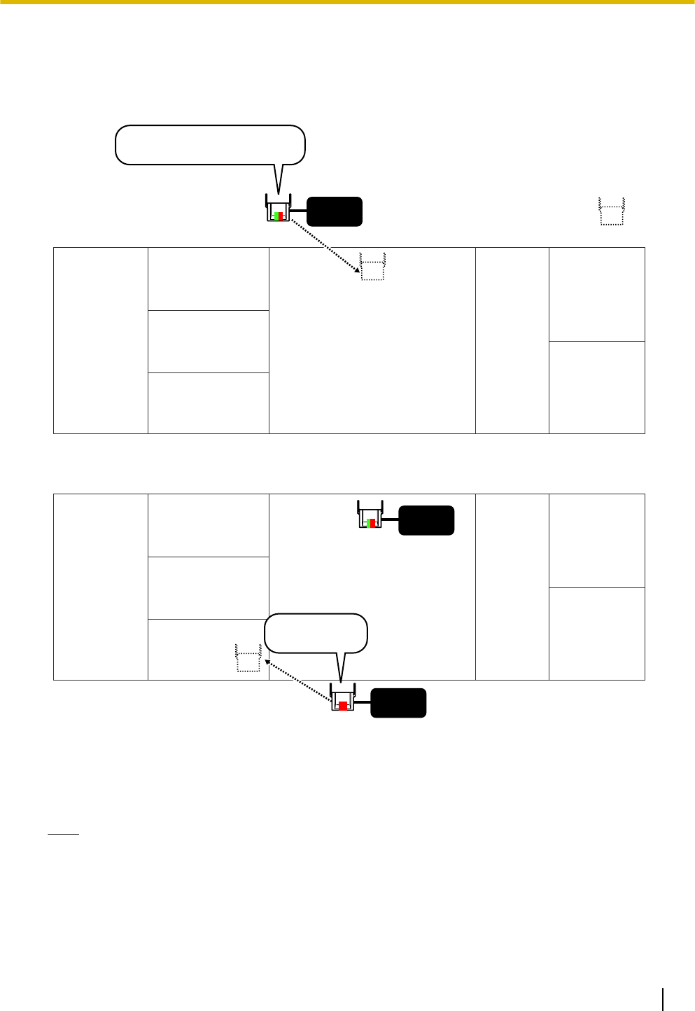
Conducting S-PS Area Check
1. Call S-PS(2) from S-PS(1).
S-PS(1) sends a tone signal to S-PS(2), and S-PS(2) returns the signal back to S-PS(1).
You can hear a tone when this signal is received.
2. Set S-PS(2) close to the SIP-CS and move around the service area listening to the tone from S-PS(1)’s
receiver to confirm voice quality and handover operation.
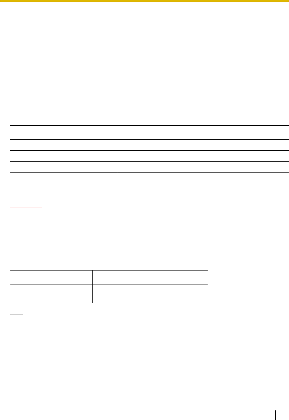
The CS-ID and signal strength of the SIP-CS you are connected to and the target SIP-CS for Handover is
displayed on the S-PS. When the signal strength is sufficiently strong, the CS-ID is displayed in green.
CS001-10 02%
012 -09 009 -08
006 -68
017 -06 008 -05
014 -05 004 -04
CSnnn-xx yy%
nnn : Current sync CS ID
xx : RSSI level
yy : Error rate
Detected CS IDs and RSSI level are displayed.
If the RSSI level exceeds the threshold,
it is displayed with green shading.
Notice
When checking the PS area, ensure that at least one SIP-CS is displayed in green on the LCD of the
handset within the service area.
Installation Guide 51
4 Deployment Procedure

5 Troubleshooting
Tree Survey Error Messages and Notices
When an error occurs during or after the Tree Survey, an error message or notice is displayed.
Messages displayed during the Tree Survey
Message Probable Cause Solution
The Tree Survey can not
be executed because
software shown below
does not support the Tree
Survey.
The selected SIP-CS uses an older
software version not supported by the
Tree Survey feature.
Please update the software to version
7.100 or later.
SIP-CS(s) will not function
correctly because air
synchronisation has not
been established.
Location of the SIP-CS is not good. Please move the SIP-CS(s) closer to
the adjacent SIP-CS according to site
planning.
If you still have trouble, there may be
interference from external wireless
equipment. Please locate the source
and eliminate it.
Connection error. IP network environment and settings
are incorrect.
Please check the network connection
of the SIP-CS(s) and PC.
SIP-CS(s) will not function
correctly because there is
interference from external
wireless equipment.
There may be interference with
DECT radio waves.
Please locate the source of
interference and eliminate it.
Messages displayed when the Tree Survey is complete
Message Probable Cause Solution
Notice Sync Slave CS does
not have Secondary-CS.
One or more SIP-CSs could not have
a Slave CS assigned for reasons
such as avoiding the creation of a
loop. However, this is not a problem.
Please move the SIP-CS(s) closer to
the adjacent SIP-CS according to site
planning.
Loops may occur when SIP-CSs are
assigned a Slave CS. In this case,
please reconduct site planning.
ERROR!!! Parameter
Error.
Monitoring of SIP-CSs failed. Conduct the Tree Survey again.
ERROR!!! CS does not
have Primary CS.
A SIP-CS is located far from the
adjacent SIP-CS.
Please move the SIP-CS(s) closer to
the adjacent SIP-CS according to site
planning.
ERROR!!! Survey result
contains more than 4
levels.
Air synchronisation hierarchy
contains more than 4 levels.
Please recheck the design of your
Tree Structure and relocate
SIP-CS(s) to remove the
unsupported level(s).
52 Installation Guide
5 Troubleshooting

Message Probable Cause Solution
ERROR!!! IP-CS is too
close.
SIP-CSs are located too close
together.
As a guideline, the maximum number
of SIP-CSs in an area with a radio
signal strength of "11" is 2.
Please relocate the SIP-CS(s). Refer
to the guidelines for distance
between SIP-CS(s) in "Required
Distances between Equipment".
Installation Guide 53
5 Troubleshooting
6 Appendix
SIP-CS Specification
Type 4 channel CS with wideband audio
Supported Audio Wideband
Narrowband
Radio Method DECT
VoIP Signalling Protocol SIP
IP Port Number Flexible Setting Yes
Local Setting Yes (through Web application)
Site Survey Mode Yes (through Web application)
Initialisation Yes (through Web application)
Maximum Simultaneous Calls 4
Power Supply PoE
(IEEE 802.3af)
Optional AC adaptor
(KX-A239 [PQLV206YB]/KX-A239X [PQLV206YB])
Codec G.722 for Wideband
(Used for LAN and broadband remote IP network)
G.711 for Narrowband
(Used for LAN and broadband remote IP network)
G.729a for Narrowband
(Used for narrowband remote IP network)
LAN Port 10 BASE-T
100 BASE-TX
VLAN Yes (802.1Q)
IP Addressing DHCP
Static IP Address Setting
Software Upgrade Yes
Built-in VPN No
Weight 290 g
Size (W) 190 mm ´ (H) 133.9 mm ´ (D) 39.3 mm
PS Specification
Items KX-UDT111 KX-UDT121
Type Standard Slim & Light
Radio Technology
54 Installation Guide
6 Appendix
Items KX-UDT111 KX-UDT121
LCD 1.8 inch colour 1.8 inch colour
Bluetooth No Yes
Vibration Yes Yes
Battery Ni-MH Li-Ion
Number of Simultaneous Registered
Systems
4
Software Upgrade Yes (Wireless Download)
RF Specification
Item Description
Radio Access Method MultiCarrier TDMA-TDD
Frequency Band 1920 MHz to 1930 MHz
Number of Carriers 10
Carrier Spacing 1728 kHz
Transmission Output Peak 250 mW
CAUTION
•The SIP-CS should be kept free of dust, moisture, high temperature (more than 40 °C), low temperature
(less than 0 °C), and vibration, and should not be exposed to direct sunlight.
•The SIP-CS should not be placed outdoors (use indoors).
•The SIP-CS should not be placed near high-voltage equipment.
•The SIP-CS should not be placed on a metal object.
Compatible S-PSs
Item Model No.
S-PS •KX-UDT111
•KX-UDT121
Note
•For more details about S-PSs, refer to the documentation for your S-PS.
Required Distances between Equipment
CAUTION
Maintain the distances listed below between equipment in order to prevent noise, interference or the
disconnection of a conversation. (The distance may vary depending on the environment.)
Installation Guide 55
6 Appendix

Equipment Distance
CS and office equipment such as a computer, telex, fax
machine, etc.
More than 2 m (6 ft 7 in)
CS and PS More than 1 m (3 ft 3 in)
Each CS More than 3 m (10 ft)
Each PS More than 0.5 m (1 ft 8 in)
SIP server and CS More than 2 m (6 ft 7 in)
Notice
If multiple SIP-CSs provide service in the same area, the phone connection may become noisy or the
number of possible simultaneous calls with S-PSs may decrease due to interference between the SIP-CSs.
The required distance between SIP-CSs may vary depending on the environment of the installation site
and conditions in which the wireless system is used. Conduct a site survey to determine the appropriate
distance.
56 Installation Guide
6 Appendix

Installation Guide 57
Notes

Copyright:
Panasonic System Networks Co., Ltd. 2012
DD0412US0 (v01.000)
PNQX3730ZA
This material is copyrighted by Panasonic System Networks Co., Ltd., and may be reproduced for internal
use only. All other reproduction, in whole or in part, is prohibited without the written consent of Panasonic
System Networks Co., Ltd.
One Panasonic Way, Secaucus, New Jersey 07094
http://www.panasonic.com/bts
5770 Ambler Drive, Mississauga, Ontario, L4W 2T3
http://www.panasonic.ca