Panasonic of North America 9TAWV-TW37003 Common Trigger Box User Manual Installation manual
Panasonic Corporation of North America Common Trigger Box Installation manual
Contents
- 1. Installation manual
- 2. Users manual
- 3. 05 Short-Term Confidential_User Manual
Installation manual

16
Install the Common Trigger Box (option: WV-TW37003)
Preface
• If a Common Trigger Box installed in the trunk, for example, and a BWC are connected via
Bluetooth communication, it is possible to activate the BWC controlling from the external
devices or transfer BWC's operating information to the external devices.
• By connecting the Common Trigger Box and Pairing Dock (option: WV-TW37004) using an
Ethernet cable, Bluetooth peer-to-peer wireless communication can be performed.
• If the Common Trigger Box is connected with SA366 (existing model BWC) equipped with
wireless function, it is possible to activate the SA366 automatically controlling from the external
devices or transfer SA366's operating information to the external devices.
WARNING
• To prevent fire or electric shock hazard, do not expose this apparatus to rain or moisture.
Standard accessories
Operating instructions ..............................1 pc.
Warranty card ...........................................1 pc.
Common Trigger Box fixing screws ......... 5 pcs.
(of them, 1 for spare)
Fixing plate ...............................................1 pc.
17
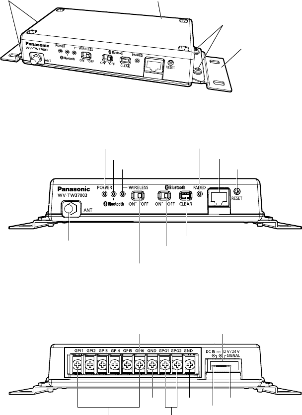
Part names
Common Trigger Box
(option: WV-TW37003)
Common Trigger Box fixing screws (2 pcs.)
(accessory: WV-TW37003)
Common Trigger Box fixing screws (2 pcs.)
(accessory: WV-TW37003)
Fixing plate
(accessory: WV-TW37003)
<Front View>
POWER indicator
ANT terminal
WIRELESS
ON/OFF SW
Bluetooth
ON/OFF SW
Bluetooth CLEAR SW
Bluetooth indicator
WIRELESS indicator
PAIRED inducator
RESET SW
RJ45 terminal
<Rear View>
GP IN 1 - 6
GP I/O terminal DC IN terminal
GP OUT 1 - 2
GND GND
PIN q
PIN r
18
■ Indicator
POWER indicator Lights up in green when power is supplied to the Common Trigger
Box.
Bluetooth indicator Lights up in green when Bluetooth ON/OFF SW sets to ON.
Blinking in green(0.5 sec./0.5 sec.) when pairing between the Com-
mon Trigger Box and BWC (at least 1 unit) is complete. Up to 10
BWCs can be connected.
WIRELESS indicator Lights up in green when WIRELESS ON/OFF SW sets to ON.
Blinking in green(0.5 sec./0.5 sec.) when linking between the Com-
mon Trigger Box and SA366 (at least 1 unit) is complete. For SA366
(existing model), up to two units can be linked.
Fast blinking in green (0.25 sec./0.25 sec.) when authentication error
is occurred.
PAIRED indicator Lights up in green when connecting between Common Trigger Box
and BWC through the ethernet cable.
■ SW
WIRELESS ON/OFF SW Determines whether to operate the Common Trigger Box via wireless
LAN mode.
Bluetooth ON/OFF SW Determines whether to operate the Common Trigger Box via Blue-
tooth mode.
Bluetooth CLEAR SW Clear the pairing information between the Common Trigger Box and
the BWC.
RESET SW Restart the Common Trigger Box.
■ Front Terminal
RJ45 terminal Connects with the Pairing Dock using an Ethernet cable, and
enables pairing operation.
RJ45 terminal is a dedicated connecting terminal for a Pairing Dock.
It cannot be used for connecting a regular LAN cable.
ANT terminal Connects an external antenna.
■ Rear Terminal
GP I/O terminal Connects signal lines from the external devices.
Input: 6 lines, Output: 2 lines
Input specification: No-voltage make contact input
(4 V - 5 V DC, internally pulled up)
OFF: Open or 4 V - 5 V DC
ON: Make contact with GND (required drive current: 1 mA or more)
Output specification: Open collector output
(maximum applied voltage: 20 V DC)
ON: 4 V - 5 V DC by internal pull-up
OFF: Output voltage 1 V DC or less
(maximum drive current: 50 mA)
DC IN terminal Pin q GND (Black)
Pin w DC IN (Red: Supplies power from the power source of 12 V
DC/24 V DC)
Pin e ACC (White: Detects ACC signal on by car key operation.)
Pin r NC
19
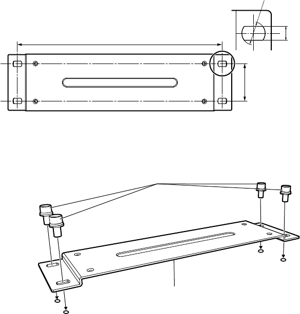
How to install
q Referring to the illustration below, drill the fixing holes on the flat mounting surface.
(For the hole diameter and depth of the screws (locally procured), refer to the specification of
each screw to be used.)
4-ø10 mm
{13/32 inches}
40 mm {1-9/16 inches}
220 mm {8-21/32 inches}
6 mm
{1/4 inches}
w Fix the fixing plate (accessory: WV-TW37003) on the installation surface using fixing screws
(locally procured).
The minimum required pull-out capacity of a single screw is 196 N {44 lbf} or more.
Fixing plate (accessory: WV-TW37003)
Screws (M5, 4 pcs.: locally procured)
Fixing plate TOP view
20
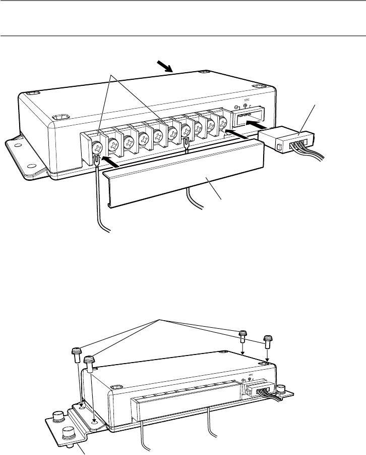
e Connect a 4P power cable to the back of the Common Trigger Box. Also after removing the
protective cover, connect signal lines for external devices, GND line to the GP I/O terminal, and
external antenna to the ANT terminal.
Note:
• Attach the protective cover to the GP I/O terminal after fixing the connectors to the terminal
with screws.
GPI1 GPI2 GPI4
GPI3 GPI5 GPI6 GND
GND DC IN 12V/24V
GPO1 GPO2
SIGNAL
Connector from the external device
From Panasonic MK 3 Lind
Distribution Box
External antenna (locally procured)
Protective cover for GP I/O terminal
r Fix the Common Trigger Box to the fixing plate using Common Trigger Box fixing screws
(accessory: WV-TW37003).
(Recommended tightening torque: 0.78 N·m {0.58 lbf·ft})
GPI1 GPI2 GPI4
GPI3 GPI5 GPI6 GND
GND DC IN 12V/24V
GPO1 GPO2
SIGNAL
Fixing plate (accessory: WV-TW37003)
Common Trigger Box fixing screws
(accessory: WV-TW37003)
21
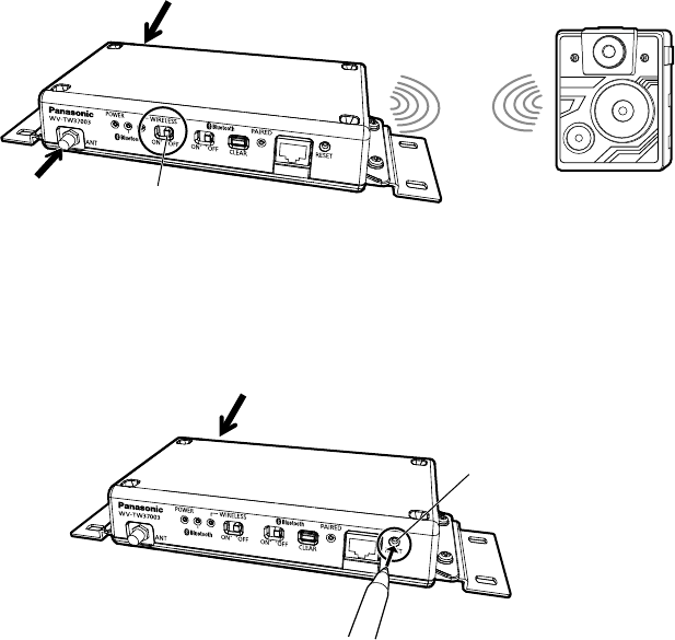
How to use
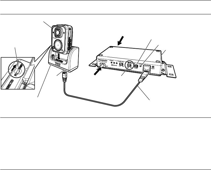
<Using with Pairing Dock (option: WV-TW37004)>
1. After setting the BWC to the Pairing Dock, connect the Pairing Dock with the Common Trigger
Box using an Ethernet cable.
2. Select PAIRED for the PAIRED SW of the Pairing Dock, and select ON for Bluetooth ON/OFF
SW of the Common Trigger Box. (☞ Page 28)
3. When power is supplied to the Common Trigger Box, pairing will be started automatically and
Bluetooth connection between the BWC and Common Trigger Box are enabled. (The PAIRED
indicator will be lit in green.)
4. Press Bluetooth CLEAR SW to cancel the Bluetooth connection with the BWC.
Note:
• The BWC can be charged from the Common Trigger Box as it is set on the Pairing Dock.
Bluetooth CLEAR SW
PAIRED inducator
RJ45 terminal
Connect to the
power source.
Common Trigger Box
(option: WV-TW37003)
Bluetooth
ON/OFF SW
(Set to ON)
RJ45
terminal
Ethernet cable
(locally procured)
BWC
Connect to the
external ANT
(locally procured).
PAIRED SW (PC⇔PAIRED)
(Set to PAIRED)
Pairing Dock
(option: WV-TW37004)
Note:
• Once pairing is activated, the PAIRED information will be recorded to the BWC for 12 hours.
After 12 hours, recorded information will be deleted.
(This function is disable as default, you need to configure the BWC to delete after 12 hours.
and the duration (12 hours) can be configurable.)
• If pairing with a different Common Trigger Box is activated within 12 hours, the old data will be
overwritten with the new PAIRED information.
• Approximately 10 seconds is required for pairing.
22
<Using Common Trigger Box with the existing model SA366>
Set the WIRELESS SW of the Common Trigger Box to ON, and supply power to the Common Trig-
ger Box.
Set "ST1" for the Wireless LAN SW of SA366.
The Common Trigger Box and SA366 will be automatically connected via Wireless LAN.
SA336 (existing model)
Wireless LAN
WIRELESS SW
(Set to ON)
Connect to the power source.
Connect to the
external ANT
(locally procured).
<Initializing the Common Trigger Box>
To restart the Common Trigger Box, press the RESET SW using a nib of a pen or the like with the
power on condition for more than 10 seconds.
Connect to the power source.
RESET SW