Panasonic of North America 9TAWX-CT2020 Order Taker for Wireless Communication System User Manual 3TR001747AAA SAMPLE
Panasonic Corporation of North America Order Taker for Wireless Communication System 3TR001747AAA SAMPLE
User Manual
Before attempting to connect or operate this product,
please read these instructions carefully and save this manual for future use.
Order Taker Unit
Operating Instructions
Model No. WX-CT2020
A
B
WX-CT2020
SAMPLE

2
The serial number of this product may be found in the bat-
tery compartment of the unit.
You should note the serial number of this unit in the space
provided and retain this book as a permanent record of your
purchase to aid identification in the event of theft.
Model No. WX-CT2020
Serial No.
CAUTION
It is a violation of Federal Law to begin operating this sys-
tem prior to obtaining an FCC Radio License. The FCC ID
number for this radio equipment is listed below.
FCC ID: ACJ9TAWX-CT2020
Danger of explosion if battery is incorrectly replaced.
Replace only with the same or equivalent type.
ATTENTION:
A battery that is recyclable powers the product
you have purchased. Please call 1-800-8-BAT-
TERY for information on how to recycle this bat-
tery.
Ni-MH
FEDERAL COMMUNICATIONS COMMISSION INTERFERENCE STATEMENT
This equipment has been tested and found to comply with the limits for a Class A digital device, pursuant to part 15 of the
FCC Rules. These limits are designed to provide reasonable protection against harmful interference when the equipment is
operated in a commercial environment. This equipment generates, uses, and can radiate radio frequency energy and, if
not installed and used in accordance with the instruction manual, may cause harmful interference to radio communications.
Operation of this equipment in a residential area is likely to cause harmful interference in which case the user will be
required to correct the interference at his own expense.
FCC Warning: To assure continued FCC emission limit compliance, use only the provided power supply cord and shielded
interface cable when connecting this device to the computer. Also, any unauthorized changes or modifications to this
equipment would void the user's authority to operate this device.
This device complies with Part 15 of the FCC Rules. Operation is subject to the following two conditions: (1) This device
may not cause harmful interference, and (2) this device must accept any interference received, including interference that
may cause undesired operation.
Responsible Party: Matsushita Electric Corporation of America
1707 N. Randall Rd., Elgin IL. 60123
Contact Source: Panasonic Digital Communications & Security Company
866-472-6767

3
INTRODUCTION
Panasonic WX-CT2020 Order Taker Unit is designed for the use in Panasonic Wireless Communication System. Using with
WX-C1027A Headset (option), you can communicate by voice with other store personnel and the customer.
FEATURES
• Compatible center modules: WX-C1010, WX-C1011, and WX-CC2010 (Refer to "SW#8" on p. 7 "DIP Switch Setup".)
• Noise and interference reduction by use of UHF band
• Facilitated frequency setting by use of phase lock loop (PLL)
• A/B channel selection available for double drive-through (DDT) (Refer to "SW#2" on p. 7 "DIP Switch Setup".)
• Talk mode selectable between Talk Lock and Talk PTT (Refer to p. 9 "Optional Mode Setup".)
• Page mode selectable between Page Lock and Page PTT (Refer to p. 9 "Optional Mode Setup".)
PRECAUTIONS
•All setup procedures of this product should be performed by qualified service personnel or system installers.
•Use only Panasonic authorized batteries like the rechargeable Ni-MH 3.6 V.
•Follow the battery care and handling instructions.
•Read the instructions included with the battery charger.
•Charge the battery when the power indicator lights up in red and a beep is heard in the headset. Fully charge the battery.
Failure to do so may shorten the operating time.
CONTENTS
CONTENTS ............................................................................................................................................... 3
INTRODUCTION ....................................................................................................................................... 3
FEATURES ................................................................................................................................................ 3
PRECAUTIONS ......................................................................................................................................... 3
NAMES & FUNCTIONS .............................................................................................................................. 4
BATTERY LOADING & REPLACEMENT ................................................................................................... 6
●Loading .............................................................................................................................................. 6
●Replacement ...................................................................................................................................... 6
SETUP PROCEDURES .............................................................................................................................. 6
●Opening the Switch Pocket ................................................................................................................ 6
●Channel Group Selection ................................................................................................................... 7
●DIP Switch Setup ................................................................................................................................ 7
●Channel Interference Check .............................................................................................................. 7
●Operation Mode Setup ....................................................................................................................... 9
OPERATING PROCEDURES ..................................................................................................................... 11
●Turning the Power On/Off ................................................................................................................... 11
●Communications with Customers (TALK) ...........................................................................................11
●Communications with Other Store Personnel (PAGE) ........................................................................ 12
WHEN DISCONNECTING THE HEADSET PLUG ...................................................................................... 12
TROUBLESHOOTING ................................................................................................................................ 13
SPECIFICATIONS ...................................................................................................................................... 14
STANDARD ACCESSORIES ..................................................................................................................... 14
OPTIONAL ACCESSORIES ....................................................................................................................... 14
4
EJECT
WX-CT2020
AB
PWRVOL
ui
!2
o !0
!1 q
y
q w e r t
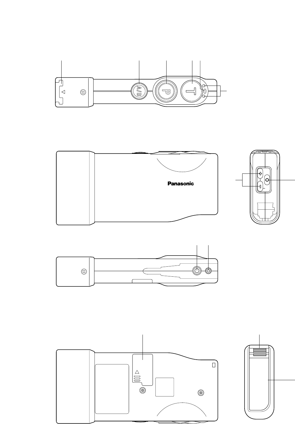
NAMES & FUNCTIONS

5
qBattery Lock [EJECT]
When removing the battery, slide out the lock.
When loading a new battery, insert the battery until the
lock clicks.
wA/B Channel Selection Button [A/B]
This button switches frequencies from Channel A to B
and vice versa. The channel indicator y displays the
selected channel in red (A) or green (B).
ePage Button [P]
This button controls communications with store person-
nel.
While the button is held down in the Page PTT mode,
you can speak to store personnel. When the button is
pressed in the Page Lock mode, you can speak to the
store personnel until you press a button a second time.
When the button is released, you can hear the commu-
nication among store personnel.
rTalk Button [T]
This button controls communications with the customer.
While the button is held down in the Talk PTT mode, you
can speak to the customer who is at the menu board.
When the button is pressed in the Talk Lock mode, you
can speak to the customer until you press the button a
second time.
When the button is released, you can hear the cus-
tomer.
tPower Indicator
The indicator shows the status as follows.
Green ON: Power is supplied, and the unit is oper-
ating.
Red ON: The battery requires recharging.
Red Blink: The channel selector (refer to p. 7) is set
to a wrong position.
yChannel Indicator
While lighting in red or green, this indicator shows
which channel is in operation.
Red lighting: Channel A is selected.
Green lighting: Channel B is selected.
Red blinking: Channel A is being selected, and either
the Talk or Page mode is activated.
Green blinking: Channel B is being selected, and
either the Talk or Page mode is activated.
uVolume Control Buttons [VOL ▲▼]
Pressing the respective buttons will increase or
decrease the sound level.
iPower Button
Pressing this button for one second will turn the order
taker unit on or off.
oEarphone Input Jack
This jack is used for connection with WX-C1027A
Headset.
!0 Microphone Input Jack
This jack is used for connection with WX-C1027A
Headset.
!1 Switch Pocket
Do not open the lid of this pocket. Should be opened
only by qualified service personnel or system installers.
!2 Battery (Optional accessory)
Refer to p. 3 PRECAUTIONS.
6
SETUP PROCEDURES
Caution: Setup of this product should only be performed
by qualified service personnel or system installers.
●Opening the Switch Pocket
1. Press the power button to turn off the order taker unit.
2. Open the switch pocket by moving the lid.
3. Set the channel selector and DIP switches. (Refer to
p. 7 "Channel Group Selection, "DIP Switch Setup", and
"Channel Interference Check".
4. After finishing the setup, close the switch pocket by
moving the lid.
5. Turn on the order taker unit.
Notes: Be sure to turn off the order taker unit in Step 1.
Otherwise, the channel group (refer to p. 7 "Channel
Group Selection") will not be activated until you turn off
and on the power again.
●Turning the Power On/Off
1. Press the power button to turn on the order taker unit.
2. After using the order taker unit, press the power button
again to turn off the unit.
q
w
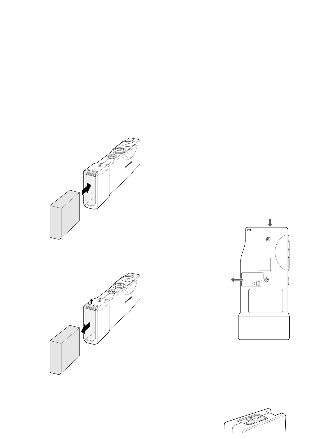
BATTERY LOADING &
REPLACEMENT
Notes:
•Refer to the operating instructions included with the
battery and battery charger.
•Prepare a fully charged battery.
•Battery replacement is recommended when the power
indicator lights up in red and a constant beep is heard
in the headset.
●Loading
Insert the battery as shown in the figure.
Note: Be sure to insert it until the lock clicks.
EJECT
WX-CT2020
●Replacement
1. Slide the battery lock to the upside.
2. Remove the battery.
EJECT
WX-CT2020
q
w
PWR
VOL
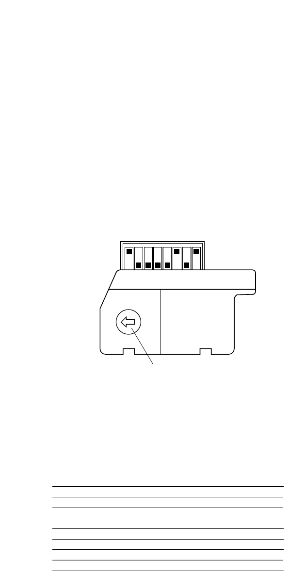
●Channel Group Selection
You can select a channel group by setting the channel
selector, which is the rotary switch inside the switch pocket.
1. Press the power button to turn off the order taker unit.
2. Set the switch to the channel group.
Available Channel Group: 1 - 8
Notes:
•When a switch position other than 1 through 8 is select-
ed, the power indicator will blink in red.
•Be sure to turn off the order taker unit in Step 1.
Otherwise, the channel group will not be activated until
you turn off and on the power again.
●DIP Switch Setup
An eight-bit DIP switch is provided for system setups. The
initial settings are marked with an asterisk *.
1. Press the power button to turn off the order taker unit.
2. Set the switches as follows.
SW#1: For selection of a radio frequency suitable for
the location
ON: Applies the US frequency to the headset.
OFF: Applies the Canadian frequency.
7
1
2
3
4
56
7
8
G
1 2 3 4 5 6 7 8
Channel selector
1
SW#
2
3
4
5
6
7
8
Location
Function
DDT/SDT
Manager Mode
Role Assignment
Area Expansion
Tone Squelch
Talk Lock Resumption
Compatibility
USA*
ON
Double Drive Thru
ON
Manager
Expand
ON*
ON
WX-C1010/WX-C1011
Canada
OFF
Single Drive Thru*
OFF(Normal)*
Assistant*
Normal*
OFF
OFF*
WX-CC2010*
SW#2: Refer to the Operating Instructions included with
the WX-CC2010.
SW#3: Refer to WX-CC2010 Operating Instructions.
SW#4: Refer to WX-CC2010 Operating Instructions.
SW#5: Refer to WX-CC2010 Operating Instructions.
SW#6: Enables or disables the tone squelch function.
ON: Outputs audio after detecting the tone squelch.
OFF: Outputs audio disregarding the tone squelch.
Note: Normally, set SW#6 to ON. Pay attention to a
high level noise that may be output when set to
OFF.
SW#7: While talking with a customer in the Talk Lock
mode, you may need to contact store personnel in
the Page PTT or Page Lock mode, which interrupts
the Talk Lock mode. This switch specifies the status
of the interrupted Talk Lock mode after ending the
Page PTT or Page Lock mode.
ON: Resumes the Talk Lock mode.
OFF: Releases the Talk Lock mode.
SW#8: Specifies the system compatibility.
ON: Is compatible with the center modules WX-
C1010 and WX-C1011.
OFF: Refer to WX-CC2010 Operating Instructions.
Notes:
•Be sure to turn off the order taker unit in Step 1.
Otherwise, the channel group (refer to "Channel
Group Selection") will not be activated until you turn
off and on the power again.
•SW#6 and SW#8 are used for channel interference
check while turn on the headset.
●Channel Interference Check
SW#6 and SW#8 have the specific function of checking
whether or not there is radio wave interference in the select-
ed channel group.
1. Press the power button to turn off the order taker unit.
<When WX-C1010 or WX-C1011 is used for the cen-
ter module>
2. Set the switches as follows, and turn on the headset.
A noise will be heard in the headset.
SW#6: OFF
SW#8: ON

8
3. Listen to the sound while repeatedly pressing the [A/B]
button.
Only random noise will be heard if there is no interfer-
ence. The presence of any sound other than noise indi-
cates that there is interference.
<When WX-CC2010 is used for the center module>
2. Set the switches as follows, and turn on the headset.
A noise will be heard in the headset.
SW#6: OFF
SW#8: OFF
3. Listen to the sound.
(Refer to the operating instructions of the center mod-
ule.)
4. Reselect the channel groups if there is any interference.
Note: Be sure to turn off the order taker unit in Step 1.
Otherwise, the channel group (refer to p. 7 "Channel
Group Selection") will not be activated until you turn
off and on the power again.
9
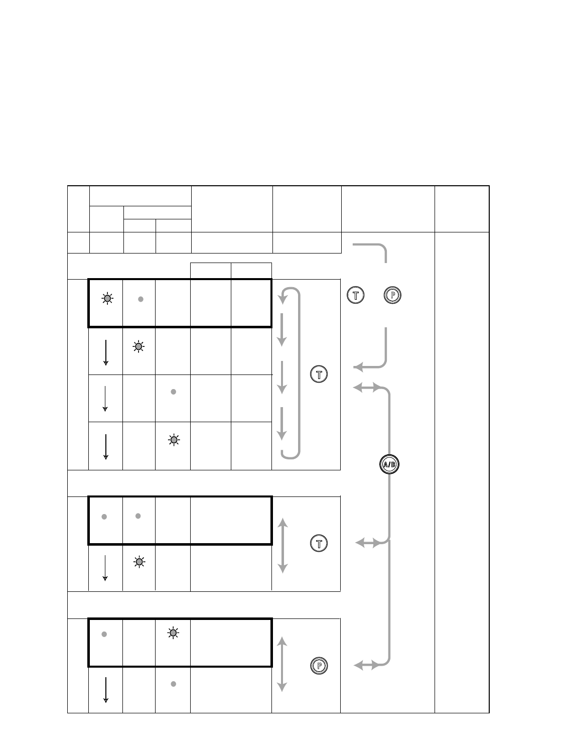
● Operation Mode Setup
Three operation modes can be set up to adapt the order taker unit to your requirements. (Refer to the diagram for details.)
• Default channel and A/B Button Enable/Disable setup
• Talk lock/ Talk PTT
• Page lock/Page PTT
Note: The next page describes how to set up the order taker unit.
Indicator
Selected Mode Selection Transition Exit
Off
Power A/B channel
Red Green
Default Channel Setup
Selected
Channel A/B Button
A
B
Enable
Disable
Talk Setup
Talk Lock
Talk PTT
Page Setup
Page PTT
Page Lock
• PTT means "press to talk."
• The default settings are enclosed in bold lines on the table.
Blink On
Blink
Blink
On
On On
On
On
Blink
Blink
A
BEnable
Disable
Press
POWER .
——— —
—
—
—
—
—
—
While holding down
and buttons,
press POWER .
—
—
—
10
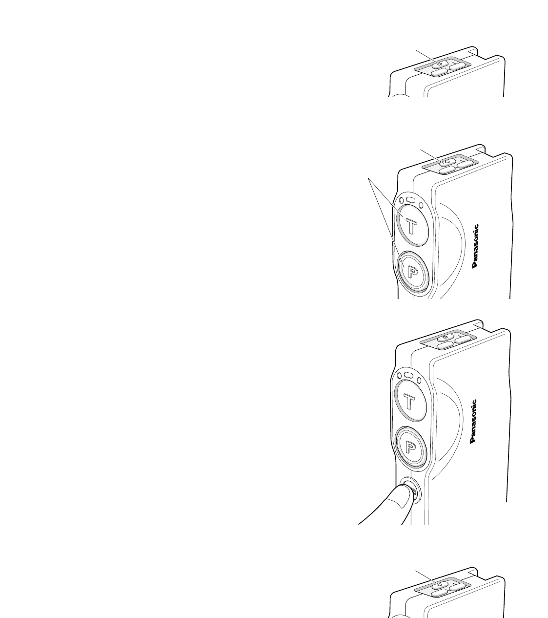
1. Press the power button to turn off the order taker unit.
2. While holding down the buttons T and P simultaneously,
press the power button to turn on the order taker unit.
The order taker unit enters the setup mode where the
indicators and buttons have different functions than in
normal operation.
3. Select a default channel setup from four options, press-
ing the button T.
4. Press the button A/B to move to the talk setup and page
setup.
5. Press the button T to select a talk mode.
6. Press the button P to select a page mode.
7. Press the button A/B to confirm that the indicators show
the three modes selected for the default channel, talk
and page.
8. Press the power button to turn off the order taker unit,
and then turn it on again. The newly selected operation
mode will be applied to the order taker unit.
WX-CT2020
A
B
PWR
VOL
Power on.
Keep holding down.
WX-CT2020
A
B
PWR
VOL
PWR
VOL
Power button
PWR
VOL
Power button
11
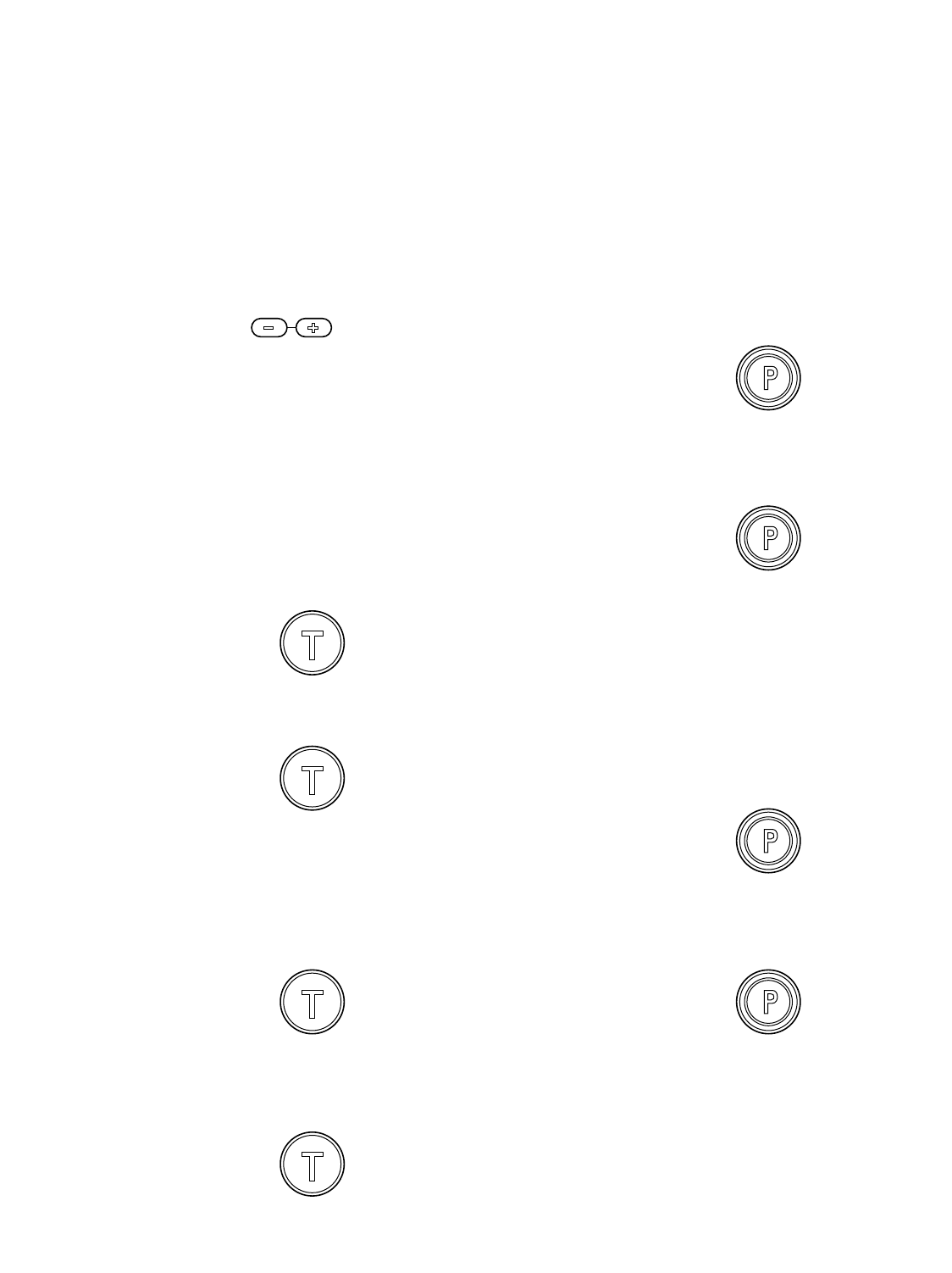
●Communications with Other Store
Personnel (PAGE)
Store personnel wearing the headset can communicate
with each other without being heard by customers.
<When the Page Lock mode is preset>
1. Press the button P and speak into the microphone at a
normal level.
A short beep repeats in the headset to notify all store
personnel that the system operates in the page mode.
2. Press the button P again to release the lock and listen
to the response from other store personnel.
<When the Page PTT mode is preset>
1. Hold down the button P and speak into the microphone
at a normal level.
A short beep repeats in the headset to notify all store
personnel that the system operates in the page mode.
2. Release the button and listen to the response from
other store personnel.
Notes:
•Transmission using the talk button T or P is allowed for
a single headset at a time. A continuous beep or dis-
torted sound will be heard in a headset when a person
wearing the headset presses the button T or P while
another person is operating.
•Maintain a distance of more than 0.3 m {1 ft.} between
the headset and the order taker, or more than 1 m {3 ft.}
between the headset and the center module.
•Prior to operating the order taker unit, confirm that the
system setup for the order taker unit, center module,
and other devices has been completed.
OPERATING PROCEDURES
●Communications with Customers
(TALK)
Any store personnel wearing the headset can communicate
bidirectionally with any customer who is at the menu board.
1. Select a proper sound level by pressing the button + or
–.
2. You will hear a tone in the headset when a vehicle
arrives at the menu board.
Note: The tone duration varies depending on the set-
tings made in the center module.
<When the Talk PTT mode is preset>
1. Hold down the button T and speak to the customer.
A short beep repeats in the headset.
2. Release the button and listen to the customer.
<When the Talk Lock mode is preset>
1. Press the button T and speak to the customer.
A short beep repeats in the headset.
2. Press the button again to release the lock and listen to
the customer.
Hold down
Release
Press
Press again
Hold down
Press
Press again
Release
12
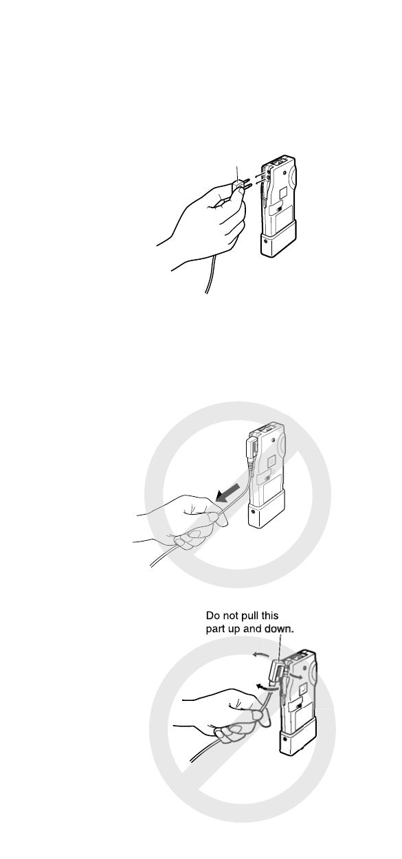
WHEN DISCONNECTING THE
HEADSET PLUG
When disconnecting the headset plug from this product,
pull the plug straight, holding the resin-molded part.
Do not hold the cable or pull the resin-molded part up and
down. That may cause trouble.
Pull the plug straight,
holding this part.
Do not hold the cable.

13
TROUBLESHOOTING
Phenomenon
The power indicator blinks in red.
The power indicator lights up in red
and a constant beep is heard in the
headphone.
Cannot turn on the order taker unit.
Cannot communicate with other
store personnel or the customer at
the menu board.
Cannot listen or talk to the
customer, while communications
with the store personnel are OK.
Cannot "page" or "talk" in certain
areas.
Possible Cause
A wrong channel is selected.
(The channel selector is set to the
wrong position. Refer to p. 7.)
The battery power is nearing its end.
The battery is exhausted.
The battery is not inserted correctly.
The center module may be turned off.
The vehicle detector may malfunction
because the detector is not plugged
into the center module, no power is
supplied, or the detecting function is
out of order.
Radio wave intensity is insufficient in
the areas.
What to do
Select any of channels 1 through 8.
If no remedy exists, consult your dealer
for repairs.
Recharge the battery.
Recharge the battery.
Position the battery properly. (Refer to p. 6.)
Turn on the power switch of the center
module. (Refer to the operating
instructions of the center module.) If no
remedy exists, consult your dealer for
repairs.
Check that the vehicle detector is
plugged in and is supplied power.
(Refer to WX-CC2010 Installation
Manual.)
If no remedy exists, consult your dealer
for repairs.
• Remove any metal obstacles blocking
radio waves, or try the following reme-
dy.
•WX-C1010/WX-C1011: Extend the
transmission antennas.
WX-CC2010: Please add WX-CT2030
Transceiver.

14
SPECIFICATIONS
Operating Frequency: UHF/FM
Type of Radio Wave: F3E
Required Power Supply: Rechargeable Ni-MH Battery, 3.6 V DC
Control Function: Power (On/Off)
Volume (Up/Down)
Talk
Page
Channel Selection (A/B)
Channel Group Selection (1-8)
DIP Switch Setup (8 bit)
Dimensions: 139 mm (W) x 63 mm (H) x 26 mm (D)
{5-1/2 in. (W) x 2-1/2 in. (H) x 1 in. (D)}
Weight (excluding battery): 110 g{0.24 lbs}
Dimensions and weighs indicated are approximate.
Specifications are subject to change without notice.
STANDARD ACCESSORIES
Miniature Screwdriver ....................................................... 1
OPTIONAL ACCESSORIES
Battery (Ni-MH 3.6 V DC, 1 100 mA/h).............................. 2020BAT
Battery Charger................................................................. 2020CH
Headset............................................................................. WX-C1027A
Ni-MH


PANASONIC CANADA INC.
5770 Ambler Drive, Mississauga,
Ontario, L4W 2T3 Canada (905)624-5010
Panasonic Digital Communications & Security Company
Unit of Matsushita Electric Corporation of America
Information Systems Group
Zone Office
1707 N.Randall Road, Elgin, IL 60123 (866) 472-6767
2003 © Matsushita Electric Industrial Co., Ltd. All rights reserved. NM0703-0 3TR001747AAA Printed in Japan