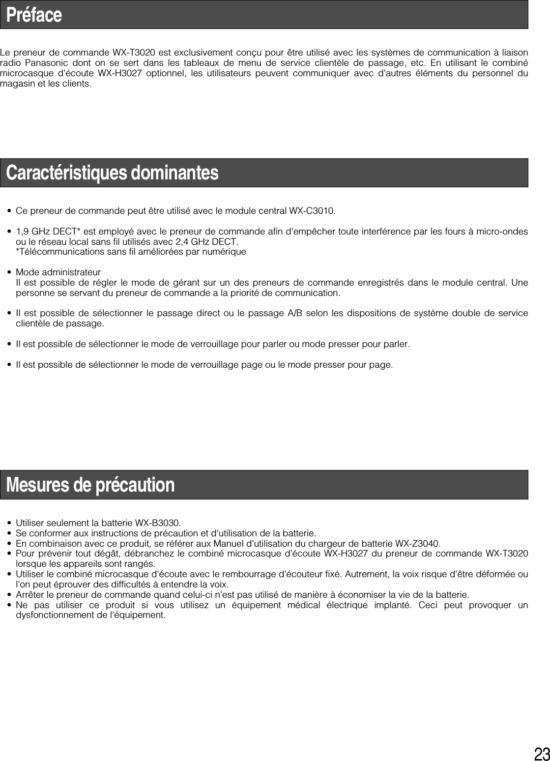
Panasonic of North America 9TAWX-T3020 Wireless Order Taker for DWCS User Manual manual rev
Panasonic Corporation of North America Wireless Order Taker for DWCS manual rev
UserManual.wiki
>
Panasonic of North America
>
9TAWX T3020 User Manual
manual rev
Navigation menu
Upload a User Manual
Namespaces
Wiki Guide
HTML
PDF
Info
Views
User Manual
Discussion / Help
Navigation
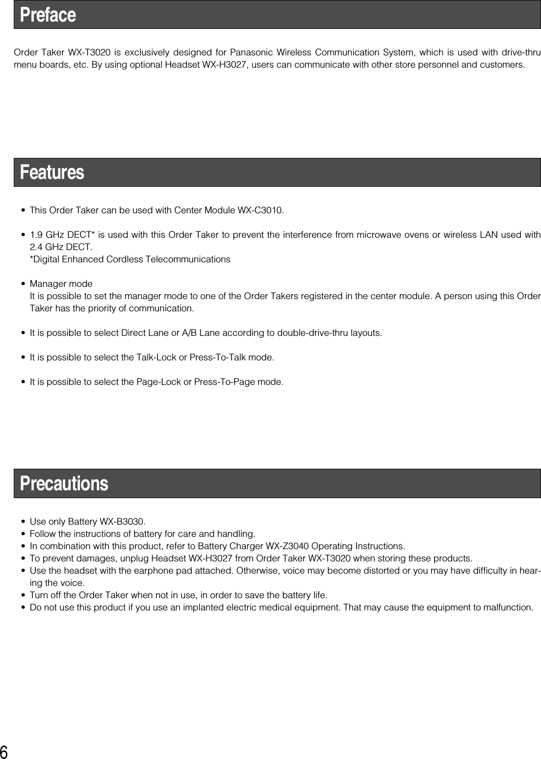
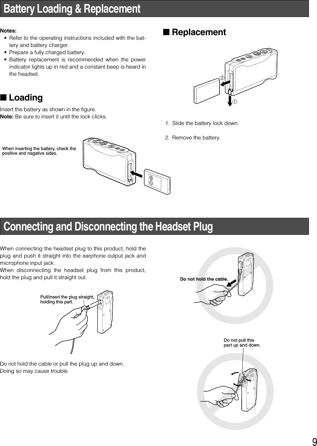
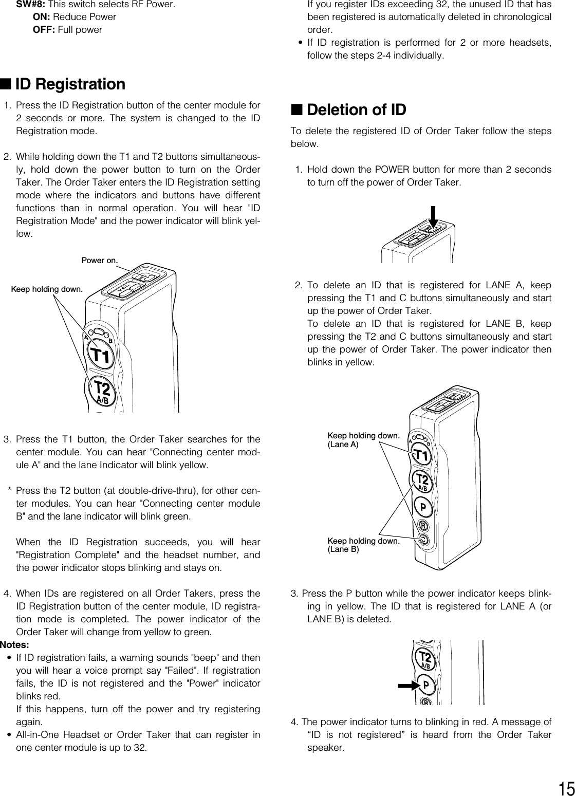
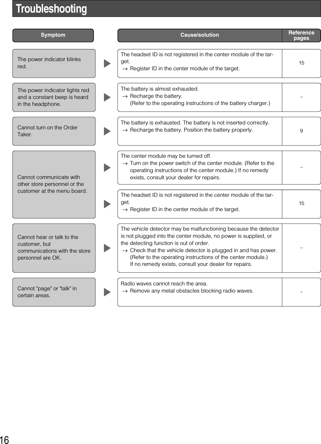
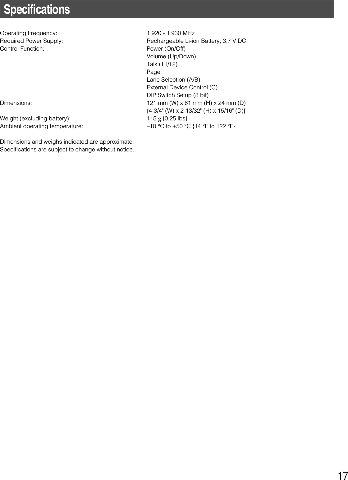
![8qBattery Lock [EJECT]When removing the battery, slide out the lock.When loading a new battery, insert the battery until thelock clicks.Please note the direction that inserts the battery.wTalk 1 Button [T1]This button controls communications with the customeron Lane A.When the button is released, you can hear any customerwho is at the menu-board.While the button is held down in the Press-To-Talkmode, you can speak to the customer.When the button is pressed in the Talk-Lock mode, youcan speak to the customer until you press the button asecond time.eTalk 2 / A/B Lane Selection Button [T2, A/B]This button can be set to two functions by the DIP switchsetting. Refer to P.14 "DIP Switch Setup".[T2]This button controls communications with the customeron Lane B of double-drive-thrus.When the button is released, you can hear any customerwho is at the menu board.While the button is held down in the Press-To-Talkmode, you can speak to the customer who is at themenu board.When the button is pressed in the Talk-Lock mode, youcan speak to the customer until you press the button asecond time.[A/B]This button switches from Lane A to B and vice versa.The lane indicator idisplays the selected lane in yellow(A) or green (B).rPage Button [P]This button controls communications with store person-nel.When the button is released, you can hear the communi-cations among store personnel.While the button is held down in the Press-To-Pagemode, you can speak to store personnel.When the button is pressed in the Page-Lock mode, youcan speak to the store personnel until you press the but-ton a second time.tPhone Button [R]Not used.yExternal Device Control Button [C]Press and hold the C button to turn on the externaldevice.uPower IndicatorThe indicator shows the status as follows.Green: Power is supplied, and the unit is operating.Green blinking: Power is supplied and Manager modeis activated.Red: The battery requires recharging.Red blinking: ID is not registered, or the center moduleis set to the ID Registration mode.iLane IndicatorLights yellow or green to indicate which the lane is inoperation.Yellow: Lane A is selected.Green: Lane B is selected.Yellow blinking: Lane A is being selected, and eitherthe Talk or Page mode is activated.Green blinking: Lane B is being selected, and eitherthe Talk or Page mode is activated.oVolume Control Buttons [ ]Pressing the respective buttons will increase ordecrease the sound level.!0 Power Button [POWER]Pressing the button will turn the Order Taker on.Pressing the button again for 2 seconds or more will turnthe Order Taker off. !1 Earphone Output JackThis jack is used for connection with the Panasonic WX-H3027 Headset.!2 Microphone Input JackThis jack is used for connection with the Panasonic WX-H3027 Headset.!3 Switch CompartmentDo not open the cover of this compartment. It should beopened only by qualified service personnel or systeminstallers.!4 Battery (Optional accessory)Refer to p. 6 "Precautions".+ VOL –](https://usermanual.wiki/Panasonic-of-North-America/9TAWX-T3020/User-Guide-1007629-Page-8.png)
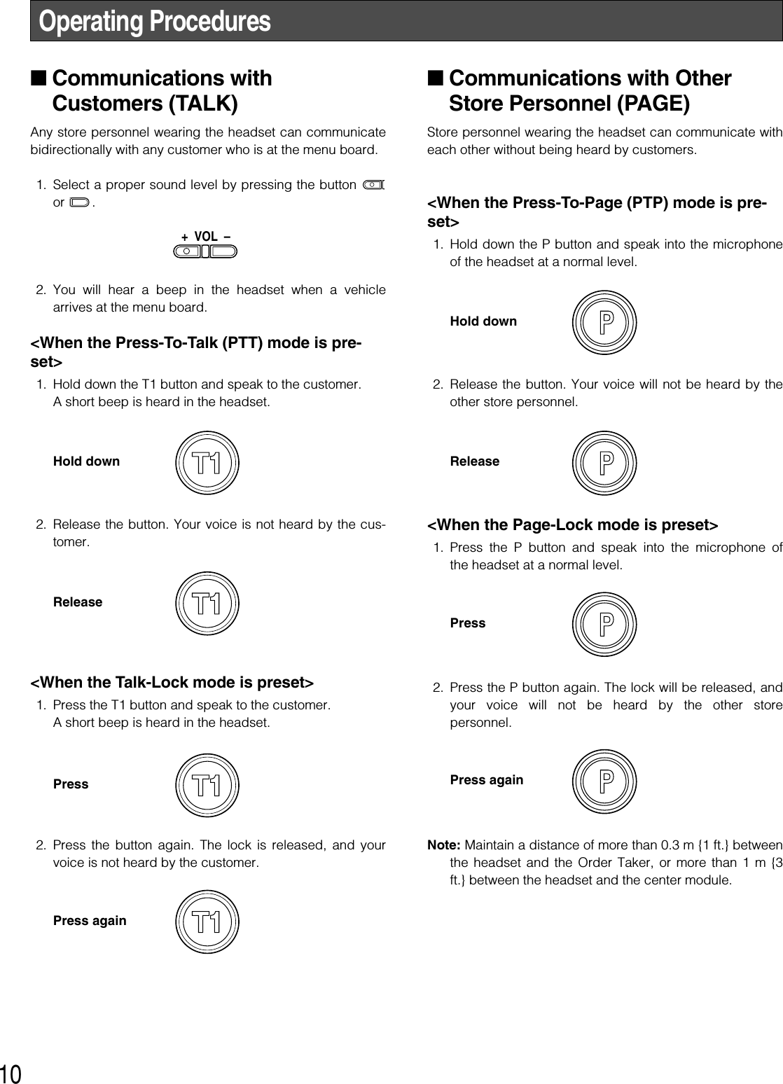
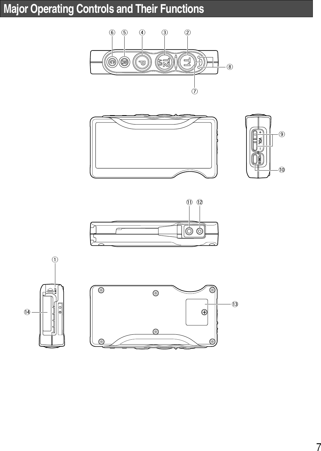
![11■Control of the device control ter-minalsThe device control terminals of the center module can becontrolled through the Order Taker. 1. Hold down the C button. A short beep is heard from thespeaker of the headset and a connection will be madetoward the device control terminals of the center mod-ule. 2. Release the C button. A short beep is heard twice fromthe speaker of the headset and the connection will bedisconnected toward the device control terminals of thecenter module. ■Double-Drive-Thru connectionsWhen Double-Drive-Thru connections are made with thecenter module, any Order Taker is required to select thecenter module of either Lane A or Lane B. <For Normal setup>1. When a connection is made to Lane A, the lane indicatoris lit in yellow. Press the T2 button if you want to make aconnection changeover to Lane B. When connected toLane B, a voice of [Lane B] is heard from the speaker ofthe headset and the lane indicator is lit in green. 2. While a connection is maintained to Lane B, the laneindicator is lit in green. Press the T2 button if you want tomake a connection changeover to Lane A. When con-nected to Lane A, a voice of [Lane A] is heard from thespeaker of the headset and the lane indicator is lit in yel-low. <For Direct Lane Select setup>1. While a connection is maintained to Lane A, the laneindicator is lit in yellow. Press the T2 button if you wantto make a connection changeover to Lane B. When con-nected to Lane B, a voice of [Lane B] is heard from thespeaker of the headset and the lane indicator is lit ingreen. 2. While a connection is maintained to Lane B, the laneindicator is lit in green. Press the T1 button if you want tomake a connection changeover to Lane A. When con-nected to Lane A, a voice of [Lane A] is heard from thespeaker of the headset and the lane indicator is lit in yel-low. Note: When Direct Lane Select is set, TALK is available byselecting either lane pressing T1 or T2 button.Hold downReleasePressPressPressPress](https://usermanual.wiki/Panasonic-of-North-America/9TAWX-T3020/User-Guide-1007629-Page-11.png)
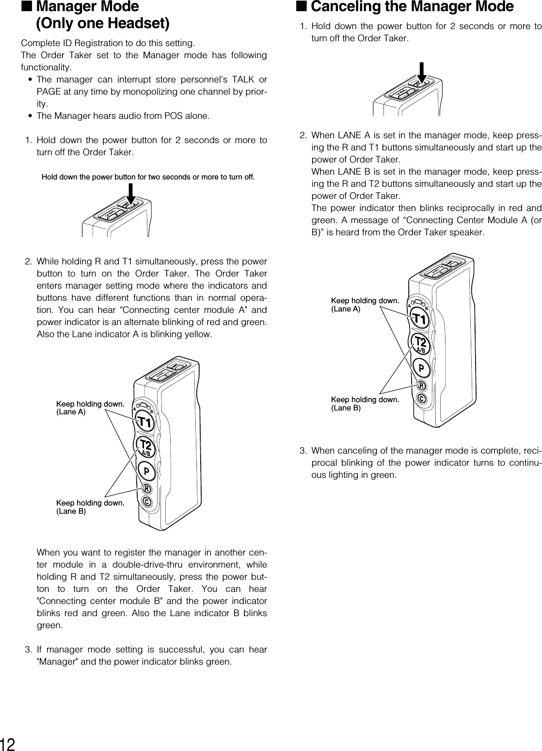
![13■Auto-Talk-Lock setup (for onlyone Headset)For a Order Taker where Auto-Talk-Lock is set up, it has afunction to select [Talk] automatically when the vehicledetector has become active, and you can talk with the cus-tomer at the menu board. 1. Confirm that the dip switch 1 of the headset is ON, thedip switch 2 is set at the objective lane, and the powerof the headset is OFF. 2. Turn on the Order Taker. The message "Hello Headset**" (** is the number of headset) is output from thespeaker of the headset, and the power indicator blinksgreen and red alternately for 3 seconds. While the indi-cator is blinking, press the T1 or T2 button. (LANE A: T1button, LANE B: T2 button) Auto-Talk-Lock will be setup, The message "Auto-Talk-Lock ON" is heard from thespeaker of the headset. When the T1 or T2 button is notpressed, the Order Taker assumes an ordinary opera-tion mode. 3. In the case of a failure in Auto-Talk-Lock setup, a voiceof [Failed] is heard from the speaker of the headset. Inthis case, the same procedures should be followed fromStep 1 again. Note: If the power of the Order Taker is turned OFF, all thesetting conditions for Auto-Talk-Lock will be canceled.This setting should be carried out without fail when thepower supply is started up.](https://usermanual.wiki/Panasonic-of-North-America/9TAWX-T3020/User-Guide-1007629-Page-13.png)
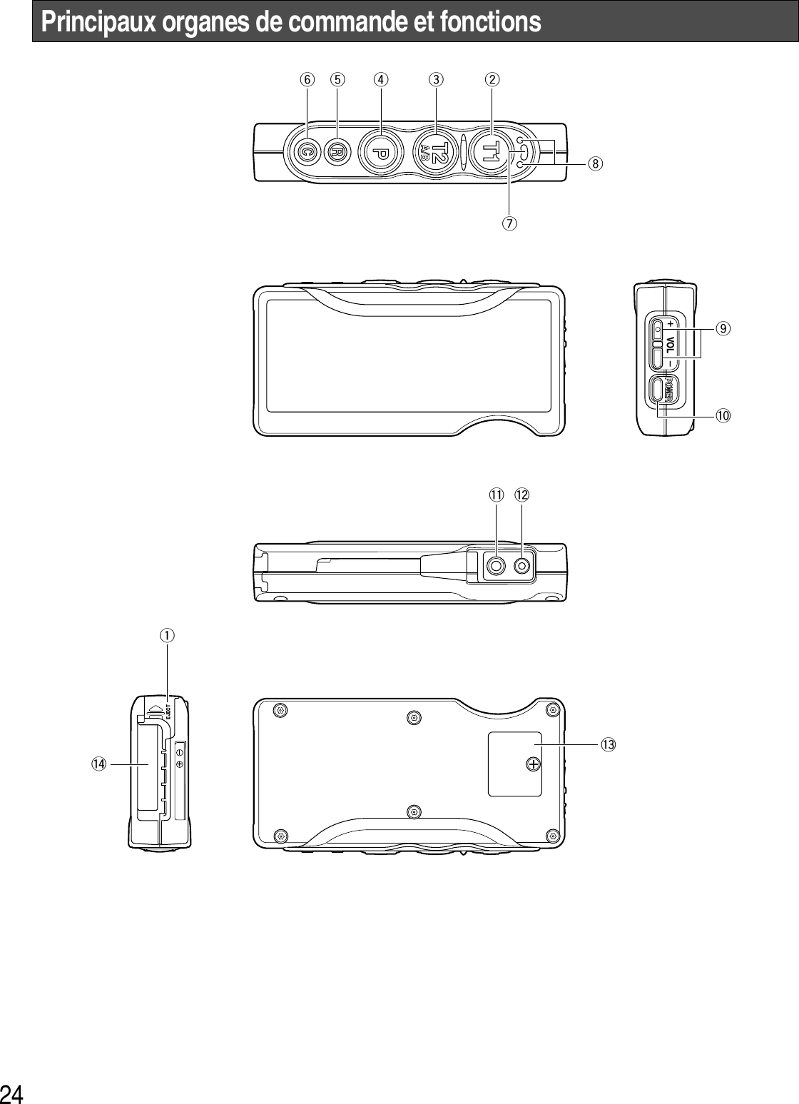
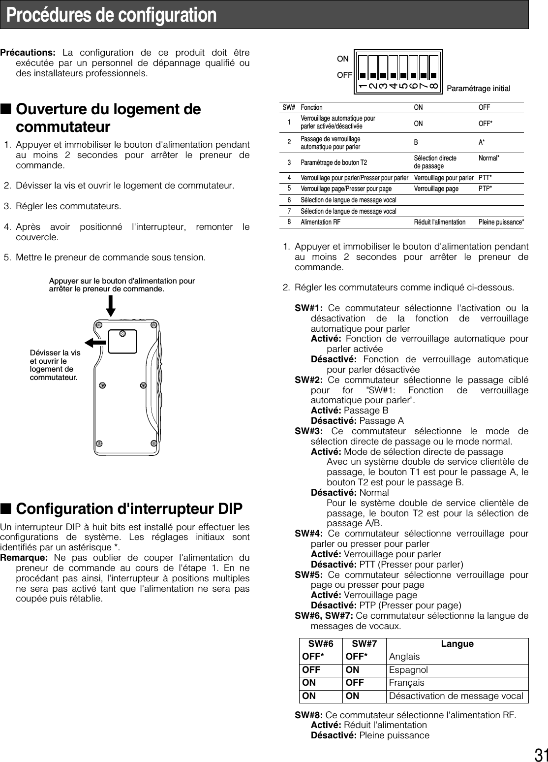
![25qVerrouillage de la batterie [EJECT]Faire coulisser le verrouillage pour retirer la batterie.Lors du chargement d'une batterie neuve, introduire labatterie jusqu'à ce qu'elle se verrouille en place.Veuiller noter le sens pour insérer la batterie.wBouton 1 Parler [T1]Ce bouton contrôle les communications avec le clientsur le passage A.Lorsque le bouton est relâché, tout ce que dit le clientau tableau de menu est entendu.Alors que le bouton est maintenu pressé en modepresser pour parler, il est possible de parler au client.Alors que le bouton est maintenu pressé en mode deverrouillage pour parler, il est possible de parler auclient jusqu'à ce que le bouton soit pressé une secondefois.eBouton de sélection Parler 2 / Passage A/B [T2, A/B]Ce bouton peut être réglé sur deux fonctions suivant leréglage de l'interrupteur à positions multiples. Se référerà p. 31 à "Configuration d'interrupteur DIP".[T2]Ce bouton contrôle les communications avec le clientsur le passage B d'un système double de serviceclientèle de passage.Lorsque le bouton est relâché, tout ce que dit le clientau tableau de menu est entendu.Alors que le bouton est maintenu pressé en modepresser pour parler, il est possible de parler au client setrouvant à la hauteur du tableau de menu.Alors que le bouton est maintenu pressé en mode deverrouillage pour parler, il est possible de parler auclient jusqu'à ce que le bouton soit pressé une secondefois.[A/B]Ce bouton commute entre le passage A et le passage Bet vice versa. L'indicateur de passage iaffiche lepassage actuellement sélectionné en jaune (A) ou envert (B).rBouton Page [P]Ce bouton contrôle les communications avec lepersonnel du magasin.Lorsque le bouton est relâché, les communications entreles membres du personnel du magasin peuvent êtreentendues.Alors que le bouton est maintenu pressé en modepresser pour page, il est possible de parler aupersonnel du magasin.Alors que le bouton est maintenu pressé en mode deverrouillage page, il est possible de parler au personneldu magasin jusqu'à ce que le bouton soit pressé uneseconde fois.tTouche de téléphone [R]N'est pas utilisé.yBouton de commande de périphérique externe [C]Appuyer et maintenir le bouton C enfoncé pour mettreen marche le périphérique externe.uIndicateur d'alimentationL'indicateur montre l'état actuel comme suit.Vert: L'alimentation est appliquée et l'appareil est enfonction.Clignote en vert: L'alimentation est appliquée et lemode de gérant est activé.Rouge: La batterie doit être rechargée.Rouge clignotant: L'identification n'est pas enregistréeou le module central est réglé en mode d'enregistre-ment d'identification.iIndicateur de passageIl s'allume en jaune ou en vert pour indiquer quel est lepassage en service.Jaune: Le passage A est sélectionnéVert: Le passage B est sélectionné.Jaune clignotant: Le passage A est sélectionné et soitle mode parler soit le mode page est activé.Clignote en vert: Le passage B est sélectionné et soitle mode parler soit le mode page est activé.oBoutons de réglage de volume [ ]Une pression des boutons respectifs a pour effetd'augmenter ou de diminuer le niveau de sortie son.!0 Bouton d'alimentation [POWER]Le fait d'appuyer sur le bouton met le preneur decommande en marche. Une nouvelle pression dubouton pendant au moins 2 secondes permet d'arrêterle preneur de commande.!1 Prise de sortie d'écouteurCette prise est utilisée pour le raccordement aucombiné microcasque d'écoute WX-H3027.!2 Prise d'entrée de microphoneCette prise est utilisée pour le raccordement aucombiné microcasque d'écoute WX-H3027.!3 Logement d'interrupteurNe pas ouvrir le couvercle de ce logement. Ne doit êtreouvert que par un technicien professionnel ou desinstallateurs de système qualifiés.!4 Batterie (accessoire optionnel)Se référer à la page 23 à "Mesures de précaution".+ VOL –](https://usermanual.wiki/Panasonic-of-North-America/9TAWX-T3020/User-Guide-1007629-Page-25.png)
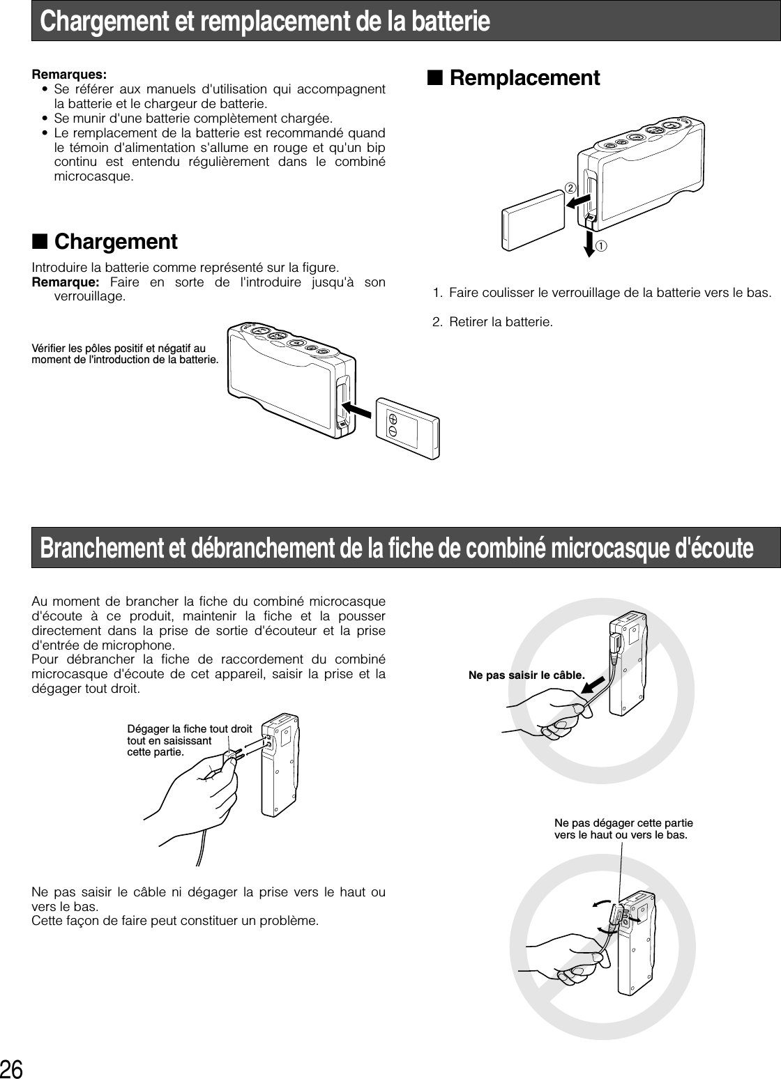
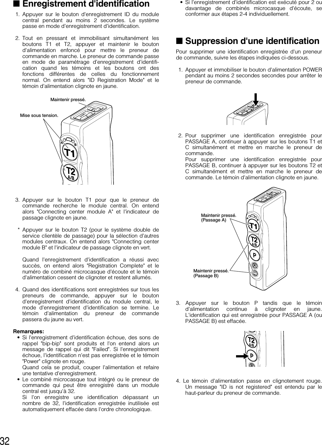
![28■Bornes de commande depériphérique extérieurLes bornes de commande de périphérique du modulecentral peuvent être contrôlées par l'intermédiaire dupreneur de commande. 1. Immobiliser le bouton C en position basse. Un bip courtest entendu par le haut-parleur du combinémicrocasque d'écoute et une connexion sera établie àdestination des bornes de commande de périphériquedu module central. 2. Relâcher le bouton C. Un bip court est entendu deuxfois par le haut-parleur du combiné microcasqued'écoute et la connexion sera coupée vers les bornesde commande de périphérique du module central. ■Connexion de système doublede service clientèle de passage(Double-Drive-Thru)Quand les connexions de système double de serviceclientèle de passage sont établies avec le module central,n'importe quel preneur de commande est obligé desélectionner le module central du passage A ou du passageB.<Pour une configuration normale>1. Quand une connexion est établie au passage A,l'indicateur de passage s'allume en jaune. Appuyer surle bouton T2 si l'on souhaite faire un changement deconnexion vers le passage B. Une fois connecté aupassage B, une voix [Lane B] est entendue par le haut-parleur du combiné microcasque d'écoute et l'indicateurde passage s'allume en vert. 2. Quand une connexion est maintenue sur le passage B,l'indicateur de passage s'allume en vert. Appuyer sur lebouton T2 si l'on souhaite faire un changement deconnexion vers le passage A. Une fois connecté aupassage A, une voix [Lane A] est entendue par le haut-parleur du combiné microcasque d'écoute et l'indicateurde passage s'allume en jaune. <Pour une configuration de système double deservice clientèle de passage>1. Quand une connexion est maintenue sur le passage A,l'indicateur de passage s'allume en jaune. Appuyer surle bouton T2 si l'on souhaite faire un changement deconnexion vers le passage B. Une fois connecté aupassage B, une voix [Lane B] est entendue par le haut-parleur du combiné microcasque d'écoute et l'indicateurde passage s'allume en vert. 2. Quand une connexion est maintenue sur le passage B,l'indicateur de passage s'allume en vert. Appuyer sur lebouton T1 si l'on souhaite faire un changement deconnexion vers le passage A. Une fois connecté aupassage A, une voix [Lane A] est entendue par le haut-parleur du combiné microcasque d'écoute et l'indicateurde passage s'allume en jaune. Remarque: Quand Sélection de passage direct est réglée,TALK est disponible en sélectionnant l'un ou l'autrepassage en appuyant sur le bouton T1 ou le bouton T2.Presser etimmobiliserLibérerPresserPresserPresserPresser](https://usermanual.wiki/Panasonic-of-North-America/9TAWX-T3020/User-Guide-1007629-Page-28.png)
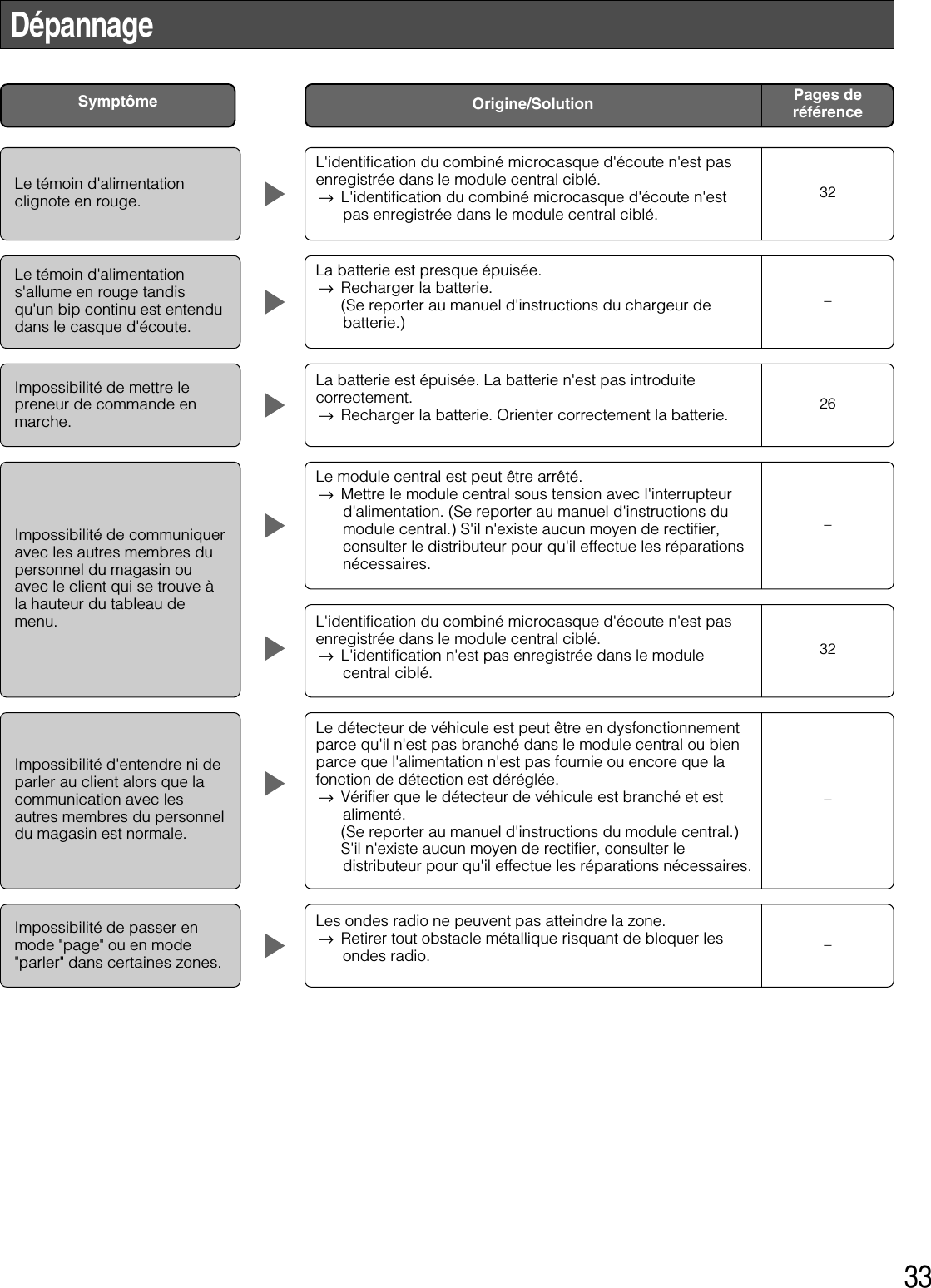
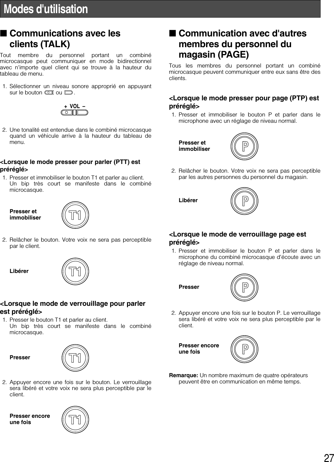
![30■Configuration de la fonction deverrouillage automatique pourparler (pour seulement uncombiné microcasque d'écoute)(Auto-Talk-Lock)Pour un preneur de commande où la fonction deverrouillage automatique pour parler est configurée, il a unefonction pour sélectionner [Parler] automatiquement quandle détecteur de véhicule est devenu actif, et si l'on parleavec le client au tableau de menu. 1. Confirmer que l'interrupteur à positions multiples 1 ducombiné microcasque d'écoute est en fonction, quel'interrupteur à positions multiples 2 est réglé sur lepassage objectif et que l'alimentation du combinémicrocasque d'écoute est coupée. 2. Mettre le preneur de commande sous tension. Lemessage "Hello Headset **" (** correspond au numérodu combiné microcasque d'écoute) est émis par le haut-parleur du combiné microcasque d'écoute et le témoind'alimentation clignote en vert et en rougealternativement pendant 3 secondes. Tandis que letémoin d'alimentation clignote, appuyer sur le bouton T1ou T2. (PASSAGE A: Bouton T1, PASSAGE B: BoutonT2) La fonction de verrouillage automatique pour parlersera paramétrée, le message "Auto-Talk-Lock ON" estentendu par le haut-parleur du combiné microcasqued'écoute. Quand le bouton T1 ou T2 n'est pas pressé, lepreneur de commande assume un mode ordinaire defonctionnement. 3. Dans le cas d'une défaillance de la configuration de lafonction de verrouillage automatique pour parler, unevoix [Failed] est entendue par le haut-parleur ducombiné microcasque d'écoute. Dans ce cas de figure,se conformer à nouveau aux instructions des mêmesprocédures indiquées à l'étape 1. Remarque: Si le courant d'alimentation du preneur decommande est coupé, toutes les conditions de réglagepour la fonction de verrouillage automatique pour parlerseront annulées. Ce réglage devrait être effectué sansfaute quand l'alimentation électrique est appliquée.](https://usermanual.wiki/Panasonic-of-North-America/9TAWX-T3020/User-Guide-1007629-Page-30.png)