Panasonic of North America 9TGWW11A TD-CDMA PCI Express Mini Module User Manual Module Integration guide
Panasonic Corporation of North America TD-CDMA PCI Express Mini Module Module Integration guide
Contents
- 1. User manual - host
- 2. Module Integration guide
- 3. Host User Manual
- 4. Users Manual
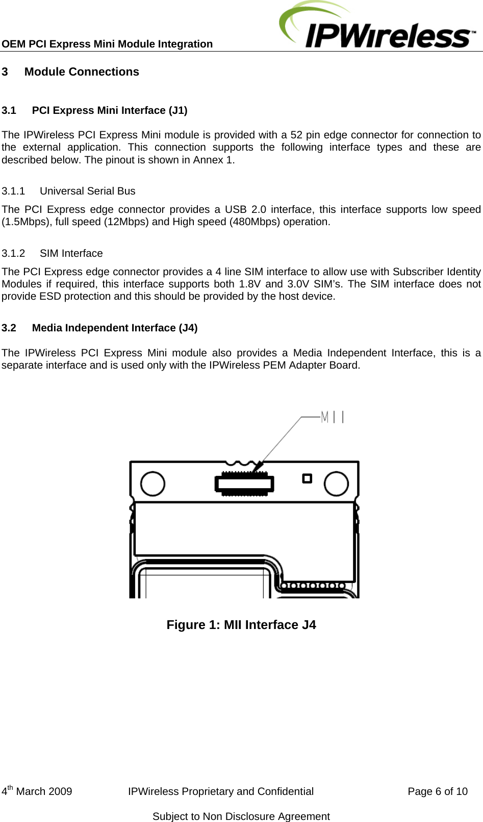
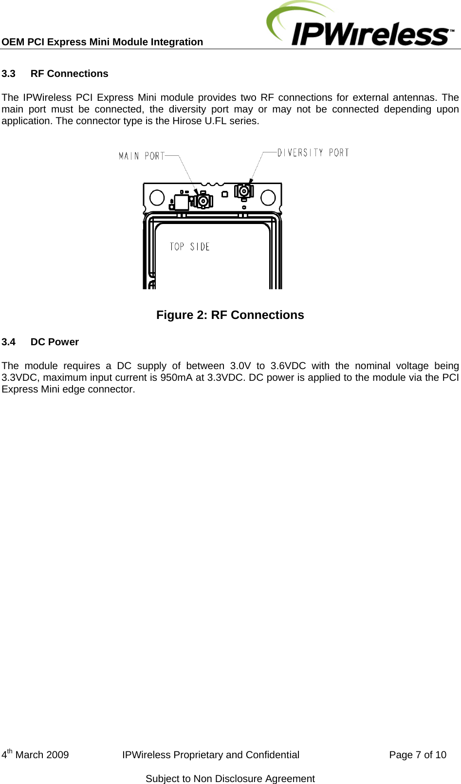
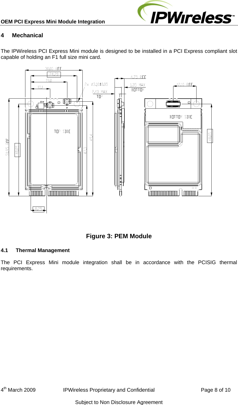
Module Integration guide